1
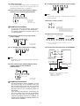
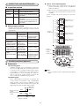
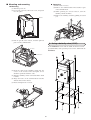
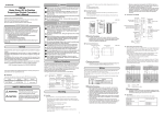
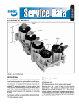
CP-UM-5306E WARNING ECM3000 Control Motor User's Manual • Be sure to turn the power OFF before mounting, removing, or wiring the ECM3000 or opening the cover. Touching electrically charged parts such as power terminals by mistake might cause electric shock. CAUTION • To ensure correct and safe operation of the ECM3000, always follow this user’s manual, as well as user’s manuals for equipment and system to be combined with the ECM3000. • Installation, wiring, inspection, adjustment, and maintenance of the ECM3000 must be carried out only by authorized engineers who have the knowledge and technical skill regarding the customer’s system and the ECM3000. • Use the ECM3000 within the operating ranges recommended in the specifications of this manual. Otherwise device failure or faulty operation may occur. • Do not install the ECM3000 at locations like those listed below. Doing so might cause faulty operation. • Locations with hazardous chemicals, corrosive gas or briny / salty air. • Locations where the ECM3000 is exposed to high temperatures. • Locations with moisture or water droplets. • Locations where the ECM3000 is exposed to vibration for a long period. • Locations where the ECM3000 is exposed to direct sunlight. • Do not use the ECM3000 as a step. Doing so might cause damage to the ECM3000 or personal injury. • Wire the ECM3000 according to electrical wiring standards. Also wire the ECM3000 using specified electric cables according to standard installation methods. Failure to do so might breakdown or faulty operation. • The motor may become hot during operation. Do not touch the motor opening the cover immediately after turning the power OFF. Doing so might cause burn hazard. • Do not touch any moving part when power is ON or during operation. Doing so might cause injury. • To connect with linkage, use the 160˚ stroke motor. Failure to do so might cause faulty operation. The 90˚stroke motor, cannot be used to fully open or close. • If it is predicted that the safety of the system cannot be kept, fail-safe design such as use of double controllers, installation of breaker or installation of limiter, or redundant design should be considered. • When you discard the ECM3000, discard it as an industrial waste following local rules and regulations. Thank you for purchasing the ECM3000 Control Motor. This manual contains information for ensuring correct use of the ECM3000. It also provides necessary information for installation, maintenance, and troubleshooting. This manual should be read by those who design and maintain equipment that uses the ECM3000. Be sure to keep this manual for ready reference. Please read the "Terms and Conditions" from the following URL before ordering or use: http://www.azbil.com/products/bi/order.html NOTICE Be sure that the user receives this manual before the product is used. Copying or duplicating this user’s manual in part or in whole is forbidden. The information and specifications in this manual are subject to change without notice. Considerable effort has been made to ensure that this manual is free from inaccuracies and omissions. If you should find an error or omission, please contact the azbil Group. In no event is Azbil Corporation liable to anyone for any indirect, special or consequential damages as a result of using this product. 2003-2013 Azbil Corporation All Rights Reserved. SAFETY PRECAUTIONS Safety precautions are for ensuring safe and correct use of this product, and for preventing injury to the operator and other people or damage to property. You must observe these safety precautions. Also, be sure to read and understand the contents of this user's manual. WARNING Warnings are indicated when mishandling this product might result in death or serious injury to the user. CAUTION Cautions are indicated when mishandling this product might result in minor injury to the user, or only physical damage to this product. 1 1. OVERVIEW and resistance. Three kinds of power supply voltage types are available, 24Vac, 100Vac, and 200Vac. Additionally, a power supply unit with a voltage range of 85 to 264Vac is also available for the 4 to 20mAdc input type. The ECM3000's bracket is compatible with Azbil Corporation’s previous motors. The ECM3000 is a control motor designed to control various equipment in the industrial application. Two kinds of models are available: one is a 90˚ stroke motor for burner control and the other is a 160˚ stroke motor for valve control of hot and cold water, and steam. Three kinds of control signal input type are available: relay contact, 4 to 20mAdc, 2. MODEL SELECTION GUIDE Model No. ECM3000D0100 ECM3000D0110 ECM3000D1100 ECM3000D1110 ECM3000D2100 ECM3000D2110 ECM3000E0100 ECM3000E0110 ECM3000F0100 ECM3000F0110 ECM3000F1100 ECM3000F1110 ECM3000F2100 ECM3000F2110 ECM3000G0100 ECM3000G0110 ECM3000G0120 ECM3000G9100 ECM3000G9110 ECM3000G9120 ECM3000F0300 *3 ECM3000F0310 *3 ECM3000D0200 ECM3000E0200 ECM3000F0200 ECM3000F1200 ECM3000F2200 ECM3000G0200 ECM3000G0220 ECM3000G9200 ECM3000G9220 ECM3000F0400 *3 Product specifications Power Power supply Input signal Degress Stroke timing Output Control method voltage of rotation 50Hz 60Hz torque consumption 9VA ON-OFF control 24Vac Relay contact 90˚ 39s 33s 12.5N•m 100Vac 200Vac 24Vac Potentiometer Relay contact 100Vac 200Vac 24Vac 4 to 20mAdc *1 11VA 85 to 264Vac 39s 14W 15W 24Vac Relay contact 160˚ 20s 16s 6N•m 14VA 69s 58s 12.5N•m 9VA Potentiometer Relay contact 100Vac 200Vac 24Vac None 4 switches built-in None 4 switches built-in None 4 switches built-in None Position proportional control 4 switches built-in None (feedback potentiometer builtin) 4 switches built-in None 4 switches built-in None 4 switches built-in None 4 switches built-in 2 switches built-in with open/close override function None 4 switches built-in 2 switches built-in with open/close override function None 4 switches built-in None *2 ON-OFF control Position proportional control (feedback potentiometer builtin) 4 to 20mAdc *1 11VA 85 to 264Vac 24Vac Auxilary switch (option) 72s Relay contact 35s 29s 14W 15W 6N•m 14VA 2 switches built-in with open/close override function None *2 2 switches built-in with open/close override function None *2 *1 Switching of direct/reverse control action and adjustment of zero/span and dead band are available. *2 Extension unit can be mounted in the field. *3 High-speed motor type Handling Precautions • The high-speed motor type must be used within a duty ratio (operation ratio) of 40%. • Do not connect an ECM3000F (that is, type F) with a mechanical balancing relay such as R9107A or R927C. Doing so might damage the ECM3000F by applying excessive voltage to its potentiometer. • If an ECM3000F controls the actuator on the basis of the resistance between T and G or between T and Y of the feedback potentiometer, it might not function normally, depending on the connected controller. For details contact the azbil Group. 2 ■ Mounting direction 3. PART NAMES AND FUNCTIONS ● 90˚ stroke motor This type can be mounted in the desired direction. However, do not mount in a way that allows water or foreign matter to enter from the output shaft. Cover: to protect the inside of the ECM3000, resin retaining cover. Cover retaining screws (3) Recommended tighten torque 0.8 to 1.0 N•m Body Control Motor ECM3000E9110 ● 160˚ stroke motor This type can be mounted in the desired direction with the motor output shaft placed horizontally or vertically downward. To prevent condensate water from entering the ECM3000, do not mount with the output shaft pointing upward. Knockout holes Knockouts on left side and right side for cable entry. *123103800150* Pointer (90˚ stroke motor only) Rotating direction label (90˚ stroke motor only) Output shaft: The rotating direction is shown on the label (90˚stroke motor only). When viewed from the output shaft, "R" indicates the opening direction and "L" indicates the closing direction. Mounting hole: Use the M6 screws. Bracket: To mount the body. Handling Precautions • Factory setting of the output shaft: 0% position • L: counterclockwise (CCW) rotation R: clockwise (CW) rotation ● Maintaining splash-proof performance Do not squeeze the packing or cable, and fasten the cover securely. Make the knockout hole watertight. • Use waterproof connectors for cables coming from the ECM3000. Recommended waterproof connector: 83104346-003. • Also when connecting electrical conduits, use a waterproof precut type or the like to maintain waterproofing. Ground terminal (ECM3000E and ECM3000G only) 7 6 4 5 3 2 1 Terminal block: M3.5 screws 5. WIRING D C B For wiring, open a knockout hole (22mm dia.) in the side panel. Wiring must be done according to the terminal label indicated on the respective terminals. Connect each core using M3.5 insulated crimp type terminal lugs. A 0 100 Auxiliary switches (4 or 2 switches): Availability depends on the model No. Amperage adjuster on 4–20mA input models: Switching of direct/reverse control action and adjustment of zero/span and dead band are available. Handling Precautions • To remove the knockout, tap lightly around its edge using a flat-head screwdriver. • Make sure that fragments do not enter the control motor when a knockout hole is opened. • Do not use unused terminals as relay terminals. • Always be sure to attach the cover after wiring. • Do not lay the power and signal cables together in the same conduit. • Keep the power line cables 50cm or more away from the signal cables. • If routing, the power and signal cables together in the same conduit is unavoidable, it is recommended to use shielded signal cables as specified below. • Connect the power supply voltage according with the model No. • Be sure to install a circuit breaker for the electrical power. • Set the parameters of the controller, so that the internal relay of the controller does not turn ON and OFF excessively due to hunting during motor operation. For example, set derivative time (D) to 0 seconds or widen the dead band. If the internal relay operates excessively, the life of the motor or the relay of the controller on the host side might be shortened. If the frequent operation cannot be avoided, an auxiliary relay should be installed between the motor and the controller. Terminal assignments Models with 4 built-in auxiliary switches 7 6 5 4 3 2 1 D3 D2 D1 C3 C2 C1 B3 B2 B1 A3 A2 A1 Power and each input Auxiliary switches A-D Models with 2 built-in auxiliary switches and open/close override function 7 6 S B3 5 4 CONT CW B2 3 2 1 CCW unused unused B1 A3 A2 A1 Power and each input Open/close override function Auxiliary switches A and B 4. MOUNTING ■ Mounting locations Do not install the ECM3000 at locations specified in the cautions. Additionally, when installing the ECM3000 outdoors, an appropriate protective device, such as a protective cover, must be installed. Handling Precautions • Pay special attention that no foreign matter or moisture enters from the output shaft. • In an application where the ECM3000 is combined with a control valve, such as fluid control, condensed moisture content is transferred along the valve and might enter the interior of the motor when the control valve is located higher than ECM3000. 3 ● 4 to 20mA input (85 to 264Vac power supply) ● Cables to be used Use JIS C3307 600V insulated wire or equivalent for the power line cables. For the signal cables, use JCS4364 instrument cable or equivalent. to 2 3 R − M 1 + ● Relay contact input (24Vac power supply) (nominal 135Ω feedback potentiometer) L Note • Terminals 2 and 5 are isolated from each other inside the motor. 4 5 6 G Y T Unused 7 ● Auxiliary switch (4 units) L: (CCW) rotation R: (CW) rotation CW:Clockwise, CCW:Counterclockwise L COM R Handling Precautions • In case of ON-OFF control action type, terminal Nos. 4, 5 and 6 are not connected. • The factory setting for the output shaft is the 0% open position. A1 2 3 4 5 24Vac 6 B W L (a) Force open CCW CW CONT S L: (CCW) rotation R: (CW) rotation 3 4 5 + 24Vac (c) Automatic operation (factory setting) 6 − CCW CW CONT S CCW CW CONT S Note: At any one time, terminal S may be connected to only one of CCW, CW or CONT. R ● 4 to 20mAdc input (24Vac power supply) 2 (b) Force closed 7 R Unused F.G. 1 L: (CCW) rotation R: (CW) rotation Note: The internal switch connections for B, C, and D have the same layout as for A. Models with open/close override function have only A and B switches. A3 ● Open/close override input ● Resistance (nominal 135Ω) input (24Vac power supply) 1 A2 ● Full open/full close operation for ECM3000E 7 W XO Unused 4 to 20mAdc B XC 4 W 5 B F.G. R Note • Terminals 2 and 5 are isolated from each other inside the motor. Azbil Corporation L91 pressure regulator full open switch full close switch ● Relay contact input (100Vac/200Vac power supply) (nominal 135Ω feedback potentiometer) 2 T2 ECM3000E resistance) Power M L 1 T1 (nominal 135 XO 1 6 R XC Transformer 100% at XO open 0% at XC open 2 R 3 4 5 6 G Y T Unused Note: Recommended contact rating for XO and XC Material; Gold plated Rated voltage; 15Vdc or more Rated current; 100mA 7 100Vac or 200Vac L: (CCW) rotation R: (CW) rotation Handling Precautions • Set the parameters of the controller, so that the internal relay of the controller does not turn ON and OFF excessively due to hunting during motor operation. For example set derivative time (D) to 0 seconds or widen the dead band. If the internal relay operates excessively, the life of the motor or the relay of the controller on the host side might be shortened. If the frequent operation cannot be avoided, an auxiliary relay should be installed between the motor and the controller. 4 ● How to set the operating point 6. INSPECTION AND MAINTENANCE (1) After moving the output shaft to the desired position electrically, set the arrow to the mark with a screwdriver. Item Appearance check Running condition ▲ ■ Inspection method Cycle Once every 6 months Once every 6 months Method • Check for loose screws • Check motor for damage • Check for smooth motor operation • Check for any abnormal noise or vibrations Daily inspection As required • Check for any abnormal noise or vibrations • Check for smooth motor operation • Check that no hunting occurs in the motor (2) Move the motor around electrically to the various set positions and check that the switches work normally. In the example below the setting is at the 50% position. COM NC A1 Auxiliary switches Sw.A (variable 5 to 95%) A2 NO A3 ■ Maintenance method COM NC B1 Visually check the motor operation once every six months. If any problem is found, take corrective actions appropriately. Auxiliary switches Sw.B (variable 5 to 95%) B2 NO B3 Terminal assignments Symptoms • Does not rotate Check item Corrective action • Wiring status, • Check the wiring disconnections • Power supply voltage • Check the power supply voltage • Stopped during operation • Loose terminals • Re-tighten the terminals • Auxiliary switch does • Auxiliary cam switch • Redo the settings not operate status (model with optional • Wiring status, • Check the wiring auxiliary switch) disconnections • Feedback potentiometer • potentiometer resistance • Redo the settings does not operate • Wiring status, • Check the wiring (model with optional disconnections feedback potentiometer) • Loose terminals • Re-tighten the terminals • Control sensitivity • Wiring status, • Check the wiring drops disconnections • Motor torque drops • Loose terminals • Re-tighten the terminals • Power supply voltage • Check the power supply voltage COM NC C1 Auxiliary switches Sw.C (variable 5 to 95%) C2 NO C3 COM NC D1 D2 Auxiliary switches Sw.D (variable 5 to 95%) NO D3 Terminal assignments A Terminal assignments B 7. Auxiliary switches (optional) ■ Adjustment ● Operating point Auxiliary switches A, B, C and D turn on when the arrow is at the mark. The operating point can be set in the 5–95% of output opening range and its repeatability is within ±3%. The differential is approximately 2%. After changing the setting, be sure to test that the switch operates between the motor’s fully open and fully closed positions. Setting auxiliary switch arrows ▲ Note • Use a screwdriver with a 6mm wide blade (JIS B 4609). ● Working type If the output position exceeds the set position, the contact between terminals 1 and 2 (COM-NO) makes and the contact between terminals 1 and 3 (COM-NC) breaks. The example below shows this happening at the 50% position while opening. Differential: approx. 2% Between terminals 1 and 2 Between terminals 1 and 3 10% OFF ON ON OFF 50% 90% Degree of opening 5 ■ Mounting and removing ● Removing (1) Remove the 2 screws. (2) Remove the terminal block. The bracket is part of the terminal block. (3) While pushing the release button, turn the auxiliary switch clockwise. (4) Remove the auxiliary switch by pulling it toward you. ● Mounting (1) Turn the power off. (2) Loosen the 3 screws, remove the cover, and put it in a safe place. Screws (1) (2) (4) (1) (3) (3) Button (3) Lift off part B of the chassis, and then pull out part A of the terminal block. 8. Using a butterfly valve (V51E) If the ECM3000 is used with the V51E, mount the base kit (83165292-001, sold separately) between the V51E and the ECM3000. B of chassis A of the terminal block (4) Insert the shaft of the auxiliary switch into the center of the actuator. The triangular arrow should be pointed toward the scale. (5) Turn the auxiliary switch counterclockwise until it clicks. (6) Align the holes on the terminal block bracket with the holes in the chassis. (7) Insert and tighten the 2 screws. ECM3000 (7) (7) (5) Base kit (4) (6) (6) V51E 6 ■ Optional parts 9. SPECIFICATIONS Name Crank arm Damper arm Ball joint Valve linkage Damper linkage Base kit for V51E Waterproof connector Power transformer for 24Vac Extension Auxiliary switches (4 units built-in) unit* Auxiliary potentiometer for 90˚ type Auxiliary potentiometer for 160˚ type ■ Specifications Item Operation mode Specifications ON-OFF or position proportioning (determined by model No.) Control signal input Relay contact, 4 to 20mAdc, Nominal 135Ω resistance (determined by to model No.) Nominal value of feedback 135Ω, 0.5W potentiometer Max. applied voltage 5Vdc of potentiometer Input impedance 45Ω ± 5% (for 4-20mAdc input signal) Degress of rotation 90˚ or 160˚(determined by model No.) Motor 90˚ stroke •39/33s (relay contact, no-load, 50/60Hz) timing model •39s (power supply voltage 85Vac to 264Vac, no-load, 50/60Hz) •20/16s (relay contact, no-load, 50/60Hz,high-speed motor type) •69/58s (relay contact, no-load, 50/60Hz) 160˚ stroke model •72s (power supply voltage 85Vac to 264Vac, no-load, 50/60Hz) •35/29s (relay contact, no-load, 50/60Hz,High-speed motor type) Output torque 12.5N•m (high-speed motor type: 6N•m) Power supply voltage 24Vac±15% (50/60Hz) 100Vac±10% (50/60Hz) 200Vac±10% (50/60Hz) 85 to 264Vac (50/60Hz) Power consumption See MODEL SELECTION GUIDE (during operation) page 2 Standard operating conditions 23± 2˚C, 50± 10% RH Ambient temperature -20 to +60˚C Ambient humidity 5 to 95% RH (non-condensing) Vibration resistance 4.9m/s2 Insulation resistance Between power supply terminals and casing, between input terminals and casing: 5MΩ or more by 500Vdc megger Between auxiliary switch terminals and casing: 20MΩ or more by 500Vdc megger Dielectric strength Between power supply terminals and casing, between input terminals and casing: 500Vac for 60s (24Vac type), 1200Vac for 60s (100Vac type), 1500Vac for 60s (200Vac type, 85 to 264Vac type). Between auxiliary switch terminals and casing: 1500Vac for 60s. Between power supply terminals and casing, between open/close override input terminals and casing: 500Vac for 60s (24Vac type), 1500Vac for 60s (85 to 264Vac type). Open/close override No-voltage contact input Rating: 15Vdc or more, 100mA or more Resistance: 10MΩ or less (1mAdc) Protection Splash-proof structure IP54 or equivalent (waterproof cable gland must be used.) Materials Case: Die-cast aluminium Cover: Polycarbonate resin with GF Bracket: Steel Mass Approx. 3kg Part No. N-3128 J-26026G-ARM J-27518-JOINT Q455C, D Q605A, D, E 83165292-001 83104346-003 AT72-J1 83165271-004 83165272-001 83165272-002 * Only one type of extension unit can be mounted on the model without internal auxiliary switch. Handling Precautions • The output of the auxiliary potentiometer cannot be connected to an M904E Modutrol motor and to an ECM3000E Modutrol motor. Use the potentiometer for output to an external degree of opening indicator or the like. ● Auxiliary switch Item Auxiliary switches Contact rating Auxiliary switch position factory setting *1 Setting range Terminal (4 units or 2 units) *2 Specifications 4 units (2 units) 250Vac, 5A (resistive load) A, C: Position of 9˚± 5˚ B, D: Position of 81˚± 5˚ Variable 5 to 95% 1 Common 2 NO (Normally Open) 3 NC (Normally Close) *1 For the 90° stroke model with auxiliary switches at factory settings. *2 Models with open/close override function have only A and B switches. ● Auxiliary potentiometer Resistance Accuracy Hysteresis Voltage variation of terminal Y Max. applied voltage 1kΩ ±10% ±8%FS ±5%FS 14% ±6% (0% open) to 86% ±6% (100% open) 5Vdc ■ Applicable standards EN55011 classA, EN61000-6-2, UL873 class2 24Vdc model only, except for the following model nos. • ECM3000F0300 • ECM3000F0310 • ECM3000F0400 7 ■ External dimensions Unit: mm Degress of rotation A B C 90˚ type 32.5 161.6 22 160˚ type 20.5 149.6 12 ! "#$ 45˚ 2. 4± Keyway 1 4. Output shaft 5± 0. 90˚ 1 160˚ 9. 10˚ Closed position Closed position 0. 5 sq ua re 0% position of the output shaft (view from the output shaft) 1. 2± 0. 0 11.8-0.1 dia. 90˚ stroke motor 1 Open position Open position 160˚ stroke motor Handling Precautions • The length of the output shaft may vary depending on the model No. • Only the 90˚ stroke motor has a pointer. Specifications are subject to change without notice. (09) 1-12-2 Kawana, Fujisawa Kanagawa 251-8522 Japan URL: http://www.azbil.com 8 1st edition: Dec. 2003 (E) 7th edition: Feb. 2013 (F)