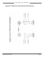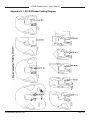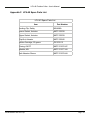
1
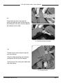
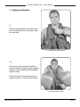
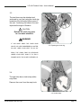
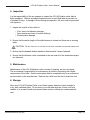
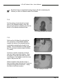
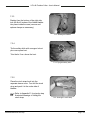
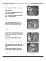
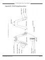
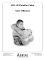
LPU- 40 Flotation Collar
User’s Manual
Aerial Machine and Tool Corp.
4298 JEB Stuart Hwy
Meadows of Dan, VA 24120
www.aerialmachineandtool.com
Phone: 276-952-2006
FAX: 276-952-2231
List of Revisions or Amendments
Date
Revision or Amendment
12 January 2010
Addition of annual and funtional inspection procedures
29 March 2011
Correction of CO2 bottle size
26 March 2012
Correction to Green Plastic Safety Clip PN
26 March 2012
Address/Logo change
LPU-40 Flotation Collar - User’s Manual
Table of Contents
1.
Introduction
4
2.
Attaching the Collar to the Vest
5
3.
Inflating the Bladder
8
4.
Inspection
12
5.
Maintenance
12
6.
Storage
12
7.
LPU-40 Flotation Collar Repack Instructions
13
8.
Annual Inspection
20
9.
Functional Inspection
21
Appendix A. LPU-40 Flotation Bladder Nomenclature
22
Appendix B. LPU-40 Casing Nomenclature
23
Appendix C. Bladder Evacuation Attachment Nomenclature
24
Appendix D. LPU-40 Bladder Folding Diagram
25
Appendix E. LPU-40 Folding Cinch Strap Diagram
26
Appendix F. LPU-40 Spare Parts List
27
Copyright Notice
This owner’s manual is copyrighted, all rights reserved. It may not, in whole or in
part, be copied, photocopied, reproduced, translated or reduced to any electronic
medium or machine readable form without prior consent in writing from Aerial
Machine and Tool Corp.
Copyright
Aerial Machine and Tool Corp.
©
2007 Aerial Machine & Tool Corp.
Page • 3
LPU-40 Flotation Collar - User’s Manual
The following symbols are used throughout this manual:
Warnings indicate a procedure or situation that may result in serious
injury or death if instructions are not followed correctly.
Cautions indicate any situation or technique that will result in potential
damage to the product, or render the product unsafe if instructions are not
followed correctly.
Notes are used to emphasize important points, tips, and reminders.
1. Introduction
The LPU-40 Flotation Collar is a flotation device designed to support air crewmen
stranded in water. The collar is attached to the air crewman’s flight vest. It provides a
minimum of 65 pounds of flotation buoyancy and is designed to keep the user’s head
above the water for an extended period of time.
The LPU-40 is packed in a low profile casing made of fire resistant Nomex® that is
designed to open when the dual-chambered bladder inflates. A single-pull beaded
handle, when manually pulled, activates two 29-gram CO2 gas cartridges for inflation.
Two oral inflation tubes allow the user to manually increase, decrease, or maintain the
air pressure in the bladder chambers.
The capacity of the CO2 cartridges can range from 28 to 31 grams.
Your LPU-40 Flotation Collar is an important piece of survival equipment. Proper care
and maintenance will ensure your vest will accomplish the level of safety performance it
is designed for. It is important that you become familiar with these instructions to safely
use this flotation collar.
WARNING
keep your flotation collar in usable condition.
Improper wear
may result in damage to the collar. do not wear any garment or
piece of equipment over the collar. improper use or negligent
care of this equipment can cause serious injury or death.
Aerial Machine and Tool Corp.
Page • 4
LPU-40 Flotation Collar - User’s Manual
2. Attaching the Collar to the Vest
Top
2.1
The collar attaches to the vest with
a MOLLE Strap system and has four
attachment straps: two on the top of the
collar, and two on the bottom.
Bottom
2.1 Attachment points.
Back
2.2
The attachment points for the top of the
collar are on the back of the vest.
The attachment points for the bottom of the
collar are on the front of the vest at chest
level.
Front
2.2 Attachment points.
Aerial Machine and Tool Corp.
Page • 5
LPU-40 Flotation Collar - User’s Manual
2.3
Attach the top of the collar to the vest first.
Thread the MOLLE straps on the collar
through the channeled webbing on the
vest and secure the Pull-the-Dot fasteners.
Each strap has two Pull-the-Dot fasteners.
Ensure that all four Pull-the-Dot fasteners
are fastened.
2.3 Attaching the top.
2.4
The bottom attachment is threaded
through four webbing straps on each side
of the vest.
On each side of the vest, weave the
MOLLE strap through the first two
channels on the vest and collar.
2.4 Attaching the bottom.
Aerial Machine and Tool Corp.
Page • 6
LPU-40 Flotation Collar - User’s Manual
2.5
Thread both the collar strap and the
closing tab with the snap stud through the
third channel on the vest, then through the
last channel on the collar.
2.5 Threading the bottom channels.
2.6
Thread only the collar strap through the
last vest channel.
Wrap the strap around the vest channel
and secure the Pull-the-Dot fastener.
Tuck the end of the closing tab underneath
the collar casing.
2.6 Closing the snap.
Aerial Machine and Tool Corp.
Page • 7
LPU-40 Flotation Collar - User’s Manual
3. Inflating the Bladder
3.1
Grab the beaded handle with either hand
and forcefully pull down to release it from
the cover flap.
3.1 Grabbing the beaded handle.
3.2
Continue to pull the handle forcefully in
the down-and-out direction; apply constant
pressure on the handle until the bladders
begin to inflate.
Repeat this step if the bladder does not
begin to inflate or if only one lobe inflates.
3.2 Activating the CO2 gas.
Aerial Machine and Tool Corp.
Page • 8
LPU-40 Flotation Collar - User’s Manual
3.3
The two lobes may be attached and
anchored to your vest using the cinch ring
located on the left-inside-bottom area of
the vest. Anchoring the lobes to the vest
improves the angle of flotation.
CAUTION
Release the cinch ring prior
to over-water missions.
WARNING
if you must drop the cinch ring
while you are submerged in water,
3.3 Exposing the cinch ring.
do not unzip your vest to do so.
drop the cinch ring by reaching
under your vest while it is fully
donned with the slide fastener up.
3.4
The right lobe has a cinch strap with a
snap hook.
Remove the cover from the snap hook.
3.4 Anchor strap.
Aerial Machine and Tool Corp.
Page • 9
LPU-40 Flotation Collar - User’s Manual
3.5
Route the cinch strap through the loop on
the left lobe and attach the snap hook to
the cinch ring.
3.5 Routing the strap.
3.6
Tighten the cinch strap by pulling on
the free end until the flotation lobes are
brought close together.
3.6 Adjusting the cinch strap.
Aerial Machine and Tool Corp.
Page • 10
LPU-40 Flotation Collar - User’s Manual
3.7
The oral inflation tubes are on the right
lobe. The valve has a rubber mouth piece
and a knurled locking nut.
Temperature changes may effect the
pressure in the bladder. Use oral inflation
to increase or relieve pressure from the
bladder.
Turn the knurled locking nut clockwise until
it stops.
Push the valve in with your mouth and
blow air into the bladder to increase the
pressure.
Depress the valve to release pressure
from the bladder.
3.7 Oral inflation.
Tighten the knurled locking nut by turning
it counter clockwise when you are finished.
3.8
For improved angle of flotation, put your
arms through the straps that run down the
sides of the bladder until the lobes are tight
against your body.
3.8 Arm placement.
Remember:
Panic and fatigue cause drowning.
Stay calm and conserve your energy.
Aerial Machine and Tool Corp.
Page • 11
LPU-40 Flotation Collar - User’s Manual
4. Inspection
It is the responsibility of the air crewman to inspect the LPU-40 flotation collar before
flight operations. Perform a preflight inspection prior to each flight and at intervals not
to exceed 30 days. If damage is found during an inspection, the vest must be grounded
until repaired.
1. Inspect the outside of the collar for:
• Cuts, tears, and abrasion damage
• Open seams and loose or broken stitching
• Contamination damage
2. Ensure that the entire length of the slide fastener is closed and there are no missing teeth.
CAUTION: Do not open the flotation collar slide fastener for routine inspection.
3. Ensure that the beaded inflation handle is attached with 3 snaps fastened.
4. Ensure that the flotation collar is attached to the vest and all of the attachment snaps are fastened.
5. Maintenance
Maintenance of the LPU-40 flotation collar consists of cleaning, service, and repair.
The air crewman’s responsibility for maintenance is limited to inspecting the outside
components of the collar. Service and repairs shall be completed only by an authorized
service station or the manufacturer. Remove the collar from the vest to wash the vest.
6. Storage
Store your LPU-40 Flotation Collar on a clothes hanger away from direct sunlight in
a dry, well ventilated place. Do not store your collar near sources of heat such as a
radiator, or in a warm humid environment where mold or mildew can contaminate the
vest.
Aerial Machine and Tool Corp.
Page • 12
LPU-40 Flotation Collar - User’s Manual
7. LPU-40 Flotation Collar Repack Instructions
7.1 Preparation
Repack the LPU-40 on a large flat surface big enough to accommodate the bladders
when they are spread flat with no air in them. Orientation references the wearer’s right
and left.
The required tools are:
•
•
•
•
Replacement CO2 bottle, Mil-C-25369, 29 gram, 2 each.
Slide Fastener (zipper) for closing the Nomex® case.
Green safety clips, 2 each.
Optional: clamps with soft rubber or plastic inserts to hold the bladder while packing.
7.1.1
Deflate the bladder by unlocking both oral tube valves. Depress the valves to
release the pressure. While keeping the valves pressed in, gently compress the
bladder with your hands and arms. This will force the air through the oral tubes.
7.1.2
Remove the flotation collar assembly from the vest and harness.
7.1.3
Lay the flotation collar flat on the table with the underside down. Ensure that
the closing zipper is fully disengaged. Spread the Nomex® case open and
completely lay out the bladder.
7.1.4
Remove and discard spent or punctured CO2 cylinders.
7.1.5
Visually inspect the Nomex® case, inflatable bladder, and components of the
flotation collar. Replace damaged bladder and/or components as necessary.
7.1.6
Place the actuator levers in the up-andarmed position. Install two new CO2
cylinders (Mil-C-25369, 29 gram).
Hand tighten the cylinders (avoid over
tightening). Install a green safety clip on both
of the actuators.
7.1.6 Installing the green safety clips.
Aerial Machine and Tool Corp.
Page • 13
LPU-40 Flotation Collar - User’s Manual
7.1.7
It is important that all the trapped air be
removed to aid in the repack of the bladder
assembly and to provide for a compact and
low profile collar.
Remove trapped air by unlocking both oral
tube valves and depressing them. A small
electric vacuum pump used with the bladder
evacuation hose adapter with dual holes
(P/N: AMTC-M2026) may be used to aid in
removal of the trapped air.
7.1.7 Removing the air from the bladders
7.1.8 Release and lock the oral inflation tubes in the closed and locked position.
7.2 Folding the Bladder
Refer to Appendix D. for step-by-step illustrated drawings of Section 7.2: Folding
the Bladder.
7.2.1
Lay the bladder out flat on the table.
Position the actuators and the oral tubes
facing up.
7.2.1 Preparing the bladder for folding.
Aerial Machine and Tool Corp.
Page • 14
LPU-40 Flotation Collar - User’s Manual
Small shot bags or small plastic spring clamps will aid in maintaining the
folds as you work on different areas of the bladder.
7.2.2
Fold the bottom of both the left and right
lobes of the inflatable bladder under and
along a horizontal line extending out from the
bottom of the bladder attachment tabs.
7.2.2 Folding the bottom of the lobes.
7.2.3
Fold over the left lobes (the side with the
CO2 actuators) of the inflatable bladder
towards the center of the assembly along
a vertical line extending the length of the
bladder. This fold should be up tight against
the CO2 actuators/cylinders (approximately
3” in width).
Continue to fold the remainder of the left
lobe onto itself in accordion fashion. Align
the edges of the folds with either the inner
vertical edge of the bladder or with the outer
edge of the previous fold.
When completed, there will be a total of
three accordion-type folds that are 3” wide as
measured along the left extension. Clamp
the folds to hold them in place.
7.2.3 Folding the left side.
Aerial Machine and Tool Corp.
Page • 15
LPU-40 Flotation Collar - User’s Manual
7.2.4
Take the right lobes (the side with the oral
inflation tubes) and make a fold toward the
center of the assembly along a vertical line
extending the length of the inflatable bladder.
This fold should be approximately 3” in width
from the inner edge of the bladder.
Continue to fold the remainder of the right
lobe onto itself in accordion fashion. Align
the edges of the folds with either the inner
vertical edge of the bladder or with the outer
edge of the previous fold.
When completed, there will be a total of
three accordion-type folds that are 3” wide as
measured along the left extension. Clamp
the folds to hold them in place.
7.2.4 Folding the right side.
7.2.5
Fold the top of the bladder next. From the
top of the right extension, fold the bladder
over and along a 45˚ angle from the
horizontal.
Repeat the previous step for the opposite
side (top left lobe).
7.2.5 Folding the top.
Aerial Machine and Tool Corp.
Page • 16
LPU-40 Flotation Collar - User’s Manual
7.2.6
Fold the top of the bladder under and along
a horizontal line approximately 3” from the
top of the neckline. Clamp the top folds to
prevent undoing.
7.2.6 Folding the top.
7.3 Packing the Bladder in the Nomex® Case
7.3.1
Wrap the Nomex® case around the bladder.
Fold the bladder concealment tab over the
bladder.
7.3.1 Packing the bladder.
7.3.2
Thread size “B” nylon safety thread through
the safety stitch eyelets.
Install the slide fastener on the left-inner
zipper cord and move the slider to the zipper
retainer stop located at the bottom of the
right extension.
7.3.2 Installing the slide fastener.
Ensure that the slider mates properly
with the zipper retainer (i.e. flat to flat).
Aerial Machine and Tool Corp.
Page • 17
LPU-40 Flotation Collar - User’s Manual
7.3.3
Starting from the bottom of the right side,
tuck the first 6 inches of the folded bladder
into place inside the case (remove and
replace clamps as necessary).
7.3.3 Stowing the bladder.
7.3.4
Tie the safety stitch with a surgeon’s knot
plus one square knot.
Trim the tie 2 cm. above the knot.
7.3.4 Tying the safety stitch.
7.3.5
Place the cinch strap hook into the
separate sleeve cover. Fan fold the cinch
strap and pack it in the under side of
bladder.
Refer to Appendix E. for step-by-step
illustrated drawings of folding the
cinch strap.
Aerial Machine and Tool Corp.
7.3.5 Stowing the cinch strap.
Page • 18
LPU-40 Flotation Collar - User’s Manual
7.3.6
Continue to tuck the bladder and close the
case with the zipper until the entire bladder
has been secured.
Tie the safety stitch and remove the zipper
slider from the casing.
Fine tuning the folds may be required
to obtain a proper fit.
7.3.6 Closing the Nomex® case.
7.3.7
Snap the tab fastener closed. Ensure
that both concealment tabs (one on each
extension) are inside the Nomex® case.
7.3.8
7.3.7 Closing the snaps.
Notice that the CO2 actuation lanyard forms
a loop. The front of the loop has grip beads
and the back of the loop is flat webbing with
three holes.
Insert the case-flap into the loop of the
lanyard so the beads are located on top of
the case flap.
Align the three holes on the backside of the
lanyard loop with the three snap sockets on
the underside of the case flap. Secure the
case flap to the snap studs on the front of the
case.
Ensure that the holes in the lanyard are
around the snap sockets and the lanyard is
secured between the Nomex® case and the
case flap.
Aerial Machine and Tool Corp.
7.3.8 Closing the handle.
Page • 19
LPU-40 Flotation Collar - User’s Manual
8. Annual Inspection
An inspection should be performed annually to ensure the flotation collar will perform
when needed. It is the responsibility of qualified personnel to perform and log this inspection. The inspection can also be performed at the manufacturer. If damage is found
during an inspection, the vest must be grounded until repaired. Repairs are limited to
replacement of snaps and inflator replacement. All other repairs must be completed at
the manufacturer. A functional test should be performed every third year. If a functional
test is required, skip to section 9.
The replacement equipment is:
8.1
• Replacement CO2 cylinders, 29 gram, 1/2” thread. (if needed)
• Green safety clip, 2 each.
Remove the flotation collar assembly from the vest and harness.
8.2 Lay the flotation collar flat on the table with the underside down. Spread the outer
case open and completely lay out the bladder.
8.3
Preform leak test by connecting a single source of pressurized air to both bladder chambers and the bladder shall be inflated to 2.0 +/- 0.1 PSI using the oral inflation
tubes.
8.4 After a minimum of 4 hours. Check pressure. Should not loose more than .4
PSI.
CAUTION: If pressure drops more than .4 PSI, completely submerge the flotation collar in water to determine where leakage is
occurring. If leakage occurs around inflator, replace inflator and
gaskets and perform leak test again. If no determination can be
made or bladder is leaking, return to manufacturer for repair.
8.5 Remove trapped air by unlocking oral tube valve and depressing them. A small
electric vacuum pump used with the bladder evacuation hose adapter with dual hole
(P/N: AMTC-M2026) may be used to aid in removal of the trapped air.
NOTE: It is important that all the trapped air be removed to aid in the repack of the bladder assembly and to provide for a compact and low profile collar.
8.6 Lock the oral inflation tube in the closed and locked position.
Aerial Machine and Tool Corp.
Page • 20
LPU-40 Flotation Collar - User’s Manual
8.7 Visually inspect the case front and back, inflatable bladder, handle, attachment
straps, snaps and components of the flotation collar.
8.8 Remove CO2 cylinders and weigh. If functional is performed, discard and replace.
8.9 Ensure the actuator lever is in the up-and armed position. Install green safety clips
on the actuator as shown.
8.10 Install two CO2 cylinders (29 gram. 1/2” thread). Hand tighten the cylinder (avoid
over tightening).
8.11 Proceed to section 7.2
9. Functional Inspection
A functional inspection should be performed every third year to ensure the flotation
collar will perform when needed. It is the responsibility of the ALSE shop to perform
and log this inspection. The inspection can also be performed at the manufacturer. If
damage is found during an inspection, the vest must be grounded until repaired. Repairs are limited to replacement of snaps and inflator replacement, All other repairs
must be completed at the manufacture. Functional inspection is as follows:
9.1 A functional can be performed with an individual wearing the vest with LPU-40
attached or on a table.
9.2 Pull the handle of the LPU-40 away from the bladder to inflate the flotation collar.
NOTE: The LPU-40 should inflate fully within 10 seconds.
9.3 Adjust pressure to 2.0 +/- 0.1 PSI. Perform leakage test. Bladder should not
loose more than .4 PSI in four hours.
CAUTION: If pressure drops more than .4 PSI, completely submerge the flotation collar in water to determine where leakage is
occurring. If leakage occurs around inflator, replace inflator and
gaskets and perform leak test again. If no determination can be
made or bladder is leaking, return to manufacturer for repair.
9.4 Remove the flotation collar from the vest if applicable.
9.5 Return to section 7.1.6 and complete.
Aerial Machine and Tool Corp.
Page • 21
LPU-40 Flotation Collar - User’s Manual
Appendix A. LPU-40 Flotation Bladder Nomenclature
Aerial Machine and Tool Corp.
Page • 22
LPU-40 Flotation Collar - User’s Manual
Appendix B. LPU-40 Casing Nomenclature
Aerial Machine and Tool Corp.
Page • 23
LPU-40 Flotation Collar - User’s Manual
Appendix C. Bladder Evacuation Attachment Nomenclature
Aerial Machine and Tool Corp.
Page • 24
LPU-40 Flotation Collar - User’s Manual
Appendix D. LPU-40 Bladder Folding Diagram
Aerial Machine and Tool Corp.
Page • 25
LPU-40 Flotation Collar - User’s Manual
Appendix E. LPU-40 Folding Cinch Strap Diagram
Aerial Machine and Tool Corp.
Page • 26
LPU-40 Flotation Collar - User’s Manual
Appendix F. LPU-40 Spare Parts List
LPU-40 Spare Parts List
Item
Part Number
Locking Clip, Safety
8454AMA
Lower Gasket, Actuator
AMTC-R2038
Upper Gasket, Actuator
AMTC-R2039
Cap Nut, Actuator
AMTC-R2040
Inflator Cartridge, 29 grams
7061032-15
Casing, AW FC
AMTC-R1076-UC
Bladder, AW
AMTC-R1077-HH
Anti-Abrasion Sleeve
AMTC-R1078-HH
Aerial Machine and Tool Corp.
Page • 27