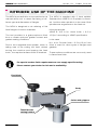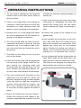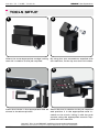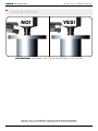
1
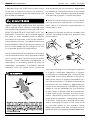
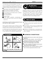
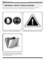
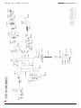
KRAIS Tube Expanders
QUALITY TUBE TOOLS
R E A D S A F E T Y R E G U L AT I O N S B E F O R E O P E R AT I N G T H I S T O O L
Manual Instruction
MFM
MANUAL FLANG MILL
|
R E A D
T H I S
M A N U A L
MFM Instruction Manual
C A R E F U L L Y .
K E E P
F O R
F U T U R E
U S E .
|
PAGE 1
KRAIS Tube Expanders
QUALITY TUBE TOOLS
1. Safety Recommendations.................................................................................................... 3
2. General Safety Regulations.................................................................................................. 6
3. Introduction ......................................................................................................................... 9
4. Intended Use Of The Machine .......................................................................................... 1 0
6. Machine Standard Equipment........................................................................................... 1 1
7. Machine Setup For Beveling.............................................................................................. 1 2
8. Operating Instuctions......................................................................................................... 1 5
.
9. Tools Setup........................................................................................................................ 1 7
10. Tool Breakdown............................................................................................................... 1 9
PAGE 2
WWW.KRAIS.COM
KRAIS Tube Expanders
QUALITY TUBE TOOLS
SAFETY RECOMMENDATIONS
For your safety and the safety of others, read
and understand the safety recommendations
and operating instructions before operating
this tool.
ALWAYS WEAR PROTECTIVE EQUIPMENT:
For additional information on eye and face
protection, refer Federal OSHA Regulations,
29 Code of Federal Regulations, Section
1910.133., Eye and Face Protection, and the
American National Standards Institute, ANSI
A87.1, Occupational and Educational Eye and
Face Protection. Z87.1 is available from the
American National Standards Institute, Inc.,
1430 Broadway, New York, NY 10018.
Hearing protectors are required in high noise
areas, 85 dBA or greater. The operation of
other tools and equipment in the area, reflective surfaces, process noises and resonant
structures can substantially contribute to, and
increase the noise level in an area. For additional information on hearing protection, refer to Federal OSHA Regulations, 29 Code of
Federal Regulations, Section 1910.95, Occupational Noise Exposure, and American National Standards Institute, ANSI S12.6 Hearing
Protectors.
Our tools are designed to operate on 90 psig
(6.2 bar) maximum air pressure. If the tool is
MFM Instruction Manual
properly sized and applied, higher air pressure is unnecessary. Excessive air pressure
increases the load and stresses on the tool
parts, which may result in cage, mandrel or roll
breakage. Installation of a filterregulator - lubricator in the air supply line ahead of the tool
is recommended.
Before the tool is connected to the air supply, check the throttle for proper operation
(i.e., throttle moves freely and returns to the
closed position). Clear the air hose of accumulated dust and moisture. Be careful not to
endanger adjacent personnel. Before removing a tool from service or changing sockets,
make sure the air line is shut off and drained
of air. This will prevent the tool from operating
if the throttle is accidentally engaged.
It is essential for the safe operation that the operator of the machine use good balance, sure
footing, and proper posture in anticipation of
the torque reaction. Insure that the operator’s
hand will not be wedged or pinched between
the work and the tool when operating.
When using right angle tool, be sure the throttle is positioned relative to the angle head
so that the throttle will not become wedged
against an adjacent object in the „ON” position due to torque reaction. The angle head
may be repositioned with respect to the lever
to accommodate proper location for the task.
If tool is to be reversed, locate throttle lever in
a neutral position that will prevent entrapment.
Refer to operating instructions for additional
information.
Tools with clutches can stall rather than shut-off
PAGE 3
KRAIS Tube Expanders
if adjusted over the maximum power output
of the tool, or if there is a drop in air pressure.
Operator must then resist the stall torque until
the throttle is released.
Higher torque right angle tools are supplied
with a splined torque reaction mounting plate
and reaction bar complete. ALWAYS USE WITH
REACTION BAR DEVICE SUPPLIED WITH THE
MACHINE! These bars can be braced against
the work or other suitable points to absorb
and relieve the operator of the torque reaction
transmitted by the tool. Tool balance arms are
also available to absorb the torque reaction of
the tool while balancing the weight of the tool
for improved ergonomic applications.
QUALITY TUBE TOOLS
and tendonitis can be caused or aggravated
by repetitious, forceful exertions of the hands
and arms. These disorders develop gradually
over periods of weeks, months and years.
Tasks should be performed in such manner
that the wrists are maintained in a neutral position, which is not flexed, hyperextended, or
turned side to side.
Stressful postures should be avoided and
can be controlled through tool selection and
work location.
Some individuals are susceptible to disorders
of the hands and arms when exposed to tasks
which involve highly repetitive motions and/or
vibration. Those individuals predisposed to
vasculatory or circulatory problems may be
particularly susceptible. Cumulative trauma
disorders such as carpal tunnel syndrome
Any user suffering from prolonged symptoms
of tingling, numbness, blanching of fingers,
clumsiness or weakened grip, nocturnal pain
in the hand, or any other disorder of the shoulders, arms, wrists, or fingers is advised to consult with a physician. If it is determined that the
symptoms are job related or aggravated by
movements and postures indicated by the job
design it may be necessary for the employer
to take steps to prevent further occurrences.
These steps might included, but are not limited to, repositioning the work piece or redesigning the workstation, reassigning workers
to the jobs, rotating jobs, altering work pace,
and/or changing the type of tool used so as
to minimize stress on the operator. Some
tasks may require more than one type of tool to
obtain the optimum operator/ tool/task relationship.
PAGE 4
WWW.KRAIS.COM
QUALITY TUBE TOOLS
The following recommendations will help reduce or moderate the effects of repetitive work
motions and/or extended vibration exposure:
Use a minimum hand grip force consistent
with proper control and safe operation.
Keep wrists as straight as possible.
Keep body and hands warm and dry.
Avoid anything that inhibits blood circulation.
Smoking Tobacco
Cold Temperatures
Certain Drugs
Avoid highly repetitive movements of
hands and wrists, and continuous vibration
exposure.
ADDITIONAL SAFETY RECOMMENDATIONS
FOR USE OF RIGHT ANGLE
Follow good machine shop practices. Rotating shafts and components can entangle and
enwrap, and can result in serious injures. Never wear long hair, loose-fitting clothes, gloves,
ties, or jewelry when working with or near a drill
or any machine with exposed rotating shaft.
KRAIS Tube Expanders
Drilling or other use of this tool may produce
hazardous fumes, particles, and/or dust. To
avoid adverse health effects utilize adequate
ventilation and/or a respirator. Read the material safety data sheet of any cutting fluids or
materials involved in the drilling process.
Attach the shaft and the cutter securely to
the PM to prevent the machine from jumping off work.
High reaction torque may be experienced
by the operator when reversing tool to remove the expander.
Machine or accessories not centered properly in the chuck can cause excessive wobble or vibration.
WORKING CONDITIONS
The MFM shall only be used in the following
conditions:
Make sure the opreator / user of MFM has
read and understood the User Manual
All Safety precautions are fulfilled .
There is no dammage to the MFM
No other condition to disturb normal working of the Minifacer applies.
Maintenance and cleaning shall be taken
care off and respected before all use.
MFM Instruction Manual
PAGE 5
KRAIS Tube Expanders
QUALITY TUBE TOOLS
GENERAL SAFETY REGULATIONS
KRAIS machines conform to EEC Work Safety Directives 89/392 (and further updating).
Make sure that the operator acts in compliance with the following indications:
Always work with: gloves and goggles.
NEVER set the machine when the power is on.
The Operating Manual and the machine
drawings will always provide quick and
specific explanations.
PAGE 6
WWW.KRAIS.COM
QUALITY TUBE TOOLS
The applicable standards and regulations are
set out in the CE declaration of conformity.
The authorized operator must in all cases
abide by basic safety rules, for example:
-- use gauntlets and goggles (PPE – personal
protective equipment provided by the company in charge of the workplace),
-- make sure that there is sufficient space
around the work area (at least 1,5 metres
around the operator),
-- make sure that there is sufficient lighting
around the work area,
-- do not carry out movements that are not
specified by the manual,
-- grasp the machine firmly with both hands do not replace the motor control or blocking
system,
-- do not allow other persons into the operating area,
KRAIS Tube Expanders
-- do not replace parts with non-original spare
parts,
-- do not direct jets of water at the machine,
-- do not allow the machine to come into contact with water or other liquids,
-- do not allow salt water to corrode the machine; put it back in its box at the end of the
work session,
-- remove chippings (swarf) with the appropriate instruments,
-- do not place hands anywhere near sharp
edges.
KRAIS emphasises that for all the operations
that are not specified.
DO NOT TRY TO INTERPRET INSTRUCTIONS AND DRAWINGS!
KRAIS technical service is at your complete disposal for any
further clarification
KRAIS also emphasises that it is FORBIDDEN to remove or replace the CE declaration of conformity
plate. The customer is requested to inform the manufacturer if the plate is tampered with.
KRAIS also declares that the machine has been subjected to testing of the basic parameters
at its own assistance service. The test included noise measurements conducted by qualified
personnel that yielded satisfactory results. Owing to its weight, lifting machinery is not required
to move the machine. However, in order to facilitate the use of the machine in certain conditions (e.g. with piping/heat exchangers, tube bundles, etc) KRAIS supplies the lifting device
illustrated alongside. The machine is used to execute the welding preparatory operations of
pipes included in the machine nominal range. The beveling machine is inserted and locked
into position inside the pipe.
For bevelling, a tool is used whose components and shape vary according to the type of material that needs to be bevelled.
MFM Instruction Manual
PAGE 7
KRAIS Tube Expanders
QUALITY TUBE TOOLS
MACHINE RANGE
The internal clamping diameter range of the MFM is
From +/- l” to 6” => 24mm to 160mm (with the std supplied gripper clamps)
The facing diameter range of the MFM is
From 1” - to 14” => 24mm to 355mm
TRANSPORT RECOMMENDATIONS
The MFM is supplied in a sturdy hard plastic
compact carryy case. This case is suitable
for the transport of the MFM.
Do assure that the latches at the front of the
carry case are firmly closed before lifting,
moving, manipulating or carrying the case.
To protect the outside shell of the carry
case, it is recommended to cover the casy
in a bubble film or full covering box when
shipping.
Check after every transport that the case
is intact and no dammage has occured. In
case of any dammage ,replace the carry
case for safety reasons and to avoid loss of
tooling.
All periferical tooling is also in this carry
case. All tooling has a propper place in the
box (cutout spaces foreseen) and is therewith clearly visible for the user.
Weight of the Machine
During transporting the MFM case shall be
fixed as load . Never put any heavy stuff on the
MFM thus to avoid dammage of the tool and
the carry case.
Shipping Dimensions
Shipping Weight
Under 25 Kgs no lifting machines are required.
STORAGE
Always store the MFM in a dry and clean
place.
After every use dry and clean the MFM with
a clean cloth. Make sure that there is no
swarf or metal particles in or at the MFM because they can disturb the clamping aswel
as the movement for normal operation. Remove the clamping spindle out of the hollow
center shaft center, clean, inspect and lubricate slightly with a smooth film of spindle oil
and put back into position.
PAGE 8
Then inspect to tool for eventual dammage
or loose parts (e.g. bolts) etc (If any loose
parts repair or send to your agent for repair)
After cleaning and inspection, lubricate the
slides and spindle with a film of spindle oil,
never use WD-40 or similar.
If stored for long term, then spray the MFM
with a protective spray layer such as Molykote 321D. Never use WD-40 or similar.
WWW.KRAIS.COM
QUALITY TUBE TOOLS
KRAIS Tube Expanders
INTRODUCTION
This Manual Instruction is a guide for using the
Manual Flang Mill bevelling machine.
TO REDUCE THE RISK IF INJURY AND EQUIPMENT DAMGE USER MUST READ AND UNDERSTAND OPERATING MANUAL.
We recommend you to keep the Manual Instruction always at hand while operating. The
content of this Manual Instruction may be partially different from the details of the product
actually purchased due to the result of our
constant research and improvement on the
design of the tool. Contents of the manual are
subject to change without notice due to improvement of the tool’s design.
Please do not start the bevelling work until you
read and adequately understand all safety instructions within this manual.
The Operational Instructions safety shown in
this Instruction Manual are applicable only to
the cases where the MFM is used for its intended purpose. If you operate the MFM by
method not described in this Manual the operator does so at their own risk.
MFM Instruction Manual
The safety instructions are emphasized in this
Instruction Manual by indicating “Warning” and
“Caution” according to the following definition to
prevent the injuries to human body and damage of property; so please understand them
adequately before using this machine.
The cases where the possibility of death or serious injury is assumed if there is an error in
handling.
The cases where the possibility of human
damage or only the damage of property is assumed.
PAGE 9
KRAIS Tube Expanders
QUALITY TUBE TOOLS
INTENDED USE OF THE MACHINE
The MFM is per definition not a machine but a
manual driven tool to obtain flat facing of different type and diameters of flanges.
The MFM is desgined to do refacing of flat
face flanges of various materials.
The tool provides in a grammophone finish
thus to create optimum gasket contact and
gasket seating conditions.
Due to the integrated feed spindel, which is
taking care of the cutting tool feed, whilest
turning the machine and keeping the feed
knob , the required surface finish is obtained.
The MFM is supplied with 2 feed spidels.
Standard the ASME B 16.5 spindle is mounted. And the other spindle is in the case. Both
spindles are engraveed on the feed nut.
Mounted spindle:
ASME B 16.5 is for “stock frnish = 6.3 to
12.5μm” according to ASME specification
In the case
Nr 1 is for “Smooth finish = 3.2 to 6.3 μm” this
finish is used for other types of flanges and
gaskets
These surface conditions are commonly used
in flanse face finish.
For special surface finish requirements we can supply specific tooling.
Please contact your dealer for info and or availability.
Feed Knob
Body
Collet with grippers
Toolslide with
cutting holders
PAGE 10
WWW.KRAIS.COM
QUALITY TUBE TOOLS
KRAIS Tube Expanders
MACHINE STANDARD EQUIPMENT
The machine is supplied with:
Service Tools
Case
Instruction Manual and expoloded drawings
Service Tools
MFM
Manual Flang Mill
Case
Operating and instruction
manual and drawings
MFM Instruction Manual
PAGE 11
KRAIS Tube Expanders
QUALITY TUBE TOOLS
MACHINE SETUP FOR BEVELING
1
Before proceeding with the machine settnig,
verify the measure of the pipe you are going
to bevel and select the most suitable locking
segments.
Screw out and remove the SEGMENTS
LOCKING PLUG
2
3
Screw tight the SEGMENTS EXPANSION
NUT
Remove the three SEGMENTS
DO NOT TRY TO INTERPRET INSTRUCTIONS AND DRAWINGS!
KRAIS technical service is at your complete disposal for any further clarification
PAGE 12
WWW.KRAIS.COM
KRAIS Tube Expanders
QUALITY TUBE TOOLS
MACHINE SETUP FOR BEVELING
4
DO NOT REMOVE THE EXPANSION SHAFT!
Move it by using the SEGMENTS EXPANSION
NUT after re-assemblying the segments.
Choose the SEGMENTS on the basis of the
inside diameter of the pipe to be bevelled
and assemble them as shown in the figure.
5
Keep the three SEGMENTS with one hand
and screw out the SEGMENTS EXPANSION
NUT (Part no. 38) to make them recess. If
the assembly has been properly carried
out, the three segments must have a slight
clearance in their seat.
MFM Instruction Manual
6
Re-screw tight the SEGMENTS LOCKING
PLUG
PAGE 13
KRAIS Tube Expanders
QUALITY TUBE TOOLS
MACHINE SETUP FOR BEVELING
7
8
Insert the machine SHAFT into the pipe.
By keeping the machine in line with the pipe,
tighten the SEGMENTS EXPANSION NUT.
Insert the three SEGMENTS into the pipe by
about 15 ÷ 20 mm.
DO NOT TRY TO INTERPRET INSTRUCTIONS AND DRAWINGS!
KRAIS technical service is at your complete disposal for any further clarification
PAGE 14
WWW.KRAIS.COM
KRAIS Tube Expanders
QUALITY TUBE TOOLS
OPERATING INSTRUCTIONS
1. Fit the correct spindle for the required
surface finish in the MFM (stock finish or
Smooth finish)
2. Check if the inside diam of the flange to
machine is clean and does not show any
obstruction or other elements that can
disturb correct clamping of the grippers.
3. Measure the “id” of the flange and select
the correct segments for the internal diameter of the flange to machine.
6. Turn the knurled knob by hand (counterclockwise) and push it down so that the
segments are in its smalest diam position, but avoid that the clamps are not in
the groove.
7. The MFM is now ready to be fit into the
bore of the flange.
8. Place the center shaft with the segments
into the bore of the flange, keep the fingers around the clamping shaft and
smoothly slide the clamps down into the
bore. Position the segments approx 1520 mm lower then the face of the flange.
toolslide so that the cutting tip faces towards you.
11.Now lift the turning (Alu knob with finger
indentions) to disengage the feed and
postion the cutting tool with the handwheel towards the inside of the flange to
face.
12.Position the toolbit in the middel of the
gasket area.
13.Now release the fixing bolt on the toolport, and feed down the cutting tool so
that it just contacts the metal face. Then
tighten the fixing bolt on the toolport
again. Position the cutting tool further inwards, until it has gone over the metal to
machine ( I.e. in a position that it is free)
14.Now engage the feed by bringing the Alu
knob down. Grab the Alu know with your
hand and turn round counterclock wise .
The feed is now bringing the cutting tool
automaticaly from inside to outside
9. Turn the knurled knob clockwise so the
clamps go out and start to clamp into
the bore. Whilest turning the knob slightly
move the MFM so that the centering is
optimal. When the MFM is in place, use
the 19 mm spanner (on the HEX on top
of the knob) to firmly tighten the MFM in
place.
10.Place the cutting tool into the toolport .
Check the cutting tip and replace if necessiary. Assemble the toolport onto the
MFM Instruction Manual
PAGE 15
KRAIS Tube Expanders
QUALITY TUBE TOOLS
OPERATING INSTRUCTIONS
DO NOT STOP TURNING WHEN THE CUTTING TOOL IS MACHINING AND NEVER
TURN INTO THE OPOSITE DIRECTION.
Otherwise the surface finish is not even and
the cutting tip might break of.
If the whole area is not touched ,lift aluminium knob again, turn the cutting tip to the
inside, release the fixing bolt on the toolport,
turn the cutting tip down for 11/12 revolution
(equals +/- 0.1 mm downfeed). And repeat
the machining operation.
Repeat this until the whole gasket area is
done.
15.Turn until the cutting tip is over the metal
to machine (outside the gasket face)
16.When the operation is done and the gasket face is evenly machined, the job is
ready
17.To take the MFM out of the flange, remove
the toolport (Alan bolt), then release the
hex (19 mm) center knurled knob. Then
support the MFM with your hand and tap
the center shaft with the plastic hammer.
then the clamps will come loose and the
minifacer can be taken out of the bore.
PAGE 16
WWW.KRAIS.COM
KRAIS Tube Expanders
QUALITY TUBE TOOLS
TOOLS SETUP
1
2
Select the most appropriate wedge locking
tools kit in relation to the job required.
3
By using the torx screwdriver supplied with
the machine, fix the tip onto the tool holder.
4
Insert the Holder in the appropriate seat as
shown in the above picture.
Select the tool in relation to the job required
and position it in the appropriate seat located on the chuck, loking it with the grub
screws using the appropriate wrench supplied with the machine.
DO NOT TRY TO INTERPRET INSTRUCTIONS AND DRAWINGS!
KRAIS technical service is at your complete disposal for any further clarification
MFM Instruction Manual
PAGE 17
KRAIS Tube Expanders
QUALITY TUBE TOOLS
TOOLS SETUP
NO!
YES!
ATTENTION! ASSEMBLE THE TOOLS AS SHOWN IN THE FIGURE!
DO NOT TRY TO INTERPRET INSTRUCTIONS AND DRAWINGS!
KRAIS technical service is at your complete disposal for any further clarification
PAGE 18
WWW.KRAIS.COM
MFM #6
MFM #5
MFM #8
MFM Instruction Manual
MFM #10
MFM #11
MFM #4
MFM - TOOL BREAKDOWN
MFM #12
MFM #9
MFM #3.1
MFM #2
MFM #3.2
MFM #45
MFM #44
MFM #42
MFM #41
MFM #16
MFM #3.3
MFM #7
MFM #13
MFM #1
MFM #46
MFM #43
MFM #40
MFM #39.1
MFM #14.1
MFM #15
MFM #17
MFM #19
MFM #20
MFM #21
MFM #29
MFM #28
MFM #14.2
MFM #18
MFM #27
MFM #22
MFM #23
MFM #30
MFM #31
MFM #24
MFM #32
MFM #25
MFM #33
MFM #26
MFM #34
MFM #35
MFM #36
MFM #38
QUALITY TUBE TOOLS
KRAIS Tube Expanders
PAGE 19
Warranty
KRAIS guarantees the efficient operation of its products subject to the following terms and conditions.
The warranty covers any machine production faults for a period of one year from the date of delivery to the user (see delivery note).
Parts that are subject to wear and tear are excluded from the warranty at the sole discretion of KRAIS. If operating faults are discovered
during the warranty period, KRAIS or the approved Distributor, shall remedy the fault without charging the user for labour costs or
spare parts provided that the defect is not directly or indirectly due to incorrect use or tampering.
The machine must in all cases not have been even partially disassembled or tampered with when it is delivered. The warranty is valid
only if the certificate has been countersigned by KRAIS. and has been countersigned by an official KRAIS. The delivery of material
on which the fault has been found must be made within 8 (eight) days from the date of notification of the fault and/or complaint and/
or request for technical assistance. Otherwise, all warranty rights are voided.
KRAIS obligations concern only the repair of the fault and the general maintenance and testing of the material in object. The component replacement is at the sole discretion of KRAIS.
The costs of the forwarding to and from Distributor as well as the costs directly or indirectly due to the product repair are at the
user’s charge. Any interventions under warranty or any extraordinary maintenance must be executed by KRAIS or by any authorized
Distributor; otherwise the warranty rights are voided. Any non-routine maintenance carried out by the customer/user or by technical
assistance centres that have not been approved by KRAIS will not be refunded and will immediately void warranty rights.
The warranty is not valid for cases that are not specified by this certificate or for damage caused by incorrect use of materials, incorrect feeding, operators’ negligence, unauthorised odifications, atmospheric agents, act of vandalism, damage due to improper
handling and/ or transportation, use of spare parts that are not original KRAIS spare parts.
KRAIS reserves the right to modify and improve its products without being under any obligation to modify the equipment and components already supplied. Nobody is authorised to modify the conditions contained in this certificate or to issue any others in the name
of KRAIS. The customer has 8 (eight) days from the date of delivery within which to lodge complaints about faults and/or defects
in the ordered material and quantities delivered and if he accepts delivery he automatically accepts the above warranty conditions.
WARRANTY CERTIFICATE
Model
Pneumatic feeding Power feeding
Serial No.
Code
Testing date
Tech. Dept. Signature
Testing ref
KRAIS Signature
Sales data
For foreign distributors only
Distributor
Sales Dept. Signature
Poland, 55-106 Zawonia, Czachowo 15
tel. +48 71 312 05 96, fax +48 71 387 03 32
www.krais.com [email protected]