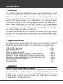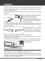
1
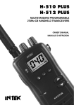
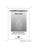
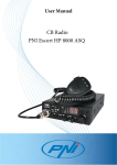
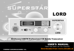
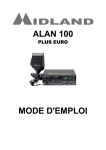
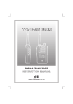
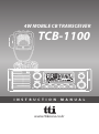
4W MOBILE CB TRANSCEIVER
TCB-1100
I N S T R U C T I O N
M A N U A L
www.ttikorea.co.kr
Our Thanks to You and Customer Assistance
Our Thanks to You
Our Thanks to You
Thank you for purchasing a TTI CB TRANSCEIVER radio.
Properly used, this TTI product will give you many years of reliable service.
All our products are built to offer excellent value by combining
advanced features, great design and manufacturing quality.
To ensure you are familiar with the operation and features of your
radio, and in order to obtain the best performance, please read
this manual carefully before operation.
2 English
TCB-1100
Contents
Contents
1. Introduction ........................................................... 4
2. Supplied Accessories................................................4
3. Installation ............................................................ 4
4. Transceiver Controls and Functions ............................ 7
(1) Front Speaker .................................................... 8
(2) Channel Selector ................................................ 8
(3) LCD Display ...................................................... 8
(4) Volume & Power On/Off Knob ........................... 8
(5) Microphone Jack ............................................. 8
(6) Mode & LCR & Memory Button .............................9
(7) Backlighting & Lock Button ............................... 9
(8) Compander & Tone Button ................................ 9
(9) Dual Watch & Vox Button..................................9
(10) Scan&Scan Memory Button .............................10
(11) Emergency Channel(9/19) & Menu button ....... 11
(12) Squelch & DSS Knob .................................... 12
(13) Antenna Connector.......................................... 12
(14) S-Meter ......................................................... 12
(15) EXT Jack ....................................................... 12
(16) Power 13.2V DC ........................................... 12
5. LCD Display ......................................................... 13
6. Microphone .......................................................... 13
7. How to operated the Transceiver ........................... 14
8. Band Selection ...................................................... 14
9. Trouble Shooting ..................................................... 15
10. CE Declaration ................................................... 16
11. Safety Requirement ........................................... 16
12. Specifications ................................................... 17
13. Restrictions on the use ....................................... 18
14. Frequency Table
TCB-1100
English 3
Introduction
1. Introduction
TCB-1100 transceiver is designed to have a good performance in any
conditions that the transceiver operates, using rugged build chassis,
PCB’s and components. This transceiver is also designed for users’
convenience, implementing human ergonomics to locate the knobs and
buttons in the proper places. The combination of well designed knobs
and buttons as well as user friendly graphic layouts will lead users to
quickly adapt themselves for the easy operation. The newly applied
menu mode will make professional users more satisfactory with pleasure. The elegant, luxury and different colored LED light supporting the
face design will go well with any vehicles.
This instruction manual has been designed to enable you to get the best
use from your CB Transceiver, therefore you are recommended to take a
few minutes to read this instruction manual before initial use of your CB
Transceiver.
2. Supplied Accessories
Your transceiver is supplied with a full range of accessories to help you
get started and virtually benefit from all the features straight away.
TCB-1100 Transceiver
Microphone with cord
Power cable
Radio mounting bracket
Radio mounting thumb screw with rubber washer
Mounting screw with washer(for transceiver bracket)
Mounting screw with washer(for microphone bracket)
Microphone mounting bracket
Din Front Plate
Din Body Plate
1 unit
1 unit
1 unit
1 unit
2 pieces
3 pieces
2 pieces
1 piece
1 unit
1 unit
3. Installation
Normal Installation using Mounting Bracket
Plan the location of the transceiver and microphone first, which is most
convenient for the operation. The transceiver should normally be mounted horizontally, but may be mounted vertically. The bracket supplied can
be fitted above or below the case allowing the TCB-1100 to be cradled
by the bracket or suspended from it.
4 English
TCB-1100
Installation
Consider that this location of the transceiver should not interfere with the
driver and passengers. Choose a spot where the microphone and all controls are easily accessible.
1) Put the mounting bracket on the proper location where you are going
to install.
2) Drill holes and fix mounting
bracket on the location.
3) Connect the antenna
cable plug to the standard receptacle on the transceiver, which is
marked “ANT”.
4) Connect the power cable directly to the vehicle battery or fuse box of
the car. Be careful to make sure of the polarity of the battery first and
connect the cable.
(Red: Positive Pole(+), Black:
Negative Pole(-). The same colors are shown on the battery
and in the fuse box of the car.)
5) Connect the power cable to the transceiver cable.
6) Mount the microphone bracket on one side of the transceiver, or near
it using two screws included.
7) Connect the microphone to the transceiver’s microphone receptacle.
Now you are ready to operate
the transceiver.
Installing into Audio Compartment
This transceiver is also designed to have the DIN size to be directly
installed into the audio compartment of your vehicle.
For this purpose, use the TTI supplied installation supporting DIN plates.
All other connections and installations are same as the above “Normal
Installation Using Mounting Bracket.”
TCB-1100
English 5
Installation
1) Install the Din-Body plate into the audio compartment (center fascia)
of your vehicle.(Use the ready made locking flaps.)
2) Set the transceiver in the Din-Front plate, and insert the transceiver
in the Din-Body plate.
3) Fix the screws through
the transceiver, Din-Front
plate and Din-Bodyplate.
Din-Body Plate
Din-Front Plate
CB Radio
Screw
Installing an Antenna
It is very important to select a good quality high efficiency 27MHz
antenna. A poor quality antenna or one not designed for the 27MHz
band will give very poor performance and could cause damage to the
transceiver.
1) Place the antenna as high as possible.
2) The longer the antenna is, normally the better is the performance of
the transceiver.
6 English
TCB-1100
Transceiver Controls and Functions
3) Try to mount the antenna in the centre of the surface that you select.
4) Make sure that you have a solid metal-to-metal ground connection.
5) Be careful not to damage the cable during the installation.
Warning : Never try the operation of your transceiver before connecting
a proper antenna in order not to cause any damage.
4. Transceiver Controls and Functions
1 Front Speaker 2 Channel Selector 3 LCD Display
4 Volume/Power Knob
Microphone Jack 5
3
1
Squelch/DSS Knob 12
Emergency Channel 11
/ Menu Button
Scan/ Scan Memory
Button 10
MHz
SIG
PWR
6 Mode/LCR/Memory
Button
7 Backlight/Lock Button
8 Compander/Tone Button
9 Dual Watch/Vox Button
Antenna Connector 13 S-Meter 14
EXT Jack 15
Power 13.2V DC 16
TCB-1100
English 7
Transceiver Controls and Functions
Front Speaker
Channel Selector
1) Front Speaker
The front speaker makes the audio always loud
enough even when the transceiver is located in
the audio compartment (center fascia) or in some
places difficult to be found.
2) Channel Selector
Turn right or left, and this allows you to select the
channel one by one that you like to use. For the
quick channel up/down, momentarily press this
selector, and the channel display will blink. Then
turn right or left, which will allow you to use the
quick channel up or down function. Using this
function, the channel numbers will move by 10
channel steps.
LCD Display
3
MHz
1
Volume&Power Knob
Microphone Jack
Mode & LCR button
8 English
SIG
PWR
3) LCD Display
Most of the operational information is displayed. Please see item no.5 LCD Display for
the details of information.
4) Volume & Power On/Off Knob
To switch on the transceiver turn this knob clockwise. After clicking sound the transceiver is
switched on. The more you turn this knob clockwise, the bigger the audio sound grows.
5) Microphone Jack
Insert the microphone into this jack. Use the guide
for easy connection.
6) Mode & LCR & Memory Button
Mode and LCR : When the transceiver is used in
UK,UE,EC,D or D2 frequency band modes this
button activates Last Channel Recall function.
In all other modes (where national regulations
TCB-1100
Transceiver Controls and Functions
permit this), this button allows the user to switch
between AM and FM modes by momentarily pressing this button.
Memory : Pressing and holding this button lead the user to the memorized channel which has been selected in the Menu mode.“MEM” is on
in the LCD display.
Backlighting&Lock Button
Compander&Tone Button
7) Backlighting & Lock Button
Backlighting : Three colors are available for user
selection. The colors include amber, green and
blue. Momentarily press this button to change the
color.
Lock : Press this button for more than 2 seconds
to activate and deactivate the keypad lock function.
“Lock” is on in the LCD display. The volume knob,
squelch knob and 9/19 button are working normal
even while the Lock is activated.
8) Compander & Tone Button
Compander on/off : Advanced compander circuit is
embedded in the transceiver to allow crystal clear audio
sound. To activate this compander circuit momentarily press this button. “COMP” is on in the LCD display.
Tone on/off : CTCSS tone is selected and activated
in the MENU mode. Pressing and holding the button lead users to deactivate or activate the selected
tone code.
Dual Watch & Vox Button
TCB-1100
9) Dual Watch & Vox Button
Dual Watch : Press momentarily this button
while you are on the current (primary) channel. The dual watch icon “DW” blinks. Turn
the channel knob to select another(secondary)
channel that you like to monitor. The dual
watch icon “DW” stops blinking and the dual
watch starts between the selected(secondary)
channel
and
the
primary
channel.
If you like to change the selected (secodndary)
English 9
Transceiver Controls and Functions
channel, just turn the channel knob to select a new one. You may select
the emergency channel. To stop this function, press momentarily again
this button.
If you press the PTT button whilst receiving a signal in dual watch mode
the transceiver will transmit on the currently displayed channel.
will transmit on the currently displayed channel. If you press the PTT
button when no signal is present the transceiver will transmit on the
primary channel.
VOX : Press and hold this button, and this will allow you to use vox function. “VOX” is displayed. The Vox level is pre-selected and memorized
in the MENU mode.
Scan / Scan Memory
10) Scan & Scan Memory Button
Scan : Press this button momentarily to start scanning upward to catch any channels that are occupied by others.
To activate/deactivate the channel scan, press the Scan button briefly.
The Scan icon will appear when the channel scan is active. Scanning
will only stop when you deactivate the scan function.
Turn the channel selector counter-clockwise during scanning in order to
change the scanning direction.
The transceiver will scan through the whole transceiver channels. If
your transceiver detects a valid signal the scan will pause for the period
that has been set by the menu mode setting (continuously receiving or
1-99 seconds for scan receive time and immediate response or 1-99
seconds for scan delay time).
If you press the PTT button when your transceiver detects a signal, the
radio will transmit on the same channel. Scanning will resume after the
scan receive time and/or the scan delay time. Use the channel selector
to resume scanning immediately.
Scan Memory : It is possible to memorize or erase any channel(s) in
the scan memory list. When a channel or channels are contained in
the scan memory list, the channels are scanned by the scan activation
For user convenience, all the channels are memorized in the list upon
shipment from the factory, and “M” is displayed with the memorized
channels. To erase the displayed channels from the scan memory list,
press and hold the button.
10 English
TCB-1100
Transceiver Controls and Functions
11) Emergency Channel(9/19) & Menu Button
Emergency Channel(9/19) : Pressing this button
will lead you to the emergency channel, “CH9(or
CH19)” and the EMG icon will be displayed. Only
the squelch knob and volume knob will work. To return to the previous operation mode, momentarily
press the emergency button again.
MENU : The menu mode allows you to set-up and edit the selectable functions. To access the MENU mode, press and hold this button, and afterwards each press of the MENU button steps the transceiver sequentially
through the different functions. The LCD display indicates the current function. The present setting and associated icons flash.
Use the channel selector to change the setting. Press the PTT or MENU button or wait for about 10 seconds to store your choice. If you do not press
any button or knob for about 10seconds, your transceiver will return to the
stand-by mode automatically.
EMG & MENU Button
Display
Functions
Settings
CTCSS TONE SELECTION
(Receive)
01-38 and off(
)
CTCSS TONE SELECTION
(Transmit)
01-38 and off(
)
VOX Level Selection
Beep Tone
On(
), Off(
)
Call Tone
01-05 and Off(
)
Time-out Timer
1-99 s ec., Off(
)
Scan Receive Timer
Scan Delay Timer
(after receiving signal)
Backlight Dimmer and off
Channel Memory
TCB-1100
01,02,03
Continue(
), 1-99sec.
1-99 s ec, Off(
High(
Off(
), Low(
)
),
)
01-40
English 11
Transceiver Controls and Functions
Note:
1. Use the channel selector to select the main MENU feature values such
as tone numbers, VOX levels and etc.
2. Press Lock button or PTT button of the Microphone to complete the
selections and changes and return to the stand-by mode. Or the selections and changes will be automatically confirmed after 10 seconds of
the selections and changes.
Squelch & DSS Knob
12) Squelch & DSS Knob
Manual Adjustment : Turn this knob counterclockwise until you hear the background noise and
then turn the knob a little clockwise until the noise
disappears. In this way, you get the best receive
sensitivity.
DSS: In FM mode turn the knob counter-clockwise
until you hear the click. The squelch level of your
transceiver is dynamically adjusted.
Antenna Connector
13) Antenna Connector
Insert the male connector of the antenna cable into
this female antenna connector.
S-Meter
14) S-Meter
Connect an external S-Meter (This is not supplied)
to this port.
EXT Jack
15) EXT Jack
Connecting a loud speaker (This is not supplied) to
this port makes the built-in speaker turned off.
Power 13.2V DC
12 English
16) Power 13.2V DC
Connect the power supply cable to this port.
TCB-1100
LCD Display & Microphone
5. LCD Display
Scan Memory
Scan
Emergency Channel
Dynamic Squelch
System
CTCSS Tone
Selected Frequency
Band
Channel
Frequency
Read-outs
3
1
Signal Strength
Meter
External Speaker
External S-Meter
MHz
SIG
Low Power
VOX
AM Mode
FM Mode
Transmit
Dual Watch
Compander
PWR
Keypad Lock
Channel Memory
Speaker Mute
( Using Microphone Lock Button)
6. Microphone
1 Up Button : Use this button to change the
channels upward.
2 Down Button : Use this button to change the
channels downward.
3 Mute and Lock Button : Press and hold the
button. This locks the up button and down
button of the microphone. Also, this lock
works same as the lock button on the transceiver front panel.
Momentarily press the button to make mute
the speaker of the transceiver.
4 PTT Button : While pressing this button, you
can transmit.
5 6 Pin Microphone Connector :
Connect this to the microphone jack on the
front panel of the transceiver.
TCB-1100
English 13
Band Selection
7. How to operate the Transceiver
1) Make sure the microphone is connected to the microphone jack.
2) Make sure the power cable is connected properly.
3) Make sure the antenna is connected to the antenna receptacle.
4) It is better to put the squelch control knob turned fully counter-clockwise.
5) Turn on the transceiver and control the volume level.
6) Adjust the squelch control knob to the optimum level.
7) Select your desired channel.
8) To transmit, press the PTT button and speak to the microphone.
9) Release the PTT button to receive.
8. Band Selection
Band Selection
+
Setting
EC
Pressing “MO/LCR” button of transceiver, turn on
the transceiver. Using the channel selector, select
the band that you are going to select. The LCD
display offers you the band information. The band
chart for each area is as follows.
Press the PTT button of “MO/LCR” button to confirm the selection and to return to the stand-by
mode.
This transceiver has “EC” band setting when it is
shipped out from the factory.
Display
Band
Europe 40 Ch FM 4W
E
Spain 40 Ch AM/FM 4W
F
I
France 40 Ch FM 4W, 40 Ch AM 1W
Poland 40 Ch sAM / FM 4W
(Polish Frequencies : 5KHz)
UK 40 Ch FM 4W (British Frequencies)
UK 40 Ch FM 4W (British Frequencies)
+CEPT 40Ch FM 4W(EC) + CEPT 40Ch FM
Italy 40 Ch AM / FM 4W
I2
Italy 34 Ch AM / FM 4W
PL
UK
UE(EU/UK)
D
Germany 80 Ch FM 4W, 12 Ch AM 1W
D2
Germany 40 Ch FM 4W, 12 Ch AM 1W
EU
Europe 40 Ch FM 4W, 40 Ch AM 1W
14 English
TCB-1100
Trouble Shooting
9. Trouble Shooting
If you experience problems with your TCB-1100 transceiver, first check
the power supply source. Poor connection of the power supply source
can cause problems such as no transmission, no reception or poor
reception, and weak or no sound. Ensure that the microphone and antenna are also well connected.
If this does not solve the problem, reset your transceiver as follows.
Trouble Shooting
+
1) Switch off the transceiver.
2) Pressing “9/19” buttons and turn the volume
knob clockwise.
This will reset the transceiver, so all the memories are erased and the parameters return to the initial factory setting.
This should fix most problems.
In case of further difficulty, Please consult your dealer or visit our website.
10. CE Declaration
CE versions of the TCB-1100 which display the CE
on the product label, comply with the essential
0700 symbol
requirements of the European Radio and Telecommunication Terminal Directive 1999/5/CE.
This warning symbol indicates that this equipment operates in non-harmonised frequency bands and/or maybe
subject to licensing conditions in the country of use.
Be sure to check that you have the correct version of this
radio or the correct programming of this radio, to comply
with your national licensing requirements.
This unit can be used without license and charges in; Austria, Belgium,
Bulgaria,Cyprus, Czech, Denmark, Estonia, Finland, France,Germanay,
Greece, Hungary, Iceland, Ireland, Italy, Latvia, Lithuania, Luxembourg,
Malta, Netherlands, Norway, Poland,Portugal,Pomania, Slovakia, Slovenia,
Spain, Sweden, Switzerland, and U.K.
11. Safety Requirement
The power cable is for 13.2V DC only. Be sure the transceiver is off
before connecting the leads of the power cable to the power supply. It
is important to observe the polarity even if the unit is protected against
the accidental inversion :
TCB-1100
English 15
Specifications
* Red : Positive pole (+)
* Black : Negative pole (-)
The same colors are present on the battery and in the fuse box of the car.
The unit must be wired for the negative ground only.
To avoid damage, do not operate your CB radio without connecting a
proper antenna.
12. Specifications
General
Channel
Frequency Range
Operating mode
Frequency Control
Frequency Tolerance
Operating Temperature Range
Microphone
Input Voltage
Size
Weight
Antenna Connector
40 (See the frequency band chart)
26.96 MHz ~ 27.99125 MHz
F3E (FM), A3E (AM)
PLL Synthesizer
0.002%
-10 to + 55 C
Plug-in Type
13.2V DC
15%
190(W) x 165(L) x 58(H)
978.5 g
SO-239 type
Transmitter
Power Output
Modulation
Frequency Respons e
Output Impedance
Harmonic Suppression
Current Drain
Receiver
Receiving System
IF Frequencies
Sensitivity
Audio Output Power
Audio Distortion
Image Rejection
Adjacent Channel Rejection
Conducted Spurious
Frequency Respons e
Built-in Speaker
Squelch
16 English
Duty cycle 10% 4 Watts @13.8V DC
AM:from 85% to 95%
FM:1.8KHz to +2.0KHz
300Hz to 3000Hz
50ohms, Unbalanced
Less than -36dBm
AM Full Mod. 1.6A Max.
Dual conversion superheterodyne
Double Conversion 1st 10.695MHz/ 2nd 455KHz
0.7 V for 10dB(S+N)/N in AM Mode
0.7 V for 20dB SINAD in FM Mode
2.0W @ 8 Ohm
Less then 8% @ 1KHz
60 dB
60 dB
Less than -57dBm
300 to 2500Hz
8 Ohms, round
Adjustable; Threshold less than 1 microvolt
DSS; Less than 2 microvolt
TCB-1100
Restrictions on the use
13. Restrictions on the use
Country
Settings
EU F
BELGIUM
SWITSERLAND
DENMARK,NORWAY
LUXEMBOURG,CZECH
EU F
FINLAND,PORTUGAL
FRANCE,NETHERLANDS
D
GERMANY
GREECE
IRELAND
ITALY
SPAIN
SWEDEN
UK
POLAND
TCB-1100
Use restrictions and other comments
EC 40Ch -4W FM- Individual License is required
40Ch -1W AM- Individual License is required
EC 40Ch -4W FM- Free Use
EC 40Ch -4W FM- Free Use
40Ch -1W AM- Free Use
80Ch -4W FM- Individual License is required
12Ch -1W AM- Individual License is required
EU
40Ch -1W AM- Use Ch 4-15 Only
D2
EC 40Ch -4W FM- Free Use
12Ch -1W AM- Individual License is required
fx Allowed: from 26.960 to 27.410 MHz “BAPT 222 ZV 104”
E EU F I EC 40Ch -4W FM- Free Use
40Ch -5W AM- Free Use
T/R 20-02
E EU F I EC 40Ch -4W FM- Free Use
40Ch -1W AM- Free Use
S.I.No 436 of 1998. WIRELESS TELEGRAPHY ACT, 1926 (SECTIONS)
(EXEMPTION OF CITIZEN’S’ BAND (CB) RADIOS) ORDERS, 1998
E EU F I EC 40Ch -4W FM- General authorisation is required
40Ch -1W AM- General authorisation is required
I2
34Ch -4W FM
34Ch -1W AM(ERP) *AM mode allowed on ch1-23 only
PNF issued on DM 08.07.02 NOTES 49 A-B-C-D-E-G
E EU F EC 40Ch -4W FM- Individual License is required
40Ch -4W AM- Individual License is required
Art. 57 - Law 11/1998 dated 24th April
EU F EC 40Ch -4W FM- Free Use
40Ch -1W AM- Individual License is required
UK
EC 40Ch -4W FM- Individual License is required
UK-RA-MPT 1382/MPT1320;UK-R&TTE - S.I.L. 2000:730
PL EU
EC 40Ch -4W FM/AM- Free Use
English 17
Declaration of Conformity
Declaration of Conformity
We, TTI Tech Co.,Ltd (TTI house, 1163-4, Gaepo-dong, Gangnam-gu,
Seoul, Korea) declare on our sole responsibility that this equipment
complies with the essential requirements of the Radio and Telecommunications Terminal Equipment Directive, 1999/5/EC, and that any applicable Essential Test Suite measurements have been performed.
Kind of Equipment : MOBILE CB TRANSCEIVER
Type-Designation :
TCB-1100
Version (where applicable):
This compliance is based on conformity with the following harmonized
standards, specifications or documents:
ETSI EN 301 489-13 V1.2.1
ETSI EN 300 135-2 V 1.1.1,
ETSI EN 300 433-2 V 1.1.2
EN 60950-1 : 2001+A11:2004
Seoul, Oct. 27, 2008
N. Y. Kim
Director
CE Marking
This radio is marked
0700
adjacent to the serial number.