1
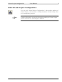
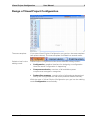
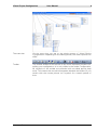
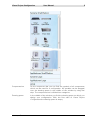
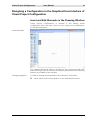
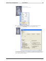
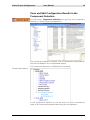
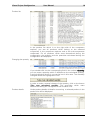
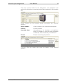
Visual Project Configuration - User Manual - Contents Introduction 1 Start Visual Project Configuration 2 Design of Visual Project Configuration 3 Outline of the Functions of Visual Project Configuration 6 Functions in the File Menu Functions for Adapting the Graphic Display The View Menu Functions in the Extra Menu The Window Menu The Help Menu Designing a Configuration in the Graphical User Interface of Visual Project Configuration Insert and Edit Elements in the Drawing Window View and Edit Configuration Results in the Component Selection Take Over Configuration Results into a Visual Project ® Offer 6 8 9 9 10 10 11 11 15 18 Visual Project Configuration User Manual 1 Introduction Visual Project Configuration is a configuration tool which is integrated in Visual Project ®. By means of this tool, single components of telecommunication and information technology systems can be compiled into an optimum solution. Its user-friendly, graphical interface enables the user to project different systems with low effort. Via „drag and drop“, the single components of the system can be selected and connected. Out of that configuration Visual Project Configuration determines all components which are necessary for the system. The configuration results can be taken over into an offer of Visual Project ® via pressing one button. Visual Project ® Revision 2013.12 Visual Project Configuration User Manual 2 Start Visual Project Configuration You can call Visual Project Configuration in the project editing of Visual Project ® via the menu <Config.-assistant> or by clicking onto the corresponding symbol. Further information concerning the project editing of Visual Project can be found in our Visual Project ® Manual. Visual Project ® ® Revision 2013.12 Visual Project Configuration User Manual 3 Design of Visual Project Configuration The start template If you start Visual Project Configuration you get into the start template (see picture above). The start template is divided into several areas: Selection bar for the editing mode Visual Project Configuration offers three different editing modes: Configuration, graphical interface for designing a configuration. Here the actual configuration is happening. Component selection, overview of all available system components arranged in categories. Product line summary, contains a list of all products determined during the configuration as well as all products added manually. With the start of Visual Project Configuration you get into the editing mode Configuration automatically. Visual Project ® Revision 2013.12 Visual Project Configuration User Manual 4 The menu bar Via the menu bar you get to the single menus of Visual Project Configuration. Depending on the editing mode, the menu options can differ. Toolbar The toolbar enables a fast access to the most important functions for editing your configuration. It is only visible in the mode Configuration. All symbols of the toolbar are provided with so-called pop-up help texts. This means that a small text appears beneath the buttons if you remain with the mouse pointer on a symbol for a certain period of time. Visual Project ® Revision 2013.12 Visual Project Configuration User Manual 5 Component bar On the component bar you can find the symbols of all components which can be used for a configuration. All symbols can be dragged onto the drawing space in the middle of the window by drag and drop. The component bar is divided into categories. Drawing space In the middle of the window you find the drawing space on which you design your configuration. With the first start of Visual Project Configuration the drawing space is empty. Visual Project ® Revision 2013.12 Visual Project Configuration User Manual 6 Outline of the Functions of Visual Project Configuration Functions in the File Menu The file menu offers different functions for saving, printing and exporting. New Open Opens a new, empty configuration file. Before that the currently opened configuration should be saved if necessary, otherwise changes which were carried out before will be lost. You can read in a configuration saved as xml file via the menu option <File/Open>. Since changes which were carried out previously will be lost, you should save your configuration if necessary. If you want to use your configuration for further projects, you can save it via the menu option <File/Save> or <File/Save as> in xmlformat. Save Save as Print options Visual Project ® Saves the currently opened configuration. Saves the currently opened configuration under a different name. For individual settings of the page layout you find the following options in the menu <File/Print options>: Paper size Choose the size of the document to be printed. Orientation Here you can determine the orientation of the page. Upper margin Shows the distance of the printable area from Revision 2013.12 Visual Project Configuration User Manual 7 the upper margin. Preview Print Export Visual Project ® Lower margin Shows the distance of the printable area from the lower margin. Left margin Shows the distance of the printable area from the left margin. Right margin Shows the distance of the printable area from the right margin. Show date/time Determines whether date and time should be printed on the scheme. Show page number Determines whether the page number should be printed on the scheme. With border Determines whether the border should be printed on the scheme. Fit to Page Fits the whole drawing into one page. Set as standard Sets the determined settings as standard. Restore standard Restores the settings which were saved as standard. Shows the graphical scheme in the page preview. The page preview can be reached via the menu option Preview and, if necessary, settings for printing can be changed. Via the menu option <File/Print> you can print the graphic scheme. An upstream menu offers the possibility to choose a printer. Via the menu button <File/Export> you find several export possibilities: Product list This menu option offers the possibility to export a scheme of all products which were determined during the configuration into a file with the format *.xls, *.txt, *.csv or *..dat. Graphic to file Via this menu option <Export/Graphic to file> you have the possibility to export your scheme into a graphic file with the format, *.emf. Then you can insert this graphic into another document, e.g. a word-file. Overview to clipboard You can also insert the graphic scheme directly out of the clipboard into another document. To do this, use the menu option <Export/Overview to clipboard>. Afterwards change to the application into which you want to insert your scheme and press the button Strg + V inside the text space. Revision 2013.12 Visual Project Configuration User Manual 8 Functions for Adapting the Graphic Display For adapting the graphic design of your configuration the menu Operating offers a variety of options: Cut Copy Paste Delete Select all Clear drawing Cuts out elements selected on the drawing area. Copies elements selected on the drawing area. Inserts elements which were previously copied or cut out on the drawing area into the drawing area. Deletes elements selected on the drawing area. Selects all existing elements on the drawing area. Delets the current drawing page. Order Mirror Text position Foreground Shifts selected elements on the drawing area into the foreground. Background Shifts selected elements on the drawing area into the background. Horizontal Mirrors selected elements on the drawing area horizontally. Vertical Mirrors selected elements on the drawing area vertically. Right Displays the text for all selected elements of the drawing area on the right side. Left Displays the text for all selected elements of the drawing area on the left side. Top Displays the text for all selected elements of the drawing area above the symbol. Bottom Displays the text for all selected elements of the drawing area below the symbol. All functions of the Operating menu can also be reached via the toolbar. For selected elements, these functions can be called additionally by pressing the right mouse button. Visual Project ® Revision 2013.12 Visual Project Configuration User Manual 9 The View Menu Via the View menu the display in the Editing mode Configuration can be influenced. The following options are possible: Page break Fades the page break preview on the drawing space in or out. Grid Fades the grids on the drawing space in or out. View enlarge View reduce Enlarges the view step by step. Reduces the view step by step. View select Enlarges selected elements. To do this, draw with the left mouse button pressed a marking around the elements which are to be enlarged. View complete Displays all elements which were inserted in the drawing space on the screen. Last view Next view Restores the previous view. Restores the next view. Functions in the Extra Menu Product text Under Product text you can select the language in which the product texts in Visual Project Configuration should be displayed. Not only the texts in the graphic display of the configuration but also all product texts in the component selection and in the product line summary will be displayed in the selected language. Options Under options you can change the settings for the grids on the drawing space: Visual Project ® Height Changes the vertical distance between the grids. Width Changes the horizontal distance between the grids. Snap Activates and deactivates the function for aligning elements with the next grid lines. Revision 2013.12 Visual Project Configuration User Manual 10 The Window Menu Via the Window menu you reach the three different editing modes of Visual Project Configuration: Configuration, Component Selection and Product Line Summary. The Help Menu By clicking on the question mark symbol on the menu bar, you get into the Help menu of Visual Project Configuration. Here you find the following functions: Manual Via the menu option Help you can open this manual as an onlinedocumentation on your screen. Prerequisite for this funciton is an installed version of the Acrobat Reader on your PC. Homepage Via the menu option Homepage you get to the Visual Project® homepage. Here you find the latest information concerning our products. Furthermore, customers with a maintenance contract have the possibility to download the latest program changes and updates. Support If you click on this menu option, a window will open in which you find our complete address, telephone and fax number, our internet address as well as the e-mail address of our support. Feedback Via the menu option Feedback you have the possibility to send an email to our support. Hereby, you can directly ask questions, make proposals and criticise. Info If you select the menu option Info, a window will be opened in which the name of the program, the version number and the revision number as well as the date of the last program update will be displayed. Furthermore, you can read in this window your licence number and your licence entry. Keep those information always at hand if you contact our support. Visual Project ® Revision 2013.12 Visual Project Configuration User Manual 11 Designing a Configuration in the Graphical User Interface of Visual Project Configuration Insert and Edit Elements in the Drawing Window Visual Project Configuration is opened in the editing mode configuration after the start. Here you can create your configuration on the drawing space. Insert elements For inserting elements select a symbol on the components bar (left side) and drag it with the left mouse button pressed onto the drawing space in the middle of the window. Change properties In order to change the properties of the element, click either: Visual Project ® twice with the left mouse button on the inserted document Revision 2013.12 Visual Project Configuration User Manual 12 or with the right mouse button on the inserted element and afterwards on Properties within the displayed menu. In the Properties menu you can define or change several properties of the element. Depending on the selected symbol, the properties form can contain different options. Visual Project ® Revision 2013.12 Visual Project Configuration User Manual 13 Connecting elements If you want to connect these elements with each other, first select one of the two elements by clicking at it. Afterwards click with the left mouse button on the guy anchor in the middle of the element and drag the shown line to the element that should be connected. The corresponding connection will be created and type and number of the interfaces needed will be shown. In order to change the course of the connection line, select the connection line by clicking at it. Drag the line with the left mouse button pressed at one of the markers into the desired direction. Visual Project ® Revision 2013.12 Visual Project Configuration User Manual 14 While connecting the elements, a technical-logical check concerning the availability of the selected interfaces is done in the background automatically. In case the configuration is technically impossible, a message is displayed. Display interface status The interface status provides a detailled outline about the availability of all interfaces existing in the selected element. In order to display the interface status for a selected element, click with the right mouse button on the inserted element and afterwards on Interface status within the displayed menu. Visual Project ® Revision 2013.12 Visual Project Configuration User Manual 15 View and Edit Configuration Results in the Component Selection Via the button Component Selection you get into the component selection of Visual Project Configuration. The component selection contains a list of all elements and products which are available in the configurated system. The component selection is divided into three areas: Component-Explorer In the component explorer on the left side you find a hierarchical order of all components determined during the configuration. Visual Project ® Revision 2013.12 Visual Project Configuration User Manual 16 Product list In the product list which is on the right side of the component explorer, you see all products which belong to the selected component in the component explorer and to the sub-components underneath. For all products which were determined during the configuration the quantity and the quantities calculated during the configuration are displayed. Changing the quantity If you double-click on the corresponding field in the column Quantity, you can enter a quantity which is different to the calculated quantity. A technical-logical check is not carried out in this case. The manually changed values are highlighted in red. In order to undo a manual change of the quantity, click on the button Take over calculated quantity. The quantities which were determined during the configuration will be taken over. Product details Visual Project ® Under product details all details concerning a selected product in the product list will be displayed. Revision 2013.12 Visual Project Configuration User Manual 17 This area contains fields for the designation, the description and technical information concerning the product selected in the product list. Under Details you find several details concerning the selected product. Order number: Order number of the manufacturer/supplier. Prod.no. Product number Assembly times Assembly time for hardware or installation time for software in hours as well as degree of difficulty for the assembly or installation. Picture Picture concerning the product. The area Parts list contains the parts list display of the selected product. Visual Project ® Revision 2013.12 Visual Project Configuration User Manual 18 Take Over Configuration Results into a Visual Project ® Offer Via the button Product line summary you get into the product line summary of Visual Project Configuration. From here, the configuration results can be taken over into an offer of Visual Project ®. In the product line summary you find a summary of all products which were determined during the configuration. Concerning every product the Quantity, the Calculated quantity determined during the configuration, the Product number and the Designation are displayed. In the column Quantity the Quantity for the single products is displayed. It is the same as the calculated quantity if no differing quantity was inserted in the Component Selection. Changing the quantity In the Product line summary it is also possible to change the quantity. To do this, double-click on the button of the corresponding line in the column Quantity. If the quantities which were determined during the configuration are to be taken over into your offer, you can undo the manual change by clicking on the button Take over calculated quantity. Visual Project ® Revision 2013.12 Visual Project Configuration Taking over products into an offer User Manual 19 In the product line summary you have the possibility to take over all displayed products with the quantities belonging to them into a Visual Project ® offer. By ticking or deleting the option Take over captions to offer you can determine whether the headlines of the outline should be taken over into the offer, too. For taking over the products into an offer, click on Take over. Visual Project Configuration will be closed and products will be read into your Visual Project ® offer. If you want to close Visual Project Configuration without taking over the configuration results, then click on Close. Visual Project ® Revision 2013.12