1
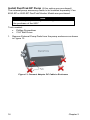
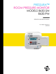
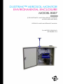
DUSTTRAK™ AEROSOL MONITOR ENVIRONMENTAL ENCLOSURE MODEL 8537 (FOR DUSTTRAK™ II AND DRX AEROSOL MONITOR MODELS 8530 AND 8533) OPERATION AND MAINTENANCE MANUAL P/N 6007870, REVISION D SEPTEMBER 2014 Copyright© TSI Incorporated / 2014 / All rights reserved. Part Number 6007870 / Revision D / September 2014 Address TSI Incorporated / 500 Cardigan Road / Shoreview, MN 55126 / USA Fax No. (651) 490-3824 LIMITATION OF WARRANTY AND LIABILITY (effective April 2014) (For country-specific terms and conditions outside of the USA, please visit www.tsi.com.) Seller warrants the goods, excluding software sold hereunder, under normal use and service as described in the operator's manual, shall be free from defects in workmanship and material for twenty-four (24) months, or if less, the length of time specified in the operator's manual, from the date of shipment to the customer. This warranty period is inclusive of any statutory warranty. This limited warranty is subject to the following exclusions and exceptions: a. b. c. d. e. f. g. h. i. Hot-wire or hot-film sensors used with research anemometers, and certain other components when indicated in specifications, are warranted for 90 days from the date of shipment; DustTrak internal pump for Models 8530 and 8533 is warranted for two (2) years or 4000 hours, whichever comes first; DustTrak external pump for Models 8530EP and 8533EP is warranted for two (2) years or 8760 hours, whichever comes first; DustTrak internal pump for Models 8530 and 8533 is warranted for operation within ambient temperatures between 5–45°C. Warranty is void when the internal pump is operating outside of this temperature range; Parts repaired or replaced as a result of repair services are warranted to be free from defects in workmanship and material, under normal use, for 90 days from the date of shipment; Seller does not provide any warranty on finished goods manufactured by others or on any fuses, batteries or other consumable materials. Only the original manufacturer's warranty applies; This warranty does not cover calibration requirements, and seller warrants only that the instrument or product is properly calibrated at the time of its manufacture. Instruments returned for calibration are not covered by this warranty; This warranty is VOID if the instrument is opened by anyone other than a factory authorized service center with the one exception where requirements set forth in the manual allow an operator to replace consumables or perform recommended cleaning; This warranty is VOID if the product has been misused, neglected, subjected to accidental or intentional damage, or is not properly installed, maintained, or cleaned according to the requirements of the manual. Unless specifically authorized in a separate writing by Seller, Seller makes no warranty with respect to, and shall have no liability in connection with, goods which are incorporated into other products or equipment, or which are modified by any person other than Seller. The foregoing is IN LIEU OF all other warranties and is subject to the LIMITATIONS stated herein. NO OTHER EXPRESS OR IMPLIED WARRANTY OF FITNESS FOR PARTICULAR PURPOSE OR MERCHANTABILITY IS MADE. WITH RESPECT TO SELLER’S BREACH OF THE IMPLIED WARRANTY AGAINST INFRINGEMENT, SAID WARRANTY IS LIMITED TO CLAIMS OF DIRECT INFRINGEMENT AND EXCLUDES CLAIMS OF CONTRIBUTORY OR INDUCED INFRINGEMENTS. BUYER’S EXCLUSIVE REMEDY SHALL BE THE RETURN OF THE PURCHASE PRICE i DISCOUNTED FOR REASONABLE WEAR AND TEAR OR AT SELLER’S OPTION REPLACEMENT OF THE GOODS WITH NON-INFRINGING GOODS. TO THE EXTENT PERMITTED BY LAW, THE EXCLUSIVE REMEDY OF THE USER OR BUYER, AND THE LIMIT OF SELLER'S LIABILITY FOR ANY AND ALL LOSSES, INJURIES, OR DAMAGES CONCERNING THE GOODS (INCLUDING CLAIMS BASED ON CONTRACT, NEGLIGENCE, TORT, STRICT LIABILITY OR OTHERWISE) SHALL BE THE RETURN OF GOODS TO SELLER AND THE REFUND OF THE PURCHASE PRICE, OR, AT THE OPTION OF SELLER, THE REPAIR OR REPLACEMENT OF THE GOODS. IN THE CASE OF SOFTWARE, SELLER WILL REPAIR OR REPLACE DEFECTIVE SOFTWARE OR IF UNABLE TO DO SO, WILL REFUND THE PURCHASE PRICE OF THE SOFTWARE. IN NO EVENT SHALL SELLER BE LIABLE FOR LOST PROFITS, BUSINESS INTERRUPTION, OR ANY SPECIAL, INDIRECT, CONSEQUENTIAL OR INCIDENTAL DAMAGES. SELLER SHALL NOT BE RESPONSIBLE FOR INSTALLATION, DISMANTLING OR REINSTALLATION COSTS OR CHARGES. No Action, regardless of form, may be brought against Seller more than 12 months after a cause of action has accrued. The goods returned under warranty to Seller's factory shall be at Buyer's risk of loss, and will be returned, if at all, at Seller's risk of loss. Buyer and all users are deemed to have accepted this LIMITATION OF WARRANTY AND LIABILITY, which contains the complete and exclusive limited warranty of Seller. This LIMITATION OF WARRANTY AND LIABILITY may not be amended, modified or its terms waived, except by writing signed by an Officer of Seller. Service Policy Knowing that inoperative or defective instruments are as detrimental to TSI as they are to our customers, our service policy is designed to give prompt attention to any problems. If any malfunction is discovered, please contact your nearest sales office or representative, or call TSI's Customer Service department at (800) 874-2811 (USA) or (001 651) 490-2811 (International) or visit www.tsi.com. Trademarks DustTrak™ and TrakPro™ are trademarks of TSI Incorporated. Netronix is a trademark of Netronix Inc. Velcro is a registered trademark of Velcro Industries B.V. ii Contents Contents............................................................................................. iii Safety Information ............................................................................. v Laser Safety ............................................................................................ vi Labels ..................................................................................................... vii Description of Caution/Warning Symbols ............................................... vii Caution and Warning Symbols .............................................................. viii Reusing and Recycling .......................................................................... viii Chapter 1 Parts Identification and Unpacking ............................... 1 Parts Identification: Environmental Enclosure ......................................... 1 Unpacking the Model 8537 DustTrak Aerosol Monitor Environmental Enclosure ..................................................................... 3 Model 8537 DustTrak Aerosol Monitor Environmental Enclosure Optional Accessories ........................................................................... 5 Chapter 2 Setting Up ........................................................................ 9 Install the Padlock Adapter ...................................................................... 9 Install the Door Vents and Screens ....................................................... 10 Installation of the Box Handles .............................................................. 11 Install the Aerosol Inlet .......................................................................... 12 Install Water Trap Bottle ........................................................................ 13 Install DustTrak Monitor Shelf................................................................ 14 Install DustTrak EP Pump (if this option was purchased) ...................... 16 Install Enclosure Battery Bracket and Mount Batteries (optional accessory) ......................................................................................... 19 Install DustTrak Monitor in the Environmental Enclosure ...................... 22 Install Sample Inlet Tubing .................................................................... 23 Install Impactor in the Sample Flow (optional accessory) ...................... 24 Install Pole Mount Accessory (optional accessory)................................ 25 Install External Weatherproof AC Adapter (optional accessory) ............ 27 Install GSM/GPS Communication Modem (optional accessory) ............ 28 Install Solar Heat Shield (optional accessory) ....................................... 28 Install Heated Inlet (optional accessory) ................................................ 28 Setting-up the Solar Cell Power System (optional accessory) ............... 29 Chapter 3 Supplying Power ........................................................... 39 Using the External Weatherproof AC Adapter ....................................... 39 Using the Internal Battery Pack (optional accessory) ............................ 39 Using the Solar Cell Power System (optional accessory) ...................... 40 Chapter 4 Operation ....................................................................... 41 Overview ............................................................................................... 41 How to Properly Orient the Environmental Enclosure ............................ 41 Changing and Re-charging the Battery Packs ....................................... 42 Zeroing the DustTrak II/DRX Aerosol Monitor ........................................ 46 Checklist for Sampling with the Environmental Enclosure ..................... 46 Communication and Data Acquisition .................................................... 47 Transporting the Environmental Enclosure ............................................ 47 iii Chapter 5 Maintenance ................................................................... 49 Daily Maintenance Checks ..................................................................... 49 Cleaning the Aerosol Inlet ...................................................................... 49 When to Change the Battery .................................................................. 49 Replacing the Battery Pack .................................................................... 50 Recharging the Battery Packs ................................................................ 50 Battery Pack Life .................................................................................... 52 Emptying the Water Trap ....................................................................... 54 Storage Precautions ............................................................................... 54 Chapter 6 Troubleshooting the Environmental Enclosure ......... 55 Appendix A Specifications ............................................................. 57 Environment Enclosure .......................................................................... 57 Solar Power System ............................................................................... 58 iv Safety Information WARNING The DustTrak™ II/DRX aerosol monitor is not rated for intrinsic safety. The DustTrak monitor, with the Environmental Enclosure, must never be operated under conditions where there is a risk of fire or explosion. WARNING Use of components other than those specified by TSI may impair the safety features provided by the equipment. WARNING The instrument has been design to be used with batteries supplied by TSI. Do not use a substitute. The TSI charger (P/N 801809) has been designed to be used with the battery packs supplied by TSI. Do not use a substitute charger to charge TSI battery packs. Old batteries must be properly recycled in accordance with the local environmental regulations. WARNING Do not use non-rechargeable batteries in this instrument. Fire, explosions, or other hazards may result. Caution The enclosure is designed to be water resistant to rain or spray. It has a NEMA rating of 3R. It is not designed to be waterproof when immersed. Setting it in a pool of water will result in flooding the inner compartment with water. This will severely damage both your DustTrak II/DRX aerosol monitor and battery pack. Do NOT set the Environmental Enclosure in water! v Note Prior to using the Battery Pack for the first time, a full recharge is recommended. Recharging Battery Pack(s) immediately after use (within one hour maximum) is critical to obtaining optimal recharge time, battery health, and battery life. Laser Safety The Model 8530/8533 DustTrak monitor is a Class I laser- based instrument During normal operation, you will not be exposed to laser radiation Precaution should be taken to avoid exposure to hazardous radiation in the form of intense, focused, visible light Exposure to this light may cause blindness Take these precautions: DO NOT remove any parts from the DustTrak monitor unless you are specifically told to do so in this manual. DO NOT remove the housing or covers. There are no serviceable components inside the housing. WARNING The use of controls, adjustments, or procedures other than those specified in this manual may result in exposure to hazardous optical radiation. WARNING There are no user-serviceable parts inside this instrument. The instrument should only be opened by TSI or a TSI approved service technician. W A R N I N G If the DustTrak monitor is used in a manner not specified by the manufacturer, the protection provided by the equipment may be impaired. vi When operated according to the manufacturer’s instruction, this device is a Class I laser product as defined by U.S. Department of Health and Human Services standards under the Radiation Control for Health and Safety Act of 1968. A certification and identification label like the one shown below is affixed to each instrument. Labels Advisory labels and identification labels are attached to the instrument. 1. Battery label or 2. European symbol for non-disposable item. Item must be recycled. Description of Caution/Warning Symbols Appropriate caution/warning statements are used throughout the manual and on the instrument that require you to take cautionary measures when working with the instrument. Caution Caution Failure to follow the procedures prescribed in this manual might result in irreparable equipment damage. Important information about the operation and maintenance of this instrument is included in this manual. Warning WARNING Warning means that unsafe use of the instrument could result in serious injury to you or cause damage to the instrument. Follow the procedures prescribed. vii Caution and Warning Symbols The following symbols may accompany cautions and warnings to indicate the nature and consequences of hazards: Warns that the instrument contains a laser and that important information about its safe operation and maintenance is included in the manual. Warns that the instrument is susceptible to electrostatic discharge (ESD) and ESD protection should be followed to avoid damage. Indicates the connector is connected to earth ground and cabinet ground. Reusing and Recycling As part of TSI Incorporated’s effort to have a minimal negative impact on the communities in which its products are manufactured and used: Do not dispose of used batteries in the trash. Follow local environmental requirements for battery recycling. If instrument becomes obsolete, return to TSI for disassembly and recycling. viii Chapter 1 Parts Identification and Unpacking Carefully unpack the Model 8537 DustTrak™ Aerosol Monitor Environmental Enclosure from the shipping container. Use the tables and illustrations below to make certain that there are no missing components. Contact TSI immediately if anything is missing or damaged. Parts Identification: Environmental Enclosure Identify the parts of the Model 8537 DustTrak Aerosol Monitor Environmental Enclosure (Figure 1 and Figure 2). Please become familiar with these components before proceeding. Inlet Fitting with Water Trap* Power Connectors DustTrak Monitor Shelf* Battery Bracket* *Denotes components need to be installed Figure 1: Inside View of Environmental Enclosure 1 Inlet Assembly* Antenna Location** Pad Lock* *Denotes components need to be installed **Denotes a purchased accessory USB Pass Through Connection DC Power Connection Figure 2: Outside Views of Environmental Enclosure 2 Chapter 1 Unpacking the Model 8537 DustTrak Aerosol Monitor Environmental Enclosure Compare all the components you received with those listed in the table below. If any parts are missing, contact TSI. Item Qty Part Number Description 1 801567 Environmental Enclosure OmniDirect Inlet with Extended Rain Cap 1 Refer to 801831 accessory kit. Sample Inlet Tubing 1 Refer to 801831 accessory kit. Inlet Fitting for Sample Tubing 1 Refer to 801831 accessory kit. Water Trap Bottle 1 Refer to 801831 accessory kit. Velcro® Straps 1 801832 8537 Internal DustTrak monitor DC Power Cable Parts Identification and Unpacking 3 Item 4 Qty Part Number Description 1 Refer to 801833 Spare Netronix connection kit. Netronix™ Node Power Cable 1 Refer to 801833 Spare Netronix connection kit. Right Angle USB Cable 2 Handle 1 DustTrak Monitor Shelf 1 Battery Bracket and Cable 2 Door Vents 1 Door Padlock Chapter 1 Item Qty Part Number Description External Pump mounting kit. (90 degree fitting, pump mounting screws 4x) Used if installing an 8530-EP or 8533-EP external pump DustTrak monitor. 1 1 801854 12 VDC Weatherproof Universal Power Adapter (100 to 250 VAC) 1 6007870 Model 8537 DustTrak Aerosol Monitor Environmental Enclosure Operation and Maintenance Manual Model 8537 DustTrak Aerosol Monitor Environmental Enclosure Optional Accessories Listed below are optional accessory items for the Model 8537 DustTrak Aerosol Monitor Environmental Enclosure. Contact TSI for purchase info. Item Part Number Description 801808 12 VDC Battery Pack* *Battery will require 801845 mounting kit if mounting kit has not been previously purchased Parts Identification and Unpacking 5 Item Part Number Description 801809 12 VDC Battery Pack Charger 801807 Internal Battery System (Two 22Ah Batteries and charger)* *Each Battery place in the enclosure will require 801845 mounting kit if mounting kit has not been previously purchased 6 801845 8537 Battery mounting kit 801811 Solar Cell Power System 801844 Pole Mount Kit 801900 GSM/GPS Communication Modem 801846 8537 Heat Shield Assembly Chapter 1 Item Part Number Description 801850/ 801851 Heated Inlet Accessory 801850 with Auto Zero 801851 without Auto Zero 801831 Parts Identification and Unpacking 8537 Environmental Enclosure Spare Parts (contains: water bottle, Velcro® strap, conductive tubing, connection fitting, O-rings) 7 (This page intentionally left blank) 8 Chapter 1 Chapter 2 Setting Up The setup of the Environmental Enclosure is an important part in allowing reliable and accurate sampling of aerosols in a wide range of conditions. TSI cannot ensure accurate measurements if any of the components are set up incorrectly. Failure to follow these procedures could result in damage to the enclosure or its components. Install the Padlock Adapter The Padlock adapter allows for the case to be locked. The following steps describe how to install the Padlock Adapter. Tools needed: 1/8” Ball Driver 3/8” Wrench 1. Place the Padlock adapter on the front door and push the mounting screws through the pre-drilled holes as shown in Figure 3. Figure 3: Mounting of the Padlock Adapter 9 2. Secure the Padlock adapter to the door using washers and screws as shown in Figure 4. Figure 4: Securing of the Padlock Adapter Install the Door Vents and Screens Install the Vents and Screens to the front door. 1. Push the vent through the front door as shown in Figure 5 (2 places). Figure 5: Place Vent Cover through Front Door 10 Chapter 2 2. Attach filter screen to vent cover by twisting on thread using hand. Figure 6: Attach Filter Screen to Vent Cover Installation of the Box Handles Install the handles to the sides of the enclosure. Tools needed: 9/16” Wrench 1. Push the handle mounting threads through the holes located at the top side of the box and attach using the enclosed 3/8” Nut and 3/8” washers as shown in Figure 7 (2 places). Figure 7: Attach Handles to the Side of the Enclosure Setting Up 11 Install the Aerosol Inlet The inlet assembly allows ambient aerosols to be sampled efficiently in a wide range of conditions. Proper installation into its sampling position ensures that the DustTrak II/DRX aerosol monitor measures an accurate ambient aerosol mass concentration. Follow these instructions to install either of the aerosol inlets: 1. Remove the Inlet Transport Plug from bubble pack. Caution Always hold the inlet assembly by the knurled portion of the tube. Do not twist on the inlet assembly cap. 2. Thread the inlet assembly into upper inlet ring found on the top of the Environmental Enclosure (see Figure 8). Figure 8: Thread the Inlet into the Inlet Ring Notes Make sure that a thin film of vacuum grease is coating both O-rings on the inlet tube to ensure a good seal before installing it. 12 Chapter 2 Install Water Trap Bottle The translucent bottle that attaches to the bottom of the inner inlet is used to collect any water that is drawn into the sampled flow. This prevents water from reaching the DustTrak II/DRX aerosol monitor and damaging it. The bottle is not installed on the Environmental Enclosure when it is shipped. If the bottle is removed for cleaning, follow these precautions when re-installing: 1. Before screwing the bottle into inner inlet ring, be sure that the O-ring found in the bottom of the threaded hole is greased. This ensures an air-tight seal. 2. When threading the bottle into the inlet, be careful not to damage its threads. 3. Make sure the bottle has been securely tightened, and that it is in the correct orientation as shown in Figure 9. Figure 9: Install the Water Trap Bottle Setting Up 13 Install DustTrak Monitor Shelf Attach the shelf to hold the DustTrak monitor to the back plane of the enclosure. Tools needed: 7/64” Ball Driver 1/8” Ball Driver 1. A Velcro® strap is provided to secure the DustTrak monitor to the Enclosure. Make sure the Velcro® straps are present in the Enclosure bracket as shown in Figure 10. Figure 10: DustTrak Aerosol Monitor Velcro® Straps 14 Chapter 2 2. Install the DustTrak monitor power cable and strain relief shown in Figure 11. Figure 11: Install DustTrak Power Cable and Strain Relief 3. Place the shelf against the backplane of the enclosure and align with threaded holes as shown in Figure 12. Figure 12: Install the DustTrak Shelf Notes The backplane has treaded inserts to attach the shelf, so nuts do not need to be used to attach the shelf. 4. Securely fasten all four #10 screws and washers. Setting Up 15 Install DustTrak EP Pump (if this option was purchased) The external pump accessory needs to be installed separately if an 8530-EP or 8533-EP DustTrak Monitor Model was purchased. Note An external pump mounting kit was shipped standard with the purchase of the 8537. Tools needed: Phillips Screwdriver 7/64” Ball Driver 1. Remove External Pump Pads from the pump enclosure as shown in Figure 13. Figure 13: Connect Adapter DC Cable to Enclosure 16 Chapter 2 2. Open enclosure and insert mounting screws in the mounting holes as shown in Figure 14. Figure 14: Place Mounting Screws 3. Mount external pump to the back plan using mounting screws and replace the cover as shown in Figure 15. Figure 15: Mount External Pump Setting Up 17 4. Modify exhaust port by removing quick connect fitting and installing 90 degree fitting as shown in Figure 16. Figure 16: Exhaust Port Modification 5. Remove the black tube from one of the quick disconnect fittings and slide tube over the barb of the 90° Fitting. Attach Air line from exhaust port of the DustTrak monitor to the inlet port of the external pump and attach external pump control cable to the DustTrak monitor as shown in Figure 17. Review 8530/33-EP manual for details on the air and control cable connection. Figure 17: Connect External Pump to DustTrak Monitor 18 Chapter 2 Install Enclosure Battery Bracket and Mount Batteries (optional accessory) The DustTrak monitor and other internal accessories can be powered off the optional battery accessory. To use the optional battery accessory, battery brackets and cabling will need to be installed into the case followed by the placement of the batteries. The installation steps are shown below for the battery bracket. Note To integrate the battery into the environmental enclosure, the battery will need to be purchased as an optional accessory. One of the battery accessories needs to be purchased (PN 801808 or PN 801807, see accessory table at the front of this manual for details). Tools needed: 7/64” Ball Driver Phillips Screwdriver 1. Attach the battery power cable to the battery bracket using provided screws and zip ties, as shown in Figure 18. Tray Harness #4 Screw Zip Tie Figure 18: Battery Cable Placement Setting Up 19 2. Attach the bracket to the bottom of the DustTrak Monitor Shelf. If one battery is used, attach the bracket to the left side. If two batteries will be used, attach a second bracket to the right side. The second bracket does not need a battery power cable. See Figure 19. Figure 19: Battery Bracket Attachment 3. Attach the battery cable back contact to the backplane connector as shown in Figure 20. Figure 20: Attach Battery Cable to Backplane 20 Chapter 2 4. Place batteries in case and attach battery leads to the battery cable. If using one battery, place on left side. If using two batteries, place on both sides as shown in Figure 21. Note A single battery bracket and wiring comes standard with the purchase of an 8537 Environmental Enclosure. If using two batteries, a second battery bracket (PN 801845) needs to be purchased. Figure 21: Placement and Connection of the Batteries Setting Up 21 Install DustTrak Monitor in the Environmental Enclosure The internal shelf of the Environmental Enclosure is designed to hold the DustTrak monitor securely in place, using the provided Velcro® straps. 1. Install the DustTrak monitor into the shelf as shown in Figure 22 and tightly secure in place with the Velcro® straps. Attach the Power and USB cables as shown (USB cable used for GSM/GPS communication modem accessory). Figure 22: Install DustTrak Monitor in the Bracket 22 Chapter 2 Install Sample Inlet Tubing The Sample Inlet Tubing directs the sample aerosol flow from the Sample Inlet to the DustTrak monitor. 1. Make sure that the Inlet Fitting is inserted into the Inner Inlet Ring as shown in Figure 23. 2. Attach the Sample Inlet Tubing to the Inlet Fitting. 3. The other end of the Sample Inlet Tubing connects directly to the DustTrak monitor. Figure 23: Install the Barbed Inlet Fitting and Sample Inlet Tubing Setting Up 23 Install Impactor in the Sample Flow (optional accessory) Optional Impactors are available as accessories to the DustTrak II aerosol monitor. These Impactors can be placed in the Sample Flow in the Environmental Enclosure system as detailed below. Note Refer to the DustTrak II Aerosol Monitor manual for Impactor usage and maintenance information. 1. Remove the Inlet Fitting from the water bottle mount. 2. Insert the Impactor in the water bottle mount in its place. 3. Then insert the Inlet Fitting in the other end of the Impactor as shown in Figure 24. Figure 24: Install Impactor in the Sample Flow 24 Chapter 2 Install Pole Mount Accessory (optional accessory) The Pole Mount Accessory is used to mount the 8537 to a pole. This accessory will need to be assembled and installed on to the 8537 enclosure. Tools Needed: 5/32” Ball Driver 7/16” Wrench 9/16” Deep Well Socket with extension 9/16” Wrench 1. Attach the pole mount bracket to the cross bars using provided ¼” screws, washers and locknuts as shown in Figure 25. Figure 25: Pole Mount Assembly Setting Up 25 2. Attach the pole mount accessory to 4 locations on the environmental enclosure using the provided 3/8” screws, washers and nuts as shown in Figure 26. Figure 26: Attach Pole Mount Accessory to Enclosure 3. The enclosure can now be attached to a pole using mounting straps that are looped through the slots in the pole mount bracket. 26 Chapter 2 Install External Weatherproof AC Adapter (optional accessory) Use the external weatherproof AC/DC adapter when dedicated AC power is available for powering the instrument. 1. The external power adapter can be mounted to the pole mount accessory as shown in Figure 27, or mounted elsewhere on the case using its mounting holes. The DC cable connects to the DC power connector on the left side of the enclosure. Note If attaching the AC adapter directly to the environmental enclosure, the user drilled holes need to be sealed to maintain the NEMA 3R rating. Figure 27: Attaching AC/DC Power Adapter Setting Up 27 2. Ensure the internal cable from the DC power connector is attached to the enclosure backplane as shown in Figure 28. Figure 28: Internal Power Cable Install GSM/GPS Communication Modem (optional accessory) Installation documentation found in the quick start document shipped with each optional accessory (P/N 6007911). Contains FCC ID: RI7HE910 Contains IC: 5131A-HE910 The GSM/GPS accessory complies with Part 15 of the FCC Rules. Operation is subject to the following conditions. This device may not cause harmful interference and this device must accept any interference received, including interference that may cause undesired operation. The antennas used for this transmitter must be installed to provide a separation distance of at least 20 cm from all persons. Use only the supplied antenna. Install Solar Heat Shield (optional accessory) Installation documentation found in the quick start document shipped with each optional accessory (P/N 6007913). Install Heated Inlet (optional accessory) Installation documentation found in the quick start document shipped with each optional accessory (P/N 6007667). 28 Chapter 2 Setting-up the Solar Cell Power System (optional accessory) The full Solar Cell Power System is shown in Figure 29. The following section details the setup of this system. Important Make all Solar Cell Power System electrical connections in the order outlined below. Damage to the system can occur if connections are not made in this order. Figure 29: Solar Cell Power System 1. Remove the Solar Battery from its packaging and place it in the Solar Battery Enclosure box. Make sure that the battery positive (+) terminal is on the left (the positive terminal is noted on the battery with a RED marking). Remove the battery terminals using an adjustable wrench and connect the ring terminal ended wires from the solar charge controller to the battery terminals (see Figure 30). Note There are two wires coming from the charge controller: one is BLACK and is labeled (+); the other is WHITE and is labeled (–). The BLACK (+) wire should be connected to the battery positive (+) terminal, which has a red marking on the top of the battery. The WHITE (–) wire should be connected to the battery negative (–) terminal. Setting Up 29 Figure 30: Install the Solar Battery and Connect to Controller 2. The next step is to attach the provided power cables with waterproof connectors to each Solar Cell. Remove the Solar Cell from its packaging and access the junction box on the end of the panel. Remove the screws and sealing strip from inside the box and set aside. Remove the center of one of the access holes which is labeled ½”. Pass the power cable through that access hole while attaching the individual pieces of the cable strain relief, as shown in Figure 31. Figure 31: Strain Relief and Power Cable through Access Hole 30 Chapter 2 3. Next, attach the power cable to the Solar Cell screw terminals as shown in Figure 32 and Figure 33. Note Make sure the wires are connected as shown below. Connecting the wires incorrectly can cause severe damage to the Solar Power System. Refer to the Solar Cell manufacturer’s specification sheet for additional details. BLACK power cable wire connected to RED Solar Term. This is the POSITIVE (+) connection. WHITE power cable wire connected to GREY Solar Term. This is the NEGATIVE (-) connection. Negative (-) Negative (-) Setting Up Positive (+)) Positive (+)) Figure 32: Power Cable Connection to Solar Cell Terminals (Supplier part number 485J and 490J. See solar panel instructions for details.) Figure 33: Power Cable Connection to Solar Cell Terminals. (Supplier part number 90J. See solar panel instructions for details). 31 4. With the wires tightened, secure the terminal block in its retaining clips, and tighten the strain relief connections to the power cable as shown in Figure 34. Figure 34: Secure Terminal Block and Tighten Strain Relief 32 Chapter 2 5. Next, attach the sealing strip to the inside of the junction box cover, as shown in Figure 35. Figure 35: Apply Sealing Strip to Junction Box Cover Setting Up 33 6. Then attach the cover to the junction box using the supplied screws, as shown in Figure 36. Figure 36: Attach Junction Box Cover 7. Now attach the two Solar Cells to the adjustable angle Mounting Frame using the supplied bolts, as shown in Figure 37. Figure 37: Assemble the Solar Cells on the Mounting Frame 34 Chapter 2 8. The support bar may also be attached to each side of the Mounting Frame, as shown in Figure 38. Figure 38: Assemble the Support Bar to the Mounting Frame For best results, mount the Solar Cells at an angle directly pointed at the path of the sun, allowing the maximum power to be collected by the Solar Cells. To secure the Mounting Frame to the ground, use the bolt locations at the end of each frame arm, or add sandbags or other weights to the support bar. Setting Up 35 9. Connect the Solar Cell cables to the Solar Battery Enclosure box as shown in Figure 39. The Green LED on the Solar Charge Controller will illuminate when sunlight power is available, and the Solar Battery is charging. Note Do not connect the Solar Cells directly to the 8537 Environmental Enclosure as this may result in damage to the DustTrak Aerosol Monitor. The Solar Cells must be connected to the Solar Battery Enclosure Box so they can be regulated by the Solar Charge Controller. Prior to using the Solar Cell Power System for the first time, a full recharge of the Solar Battery is recommended. Simply allow the Solar Battery to charge for a day with sunlight power from the connected Solar Cells. Figure 39: Connect Solar Cells to Battery Enclosure Box 36 Chapter 2 10. Now connect the Solar Battery Enclosure to the 8537 Environmental Enclosure using the provided outdoor DC power cable with weatherproof connectors, as shown in Figure 40. DC power is now available at the Environmental Enclosure, and the internal DC power split cable is used to power the DustTrak monitor and the optional Radio Modem. Note The Solar Charge Controller has built-in low voltage cutout protection for the Solar Battery. If extended non-sunlight conditions occur, causing the Solar Battery to become deeply discharged, the Solar Charge Controller temporarily cuts off output power. The Red LED on the Solar Charge Controller will illuminate when this condition occurs. Once sunlight returns, and the Solar Battery has been recharged to an appropriate level, the Red LED will turn off and the Solar Charge Controller will re-enable the power output. Figure 40: Connect Power from the Solar Cell Power System to the Environmental Enclosure Setting Up 37 (This page intentionally left blank) 38 Chapter 2 Chapter 3 Supplying Power The DustTrak II/DRX Aerosol Monitor may be powered in one of three ways when used with the Model 8537 Environmental Enclosure: 1. Use external weatherproof AC adapter, when AC power is desired. 2. Use the optional Battery Pack(s) (Single or Dual). 3. Use the optional Solar Cell Power System. Using the External Weatherproof AC Adapter Make sure that the external weatherproof AC adapter is securely mounted to the outside of the Enclosure and that its DC output cable is connected to the DC input connector on the outside of the Enclosure (as described earlier in this manual). After the adapter is plugged into an AC voltage source, DC voltage is then available on the inside of the case at the 3-pin connector interface that is routed to the power distribution backplane. Notes A 12 VDC output weatherproof AC/DC adapter rated for 90 to 240 VAC input is provided with the 8537 Environmental Enclosure System Universal input AC plug adapters are included with the 8537 Environmental Enclosure for changing to a different AC plug style. Using the Internal Battery Pack (optional accessory) The battery packs supplied with the Environmental Enclosure allow for extended use of the DustTrak monitor. The battery pack enables the DustTrak monitor to operate for at least 34 hours (even in cold conditions). If an External Pump is used with the DustTrak monitor, then operation will last at least 23 hours. If longer operation time is desired, the Dual Battery Wiring Harness is available to increase operation time by roughly twice the numbers quoted above for a single battery pack. To ensure a minimal battery recharge time and a prolonged lifetime, rotate and properly charge the battery packs immediately after each use (see Maintenance section for further information). Make sure that fully-charged internal batteries are installed correctly within the DustTrak monitor to make it possible to continue sampling when swapping-out one external Battery Pack with a charged Battery Pack. 39 Connect the one end of the DC power split cable to the battery pack output, and the other end to the DustTrak monitor. If using the optional Dual Battery Wiring Harness, simply connect each battery pack output to either male plug connector available, then connect the female connector to one end of the DC power split cable. Now, connect the other end of the DC power split cable to the DustTrak monitor. The additional connection is used to power the optional RF Radio Modem used with the Model 8535 enclosure. A different power connector will be provided with the GSM/GPS Wireless Communication Modem. Note Prior to using the Battery Pack for the first time, a full recharge is recommended. Recharging Battery Pack(s) immediately after use (within one hour maximum) is critical to obtaining optimal recharge time, battery health, and battery life. Note Use of components other than those specified by TSI may impair the safety features provided by the equipment. Using the Solar Cell Power System (optional accessory) The DC power output of the Solar Cell Power System connects to the DC input connector on the right side of the Enclosure. Internal power connections are made on the inside of the Enclosure at the 3-pin connector interface that is routed to the power distribution backplane. See “Setting-up Solar Cell Power System” section of this document for additional details on the Solar Cell Power System setup. Note Prior to using the Solar Cell Power System for the first time, a full recharge of the Solar Battery is recommended. 40 Chapter 3 Chapter 4 Operation Overview The DustTrak™ Environmental Enclosure can be used in conjunction with the DustTrak II and DustTrak DRX aerosol monitor for many different applications. Its primary use is in outdoor applications to give the DustTrak monitor protection from the elements and the ability to sample efficiently in different wind speeds. The enclosure and extended-life battery may also be advantageous in indoor industrial applications, to provide additional security and protection to the DustTrak monitor. How to Properly Orient the Environmental Enclosure Set up the Environmental Enclosure in a location where it can sample the particles of interest. It should be placed “out in the open,” away from obstructions which may affect wind currents. For example, do not place it at the corner of a building, which would cause swirling wind currents and result in poor particle sampling. Use the Environmental Enclosure in wind conditions with speeds of 22 mph or less to obtain the most accurate readings. An increase in wind speed over 22 mph can decrease the sampling efficiency of the inlet to under the efficiency specified by PM-10 standards. If wind gusts of over 22 mph are present, the data collected is still valid, but be aware that the readings will be slightly lower than the actual mass concentration of aerosol present. If the Environmental Enclosure is exposed to direct sunlight, causing the temperature inside to approach the operating limit of 50°C, the Heat Shield Assembly should be used. The Heat Shield Assembly blocks the direct sunlight, keeping the temperature inside the Environmental Enclosure cooler than it would otherwise be. Orient the Environmental Enclosure with Heat Shield Assembly such that the Heat Shield faces the sun directly when the sun is at its highest point in the sky. This will maximize the effectiveness of the Heat Shield. 41 Changing and Re-charging the Battery Packs If using a DustTrak monitor, change the battery packs within the Environmental Enclosure at least every 34 hours of use. However, if using a DustTrak monitor with External Pump, change the battery packs within the Environmental Enclosure every 23 hours of use. If using the Heated Inlet with the DustTrak monitor with External Pump, change the battery within 15 hours. TSI recommends replacing the battery pack(s) during the daily maintenance check described in the Maintenance section. A voltage cutoff switch will cut the power to the DustTrak II/DRX aerosol monitor when the battery voltage reaches 10.5 V. This ensures that the battery does not become too deeply discharged to recover, and also prevents the DustTrak monitor from operating below its rated voltage input. Preventing this condition will prolong the life of the battery. If storage is required, battery packs should be fully charged prior to storage to prolong the life of the battery and be left off of charge for no longer than 3 months maximum. However, it is NOT recommended to store battery packs off of charge. Battery packs stored off charge may result in shorter than average life. Battery packs will age over time per usage and care. The battery packs will last 180 to 200 cycles on average. One cycle being defined as one battery pack discharge and one recharge process. With optimal use and care, the life of a battery pack may possibly increase beyond 200 cycles. For optimal battery health, keep battery packs on charge in a cool, dry, and well-ventilated area while NOT in use, and recharge battery packs immediately after use. If battery packs are stored off of charge for durations longer than 30 days then longer charge times and shorter run-times may result due to degraded battery health. Battery pack health will diminish at a much more rapid pace if NOT recharged immediately (within one hour maximum) after use. It is important to remove a battery pack from service if signs of diminished run-time or longer charge time are observed. These are signs of battery pack aging and poor general battery health. To identify unhealthy battery packs, it is important to review and adhere to the maintenance recommendations listed within Chapter 5. A battery pack in good health will take near 8 to 9 hours to fully charge. A battery pack that provides 30% less product run-time than expected is ready to be removed from service. If a given battery pack provides a run-time of 24 hours or less for the DustTrak monitor 42 Chapter 4 or a run-time of 17 hours or less for the DustTrak monitor with External Pump, or a run-time of 10 hours or less for the DustTrak monitor with External Pump and Heated Inlet, the battery pack should be removed from service and properly recycled in accordance with local environmental regulations. Note Prior to using the Battery Pack for the first time, a full recharge is recommended. Recharging Battery Pack(s) immediately after use (within one hour maximum) is critical to obtaining optimal recharge time, battery health, and battery life. WARNING The instrument has been designed to be used with batteries supplied by TSI. Do not use a substitute. The TSI charger (P/N 801809) has been designed to be used with the battery packs supplied by TSI. Do not use a substitute charger to charge TSI battery packs. Old batteries must be properly recycled in accordance with the local environmental regulations. W A R N I N G Do not use non-rechargeable batteries in this instrument. Fire, explosions, or other hazards may result. Charging Battery Pack 1. Disconnect the battery pack from the DustTrak II/DRX aerosol monitor and remove it from the Environmental Enclosure. Take it to a protected area where it can be charged undisturbed for 8 to 9 hours. Before charging any battery pack, please completely read the “Battery Charger Owner’s Manual” that was provided along with your charger. Do NOT attempt to charge Battery Packs using the Dual Battery Wiring Harness (P/N 801817). The Dual Battery Wiring Harness is designed to be used to power the 8530, 8531, 8533, 8530EP, or 8533EP and the wireless radio modem during instrument operation only. The information below is NOT intended as a substitute to the charger manual. The charger manual will cover all important Operation 43 warnings and operating instructions for using the charger. The steps below will guide you through the battery pack charging process steps. 2. Select the manual switch setting on the back of the charger to the setting that matches the correct power distribution present in your local area (i.e., 115 VAC or 240 VAC). 3. Connect the charger to the battery pack by connecting the battery pack output connector to the mating charger connector. 4. Plug the battery charger’s power AC plug (Red colored) into an AC outlet. The “ON” LED will light red momentarily then the “ON” LED will turn off and the “CHARGE” LED will light solid yellow. This indicates that the charging process has started. 5. The “CHARGE” LED will remain lit solid yellow until the battery pack is charged to a state of charge of 80% then the “CHARGE” LED will start to flash yellow for the remainder of the charging process until the battery pack reaches a fully charged state. The duration of time the charger will remain in charging mode depends upon state of discharge of the battery. It is important to allow the charger to go through a complete charging routine in order to charge each battery pack to an optimum level. Even if a battery pack is already charged, the charging process will take a minimum of one hour. Note Do NOT stop charging a battery before it is completely charged. Battery packs should be completely charged before using. Once the battery pack is completely charged, the yellow “CHARGE” LED light will turn off and then the “READY” LED will light green to indicate that the battery pack is ready for use. The battery is fully charged at this point. The charger can remain connected in this state indefinitely—it will continue to float charge the battery at a very low level with no risk of overcharging the battery. Leaving the battery pack connected to the charger while not in use is highly recommended, and doing so will maintain the battery at a fully charged state and support optimum battery pack health while it is not in use. 6. ALWAYS DISCONNECT THE CHARGER FROM THE AC POWER SUPPLY (REMOVE AC PLUG FROM WALL SOCKET) BEFORE REMOVING THE BATTERY PACK FROM THE CHARGER AFTER CHARGING HAS COMPLETED. This will 44 Chapter 4 prevent the possibility of arcing during the battery disconnect process. 7. The charger is equipped with a time-out feature. The time-out feature is designed to prevent over-charging aging battery packs or battery packs having poor health due to abuse. The time-out feature may also protect against charger faults. The time-out feature does NOT trigger during normal operation of charging healthy battery packs. This feature is triggered if a battery pack does not reach the correct state of charge within a defined time period. When the time-out feature is triggered, the charger will simply shut-down charging the battery and is indicated by a continuous flashing of the green “READY” LED. In the event that the time out feature is triggered, remove the battery pack from service immediately and recycle the battery pack appropriately. When a time-out event occurs, the charger must be reset before being used again. To reset the charger simply disconnect the battery from the charger, or disconnect the AC plug from the charger momentarily then reconnect the charger to AC power. If the time-out feature should trigger multiple times on different battery packs, contact TSI Incorporated for assistance. Using the Dual Battery Wiring Harness The Dual Battery Wiring Harness (P/N 801817) is a product option used to connect two battery packs together to provide roughly twice the run-time provided with a single battery pack. You can expect at least 42 hours run-time if powering a TSI P/N 8530EP/8533EP, and 68 hours run-time if powering a TSI P/N 8530/8531/8533. To use the Dual Battery Wiring Harness, simply connect two battery packs to the Dual Battery Wiring Harness at the male connectors and then connect the female connector to the Internal DC Power Cable connector. Once the cable is connected, power will be delivered to the DustTrak Aerosol Monitor and optional radio modem in manner which supports even power distribution. The Dual Battery Wiring Harness is NOT intended for use to charge battery packs. The cable is designed specifically to prevent the use of the cable to charge battery packs through the cable interface. Be careful to NOT put unnecessary strain on the cable or connectors. Only connect the Dual Battery Wiring Harness after installing battery packs into the environmental enclosure case. Moreover, be sure to disconnect the Dual Battery Wiring Harness prior to removing battery packs from the environmental enclosure case. Only use the cable internal to the environmental enclosure case. Operation 45 The Dual Battery Wiring Harness is water-resistant, but NOT waterproof, the cable may fail if subjected to abundant water exposure including submersion in water. Zeroing the DustTrak II/DRX Aerosol Monitor Always zero the DustTrak II and DustTrak DRX monitor before beginning a sample. See the instructions in the DustTrak II or DustTrak DRX user manual for more information. If possible, zero the instrument under stable ambient temperature conditions (since variations in temperature will have a small impact upon the DustTrak monitor readings). If this is not possible (for example, 24-hour outdoor sampling, with wide temperature swings) the instrument should be kept closed inside the Environmental Enclosure. The thermal mass of the Enclosure will dampen out the effect of temperature swings, radiant heat, etc. In nearly all cases, the temperature impact upon the DustTrak II/DRX aerosol monitor reading is very small in comparison to the ambient particle concentration. Checklist for Sampling with the Environmental Enclosure Before beginning a sample, check to see that all of the following conditions are satisfied: All components are properly installed into the enclosure as described in the Setup section. The DustTrak II/DRX monitor has been zeroed at the temperature at which it will be sampling (if possible). The Environmental Enclosure has been put in a place clear of any obstructions that will affect the flow around the enclosure. The Enclosure is not resting directly on the ground (no standing water). The DustTrak II/DRX monitor has been set to the appropriate logging mode. The Enclosure is locked shut to prevent theft or vandalism to instrument. Plans have been made to check for maintenance and data collection every 24 hours after initial set up, if necessary. After the completion of monitoring, follow the procedures for transporting the Environmental Enclosure in the Setting Up section of this manual. This prevents the instrument from becoming damaged. 46 Chapter 4 Communication and Data Acquisition The DustTrak monitor records data in either the manual sampling mode or the programmable modes. See the DustTrak II or DustTrak DRX user manual for more information on setting up the logging modes. To download the data, attach the supplied USB cable from the USB pass-through connector to a computer USB port, and use the appropriate commands within the TrakPro software. Note In order to download a data file, the DustTrak II monitor cannot be in a sampling mode. To download a file under normal data-logging operations, do the following: 1. Open the Environmental Enclosure. 2. Discontinue sampling. 3. Attach the USB cable from the DustTrak monitor to a notebook computer. 4. Download the data file using TrakPro™ software. Transporting the Environmental Enclosure When transporting the Environmental Enclosure it is important to store its components correctly. To ensure that no damage is done to the enclosure or its components during transportation, the following steps should be taken: Attention The Environmental Enclosure is designed to protect equipment during stationary sampling only. Do not transport or ship equipment inside the Environmental Enclosure. 1. Unscrew the aerosol inlet from the top of the case. 2. Empty any water from the water trap. 3. Remove antenna and extender for GSM/GPS modem accessory if in use. 4. Remove temperature/relative humidity probe for heated inlet accessory if in use. 5. Remove DustTrak II/DRX aerosol monitor and battery pack. Operation 47 (This page intentionally left blank) 48 Chapter 4 Chapter 5 Maintenance Daily Maintenance Checks Check the DustTrak™ II/DRX aerosol monitor a minimum of once a day to change the battery pack(s) and make sure that the instrument is operating properly. A visual inspection of the instrument and case can ensure that the water trap is empty, the sampling inlet is unobstructed and the tubing is not kinked. Cleaning the Aerosol Inlet Under normal operating conditions, the external aerosol inlet will remain clean and unobstructed. Under very dirty conditions; however, the inlet may become obstructed with vegetative debris or insects. To ensure the inside of the aerosol inlet is clean, periodically blow compressed air through the bottom of the inlet. Caution Do not disassemble the Environmental Enclosure aerosol inlet for any reason. It is not designed for field service and reassembly. When to Change the Battery Single battery packs are designed to provide power to the DustTrak II/DRX monitor for a minimum of 34 hours, even under cold ambient conditions. However, if using the DustTrak II/DRX monitor with External pump), single battery packs will provide power for a minimum of 23 hours. Adding the optional heated inlet accessory will result in 15 hours minimum battery life. If using the Dual Battery Wiring Harness, two battery packs will provide power to the DustTrak II/DRX monitor for roughly 65 hours or two battery packs will provide power to the DustTrak II/DRX monitor with External Pump for at least 42 hours, and 30 hours with the heated inlet accessory. To ensure uninterrupted operation, the packs should be replaced daily or within the time period listed above. If a battery pack has been forgotten and is left connected to a running DustTrak monitor, the extended-life battery will automatically quit delivering power to the DustTrak monitor after its voltage drops below 10.5 V. This cutoff provides protection to the battery pack, which will extend the lifetime of the pack. 49 If charged batteries are present inside the DustTrak II/DRX battery compartment, power is automatically switched over and powers the DustTrak monitor or DustTrak monitor with External Pump with no loss of data. Note The logged data will not be lost even if both battery packs lose power. Replacing the Battery Pack 1. When changing the battery pack, you do not have to interrupt the sampling process as long as fresh batteries are installed in the DustTrak II/DRX aerosol monitor’s battery compartment. Replace discharged battery packs with the newly charged packs, taking care to secure the fully charged battery with the Velcro® straps. 2. If using the Dual Battery Wiring Harness (P/N 801817), be sure to disconnect both batteries from the cable before removing either battery from the enclosure (always replace both battery packs with two fully charged battery packs). 3. When closing the case make sure that the tubing does not become kinked and all wiring is clear from obstruction. Pull the tubing forward while closing the case to prevent any kinked tubing from occurring. 4. To prevent long term damage and loss of capacity, recharge the battery pack(s) as soon as possible, or within one hour maximum after the battery pack is removed. Recharging the Battery Packs 1. Disconnect the battery pack from the DustTrak II/DRX aerosol monitor and remove it from the Environmental Enclosure. Take it to a protected area where it can be charged undisturbed for 8 to 9 hours. Before charging any battery pack, please completely read the “Battery Charger Owner’s Manual” that was provided along with your charger. Do NOT attempt to charge Battery Packs using the Dual Battery Wiring Harness (P/N 801817). The Dual Battery Wiring Harness is designed to be used to power the 8530, 8531, 8533, 8530EP, or 8533EP and the wireless radio modem during instrument operation only. The information below is NOT intended as a substitute to the charger manual. The charger manual will cover all important warnings and operating instructions for using the charger. The 50 Chapter 5 steps below guide you through the battery pack charging process steps. 2. Select the manual switch setting on the back of the charger to the setting that matches the correct power distribution present in your local area (i.e., 115 VAC or 240 VAC). 3. Connect the charger to the battery pack by connecting the battery pack output connector to the mating charger connector. 4. Plug the battery charger’s power AC plug (Red colored) into an AC outlet. The “ON” LED will light red momentarily then the “ON” LED will turn off and the “CHARGE” LED will light solid yellow. This indicates that the charging process has started. 5. The “CHARGE” LED will remain lit solid yellow until the battery pack is charged to a state of charge of 80% then the “CHARGE” LED will start to flash yellow for the remainder of the charging process until the battery pack reaches a fully charged state. The duration of time the charger will remain in charging mode depends upon state of discharge of the battery. It is important to allow the charger to go through a complete charging routine in order to charge each battery pack to an optimum level. Even if a battery pack is already charged, the charging process will take a minimum of one hour. Note Do NOT stop charging a battery before it is completely charged. Battery packs should be completely charged before using. Once the battery pack is completely charged, the yellow “CHARGE” LED light will turn off, and then the “READY” LED will light green to indicate that the battery pack is ready for use. The battery is fully charged at this point. The charger can remain connected in this state indefinitely—it will continue to float charge the battery at a very low level with no risk of overcharging the battery. Leaving the battery pack connected while not in use is highly recommended, and doing so will maintain the battery at a fully charged state and support optimum battery pack health while it is not in use. 6. ALWAYS DISCONNECT THE CHARGER FROM THE AC POWER SUPPLY (REMOVE AC PLUG FROM WALL SOCKET) BEFORE REMOVING THE BATTERY PACK FROM THE CHARGER AFTER CHARGING HAS COMPLETED. This will prevent the possibility of arcing during the battery disconnect process. Maintenance 51 7. The charger is equipped with a time-out feature. The time-out feature is designed to prevent over-charging aging battery packs or battery packs having poor health due to abuse. The time-out feature may also protect against charger faults. The time-out feature does NOT trigger during normal operation of charging healthy battery packs. This feature is triggered if a battery pack does not reach the correct state of charge within a defined time period. When the time-out feature is triggered, the charger will simply shut-down charging the battery and is indicated by a continuous flashing of the green “READY” LED. In the event that the time out feature is triggered, remove the battery pack from service immediately and recycle the battery pack appropriately. When a time-out event occurs, the charger must be reset before being used again. To reset the charger simply disconnect the battery from the charger, or disconnect the AC plug from the charger momentarily then reconnect the charger to AC power. If the time-out feature should trigger multiple times on different battery packs, contact TSI Incorporated for assistance. Note Do Not Store A Battery Pack That Has Not Been Fully Charged. Storing a discharged battery for any length of time will negatively affect the battery life. Battery Pack Life Battery packs will age over time per usage and care. The battery packs will last 180 to 200 cycles on average. One cycle being defined as one battery pack discharge and one recharge process. With optimal use and care the life of a battery pack may possibly be increased beyond 200 cycles. To obtain optimal battery health, keep battery packs on charge in a cool, dry, and well-ventilated area while NOT in use, and recharge battery packs immediately after use. This assumes that the batteries are being used to run a DustTrak II /DRX aerosol monitor every day and that they are properly cared for and rotated daily. Replacement battery packs may be ordered from TSI. See Chapter 1 on “Parts Identification” for more information. If battery packs are stored off of charge for durations longer than 30 days then longer charge times and shorter run-times may result due to degraded battery health. Battery pack health will diminish at a much more rapid pace if NOT recharged immediately (within one hour maximum) after use. 52 Chapter 5 It is important to remove a battery pack from service if signs of diminished run-time or longer charge time are observed. These are signs of battery pack aging and poor general battery health. A battery pack in good health will take near 8 to 9 hours to fully charge. A battery pack that provides 30% less product run-time than expected is ready to be removed from service. If a given battery pack provides a run-time of 24 hours or less for the DustTrak monitor or a run-time of 17 hours or less for the DustTrak monitor with External Pump, or a run-time of 10 hours or less with the heated inlet accessory, the battery pack should be removed from service and properly recycled in accordance with local environmental regulations. Battery Pack Health Status Check TSI highly recommends consistently monitoring the health of all battery packs in possession. This status check is intended to help with that process and should be performed in addition to the use and handling instructions listed within this manual. This status check is not intended as a replacement for any other use and handling instructions as all instructions are important to follow to maintain battery health and to get the maximum life from battery packs. It is important to follow the following process to help to identify a battery pack that is no longer in good health and needs to be recycled. Battery Pack Health Check Procedure 1. Check the battery pack visually for any signs of bulging or abnormal appearance. 2. Connect the battery to the TSI Battery Charger Part #801809. 3. Plug in power to the charger. 4. Keep the battery pack on charge until the charger’s “Ready” LED light is lit green indicating that the battery is now completely charged. 5. Disconnect power from the charger. 6. Disconnect the battery pack from the charger. 7. Let the battery pack rest (off the charger) for at least one hour. Maintenance 53 8. Using a DC Volt Meter, connect the “red” (positive) test lead of the meter to the battery pack output connector at the conductor located closest to the triangle-shaped side of the connector. Please see the illustration. 9. Connect the “black” (negative) test lead of the DC Volt Meter to the battery pack output connector at the bottom conductor as illustrated in the picture. 10. Record the voltage measured by the DC Volt Meter. 11. If the measured voltage is ≤12.9 volts, this battery pack is no longer in good condition and should NOT be charged. Remove this battery from service and recycle the battery according to local, state, or federal regulations. 12. However, if the measured voltage is ≥13 volts, this battery is in good operating condition and is able to be charged unattended, using the new TSI Battery Charger Part #801808 or #801809. Emptying the Water Trap If any water or moisture has accumulated in the water trap, be sure to unscrew the water trap from the internal inlet and empty it. Take care when removing and reinstalling the bottle to prevent damage to the threads. The bottle must be securely hand tightened to seal against the O-ring to prevent leaking. Make sure the tightly secured bottle is oriented in the position shown in Figure 9. Storage Precautions This instrument must be stored in a location where the temperature remains between –20 and 60°C (–4 and 140°F). 54 Chapter 5 Chapter 6 Troubleshooting the Environmental Enclosure The table below lists the symptoms, possible causes and recommended solutions for common problems encountered with the DustTrak™ II/DRX Aerosol Monitor Environmental Enclosure. Symptom DustTrak monitor does not turn on. Readings are unusually low. Possible Cause Uncharged Battery Pack. Corrective Action Make sure Battery Pack is fully charged. Battery Pack not plugged into DustTrak monitor. Plug battery power plug into the power jack in DustTrak monitor. Bad Battery Pack (no longer able to be recharged). Replace with new Battery Pack. Zero was not checked on DustTrak monitor. Re-zero DustTrak monitor at desired sampling conditions. Plugged external inlet. Remove inlet from the Enclosure; blow out debris with compressed air. Rinse with clean air, if needed. DO NOT DISASSEMBLE COVER ON INLET ASSEMBLY. Take off water trap bottle and clean all exposed surfaces. Sampling in wind speeds over 22 mph. DustTrak monitor will undersample slightly in high wind speeds. No correction possible. Enclosure located near an object that obstructs the flow. Move the Environmental Enclosure into a more open area. 55 Symptom Readings are unusually low. (cont.) Possible Cause Leak in the inlet. Corrective Action Make sure the upper inlet assembly and the water trap are screwed in tightly. Make sure tubing is secured on the enclosure barb and the DustTrak monitor. Make sure inlet assembly O-ring is in place. Re-grease the O-rings sealing the inlet assembly and the water trap bottle. 56 Chapter 6 Appendix A Specifications Specifications are subject to change without notice. Environment Enclosure Sampling Conditions Sensor Type 0 to 22 mph (0 to 36 kph) Operating Temperature 32 to 120F (0 to 50C) Storage Temperature -4 to 140F (–20 to 60C) Physical External dimensions (HWD) 20 x 16 x 12 in (50.8 x 40.6 x 30.5 cm) Empty Weight 36 lbs (16.3 kg) Weight (with DustTrak EP, Internal Battery System, Heated Inlet, GSM/GPS Communication Modem) 76 lbs (34.5 kg) Maintenance Requirement Maintenance Check/ Clean inlet Weekly or daily if concentrations of over 30 mg/cm3 are measured. Re-grease O-rings As needed. 57 Internal Battery System Internal Battery Pack 12 VDC, 22 Ah Battery Run-time DustTrak II/DRX monitor with internal pump: 34 to 36 hours (typical) DustTrak II/DRX monitor with external pump: 21 to 24 hours (typical) DustTrak II/DRX monitor with external pump and heated inlet accessory: 15 hours (typical) Battery Charge Time 8 to 9 hours at 72F (22C) (New battery, deep discharge to 95% charge) Dual Battery Wiring Harness, setup using two 22 Ah battery packs: Run-time is typically twice the time quoted for a single battery pack for either internal or external pump configurations. Solar Power System Power Requirements Solar System Runtime Continuous (with adequate sunlight) Rated Maximum Cell Power 80 watts (per Cell) Power Tolerance ±5% Nominal Voltage 12 Volts Solar System Battery 12 VDC, 100 Ah Battery Run-time 90 to 120 hours (typical, full-charge to power cutoff, when no sunlight for charging) Battery Charge Time <10 hours at 72F (22C) (New battery, deep discharge to 95% charge, with adequate sunlight) Operating Temperature 32 to 120F (0 to 50C) Storage Temperature -4 F to 140F (-20 to 60C) 58 Appendix A Physical (Solar Panels) Dimensions (HWD) 2 x 43 x 48 in. (5 x 109 x 122 cm) Weight 34 lbs (15.3 kg) Physical (Battery and Case) Dimensions (HWD) 8.5 x 15.3 x 17 in. (22 x 39 x 43 cm) Weight 85 lbs (38.3 kg) Specifications 59 TSI Incorporated – Visit our website www.tsi.com for more information. USA UK France Germany Tel: +1 800 874 2811 Tel: +44 149 4 459200 Tel: +33 4 91 11 87 64 Tel: +49 241 523030 P/N 6007870 Rev. D India Tel: +91 80 67877200 China Tel: +86 10 8219 7688 Singapore Tel: +65 6595 6388 ©2014 TSI Incorporated Printed in U.S.A.