1
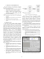
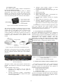
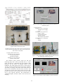
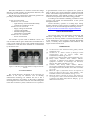
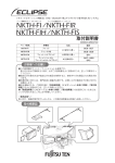
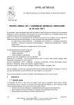
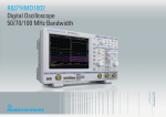
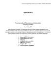
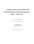
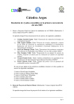
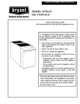
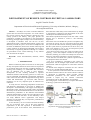
XIX IMEKO World Congress Fundamental and Applied Metrology September 6−11, 2009, Lisbon, Portugal DEVELOPMENT OF REMOTE CONTROLLED VIRTUAL LABORATORY Angéla Váradiné Szarka Department of Electrical and Electronic Engineering, University of Miskolc, Miskolc, Hungary, [email protected] Abstract − Nowadays the remote controlled industrial systems has more and more importance. Use of the internet has become general and the Ethernet cabling has been entirely spread in the industry. This paper presents the possibilities provided by the Ethernet in the measurement technology, through simple examples. The virtual laboratory is developed to introduce users into the use of most sophisticated remote controlled measurement systems The laboratory includes two parts: one is built on Fieldpoint and the other on GPIB basis, both can be used for measuring and control. Software are developed in LabVIEW. The system is used mostly in engineering education although it is suitable for presentation of the virtual technology to any Internet user interested in the subject. those functions which freely can be used without any danger to the laboratory equipment, and development of the most reliable protection methods of the system. What kind of problems developers must face when a usual Internet user is allowed to control a real laboratory equipment? Most of the users will handle the system as acceptable: they will enter the system, use it by instructions and close down the system at the end of the use switching off the equipment. But the system must be prepared also for those users, who make some mistake in use or also for unexpected system errors. For example (not a whole list): - User enters into the system, uses resources but does not do anything – leaves the computer switched on and goes for relaxation, smoking, etc. In this case nobody else can use the laboratory, but all the equipment is staying switched on. - User does not close down the system as required and all the equipment remain switched on. - User gives contradictory commands to the system (for example user sets the analogue input module to the current measurement while the equipment is connected to measure voltage) To exclude these dangerous situations the user software must be very carefully designed and tested. In this system the virtual world meets the real world and the interface between them is the control software. Software is developed in LabVIEW, which provides suitable visualisation possibilities for user interface and also provides a simple way for network connections programming with its Web Publishing Tool package. For setting up the virtual laboratory a complex information technology system must be developed. Keywords: virtual instrumentation, Ethernet, remote control 1. INTRODUCTION Remote controlled systems in all areas of our life rapidly develop and spread. Internet has more and more importance in our official and private activities, including education. Elearning and e-teaching is a comfortable and economical way of education, but to make it more effective, development of new teaching methods is required. Traditional seminars and laboratory practices in some areas can be substituted with different computerised simulations and in some areas can be done through Internet using remote control and measurement. [1]. From the other side this technology can be very important point in industrial cost reduction. To study this new technology Department of Electrical and Electronic Engineering at University of Miskolc has developed a virtual laboratory with support of the Regional Knowledge Centre. This free accessible remote controllable laboratory serves the blended education from one side and it demonstrates possibilities of the Ethernet network-based industrial measurement systems to all users through an open for all web site, from the other. “In this laboratory” users can study different sensor applications and analyse electronic circuits while they can experience possibilities of the remote controlling. As the laboratory can be accessed and used absolutely free for all Internet users, one of the most important requirements of the safe operation is determination of permissions given to the Internet users, determination of ISBN 978-963-88410-0-1 © 2009 IMEKO Figure 1. Network structure of Virtual Laboratory at the Department of Electrical and Electronic Engineering at the University of Miskolc 49 2. OBJECTIVE AND METHODOLOGY The virtual laboratory at the Department of Electrical and Electronic Engineering at the University of Miskolc includes the following subsystems: • Linear distance sensor and motor load-control measurement system with FieldPoint equipment • Complex measurement system for analysis of electronic circuits using IEEE488 protocol (equipments using GPIB standard) and GPIB controlled instrumentation. For both systems the following development steps must be done: Development of the circuits to be controlled and measured Development of measurement circuit with network interface Development of software for Internet use Testing the safe and reliable operation of the system. Figure 2. Block diagram of the GPIB system The system is connected to the traditional student laboratory experiment, several amplifying electronic circuitries, like low-pass filter, astable multivibrator, PI circuit, etc. When a user chooses between the circuits to be analysed, function generator output is connected automatically to the circuit input, and the oscilloscope to the circuit input and output. At the same time GPIB controlled power supply is switching on and provides voltage supply to the circuit and to the instruments. Students have possibility to experience advantages of computer controlled measuring system from one side – and this is the main goal, - and just testing different electronic circuits from the other. Software was developed to configure, control and measure the elements of virtual measurement system enabling to reach the remote measurement system with a simple web browser. To run the software the following elements are necessary: The circuit has to be chosen through digital outputs of DAQ operational amplifier circuit are disposable (bypass, lowpass and bandpass filter), Signal has to be generated by function generator and Measurement results might be analyzed by DMM, the oscilloscope and FFT analyzer. 2.1. GPIB based system The first system includes GPIB instruments controlled through the computer network (Internet). GPIB is a popular, worldwide standard for test and measurement system where the aim is to connect a computer and other systems. The GPIB interface is built in most of the measurement system (power supplies, function generators, oscilloscope). Serials of program and interface messages go through GPIB interface (for example status information, measurement results and control-configuration messages).GPIB instruments are easy to use instruments from the user side, because well-known instrument handling knowledge is only necessary. The IEEE488 standard consists of hard limitations for the instrumentation arrangement, which reduces the range of applicability of the system. The new generation of the GPIB controllers combines different instrument connectivity solutions with GPIB, keeping the advantages of the system and widening the instrumentation location possibilities. These combinations include serial buses, Ethernet, USB, IEEE 1394 (Firewire) and IEEE 1014 (VME bus). As one of the most widely used solutions, we decided to use Ethernet for development of GPIB system. Our instrumentation system includes an oscilloscope, digital multimeter, function generator and triple power supply [2] as follows: GPIB-ENET 100: this equipment is responsible for connecting GPIB devices and for connecting internet, TTi-PL-330P programmable power supply, TEKTRONIX TDS 1002 oscilloscope (1 GSample / sec), TTi TGA 1242 function generator: with the help of this device waveforms can be generated by setting frequency and amplitude (sin, triangle, square), MULTIPLEXER / DEMULTIPLEXER module: this module is responsible for selection of the circuit with NI-PCI-6052E DAQ card (through digital outputs). Figure 3. Virtual interface of the GPIB instrumentation system 50 • 2.2. Fieldpoint system The second system includes modular instrumentation, based on NI FieldPoint equipment. The National Instruments FieldPoint system is a flexible measurement and control system, built from modules. Modules are switched into cascade and connected to each other through the local bus connector. The 35 mm DN rail ensures fix positioning and safe connection of the modules. Analogue output module: Voltage or current generator with programmable ranges. • Counter/timer module with count inputs, gates and outputs • Digital input module • Digital output module • Digital Input/output module: programmable for receiving or sending digital signals • QUAD module: quadratic controller for stepping motors • Relay module can switch 24V or 230V • Resistance Temperature Detection module can be used with different temperature sensors and for measurement of resistance changes (strain gauges, etc). All the modules are made for industrial applications with active noise reduction. The system supports real-time, embedded applications. The modules can run applications without input from the host computer. [3] Figure 4. Network controller of the FieldPoint system The system must include an intelligent network controller, which is the central part of the system (Figure 4.). This controller has its own IP address and it is connected to the LAN on the RJ-45 Ethernet port. It also has a serial connector (RS232) to make direct connection to the PC if it is necessary. There are several status indicators on the controller giving information on the operation of the module. 2.3. User interface for system administrator The system administrator has permission to control all functions of the connected modules, it has possibility to download control program to the Fieldpoint controller or to change IP address of the controller. The figure 7. shows the administrator’s user interface windows. The only administrator can change the module functions (for example switch between the voltage or current measurement), change measurement range, or change relay module’s settings. Figure 5. Base plate and the module of the FieldPoint system The figure 5. shows general view of a module. Each module has 2 parts: one is the base, consisting Local Bus Connector and I/O connectors and the other part is the module’s electronics. Figure 7. User interface for system administrator for setting up controller and modules (Interfaces for FP-CTR-500 and FP-AO-200) Figure 6. Full system at the Department of Electrical and Electronic Engineering 2.4. Measurement examples with the FieldPoint system The interface for the Internet users is developed with strict safety limitations and with dynamic switching possibility between the measurements. The software of FieldPoint contains three measurements: 1. Testing a linear position sensor; 2. Testing a small DC motor; 3. Testing power LEDs. All the three tests include signals to be controlled by the Internet user through the analogue output and relay modules of the FieldPoint and signals measured by different sensors on the analogue inputs of the FieldPoint. The figure 6. shows a full system with the controller and 5 modules. The modules are connected in cascade through its bases. Available modules of the system: • Analogue input modules: can be used for measurement of voltage and current signals of different ranges. • Analogue input/output modules: programmable input and output connections. Range of the signals can also be programmed. 51 Figure 8. Block diagram of the Internet laboratory Figure 10. Linear sensor with motor control and user interface of FieldPoint system 2. DC motor test: Parameters to be controlled: - Voltage level of supply - Load Parameters to be measured: - Supply voltage - Current of the motor - Speed of rotation - Temperature of the motor Parameters to be calculated: - Power - Torque Figure 9. Photo of the whole system FieldPoint on the upper side; Linear sensor test on the right side; Power LEDs test on the bottom side; Motor test on the left side; Web-camera in the middle 1. Linear position sensor test: Parameters to be controlled: - movement direction - speed of movement Parameters to be measured: - position of the sensor Figure 11. Motor and generator assembly with the speed sensor and the controlling and measuring circuits The inductive linear position sensor has 100 mm measuring range and it can be positioned with a 3 V DC motor. The motor is controlled by the relay module to both directions and the speed via analogue output of the FieldPoint. The output signal of the sensor is in the range of 4-20 mA, which is measured on the current input of the FPAI module. According to the actual value of the sensor the relay can be controlled to drive the motor to both or only one direction, because if the sensor reaches one of the endpositions, the motor can be switched on to move the sensor only to the opposite direction. The measurement is visualised through a webcam to make it more attractive for studying. Figure 12. User interface of the FieldPoint system for motor test 52 to get information on the use or operation of a system. In many of these cases several parameters could be measured and/or controlled through the Internet without the need of individual presence. This method provides a cost effective solution for many distance and remote testing problems. According to the network availability presentation at the congress will include real demonstration of the system through the Internet. Virtual laboratory operates on working days during teaching semesters of the University of Miskolc from 8.am until 4.pm. It can be tested through the following web site: http://nw.elektro.uni-miskolc.hu/~angela/virtlab.html Hall effect transducers are used for current and voltage detection, a Pt100 resistance for temperature detection, and an encoder for revolution detection. The DC motor is connected to a similar DC generator for providing controllable load to the motor. 3. Test of 3 power LEDs: Parameters to be controlled: - Light intensity of each LEDs individually - Cooling fan switching on or off Parameters to be measured: - Supply voltage of each LEDs - Current of each LEDs - Summarised light intensity - Temperature of each LEDs Parameters to be calculated: - Power of each LEDs ACKNOWLEDGEMENT The research team of the Department of Electrical and Electronic Engineering of the University of Miskolc expresses the sincerely thanks to National Instruments and to the Mechatronics and Logistics Regional Knowledge Centre, to Pázány Péter Programme and NKTH for the support of this research work. Test includes 3 power LEDs of different colours: one red, one white and one green. Each LED is assembled onto a cooler. On the surface of each cooler a Pt100 termoresistant is mounted. A cooler fan can be switched on or switched off by the Internet user. REFERENCES [1] [2] [3] [4] [5] Figure 13. The three power LEDs and the cooling fan from the left side [6] 4. CONCLUSIONS The virtual laboratory developed at the University of Miskolc is not only an attractive tool of teaching measurement technology for students but also it has a practical importance for industry. In the today’s globalised world engineers must often travel from one side of the globe to the other to check a system, to find an error in a system or [7] 53 The Measurement and Automation Catalog (2002), National Instruments, USA Váradiné Sz. A.: Remote Control of Intelligent Virtual Instrumentation using the Internet. OGÉT 2005. Szatmárnémeti, Románia, pp.156-159. FieldPoint User Manual (2002), National Instruments, USA Kazup László, Unhauzer Attila, Szkárosi Szabolcs: Application of Ethernet based industrial communication equipment, Conference on Knowledge and Innovation, Miskolc, 2007. ISSN 1789-0284, pp 131-137 Unhauzer Attila, Kazup László, Szkárosi Szabolcs: Development of GPIB based virtual laboratory Conference on Knowledge and Innovation, Miskolc, 2007. ISSN 1789-0284, pp 137-147 Bátorfi R.: Effect of Information Science Development on Research of Electrical Energetics, XVII. Számokt – VIII. ENELKO Conference 2007, Romania, 2007 pp. 12-15. Bátorfi R: Software solutions for effective and reliable online diagnostics, XXII. microCAD International Scientific Confernece,19-20 March 2009, Miskolc, Hungary, pp 1-5, ISBN 978-963-661-866-9