1
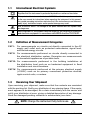
MICRO-OHMMETER ENGLISH User Manual 6240 Statement of Compliance Chauvin Arnoux®, Inc. d.b.a. AEMC® Instruments certifies that this instrument has been calibrated using standards and instruments traceable to international standards. We guarantee that at the time of shipping your instrument has met its published specifications. An NIST traceable certificate may be requested at the time of purchase, or obtained by returning the instrument to our repair and calibration facility, for a nominal charge. The recommended calibration interval for this instrument is 12 months and begins on the date of receipt by the customer. For recalibration, please use our calibration services. Refer to our repair and calibration section at www.aemc.com. Serial #: _________________________________ Catalog #: 2129.80 Model #: 6240 Please fill in the appropriate date as indicated: Date Received: __________________________________ Date Calibration Due: ________________________ Chauvin Arnoux®, Inc. d.b.a AEMC® Instruments www.aemc.com Table of Contents 1.INTRODUCTION................................................................................ 3 1.1 International Electrical Symbols.................................................4 1.2 Definition of Measurement Categories......................................4 1.3 Receiving Your Shipment...........................................................4 1.4 Ordering Information..................................................................5 1.4.1 Accessories and Replacement Parts.............................5 2. PRODUCT FEATURES....................................................................... 6 2.1 Description.................................................................................6 2.2 Applications...............................................................................7 2.3 Key Features.............................................................................7 2.4 Control Features........................................................................8 2.5 Button Functions........................................................................9 2.6 Display Symbols......................................................................10 3.SPECIFICATIONS........................................................................... 11 3.1Electrical.................................................................................. 11 3.2 Mechanical...............................................................................12 3.3Environmental..........................................................................13 3.4 Safety.......................................................................................13 4.OPERATION................................................................................... 14 4.1 Precautions Before Use...........................................................14 4.2 Instrument Configuration (SET-UP mode)...............................14 4.3 Resistance Measurements......................................................15 4.3.1 Measurement Readings...............................................16 4.3.2 Connections and Readings..........................................16 4.3.3 Test Lead Connection..................................................17 4.4 Repetitive Measurements........................................................17 4.5 Measuring Very Low Resistance.............................................18 4.6 Automatic Recording...............................................................19 4.7 Storing Results into Memory....................................................20 4.8 Recalling Results from Memory...............................................21 4.9 Erasing Measurements from Memory......................................22 4.9.1 Erasing Selected Measurements.................................22 4.9.2 Erasing All Measurements...........................................22 5.DATAVIEW® SOFTWARE................................................................. 23 5.1 Installing DataView®.................................................................23 5.2 Connecting the Instrument to your Computer..........................26 5.3 Opening the Micro-ohmmeter Control Panel...........................27 5.4 Configuring the Instrument......................................................28 5.5 Downloading Stored Tests.......................................................29 5.6 Saving/Exporting Data to a Spreadsheet or PDF File.............30 5.6.1 Saving Data to a Spreadsheet.....................................30 5.6.2 Exporting Data to a PDF from DataView®....................30 6.TROUBLESHOOTING....................................................................... 31 6.1 Error Messages.......................................................................31 6.1.1 Voltage Present...........................................................31 6.1.2 Overrange....................................................................32 6.1.3 Noisy Measurement.....................................................32 6.1.4 Overheating.................................................................32 7.MAINTENANCE.............................................................................. 33 7.1 Warning...................................................................................33 7.2 Cleaning...................................................................................33 7.3 Charging/Recharging the Battery............................................34 7.4 Battery and Fuse Replacement...............................................35 Repair and Calibration............................................................................36 Technical and Sales Assistance.............................................................36 Limited Warranty....................................................................................37 Warranty Repairs....................................................................................37 2 Micro-Ohmmeter Model 6240 CHAPTER 1 INTRODUCTION WARNING These safety warnings are provided to ensure the safety of personnel and proper operation of the instrument. • This instrument is protected from accidental voltages of not more than 50V with respect to earth in measurement Category III. • Do not attempt to perform any tests with this instrument until you have read the user manual. • Tests are to be carried out on de-energized circuits only! Never connect the unit to a live circuit. • Make sure that none of the input terminals are connected and that the switch is set to OFF before plugging in the AC power to recharge the battery of the instrument. • Make sure the internal battery is fully charged prior to testing. If the instrument has been left unused for several months, recharge the battery. • If the case needs cleaning, do not use any alcohol or oil based cleaners. Preferably use soapy water with a damp cloth or sponge. Do not immerse the 6240 micro-ohmmeter in water. • Use connection accessories of which the overvoltage category and the service voltage are greater than or equal to those of the measuring instrument (50V CAT III). Use only accessories that comply with safety standards (IEC 61010-2031). • The test leads and measuring wires must be in good condition and should be replaced if there is any evidence of deterioration (insulation split, burnt, etc.). • Troubleshooting and metrological verification procedures must only be performed by qualified, approved personnel, or the factory. Micro-Ohmmeter Model 6240 3 1.1 International Electrical Symbols Signifies that the instrument is protected by double or reinforced insulation. This symbol on the instrument indicates a WARNING and that the operator must refer to the user manual for instructions before operating the instrument. In this manual, the symbol preceding instructions indicates that if the instructions are not followed, bodily injury, installation/sample and/or product damage may result. Risk of electric shock. The voltage at the parts marked with this symbol may be dangerous. When disposed of, this product must be sorted for the recycling of electrical and electronic equipment in accordance with WEEE directive 2002/96/EC. 1.2 Definition of Measurement Categories CAT I: For measurements on circuits not directly connected to the AC supply wall outlet such as protected secondaries, signal level, and limited energy circuits. CAT II: For measurements performed on circuits directly connected to the electrical distribution system. Examples are measurements on household appliances or portable tools. CAT III: For measurements performed in the building installation at the distribution level such as on hardwired equipment in fixed installation and circuit breakers. CAT IV: For measurements performed at the primary electrical supply (<1000V) such as on primary overcurrent protection devices, ripple control units, or meters. 1.3 Receiving Your Shipment Upon receiving your shipment, make sure that the contents are consistent with the packing list. Notify your distributor of any missing items. If the equipment appears to be damaged, file a claim immediately with the carrier and notify your distributor at once, giving a detailed description of any damage. Save the damaged packing container to substantiate your claim. NOTE: Charge the instrument fully before use. 4 Micro-Ohmmeter Model 6240 1.4 Ordering Information Micro-ohmmeter Model 6240............................................. Cat. #2129.80 Includes set of two 10ft Kelvin clips (10A - Hippo), NiMH rechargeable battery pack, optical USB cable, US 115V power cord, extra large tool bag, one pad of measurement results forms, two spare fuses (12.5A), DataView® software, and user manual. 1.4.1 Accessories and Replacement Parts Kelvin clips (10A - Hippo), 10 ft color-coded leads with spade lug terminations.................................................. Cat. #1017.84 Kelvin clips (10A - Hippo), 20 ft color-coded leads with spade lug terminations.................................................. Cat. #2118.70 Kelvin Probes (1A - Spring Loaded), 10 ft with 4mm banana plug termination (includes set of 5 fork terminals)................ Cat. #2118.73 Kelvin Probes (1A - Spring Loaded), 20 ft with 4mm banana plug termination (includes set of 5 fork terminals)................ Cat. #2118.74 Kelvin Probes Pistol Grip 10 ft (10A) Spring Loaded........... Cat. #2118.75 Kelvin Probes 10 ft (10A) Spring Loaded ............................ Cat. #2118.77 Kelvin Clips 10 ft (1 to 10A).................................................. Cat. #2118.79 Kelvin Clips 20 ft (1 to 10A).................................................. Cat. #2118.80 Thermo-Hygrometer Model CA846...................................... Cat. #2121.24 Optical USB Cable............................................................... Cat. #2135.41 Replacement Battery 6.5V, 8.5AH........................................ Cat. #2129.91 Fuse, set of 5, 12.5A/500V, 6.3 x 32mm.............................. Cat. #2129.92 Extra Large Classic Tool Bag............................................... Cat. #2133.73 Inverter – 12VDC to 120VAC 200 Watt for vehicle use.......... Cat. #2135.43 Measurement Result Forms, replacement set of two........... Cat. #2129.94 115V Power Cord................................................................. Cat. #5000.14 Order Accessories and Replacement Parts Directly Online Check our Storefront at www.aemc.com/store for availability Micro-Ohmmeter Model 6240 5 CHAPTER 2 PRODUCT FEATURES 2.1Description The Micro-ohmmeter Model 6240 is used to perform low resistance measurements from 1μΩ to 400Ω. There are six ranges with test currents from 10mA to 10A. The front end of the micro-ohmmeter employs a four-wire Kelvin configuration, which eliminates test lead resistance for a measurement accuracy of 0.25%. A built-in circuit filters out AC signals. The Micro-ohmmeter Model 6240 is packaged in a sealed field case well suited for shop and field use. Power is supplied by a long-life NiMH battery pack with a built-in recharger (110/220V). The large, easy-to-read liquid crystal display is 2.25 x 4.00". It displays the value of resistance, current or voltage test, polarity and battery charge. For operator safety and instrument protection, the micro-ohmmeter is fuse protected at the inputs. One fuse, accessible from the front panel, protects against stored energy in inductive loads. Enhanced internal circuitry protects against possible inductive kickback when the current is shut off. A built-in thermal switch protects the micro-ohmmeter against overheating on the 10A range when in continuous use. 6 Micro-Ohmmeter Model 6240 2.2Applications Some of the more popular and most frequent uses of the micro-ohmmeter are in applications for: • Checking metallic coating resistance, especially in aeronautics • Ground connections and continuity measurement • Resistance measurements on motors and small transformers • Contact resistance measurements on breakers and switches • Component measurement • Electrical cable resistance measurement • Mechanical bond tests • Wire to terminal connections • Aircraft and rail bonds 2.3 Key Features • Measures from 1µΩ to 400Ω • Test current selection from 10mA to 10A • Manual temperature compensation (with DataView® software) • Front panel polarity reverse function • Stores up to 99 test results • Operator safety by automatic discharge of residual charge on the equipment under test • Instantaneous, continuous or multiple test operation • Auto store of multiple test results • Internal, rechargeable batteries conduct up to 850, 10A tests • A built-in battery pack recharger recharges the batteries by connecting to the AC line (110V-230V, 50/60Hz) using a standard line cord • 4-Wire measurement with automatic compensation of undesirable voltages and lead resistance • Large multi-function backlit display • Direct display of the measurement with units, range and test current • Rugged, sealed case Micro-Ohmmeter Model 6240 7 2.4 Control Features 2 3 5 4 ° HOLD AVG 2nd P _ COM MEMMRCLR +I I OBJ. TEST °C°F mV mA 6 V µmΩ > < DC AC 1 7 8 Figure 2-1 1. Kelvin input terminals 2. AC line recharging receptacle 3. Output fuse - 12.5A, 500V, 6x32mm 4. Large multi-line backlit liquid crystal display (see § 2.6) 5. Optical interface connector for connection to a computer 6. Range selection switch 7. Start/Stop button 8. Program/function buttons (see § 2.5) 8 Micro-Ohmmeter Model 6240 2.5 Button Functions MEM Stores the measurement at an address identified by an object number (OBJ) and a test number (TEST). Two presses on this button are required, one to select the location (use the ▲ and ► buttons to change the location) and another to store the measurement. MR Retrieves stored data except for the OFF and SET-UP positions (this function is independent of the selector setting of the switch). Data is viewed using the ▲ and ► buttons. ±I Reverses the direction of the current and displays the average. DISPLAY Displays the current or voltage on the terminals. AUTO>2s Activates automatic recordings. Used in the SET-UP and memory mode, selects a function or increments a flashing parameter. Used in the SET-UP and memory mode, accesses the function to be modified. CLR Erases the memory Micro-Ohmmeter Model 6240 9 2.6 Display Symbols The display incorporates two lines of characters to display test results, as well as a library of symbols to assist the operator in determining conditions at a glance. The symbols that can appear are shown in Figure 2-2. ° _ 2nd COM MEMMRCLR +I I HOLD AVG P OBJ. TEST °C°F mV mA V µmΩ > < DC AC Figure 2-2 Indicates the measurement is noisy; accuracy is not guaranteed Indicates the battery charge condition; the segments represent energy Indicates that power down is deactivated Not used MEM Displayed measurement about to be stored in memory MR Memory recall CLR Indicates the memory is being erased Indicates internal overheating +I Indicates the direction of current -I Indicates the direction of current Indicates that a measurement has been stopped OBJ. First position locator for data stored in memory TEST Second position locator for data stored in memory °C / °F Not used Memory utilization indicator AVG Displays average R (+I) + R (-I) 2 Not used > 10 Indicates an overrange Micro-Ohmmeter Model 6240 CHAPTER 3 SPECIFICATIONS 3.1Electrical Specifications are given for an ambient temperature of 23°C ± 3°C, relative humidity of 45 to 55%, supply voltage of 6V ± 0.2V and magnetic field of <40A/m. INPUT VOLTAGE CHECK Measurement Range 10.0 to 39.99V 40.0 to 399.99V 400 to 499V 0.01V 0.1V 1V Resolution Input Impedance 800kW Frequency Range DC and 15.3 to 450Hz RESISTANCE Measurement Range Resolution 5.0 to 3999µW 4.0 to 39.99mW 40.0 to 399.9mW 400 to 3999mW 4.0 to 39.99W 40.0 to 399.9W 1µW 10µW 100µW 1mW 10mW 100mW Accuracy Measurement current ± 0.25% ± 2ct 10.2A ± 2% (1) 1.02A ± 2% 102mA ± 2% Open voltage 10.2mA ± 2% (2) 4 to 6V (1) With nominal value of 10.2A, the measurement current is at least 10A whatever the charge condition of the battery. (2) The current is 10mA only up to 300Ω. If the battery is low, it can fall to as low as 8mA. VOLTAGE MEASUREMENT INDICATION Measurement Range Resolution 0.01 to 3.999mV 4.0 to 39.99mV 40.0 to 399.9mV 0.40 to 3.999V 4.0 to 4.70V 1µV 10µV 100µV 1mV 10mV CURRENT MEASUREMENT INDICATION Measurement Range Resolution 5.0 to 39.99mA 40.0 to 399.9mA 0.40 to 3.999A 4.0 to 11.00A 10µA 100µA 1mA 10mA Micro-Ohmmeter Model 6240 11 Influences on the Resistance Measurement Quantities of Influence Range of use Temperature Relative Humidity Variation of the measurement Typical Maximum -10 to +55°C 0.1% / 10°C 0.5% /10 °C + 2cts 10 to 85% RH @ 45°C 0.1 % 0.5% + 2cts 5 to 7V Supply Voltage 2cts 0.2% / V + 2cts Series Mode Rejection, U (AC) = (R measured x 50/60Hz* I measurement) < 0.2% 2% + 1ct Common Mode Rejection, 50/60Hz AC > 80 dB > 60 dB 0 to 50 V AC *Example: If the measured resistance is 1mΩ and the measurement current is 10A, an alternating voltage of 1mV RMS in series with the resistance to be measured will induce an error of not more than 2%. Power Supply: 6V, 8.5Ah rechargeable NiMH battery pack Battery Life: Range dependent Range Number of measurements* 10A 850 1A 3500 100mA 4500 10mA In Standby or Off 5000 battery life 4 to 6 months *Established for measurements lasting 5s, every 25s. 3.2Mechanical Dimensions: 10.70 x 9.76 x 7.17" (272 x 248 x 182mm) Weight: 10 lbs (4.5kg approx) Case Protection: ABS plastic polycarbonate: watertight to IP54 (cover closed), water resistant to IP53 (cover open). Color: Safety yellow case with gray faceplate 12 Micro-Ohmmeter Model 6240 3.3Environmental Operating Temperature: 14° to 132°F (-10° to 55°C), 10 to 85% RH Storage Temperature: -40° to 158°F (-40° to 70°C); 10 to 90% RH Altitude: <2000m NOTE: For long-term storage (>1 year) with the battery installed, the stor age range is -4 to 86°F (-20 to 30°C); 85% RH, otherwise the battery will deteriorate. For short-term storage (1 month) the temperature can reach up to 122°F (50°C). 3.4Safety Electrical safety as per EN 61010-1 (Ed. 2 of 2001), EN 61557 (Ed. 97) parts 1 and 4. Degree of pollution: 2 Protection: Measurement CAT III, 50V with respect to earth, 500V differential between terminals, and 300V CAT II on the charger input Electromagnetic Compatibility: The instrument satisfies the CEM and DBT directives required for the CE marking and product standard EN 61326-1 (Ed. 97) + A1 (Ed. 98) Emissions in residential environment Immunity in industrial environment *Specifications are subject to change without notice Micro-Ohmmeter Model 6240 13 CHAPTER 4 OPERATION NOTE: Charge the instrument fully before use. 4.1 Precautions Before Use • Never use test leads or measuring wires if there is any evidence of deterioration (insulation split, burnt, etc). • Never exceed the safety values indicated in the specifications. • Never connect the unit to a live circuit. • Never disconnect the connection wires before the from the display. 4.2 icon disappears Instrument Configuration (SET-UP mode) The SET-UP mode is used to modify the instrument’s configuration. This can also be performed by using the DataView® software that came with the instrument (see § 5). To configure the Model 6240 directly from the display, turn the rotary switch to the SET-UP position. The following screen will appear: MEM • The display order of the parameters that can be modified is: - Clear all memory (see § 4.9.2) - Time - Date - Automatic Power Off - Display of the Internal Parameters (e.g. serial number, software version, date of last calibration, lighting of all segments on display) 14 Micro-Ohmmeter Model 6240 To display and modify parameters: • To move through parameters, press the • To change the displayed parameters or view additional ones, press and hold the button. • To modify the parameters, use the • To accept the changes, press and hold the display stops blinking. 4.3 button. button. button >2s until the Resistance Measurements WARNING: Before performing the resistance test, verify that the sample under test is not energized. 1. Clean all surfaces before connecting test leads. 2. Connect the two leads to the four terminals, then the two Kelvin clips to the object to be tested. 3. Set the range selector switch to the desired range for the test. If the anticipated resistance is not known, begin with the highest range (400W) and successively lower the range selection until adequate resolution is achieved. 4. Press the START/STOP button to start the measurement. NOTE: The START/STOP needs to be pressed each time the range is changed. The range selection may be changed while the instrument is on. HOLD 5. Press the START/STOP button again to stop the measurement or disconnect one of the Kelvin clips. The last measurement made is symbol. displayed along with the Micro-Ohmmeter Model 6240 15 NOTE: If the measurement was stopped by disconnecting a Kelvin clip, simply connect it to another object to start the next measurement; It is not necessary to press the START/STOP button. 6. To display the voltage on the terminals of the resistance instead of the measurement current, press the DISPLAY key. Current results are displayed before pressing DISPLAY button Voltage results are displayed after pressing DISPLAY button 4.3.1 Measurement Readings When testing resistive samples, the meter reading will stabilize within the first few hundred milliseconds. On inductive loads (e.g. small transformers), the measurement reading may take from several seconds to a few minutes to stabilize and depends greatly on the type of equipment and the impedance of the equipment under test. 4.3.2 Connections and Readings The Model 6240 generates a current (I) from the internal voltage source (V). A voltmeter measures the voltage drop Vx at the Kelvin probe contact points to the resistance to be measured (Rx) and displays the resistance measurement (Rx) directly using the formula Rx = Vx / I. Ri I C1 Rf P2 Rf Vx P2 Rf C2 Rf + V Rc Rx Rc The result is not affected by the other Ri = Unit internal resistance resistances encountered in the current Rf = Lead resistance loop (Ri, Rf, Rc), as long as the total Rc = Contact resistance voltage drop induced across Rx remains Rx = Resistance to be measured below the voltage supplied by the source which is between 5 to 6V. The maximum admissible lead resistance level is Rf ≈ (V- Vx) / I. The use of Kelvin probes helps, as they eliminate the effect of the lead resistance (Rf). 16 Micro-Ohmmeter Model 6240 4.3.3 Test Lead Connection The measurement leads are connected using the four binding posts on the left side of the front panel as shown below. Connect the two red leads to terminals C1 and P1. Connect the two black leads to terminals C2 and P2. Any drop in the voltage on the load terminals is measured between the two “voltage” (V) leads, P1 and P2. The current leads (C1 and C2) can deliver current from 10mA to 10A. I 4.4 U Repetitive Measurements 1. Connect the Kelvin clips to the first object. Press START/STOP. 2. Disconnect the clips. The measurement stops and result is displayed. 3. Connect the clips to the second object. The measurement restarts automatically. Repeat as necessary. 4. After the last measurement, press START/STOP again. NOTE: This operation is valid only if all of the objects to be measured have substantially the same value and all of the measurements are made in the same range. Micro-Ohmmeter Model 6240 17 4.5 Measuring Very Low Resistance When measuring very low resistive values in the µΩ range, the presence of stray DC currents may affect the accuracy of the measurements. These currents can be present due to a variety of reasons including chemical or thermal EMF in samples made of dissimilar metals. You can eliminate the effects of this by reversing the direction of current flow (see example below) and using the average of forward and reverse readings. The presence of AC interference in the sample under test may cause the measured value on the display to fluctuate. This interference may become more noticeable in the presence of strong electric fields. The effects of this interference may be reduced by twisting the leads around each other. 1. Reverse the direction of the current by pressing the ±I button and the instrument displays the average: RAVG = R(+I) + R(-I) 2 2. To display the values R(+I) and R(-I), press the DISPLAY button. _I HOLD AVG A +I R(+I) +V R(+I) -I R(-I) -V R(-I) µ Ω Press the DISPLAY button to cycle through the values 18 Micro-Ohmmeter Model 6240 4.6 Automatic Recording 1. Before making measurements, press the AUTO >2s button. 2. When the button is pressed, the MEM symbol flashes and the small display indicates the first free OBJ : TEST number (e.g. 01 : 01). The . main display indicates 3. Use the use the button to switch between the OBJ and TEST option, then button to change the number of the test or object. 4. When finished, press the MEM button for >2s. Automatic recording is activated (the MEM symbol flashes). MEM +I OBJ. Use the arrow buttons to change the values of the OBJ and TEST TEST > 2s When finished, press the MEM button for > 2s 5. Press the START/STOP button to begin measuring. At each new measurement, the test number is incremented and the measurement is recorded. 6. Press the START/STOP button again to stop automatic recording. MEM P +I HOLD OBJ. TEST µ Ω Micro-Ohmmeter Model 6240 19 4.7 Storing Results into Memory Data storage is organized into objects (OBJ), each of which can contain several tests (TEST). OBJ corresponds to the object tested and each test corresponds to a measurement made on the object. The instrument can store 99 measurements. 1. Start and Stop a measurement (see § 4.3). 2. Press the MEM button. 3. When the button is pressed, the MEM symbol flashes and the small display indicates the first free OBJ : TEST number (e.g. 01 : 01). The . main display indicates 4. Use the use the button to switch between the OBJ and TEST option, then button to change the number of the test or object. 5. When finished, press the MEM button for >2s. The measurement is stored. MEM +I OBJ. TEST Use the arrow buttons to change the values of the OBJ and TEST > 2s When finished, press the MEM button for > 2s 6. If the user selects a memory address that is already occupied, appears on the main screen. To overwrite the location, press the MEM button for >2s. 20 Micro-Ohmmeter Model 6240 MEM +I OBJ. TEST > 2s either Indicates address is already occupied Display shown if memory is full: Overwrites the Memory Exits without Recording Display shown If memory is empty: MEM P +I or MR P +I OBJ. OBJ. TEST TEST 2nd 4.8 Recalling Results from Memory 1. Make sure there is no measurement in progress. 2. Press the MR button. 3. Use the and buttons to select the desired OBJ and TEST. 4. Press the MR button again to exit the memory function. Use the arrow buttons to change the values of the OBJ and TEST Micro-Ohmmeter Model 6240 21 4.9 Erasing Measurements from Memory 4.9.1 Erasing Selected Measurements 1. Press the CLR button. 2. Use the and buttons to select the desired OBJ and TEST. 3. Press the CLR button for >2s to delete the selected record. CLR +I OBJ. Use the arrow buttons to select the desired OBJ and TEST TEST > 2s µ Ω MEM +I OBJ. TEST When finished, press the CLR button for >2s 4.9.2 Erasing All Measurements 1. Turn the rotary switch to Set-up. The default display appears: MEM 2. Press for >2s. will blink. 3. Press again. will display. 4. Press again for >2s. All measurements are erased and the screen returns to the default display. 22 Micro-Ohmmeter Model 6240 CHAPTER 5 DATAVIEW® SOFTWARE 5.1 Installing DataView® DO NOT CONNECT THE INSTRUMENT TO THE PC BEFORE INSTALLING THE SOFTWARE AND DRIVERS. Minimum Computer Requirements: • Windows XP / Windows Vista & Windows 7 (32/64 bit) • 256MB of RAM for Windows XP 1GB of RAM for Windows Vista & Windows 7 (32 bit) 2GB or RAM for Windows Vista & Windows 7 (64 bit) • 80MB of hard disk space (200MB recommended) • CD-ROM drive Windows is a registered trademark of Microsoft Corporation in the United States and other countries. NOTE: When installing, the user must have Administrative access rights during the installation. The users access rights can be changed after the installation is complete. DataView® must be reinstalled for each user in a multi-user system. 1. Insert the DataView® CD into your CD-ROM drive. If auto-run is enabled, the Setup program will start automatically. If auto-run is not enabled, select Run from the Start menu and type in D:\SETUP (if your CD-ROM drive is drive D. If this is not the case, substitute the appropriate drive letter). NOTE: If installing onto a Vista based computer the User Account Control dialog box will be displayed. Select the Allow option to proceed. Micro-Ohmmeter Model 6240 23 2. A Set-up window, similar to the one below, will appear. Figure 5-1 There are several different options to choose from. Some options(*) require an internet connection. • DataView, Version x.xx.xxxx - Installs DataView® onto the PC. • *Adobe Reader - Links to the Adobe® website to download the most recent version of Adobe® Reader to the computer. Adobe® Reader is required for viewing PDF documents supplied with DataView® that are accessible from the Help menu. • *DataView Updates - Links to the online DataView® software updates to check for new software version releases. • *Firmware Upgrades - Links to the online firmware updates to check for new firmware version releases. • Documents - Shows a list of instrument related documents that you can view. Adobe® Reader is required for viewing PDF documents supplied with DataView®. 3. DataView, Version x.xx.xxxx option should be selected by default. Select the desired language and then click on Install. 4. The Installation Wizard window will appear. Click Next. 5. To proceed, accept the terms of the license agreement and click Next. 6. In the Customer Information window, enter a Name and Company, then click Next. 24 Micro-Ohmmeter Model 6240 7. In the Setup Type window that appears, select the “Complete” radio button option, then click Next. 8. In the Select Features window that appears, select the instrument’s control panel that you want to install, then click Next. NOTE: The PDF-XChange option must be selected to be able to generate PDF reports from within DataView®. Figure 5-2 9. In the Ready to Install the Program window, click on Install. 10. If the instrument selected for installation requires the use of a USB port, a warning box will appear, similar to Figure 5-3. Click OK. Figure 5-3 NOTE: The installation of the drivers may take a few moments. Windows may even indicate that it is not responding, however it is running. Please wait for it to finish. Micro-Ohmmeter Model 6240 25 11. When the drivers are finished installing, the Installation Successful dialog box will appear. Click on OK. 12. Next, the Installation Wizard Complete window will appear. Click on Finish. 13.A Question dialog box appears next. Click Yes to read the procedure for connecting the instrument to the USB port on the computer. NOTE: The Set-up window remains open. You may now select another option to download (e.g. Adobe® Reader), or close the window. 14. Restart your computer, then connect the instrument to the USB port on the computer. 15. Once connected, the Found New Hardware dialog box will appear. Windows will complete the driver installation process automatically. Shortcuts for DataView® and each instrument control panel selected during the installation process have been added to your desktop. NOTE: If you connected your instrument to the computer before installing the software and drivers, you may need to use the Add/Remove Hardware utility to remove the instrument driver before repeating the process. 5.2 Connecting the Instrument to your Computer The Model 6240 is supplied with a USB interface cable (Cat. #2135.41) necessary for connecting the instrument to the computer. This cable is equipped with a type-A USB connector on one end and an optical connector on the other end, thus providing the ability to interface with computers that have USB connectors. To connect the instrument to your computer: • Connect the optical connector end of the cable to the optical communications port on the front panel of the Model 6240. • Connect the type-A USB end of the cable to an available USB port on your computer. The first time this cable is connected to the computer, Windows will install the drivers for it. Once this has finished, the system is ready to communicate using the DataView® software with the micro-ohmmeter. 26 Micro-Ohmmeter Model 6240 5.3 Opening the Micro-ohmmeter Control Panel To open the control panel: 1. Double-click the Micro-ohmmeter Icon that was created during installation, located on the desktop. The Micro-ohmmeter Control Panel will open. Figure 5-4 2. To establish a communication link with the instrument, go to Instrument > Connect in the main menu. 3. The Communication dialog box will appear. Make sure that the communication port displayed in the dialog box matches the port that the serial cable is plugged into. Figure 5-5 4. Once the proper communication parameters have been specified, click OK. Micro-Ohmmeter Model 6240 27 5.4 Configuring the Instrument To configure the instrument perform the following steps. 1. Double-click the Micro-ohmmeter icon on your desktop. 2. Go to Instrument > Configure from the main menu of the Micro-ohmmeter Control Panel. NOTE: If a connection has not been previously established, the Communication dialog box will appear allowing you to select the Communication Port and Instrument Model. 3. Once identification is complete, the Configuration dialog box will appear on the screen, allowing you to configure the Date Format and AutoPower OFF options. Figure 5-6 This setup dialog box also contains five command buttons: • Set Clock: Programs the computer’s time and date into the configuration of the instrument. • Delete Tests: Displays a dialog box which allows the deletion of selected tests. • Write to Instrument: Programs the micro-ohmmeter using the current settings. • Read from Instrument: Reads the current configuration of the micro-ohmmeter attached via the communications cable. • Cancel: Closes the Configuration dialog box and brings up the Control Panel. Once all of the fields have been configured, click on the Write to Instrument button to configure the instrument and close the Configuration dialog box. 28 Micro-Ohmmeter Model 6240 TIP: While connected, both the DataView and Micro-ohmmeter windows may be open. They have similar main menu options. To determine which ® window is active, look at the top left corner of the window. It will either display “DataView” or “Micro-ohmmeter”. Use the Windows taskbar at the bottom of your screen to access the appropriate window. 5.5 Downloading Stored Tests The Download command initiates the transfer of test measurements stored in the instrument. To download stored tests perform the following steps: 1. Select the download command (either from the Instrument menu or the Download button). 2. The software will build a list of tests stored in the instrument and the Select Tests dialog box will appear, allowing you to select which tests to download. Figure 5-7 3. Highlight the desired tests using the Shift or Ctrl keys and select the Download button. NOTE: For additional help on using the software, use DataView’s “Help” Menu, which is located on the menu bar. Micro-Ohmmeter Model 6240 29 5.6 Saving/Exporting Data to a Spreadsheet or PDF File Measurement values stored in a database can be saved to a spreadsheet (.csv file, which can be opened in Microsoft® Excel) or exported to a PDF file (which can be opened using free Adobe® Reader software). NOTE: Exporting to a PDF file can only be performed from within DataView itself, not the Micro-ohmmeter Control Panel. 5.6.1 Saving Data to a Spreadsheet from the Control Panel To save data to a spreadsheet: 1. With a database open, go to File > Save As. 2. In the Save As dialog box that appears, choose a location to save the file from the “Save in” drop-down menu. 3. Select CSV (Comma delimited) from the “Save as type” dropdown menu, then click Save. NOTE: To be able to export the data to a PDF from the Micro-ohmmeter Control Panel, first go to File > Create Dataview Report, save as a .dvb, then open the saved .dvb file from within DataView and perform the steps below. 5.6.2 Exporting Data to a PDF from DataView® To export data to a PDF file: 1. With a database open, go to File > Generate PDF. 2. In the Print dialog box that appears, make sure that PDFXChange 3.0 is selected from the drop-down menu, then click OK. 3. When the PDF is complete, the Save As dialog box will appear. Choose a location to save it to and click Save. NOTE: Data can also be exported to a spreadsheet from within DataView by going to File > Export to Spreadsheet. 30 Micro-Ohmmeter Model 6240 CHAPTER 6 TROUBLESHOOTING 6.1 Error Messages 6.1.1 Voltage Present An error message will appear when an external voltage is present on the device being measured. (e.g. C1C2 or C1P1). Before a measurement is possible the voltage must be removed from the test object. P +I C1 or P1 V P2 >7V C2 DC A voltage greater than 20V applied across the C1-C2 terminal will cause the Fuse on the front panel to blow. (See §7.4 for fuse replacement) > 20 V C1 +I P1 HOLD A P2 C2 Micro-Ohmmeter Model 6240 Ω 31 6.1.2Overrange The > symbol indicates an overrange condition. Switch to a higher measurement range and restart the measurement until the > symbol no longer appears. +I A This symbol indicates an overrange > µ Ω 6.1.3 Noisy Measurement The symbol indicates noise in the measurement. The measurement accuracy is not guaranteed. This symbol indicates noisy measurement +I A µ Ω 6.1.4Overheating Internal overheating can occur if a measurement in the 10A range last for several minutes. No measurement is possible until the temperature symbol and indication are no longer visible. ° 32 +I Micro-Ohmmeter Model 6240 CHAPTER 7 MAINTENANCE Use only factory specified replacement parts. AEMC® will not be held responsible for any accident, incident, or malfunction following a repair done other than by its service center or by an approved repair center. 7.1Warning • To avoid electrical shock, do not attempt to perform any servicing unless you are qualified to do so. • Do not perform any service while the micro-ohmmeter is on any circuit. • To avoid electrical shock and/or damage to the instrument, do not get water or other foreign agents into the electronic module. • Make sure the internal battery is fully charged prior to testing. If the instrument has been left unused for several months, recharge the battery. • We recommend recharging the micro-ohmmeter every month to ensure a full battery charge when used. • When replacing the fuse, install only the fuse which is a direct replacement. 7.2Cleaning WARNING: Disconnect the instrument from any source of electricity. • If the case needs cleaning, do not use any alcohol or oil based cleaners. Preferably use soapy water with a damp cloth or sponge. • Dry immediately after cleaning. Avoid water penetration into the electronic module. • Make sure the micro-ohmmeter and all leads are dry before further use. Micro-Ohmmeter Model 6240 33 7.3 Charging/Recharging the Battery AC POWER SELECTION The Model 6240 may be recharged from 110 to 230VAC (50/60Hz). The instrument includes a 110V line cord, which provides the charging voltage for the rechargeable battery. CHARGING THE BATTERY • The Model 6240 should be charged to a full charge before using it for the first time. • Charging to full capacity may take up to 6 hours for a completely discharged battery. • If the battery symbol shows as an empty cell, the battery needs to be recharged. The battery will only charge in the OFF mode. • In the ON mode, the charging halts and the battery level indication is shown in the battery symbol to the top left of the display. • In the OFF mode, indication is as described in the charging indicator section below. Connect the Model 6240 to 110VAC using the power cord provided (charging starts automatically if the instrument is in the OFF mode). NOTE: Measurement can be obtained while the power cord is connected but the charging process will be stopped until the instrument is turned OFF again. CHARGING INDICATORS OFF Mode: • bAtt on the small display and ### on the main display, signifies fast charging in progress. Where ### is the percent of battery charge (only in the OFF position). • bAtt on the small display and FULL on the main display, signifies that charging is complete. At this point a low charge current is applied to maintain the battery charge. 34 Micro-Ohmmeter Model 6240 ON Mode: • bAtt shown when instrument is turned on and battery is low. There will be a 5 second delay then 4 beeps before the instrument shuts down. • bAtt shown during high current measurement indicates a low battery condition (measurement will be possible on lower current range only). Battery Indicator Status Battery Charge (C) C > 87.5% 87.5% < C < 62.5% 62.5% < C < 37.5% 37.5% < C < 12.5% 12.5% < C Blink Automatic shutdown C = 0 (battery Indicator not initialized) C=0 If the instrument is turned on and the battery voltage is >5V, then the normal use of the device is permitted. 7.4 Battery and Fuse Replacement NOTE: Make sure that no terminals are connected and that the switch is in the OFF position before removing the instrument from the case. BATTERY WARNING: Replacing the battery causes data loss from memory. • The battery should be replaced by an authorized repair facility recognized by AEMC® Instruments. See the Repair and Calibration section for return instructions. • The battery is accessible using a Phillips Head screwdriver to remove the four screws on the bottom side of the case and pulling the chassis out from the top. FUSE • The fuse is located on the front panel between the C1 and P1 input terminals. • Fuse F1, is a 6.3x32 mm, fast acting, 12.5A/500V, low internal resistance, protecting the current source from outside voltages on energized specimens. Micro-Ohmmeter Model 6240 35 Repair and Calibration To ensure that your instrument meets factory specifications, we recommend that it be scheduled back to our factory Service Center at one-year intervals for recalibration, or as required by other standards or internal procedures. For instrument repair and calibration: You must contact our Service Center for a Customer Service Authorization Number (CSA#). This will ensure that when your instrument arrives, it will be tracked and processed promptly. Please write the CSA# on the outside of the shipping container. If the instrument is returned for calibration, we need to know if you want a standard calibration, or a calibration traceable to N.I.S.T. (Includes calibration certificate plus recorded calibration data). Ship To: Chauvin Arnoux®, Inc. d.b.a. AEMC® Instruments 15 Faraday Drive Dover, NH 03820 USA Phone:(800) 945-2362 (Ext. 360) (603) 749-6434 (Ext. 360) Fax: (603) 742-2346 or (603) 749-6309 E-mail:[email protected] (Or contact your authorized distributor) Costs for repair, standard calibration, and calibration traceable to N.I.S.T. are available. NOTE: You must obtain a CSA# before returning any instrument. Technical and Sales Assistance If you are experiencing any technical problems, or require any assistance with the proper operation or application of your instrument, please call, mail, fax or e-mail our technical support team: Chauvin Arnoux®, Inc. d.b.a. AEMC® Instruments 200 Foxborough Boulevard Foxborough, MA 02035 USA Phone:(800) 343-1391 (508) 698-2115 Fax: (508) 698-2118 E-mail:[email protected] www.aemc.com NOTE: Do not ship Instruments to our Foxborough, MA address. 36 Micro-Ohmmeter Model 6240 Limited Warranty The Model 6240 is warranted to the owner for a period of one year from the date of original purchase against defects in manufacture. This limited warranty is given by AEMC® Instruments, not by the distributor from whom it was purchased. This warranty is void if the unit has been tampered with, abused or if the defect is related to service not performed by AEMC® Instruments. Full warranty coverage and product registration is available on our website at www.aemc.com/warranty.html. Please print the online Warranty Coverage Information for your records. What AEMC® Instruments will do: If a malfunction occurs within the one-year period, you may return the instrument to us for repair, provided we have your warranty registration information on file or a proof of purchase. AEMC® Instruments will, at its option, repair or replace the faulty material. REGISTER ONLINE AT: www.aemc.com Warranty Repairs What you must do to return an Instrument for Warranty Repair: First, request a Customer Service Authorization Number (CSA#) by phone or by fax from our Service Department (see address below), then return the instrument along with the signed CSA Form. Please write the CSA# on the outside of the shipping container. Return the instrument, postage or shipment pre-paid to: Ship To: Chauvin Arnoux®, Inc. d.b.a. AEMC® Instruments 15 Faraday Drive • Dover, NH 03820 USA Phone:(800) 945-2362 (Ext. 360) (603) 749-6434 (Ext. 360) Fax: (603) 742-2346 or (603) 749-6309 E-mail:[email protected] Caution: To protect yourself against in-transit loss, we recommend you insure your returned material. NOTE: You must obtain a CSA# before returning any instrument. Micro-Ohmmeter Model 6240 37 06/12 99-MAN 100324 v7 Chauvin Arnoux®, Inc. d.b.a. AEMC® Instruments 15 Faraday Drive • Dover, NH 03820 USA • Phone: (603) 749-6434 • Fax: (603) 742-2346 www.aemc.com