1
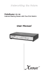
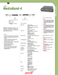
Performance with Flexibility
Patapsco PacketBand ISDN Quick Start Guide V2.01
This document is a basic guide for configuring a new Patapsco PacketBand ISDN unit.
A full User Manual for configuring all settings on the unit is supplied on the DbManager
Installation Disk (Docume nts & Manuals\PacketBand\PacketBand ISDN User Manual)
Please note, Patapsco offer an optional Pre-Configuration Service and optional Telephone Support
Agreements at minimal cost. Information on these options is in the Support document on the CD supplied.
Contents
1. In The Box
1.1 Accessories
1.2 Optional Accessories
2. Installing PacketBand
3. Installing DbManager
4. Connecting to PacketBand
4.1 Connecting via the Serial Port
4.2 Connecting Via IP
5. Configuring PacketBand - Terminal Port Drop-Down menu
5.1 Call Routing
5.2 Prioritizing Routing Profiles
5.3 Using Groups
5.4 Clock Sources
5.5 Device Settings
6. Configuring PacketBand - PRI Port Menu
7. Configuring PacketBand - BRI Port Menu
8. Configuring PacketBand - PKT Port Menu
8.1 Port Configuration
8.2 Logical Link Configuration
9. Notes on configuring PacketBand
10. Other Resources
-------------------------------------------------------------------------------------------------------------------------------------------1.
In The Box
1.1
Accessories - PacketBand ISDN is supplied with the following:
•
•
•
DbManager Installation Disk – Management Software, Documents and Manuals.
RJ12 to 9 pin ‘D’ connector Controller Cable – Serial Port Management Cable.
IEC Power Cable – Connection to mains supply.
Note: PacketBand is not supplied with an IEC Power Cable for orders outside of the UK.
1.2
Optional Accessories
The following accessories can be optionally ordered from Patapsco:
•
•
2.
ISDN Cables – A range of CAT-5 PRI and BRI cables are available.
Rack Mount Kit – Enables PacketBand to be mounted in a 19” rack.
Installing PacketBand
Mount the PacketBand in a 19” rack using the Rack Mount Kit (if ordered), or place the unit in the desired location.
•
•
•
•
3.
Connect the ISDN cables between the PacketBand’s ISDN ports and system devices/networks.
Connect the Controller Cable between PacketBand’s Terminal Port and a PC which will be used for management.
Connect an Ethernet cable between PacketBand’s PKT port(s) and the IP network/switch/router as required.
Connect the 95-250VAC 47-63Hz Mains Supply to PacketBand.
Installing DbManager
•
•
•
Insert the DbManager Installation Disk into the drive of the PC which will be used for management of PacketBand.
InstallShield Wizard will start up. Follow the steps to install DbManager.
Serial Number – Enter the Serial Number on the case of the DbManager Disk. If there is no serial number on the
case, leave the field blank and continue. DbManager will run in ‘Lite’ mode (Single user, single Device Node).
Patapsco Communications Passfield Oak, Passfield, Liphook, Hampshire GU30 7RL England
Tel: +44 (0) 1428 752900 Fax: +44 (0) 1428 752901
www.patapsco.co.uk
Performance with Flexibility
4.
Connecting to PacketBand
4.1
Connecting via the Serial Port – PacketBand can be initially connected to via the serial cable provided with the unit.
Alternatively, the default IP address can be used for IP connection to the unit (see 4.2 below).
•
•
•
Start up the DbManager Application.
Login as Super User.
Four windows will be displayed:
Devices in World – A network map showing nodes and links between Patapsco devices (Green Window).
Terminal – A view of the communications between DbManager and PacketBand (Blue Window).
Event History – All events which occur while connected to PacketBand (White Window).
Outstanding Events – Current events (White Window).
•
•
•
•
•
Select View – Properties – Terminal from the Dbmgr toolbar.
Choose the COM port which is in use. Leave the Serial Port Rate at the default setting of 19200bps. Click OK.
Select the Devices in World window and double click the Device node.
The Connect to Device window will appear. Click Connect.
The Connected to Device window should appear. This window will show a representation of the front and rear
labels on the PacketBand. If it does not, check the COM port settings and re-try.
Note: If any other applications which use the COM port are in use, please close them down when using DbManager. In
some cases it is necessary to reboot the PC after using such applications in order to free up the COM port for
DbManager to use.
4.2
Connecting via IP – Once a serial connection has been established with PacketBand, an IP Address can be configured
and an IP management connection can be made. Alternatively, the default IP address can be used to initially connect
to the unit. The default IP configuration is as follows:
IP Address:
Subnet Mask:
Default Gateway:
•
•
•
•
•
•
•
•
•
•
•
•
•
•
192.168.0.1
255.255.0.0
0.0.0.0
Connect to the PacketBand via the serial port as above. When connected, click on the Term port and select Device
Settings.
Configure the IP Address and Gateway details. Your network administrator will be able to advise you on the
correct settings to use.
Upload the changes by selecting File à Upload from the DbManager toolbar.
Go to Term à Device Settings à Reset Device and follow the steps to reset the unit.
The unit will now reset. Resetting the device will end the management connection to PacketBand and takes about 20
seconds before the PacketBand is again ready to use.
Close the Connected to Device window.
From the tool bar select View à Properties à Terminal.
Select the TCP/IP option.
Select the Device IP Addresses button and enter the IP address configured in the PacketBand.
Select OK to close the Properties window.
Hold down Ctrl and right-click on the Device node in the Devices in World window.
Click Properties and click IP List.
Select the PacketBand’s IP address from the IP list window. Click OK to save the options and exit the window.
Dbmgr is now ready to connect to the PacketBand via IP. Double click the device node and click Connect to attempt
connection over IP.
5.
Configuring PacketBand - Terminal Port Drop-Down menu
5.1.
Call Routing – Select Call Routing from the Drop-Down menu to configure routing profiles for PacketBand.
•
•
•
•
The Call Routing Profiles List is displayed. This will show all Routing Profile details when they are configured.
Select Add Profile and choose Add Routing Profile.
Name the profile and tick the Enable check-box.
Move the SOURCE PORTS radio button to Select and enter a source for incoming calls. A source can be designated
by entering a port number, port and channel number or by using a Group of ports and/or channels.
To use a port – Enter the port number (e.g. 21 for PRI 21, 1 for BRI 1)
To use a port and channel – enter the port number followed by a full stop and then the channel number (e.g. 21.1
for PRI 21 channel 1, 1.1 for BRI 1 channel 1)
To use a Group – configure a group and select it from the Drop-Down menu (see 5.2 for instructions on configuring a
group)
To connect to a remote PacketBand ISDN unit – Enter a Logical Link number 101-164 (See 8.2 for more
information on configuring Logical Links)
•
Move the DESTINATION PORTS radio button to Select, and enter a destination for calls in the same way as the
Source Ports
Patapsco Communications Passfield Oak, Passfield, Liphook, Hampshire GU30 7RL England
Tel: +44 (0) 1428 752900 Fax: +44 (0) 1428 752901
www.patapsco.co.uk
Performance with Flexibility
•
•
•
•
•
•
5.2
Select the Incoming Numbers tab to choose numbers which PacketBand will use to route the calls. If no Incoming
Numbers are configured, PacketBand will route all calls received on the Source ports to the Destination ports.
The DDI Listing defaults to */* which represents any number and any SubAddress (Number/SubAddress).
Double click the */* to edit the number values. An entry of *1234/* would route any call with a DDI ending in 1234
with any SubAddress. Right-clicking an existing entry will present more options.
Enter a CLI value if required. This is entered in the same way as the DDI. The default value; * will route calls with
any CLI.
Note: More routing options may be used to configure complex routing profiles. These are all explained in the
PacketBand ISDN manual on the Dbmgr installation disk.
Click OK on the two active windows and the new routing profile will appear in the Call Routing Profiles List
Click Exit to return to the Connected to Device window.
Prioritizing Routing Profiles - The Call Routing Profiles List shows all configured Call Routing Profiles in order of priority.
These priorities can be rearranged to allow diverse routing possibilities. When PacketBand receives a call, it will check
each profile in order from the top of the list for any routing parameters matching those of the call. It will route the call
based on the first matching profile.
•
•
•
5.3.
Select Call Routing from the Cmd port Drop-Down menu.
All configured routing profiles are displayed.
Right click on a profile in the Type column to display options. The profile can be promoted or demoted in the priority
list. There are also options to edit and delete the profile.
Using Groups – When more than one port needs to be configured as a source or destination for calls, a Group of ports
can be set.
•
•
•
•
•
•
5.4
Select Add Group from the Add Routing Profile screen.
The Group Configuration screen is displayed.
Name the Group you wish to configure (this name must not start with a digit).
Use the All and None buttons to add blocks of BRI and PRI ports to the Group, or select individual channels from
each port by using the tick-boxes.
Click OK to save the group.
The new Group will now appear in the SOURCE and DESTINATION drop-down menus. Select this Group from the
drop-down to use it in the Call Routing Profile.
Clock Sources – The PacketBand can be configured to clock from one of the following sources:
•
•
•
•
Internal – PacketBand will generate clock for the connected devices.
ISDN BRI Ports 1-8 – PacketBand will receive clock from the specified BRI port. Note that clock can only be
sourced from TE ports.
ISDN PRI Ports 21-24 – PacketBand will source clock from the specified PRI port.
Logical Links 101-164 – PacketBand will recover clock from its IP connection to another PacketBand.
The Clock Sources screen works as a hierarchy system. PacketBand will clock from the highest priority source which is
available. If the highest priority clock source is not available, PacketBand will clock from the next highest priority clock
source which is available, and so on.
•
Set priorities for each of the clock sources. 0 represents the highest priority, while 19 represents the lowest. Any
clock sources which are not going to be used can be left at the default value of 19.
Note: if one PacketBand in a system is set to clock Internally or from an ISDN port (a ‘Master’ unit), a second or third
PacketBand in the system must be configured to recover clock from their Logical Link connections to this Master unit.
IMPORTANT NOTE– Clock Sources must be configured correctly to ensure error-free operation. Please
consult the full PacketBand manual if unsure of how to configure Clock Sources.
5.5.
Device Settings – This menu controls unit-specific features of the PacketBand such as the IP Address, Identifier, Serial
Number, Configuration Number, Time & Date and Event Reporting. These features are all fully explained in the
PacketBand ISDN User Manual on the DbManager Installation Disk.
•
•
•
Enter an IP Address, SubNet Mask and Gateway for the PacketBand unit (if not previously configured for IP
connection). Your network administrator will be able to advise you on the correct settings to use.
Enter an Identifier for the unit. This Identifier will be used by DbManager to mark events relating to the unit.
Set the Time and Date if it does not match your current time zone. DbManager will timestamp events using this.
IMPORTANT NOTE: All changes to configuration need to be uploaded to the device to take effect. When
satisfied with configuration, select File à Upload from the toolbar to load the changes to the unit. Changes
in IP address will also require a reboot after the upload.
Patapsco Communications Passfield Oak, Passfield, Liphook, Hampshire GU30 7RL England
Tel: +44 (0) 1428 752900 Fax: +44 (0) 1428 752901
www.patapsco.co.uk
Performance with Flexibility
6.
Configuring PacketBand - PRI Port Menu
PacketBand can be fitted with up to 4 PRI ports . Each port is individually configurable.
•
•
•
•
•
Click the PRI port which is to be configured and select Setup Network Port.
Use the Channel Enable button to set the number of ISDN channels available on each port. Select a Port Type
(User or Network). This controls whether TE (Terminal Equipment) or NT (Network Termination) devices can be
connected to the ISDN ports.
Select the Port Type (E1 – ETSI spec or T1 – ANSI spec).
Choose whether CRC4 is to be switched On or Off. This depends on the CRC4 setting on the connected devices or
networks.
Use the Tone Generation option to set A-law Tones (euro) or µ-law Tones (US). Note that tones can only be
generated on NT ports.
The LEDs on each PRI port can be used to monitor the status of the port. The LED states show the following
information:
Top LED on
Top LED flashing
Top LED off
Bottom LED on
Bottom LED flashing
Bottom LED off
7.
-
Layer 1 and 2 established
Layer 1 established. Syncing up to Layer 2
No connectivity on interface
Calls established on interface
Calls being set-up on interface
No call traffic on interface
Configuring PacketBand - BRI Port Menu
PacketBand can be fitted with up to 8 BRI ports. Each port is individually configurable.
•
•
•
•
Click the BRI port which is to be configured and select Setup Network Port.
Use the Channel Enable buttons to set the number of ISDN channels available on each port.
Select the BRI port type Euro BRI Point to Multipoint (ETSI spec), Euro BRI Point to Point (ETSI spec) or US
BRI (ANSI spec).
Use the Tone Generation option to set A-law Tones (euro) or µ-law Tones (US ). Note that tones can only be
generated on NT ports.
The LEDs on each BRI port can be used to monitor the status of the port. The LED states show the following
information:
Top LED on
Top LED flashing
Top LED off
Bottom LED on
Bottom LED flashing
Bottom LED off
8.
-
Call active on channel 1 of BRI port
Call being set-up on channel 1 of BRI port
No call traffic on channel 1 of BRI port
Call active on channel 2 of BRI port
Call being set-up on channel 2 of BRI port
No call traffic on channel 2 of BRI port
Configuring PacketBand - PKT Port Menu
Use the PKT port menu to configure the PacketBand’s connection to the IP network and Logical Links to other
PacketBand units. Click on any PKT port to access the menu.
8.1
Port Configuration – The settings in this menu control parameters which apply to the PacketBand globally (except
where specified). The settings control the relationship between PacketBand and the IP network.
•
•
Select the Protocol Type of the IP network. Your network administrator will be able to advise you on which setting
is appropriate for your IP network.
Use the Auto-Neg button to configure the way the PKT ports will establish connections with connected devices. By
default, PacketBand will not auto-negotiate and is fixed to 100M Full-Duplex operation.
NOTE: PacketBand must have a Full-Duplex path for PacketBand traffic. The Half-Duplex setting is only
designed to be used on ports which will connect to devices which are passing traffic through PacketBand’s
on-board Ethernet switch.
8.2
Logical Link Configuration - “Logical Link” is the term used to describe the logical data connection from one
PacketBand to another over an IP network. Multiple Logical Links can be configured to allow links between many
PacketBand units. Each Logical Link can support up to 32 ISDN channels, and a unit may have up to 64 Logical Links.
•
•
•
•
Click Link Configuration and select the first Logical Link (101).
Tick the Enable box.
Use the Frames Per Packet field to dictate how many ISDN frames are encapsulated in each IP packet. See the
PacketBand user manual and PacketBand Overhead Calculator spreadsheet on the DbMgr disk for more information.
Enter the IP address of the Destination PacketBand unit.
Patapsco Communications Passfield Oak, Passfield, Liphook, Hampshire GU30 7RL England
Tel: +44 (0) 1428 752900 Fax: +44 (0) 1428 752901
www.patapsco.co.uk
Performance with Flexibility
•
Enter a value in the Jitter Buffer Length field. The Jitter Buffer will allow the PacketBand system to run across IP
networks with moderate amounts of Jitter (PDV). See the PacketBand user manual for more information.
IMPORTANT NOTE: Once the PacketBand has been configured as required, all changes to the configuration
must be Uploaded to the device before they take effect. Select File – Upload from the toolbar, and Dbmgr
will upload the changes to the unit.
9.
Notes on Configuring PacketBand
PacketBand is a two-ended solution, and it is therefore important to consider the differences between the configuration
of units in a system. The example overleaf shows two PacketBand units in a typical PacketBand application.
The Differences in configuration to be aware of between the two units are:
•
•
•
IP Addresses – The units must have different local IP Addresses and their target IP Addresses will be each other’s
local IP Address.
Clock Sources – The units will clock from different places. The Central site PacketBand will clock from TDM21 while
the other clocks from Logical Link 101, for example.
Routing Profiles – The units will have different routing profiles to control the incoming and outgoing calls.
This example requires that the PacketBands perform the following actions:
1. Route ISDN calls ending 100-102 to the VC
3. Route all calls from the ISDN phones to the ISDN
2. Route ISDN calls ending 103-105 to the ISDN phones
4. Route all calls from the VC to the ISDN
The following Call Routing Profiles must be configured on the central Site PacketBand:
Profile Number
1
2
Source Port(s)
21
101
Destination Port(s)
101
21
DDIs
*/*
*/*
The two profiles will pass all traffic from the ISDN to the Remote Site PacketBand and all traffic from the Remote Site
to the ISDN. The separating of calls between the ISDN phones and the VC will be handled by the routing profiles on
the Remote Site PacketBand:
Profile Number
1
2
3
4
5
6
7
Source Port(s)
101
101
101
101
101
101
BRI 1-6
Destination Port(s)
1
2
3
4
5
6
101
DDIs
*103/*
*104/*
*105/*
*100/*
*101/*
*102/*
*/*
This configuration will send the appropriate DDI numbers to the correct ports. All calls from the VC and ISDN phones
go out on Logical Link 101 to the Central Site PacketBand, and on to the IDSN network. BRI 1-6 have been made into
a Group to achieve this.
Patapsco Communications Passfield Oak, Passfield, Liphook, Hampshire GU30 7RL England
Tel: +44 (0) 1428 752900 Fax: +44 (0) 1428 752901
www.patapsco.co.uk
Performance with Flexibility
With all of these profiles configured, the Call Routing Profile List screen should look like this:
10.
Other Resources
The DbManager Installation disk contains the following resources to help with the configuration:
•
•
•
User Manual – The full user manual for PacketBand ISDN.
Technical Documents – Guides to help with calculating overheads and choosing the correct clock recovery type.
Example Configuration Files – Configuration files taken from a typical application which can be used as a guide.
End
Patapsco Communications Passfield Oak, Passfield, Liphook, Hampshire GU30 7RL England
Tel: +44 (0) 1428 752900 Fax: +44 (0) 1428 752901
www.patapsco.co.uk
Performance with Flexibility
Rack Mounting Kit Instructions
All Patapsco units can be mounted in a standard 19" rack housing. To allow units to fit into a 19" rack, a Rack Mounting
Kit must be purchased for the unit(s). There are various rack mounting options depending on the size of the unit ordered.
The following guide will explain how to use the Rack Mounting Kit with Patapsco units.
The Rack Mounting Kit comprises of the following:
2 x L-Brackets
4 x Rack Mount screws
4 x Rack Mount washers
4 x Rack Mount cage nuts
4 x Long Patapsco case screws
1. Remove the four short screws near the front or rear panel on the left and right hand sides of the Patapsco unit.
The unit can be mounted with the front panel facing forward or with the ports facing forward as required.
2. Fit one of the L-Brackets to the side of the unit. The four small fixing holes allow the unit to protrude forward or
sit further back depending on the desired position of the unit. The bracket may also face forwards or backwards
depending on the desired position of the unit.
3. Fix the L-Bracket in place using the Long Patapsco case screws.
4. Fix the second L-Bracket to the other side of the case in the same way.
5. Put the Rack Mount screws through the Rack Mount washers.
6. Offer the unit up to the rack and fix it in place using the Rack Mount Screws and Rack Mount cage nuts.
Patapsco Communications Passfield Oak, Passfield, Liphook, Hampshire GU30 7RL England
Tel: +44 (0) 1428 752900 Fax: +44 (0) 1428 752901
www.patapsco.co.uk