1
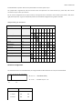
Version: 2008-04-02
Multi - XR
Contact-Multiplexer
for UPS Interfaces
User manual
GENEREX Systems GmbH Germany
Copyright 2012
Version: 2008-04-02
Function
Multi XR is a port multiplexer for ups relays contacts with Novell- and AS400 configuration. It has 5 / 10 computer ports and an
extension port to daisy chain additional Multi XRs.
It supports the signals:
AC fail
battery low
on bypass
summery alarm
In addition it allows a configurable AND connected ups shutdown from one or more computers. For shutting down Windows
systems or systems that need time to completely shut down after triggering the UPS shutdown, the ups shutdown forward can be
delayed by 1, 3 or 10 minutes.
When AC power returns before a ups shutdown has been executed, the shutdown signals are cleared and the shutdown logic goes
back to „wait“ status.
The extension port (only Multi XR10) allows you to daisy chain additional Multi XR and integrate their shutdown functionality.
CAUTION ! ! !
ALL MULTIPLEXERS MUST BE SUPPLIED OVER THE UPS POWER OUTLET BECAUSE OTHERWISE A SECURE
OPERATION IS NOT POSSIBLE IN CASE OF A PUBLIC MAINS POWER FAIL.
THE „POWER FAIL“ INPUT SIGNAL MUST BE CONFIGURED TO WORK WITH THE „POWER FAIL CLOSED“
CONTACT OF THE UPS! (SEE DIP SWITCH SETTINGS)
The output ports are isolated against each other and totally volt free. The direction of the signaling voltage does not matter,
because the multiplexer works with real relays contacts.
The ups shutdown inputs are isolated via opto couplers.
The pin functions of the ups input connector can be configured with the internal jumper field.
This way the MultiXS connects to every ups with 9 pin signal port with the attached pin to pin connected cable.
To meet the CE requirements the maximum length for the ups signal cable may not exceed 2 meters. The signal current for the ups
port is about 5 mA per signal and connected Multi XR.
For technical data, jumper functions and size of the devices please see the following tables.
Version: 2008-04-02
technical data:
power supply:
7,5 VDC ; via external power supply
max. power consumption:
750 mA
max. current through ups signal contacts:
ca. 5 mA per signal and multiplexer
max. load per output signal contact:
60 VDC / 0,1 A
pin functions at output ports:
Signal Ground:
Pin 4
AC-Fail (open):
Pin 3-4
AC-Fail (closed):
Pin 2-4
battery low
Pin 5-4
on bypass:
Pin 1-4
summery alarm:
Pin 8-4
shutdown +
Pin 6
shutdown GND
Pin 7
(Pin 4+7 for extension port)
(Pin 4+7 for extension port)
jumper settings:
The pin functions for the ups connector are configured with the internal jumper field.
procedure:
- Remove the 4 gray screw covers on the top of the device with a flat screw driver
- unlock the 4 screws and remove the top of the case.
- Check the jumper settings and correct it if necessary.
(unused jumpers should be set on only one pin for storing them)
For the connections and jumper positions see the table below.
For a correct pin configuration at the ups connector it is necessary to understand the function of the
jumper field.
Version: 2008-04-02
Put the Multi XR in a position that the rear panel with the connectors points at you.
The jumper field is organized by rows and columns. Each row represents one of the functions (i.e. power fail). Each column
connects to one pin on the ups connector.
For the correct configuration of the input connector, each signal must be connected to the connector pins (rows B, E & H) at the
right position (column). To give an example the positions for the default configuration are grayed in the table.
Jumper field „ups connector“
function (per row):
pin number at ups connector:
ups connector:
Shutdown-Signal +
row A
connector pins
row B
AC-Fail
row C
Ground
row D
connector pins
row E
Battery Low
row F
Summery Alarm
row G
connector pins
row H
On Bypass
row I
column:
Pin
1
Pin
6
Pin
2
Pin
7
Pin
3
Pin
8
Pin
4
Pin
9
Pin
5
1
2
3
4
5
6
7
8
9
Shutdown configuration
The shutdown functions and shutdown delay are configured with the DIP switches at the rear panel of the Multi XR
1 2 1 2 3 4 5 6 7 8 9 10
ON
S1.1- 1.2 = shutdown delay
ON
S2.1-2.10 = shutdown at port 1 - 10
S1
S2
shutdown delay
S1.1
S1.2
0 minutes
OFF
OFF
1 minute
ON
OFF
3 minutes
OFF
ON
Version: 2008-04-02
10 minutes
ON
ON
The DIP switches S1.1 - S1.2 set the shutdown delay. It can be set to 0, 1, 3 or 10 minutes, to allow even slower systems to shut
down before the ups shutdown is executed.
The switches S2.1 -S2.10 enable or disable the shutdown reception from port 1 - 10. To enable the shutdown function for one of
the ports, set the corresponding DIP switch to ON (switch down). If the DIP switch is in OFF position a shutdown signal at this port is
ignored and shutdown may be executed without waiting for a shutdown signal at this port.
Important note:
If one or more Multi XR are daisy chained via the extension port, at least one of the ports at the first device must have the
shutdown function enabled. Otherwise (all switches OFF) shutdown signals at the extension port are ignored. When daisy chaining
several Multi XR the shutdown delay must only be configured for the first device. Otherwise the delay times will be added up.
Display
- Power LED and 4 status LEDs for ups status at the front panel.
Quickstart
connect the Multi XR with the signal contact port of your ups, using the attached 9 pin cable.
connect the computers to the output ports.
Connect the external power supply to the Multi XR power input and a ups secured AC socket
start your ups and computers