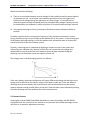
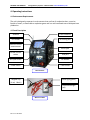
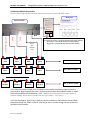
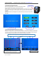
1
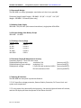
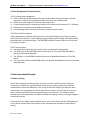
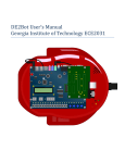
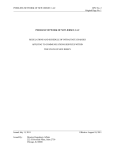
SBS-8400 USER MANUAL
Storage Battery Systems * 800-554-2243 * www.sbsbattery.com
SBS-8400 USER MANUAL
BATTERY DISCHARGE & CAPACITY TESTER
Storage Battery Systems
N56 W16665 Ridgewood Dr.
Menomonee Falls, WI 53051 USA
Tel: 800-554-2243 www.sbsbattery.com
Rev 1.1 -9-18-2012
SBS-8400 USER MANUAL
Storage Battery Systems * 800-554-2243 * www.sbsbattery.com
Contents
1. Introduction
1.1 Features
1.2 System Components
2. Technical Parameters
2.1 Environment & Condition for Use
2.2 Structure & Weight
2.3 Working Power Supply
2.4 Input Voltage from Battery Groups
2.5 Discharge Current Range
2.6 Parameter Display & Measurement Accuracy
2.7 Protection & Warning
2.8 Data Management & Communication
3. Basic Operational
3.1 Battery Testing
3.2 Constant Current
4. Operating Instructions
4.1 Environment Requirements
4.2 Panel Description
4.3 Main Machine Connection
4.4 Wireless Module Connections
4.5 Starting Up and Input Operation
4.6 Check the Connection of the Wireless Modules
4.7 The Preset Functions
4.8 Discharge
4.9 Download the Data to PC
4.10 System Setup, Activate Backup Modules & Calibration
4.11 Charge Monitoring Function
5. PC Software Instruction
5.1 Main Functions
5.2 Install Analysis Software to PC
5.3 Real-Time Recording During Testing
5.4 Download Data File from USB Disk
5.5 Generate Excel Test Report
6. Attention
7. After-Sale Service
Rev 1.1 -9-18-2012
SBS-8400 USER MANUAL
Storage Battery Systems * 800-554-2243 * www.sbsbattery.com
1. Introduction
1.1 Features
In todays ever increasing market of Critical Power applications, battery systems still remain the weakest link in the
protection of Critical loads and applications. Systems are now designed to run for a lifetime without failure, yet
inherently, the crucial factor in these applications is the age, health and welfare of the DC battery system which is
the actual source of energy during power or equipment failures. However, battery condition, performance and
reliability are all predictable factors with regular maintenance and load testing programs in place. Scheduled
maintenance and capacity tests will identify weak, aging, failing cells prior to their adverse affects of failure during
critical operations.
There are many factors which will affect the life cycle of a battery system in these applications, battery age,
operating conditions, charge characteristics, number or cycles, depth of discharge. All of these factors affect the
performance of your system and can lead to premature failures that go undetected unless preventative measures are
taken.
To guarantee your system will work when the time comes, it is necessary to do routine discharge testing to check the
capacity of your battery systems. Testing will identify weak/failing cells prior to them failing when they are needed
for operation.
With the SBS-8400, we have come up with a very useful, highly accurate and highly intellectual tool for this
purpose.
Advantages of the SBS-8400 are:
1.
2.
3.
4.
5.
6.
7.
8.
9.
10.
11.
12.
13.
Modular – Wireless battery monitoring technology. With modules capable of testing 1.2 – 2.0 VPC NiCd
Batteries, and modules capable of testing lead acid 2.0, 6.0 and 12.0 Cells.
Each module monitors 4 cells simultaneously, which reduces the number of modules required as well as
reducing the number and lengths of wires required for testing.
Online or Offline discharge testing. The SBS-8400 can simultaneously record the actual discharge currents
of each battery string in the test. (Additional current clamps are required for multi-string testing)
Discharge current stability – the SBS-8400 continuously monitors and corrects the discharge current to
maintain a constant current discharge profile during load tests.
Simple operation menus minimize the training time required to operate efficiently.
New generation alloy materials for the power consumption section allow operation at reduced
temperatures, higher safety and a reduction in size and weight.
Real time scanning and display of voltages of each battery or cell during the discharge.
Features visual and audible warning lights and alarms.
5.7 inch color LCD touchscreen. The big touchscreen allows easy adjustment and programming as well as
the ability to directly display measurements and history graphs during the discharge test process.
Intelligent analysis program monitors warning set point values and informs operator prior to test
interruption.
8 programmable preset configurations eliminates the need to reconfigure for testing similar banks of
batteries or cells.
PC analysis software that can be used during the discharge for monitoring, or downloaded via a USB
memory device for transfer to the PC for analysis and creation of reports.
Large on-board memory for storing several sets of test data between downloads to the PC Software.
The SBS-8400 also comes with an advanced analysis software program that allows:
1.
2.
3.
4.
Real time communications with a PC during Testing, or downloading of data to USB memory device for
transfer to a PC.
Software interpretation and presentation of all discharge parameters including cell voltage, system voltage,
discharge current, cell resistances, etc…
Powerful calculation functions allow for calculation actual capacities of battery or cell in the test string.
Graphic detailed reports for reviewing or printing.
Rev 1.1 -9-18-2012
SBS-8400 USER MANUAL
5.
Storage Battery Systems * 800-554-2243 * www.sbsbattery.com
Export of test data into Excel spreadsheets for data retention.
The SBS-8400 is a compact, light weight, simple to operate, and highly accurate way to meet your battery testing
needs across the whole battery size spectrum from 12 VDC to 240 VDC.
1.2
System Components
The SBS-8400 Battery Discharge and Capacity Tester consists of the Main Machine, wireless modules for
cell monitoring, wireless signal receiver, and the analysis software for the collection of data and generation of
reports.
The main machine is organized by a color LCD screen, data processing, data monitoring, auxiliary power, power
dissipation module and operating panel.
colorful LCD screen
SBS-8400 Battery
discharge &
capacity tester
main machine
data processing
wireless modules for
cells monitoring
data monitoring
PC analysis software
wireless signal
receiver
auxiliary power
power disipation
panel operation
2. Technical Parameters
2.1 Environment & Condition for Use
2.1.1 Operating temperature
-5℃~ +50℃, full power, forced-air cooling
2.1.2 Storage temperature
-40℃~ +70℃
2.1.3 Relative humidity
≤90% (40℃±2℃)
2.1.4 Altitude limit
0~2000m, -5℃~+50℃, full power
2000m~4000m, -5℃~+30℃, full power; 30℃~+50℃, decrease power for use.
Rev 1.1 -9-18-2012
SBS-8400 USER MANUAL
Storage Battery Systems * 800-554-2243 * www.sbsbattery.com
2.2 Structure & Weight
The SBS-8400 is a sturdy, lightweight, stand alone unit that is very portable.
Dimension (length*width*height): SBS-8400: 26 3/8” ×9 1/16” ×14 7/16”
Weight: SBS-8400: 53 Pounds (tester only)
2.3 Working Power Supply
SBS-8400: 110/220 VAC (with external transformer) single phase 45Hz~65Hz
2.4 DC Input Voltage from Battery Groups
SBS-8400: 10~300V
2.5 Discharge Current Range
Voltage range
Current range
8-15V
0-60 A
15-30V
0-120 A
40-60V
0-120 A
70-140V
0-120 A
140-280V
0-60 A
2.6 Parameter Display & Measurement Accuracy
Parameter display: 5.7 inch LCD color screen
Displayed discharge current:
resolution 0.1A
Displayed battery group voltage:
resolution 0.1V
Displayed cell voltage:
1.2V/2V/6V cells resolution 0.001V
12V cells resolution 0.01V
(accuracy ≤±0.5%)
(accuracy≤±0.5%)
(accuracy≤±0.05%)
(accuracy≤±0.05%)
2.7 Warning & Protection
The SBS-8400 has many built in protective features.
2.7.1 DC Input Over voltage protection, Reverse Polarity Protection, DC Current limit and
system over temperature.
2.7.2 In the event of an abnormality during testing, the warning light and buzzer will activate,
and the LCD display will alert the operator of the status of alarms.
Rev 1.1 -9-18-2012
SBS-8400 USER MANUAL
Storage Battery Systems * 800-554-2243 * www.sbsbattery.com
2.8 Data Management & Communication
2.8.1 Discharge data management
a) Tester continuously and automatically logs and saves data during tests which is stored
internally in memory and retained even when the main unit is powered off.
b) Allows for manual inspection of data via the touchscreen.
c) Communications port for reading and transfer of the data from the tester to PC / Software.
d) Displays the free memory still available on the tester.
e) Smart deleting feature: deletes all records or only the chosen record.
2.8.2 Setting Test Parameters
A Data Management Interface allows the user to set the discharge current, battery capacity,
cell numbers, the stop limit value of battery group voltage and cell voltage, discharge capacity,
discharge time in the allowed range. The SBS-8400 provides 8 Preset locations to set up tests
for common systems.
2.8.3 Communication
a) Internal wireless signal receiver records the cell monitoring & sampling data.
b) The RS232 port in the SBS-8400 machine allows your PC to connect with SBS-8400 to
display real-time discharge data.
c) The USB port in the SBS-8400 machine allows user to download the data to PC by USB
device..
d) The control port allows the SBS-8400 machine to parallel with additional units for increased
discharge rates.
3. Basic Operational Principle
3.1 Battery Testing
Due to the complexity of battery electro-chemical reactions and the variety of materials,
construction, installations, and operational environments; battery systems from different
manufacturers have many difference. Even strings of the same battery type from the same
manufacturer can vary greatly with these other factors in place. Until recently there has not
been a uniform method to determine good batteries from bad ones. The modes in which
batteries fail is still complicated, and typical methods of checking cell float or charge voltages is
not always accurate
Currently the most widely recommended practice, and in accordance with the IEEE guidelines,
is the routine maintenance of the battery system combined with periodic full load capacity
testing.
Rev 1.1 -9-18-2012
SBS-8400 USER MANUAL
Storage Battery Systems * 800-554-2243 * www.sbsbattery.com
We have learned the following:
a) There is no correlation between normal voltages in float conditions and the actual capacity
of the battery or cell. As we know, even batteries which have a very low capacity can
exhibit normal voltages during the application of a float charge. It is very difficult to
determine good from bad cells based solely on the applied float voltage. Capacity can only
be measured by the cell/battery’s ability to perform to its specifications during a load test.
b) Full capacity discharge is the only true way to effectively measure a batteries ability to
perform.
.
For battery systems that are comprised of a group of cells / batteries connected in a series
string, the entire string is only as reliable as the weakest link in the system. So the primary goal
of the battery discharge testing is to find the weakest cells and replace them to increase the
overall service life of the entire battery system.
Typically, a discharge test is conducted by applying a constant current to the system and
monitoring each individual cell / battery until the first cell reaches the low voltage limit
determined to mark the end of the test. Based on the actual data collected during this
discharge, we can determine actual true capacity of each cell.
The voltage curve in the discharging process is as follows:
Since every battery type and manufacturer will have a different discharge characteristic curve,
testing must be tailored to the specific ratings of the battery under test. There are different
discharge rates for each battery also, and test rates must be selected that test the battery
capacity without causing harmful effects to the cells. Historical data is best collected by utilizing
the same discharge rate and conditions for each consecutive test.
3.2 Constant Current
Using highly accurate PWM (Pulse Width Modulation) control technology, the SBS-8400 in
conjunction with the control unit can maintain a very accurate and constant discharge current
with little or no operator adjustment necessary..
Rev 1.1 -9-18-2012
SBS-8400 USER MANUAL
Storage Battery Systems * 800-554-2243 * www.sbsbattery.com
4. Operating Instructions
4.1 Environment Requirements
The unit is designed to operate in environments that are free of conductive dust, corrosive
liquids or fumes, no flammable or explosive gases and in a well ventilated area to dissipate heat
production.
4.2 Panel Description
Antenna
Control buttons
LCD screen
Air cooling fans
External current
measurement
RS232 port
Parallel control
socket
USB port
AC input socket
DC breaker
Power switch
Cable socket
Main machine
Power light (green)
Alligator clip
(4 red, 1 black)
Communicate light
(red)
Wireless module
Rev 1.1 -9-18-2012
SBS-8400 USER MANUAL
Storage Battery Systems * 800-554-2243 * www.sbsbattery.com
4.3 Main Machine Connections
220V AC
power source
110V AC
power source
110V AC to
220V AC
transformer
Power supply cord
DC Breaker
Power cable (black)
Power cable (red)
Battery String
4.3.1 Connect the Red (+) and Black (-) cables to the power connectors and bolt the test
cables onto the main + and main – of the battery string to be tested.
4.3.2
Use the AC power supply cord to connect SBS-8400 to an AC power source
a) SBS-8400 supports the 220V AC 50Hz/60Hz external AC power source.
b) If the power source is 110V AC 50Hz/60Hz, please use an 110V AC to 220V AC
transformer to start the tester. Because external AC power source only provides the
power for LCD and control circuit, the normal rated power of the transformer needs not
to be high.
Rev 1.1 -9-18-2012
SBS-8400 USER MANUAL
Storage Battery Systems * 800-554-2243 * www.sbsbattery.com
4.4 Wireless Module Connections
Prior to connecting any data modules pull out the antenna on the SBS-8400 tester.
Wiring Hint
Wireless module
Black
Red 3
Red 2
Red 1 (the longest one)
Wireless module number and the batteries to connect to
For example: NO.1 module -- Connect the NO.1-NO.4 (from positive electrode)
NO.2 module -- Connect the NO.5-NO.8 (from positive electrode)
NO.3 module -- Connect the NO.9-NO.12 (from positive electrode)
………..
Red 4
(the
shortest
one)
Cell
NO.1
Cell
NO.2
Cell
NO.3
Cell
NO.4
NO. 1 Wireless module
Cell
NO.5
Cell
NO.6
Cell
NO.7
Cell
NO.8
NO. 2 Wireless module
Cell
NO.4K+1
Cell
NO.4K+2
Cell
NO.4K+3
Cell
NO.4K+4
NO. N Wireless module
4.4.1 Read the module number from the label in the modules and find the right batteries to
connect with. Beginning with the most + positive (main positive) and module number 1, install
the wireless modules on the batteries / cells. Modules must be wired in the order above to
prevent damage. Never wire in groups that are not in series ( 1,3,8 9 etc.)
4.4.2 Use the alligator clips (4 red, 1 black) to connect modules to the batteries. Please follow
the proper wiring rule “Red 1 to Red 4, from long to short” and the wiring hint also printed on
the label of the modules.
Rev 1.1 -9-18-2012
SBS-8400 USER MANUAL
Storage Battery Systems * 800-554-2243 * www.sbsbattery.com
4.5 Starting Up and Input Operation
Power switch
4.5.1 After the SBS-8400 is connected to the battery system.
Turn on the AC Power switch on the front of the unit.
4.5.2 A welcome screen will appear and the main menu will display after approx.
10 seconds. Touching the screen anywhere will bring up the main menu without
the delay.
4.5.3 Menu selection and keypad entry is done directly on the touch scree of the
SBS-8400.
The welcome screen
The main menu
4.6 Check the Connection of the Wireless Modules
4.6.1 Press “Battery View” on the main menu interface. If all wireless modules are connecting
correctly, you will see the voltage of each battery displayed. If the voltages of some batteries
are not showing correctly, please check the wireless modules connections.
The highest & lowest voltage battery in battery string is displayed at the top of the screen.
Table
Next
Chart
Prev
Screen displays 24 batteries at a time, Next and
Prev. keys can be used to see more batteries.
Rev 1.1 -9-18-2012
Back to the main menu
SBS-8400 USER MANUAL
Storage Battery Systems * 800-554-2243 * www.sbsbattery.com
4.6.2 Press “Chart” to see the histogram of each battery
4.6.3 In both the table and chart interface, one screen can only show 24 batteries. If the tested
battery group has more than 24 batteries, press “Next” & “Prev” to switch screens.
4.6.4 Press “Exit” to go back to the main menu.
4.7 The Preset Functions (No Essential Operation)
4.7.1 The preset function provides for 8 locations. Test parameters can be saved and reused for
tests of the same type and quantity of batteries. The SBS-8400 also supports manual settings in
the discharge interface without using the presets.
Press “Preset” in the main menu to enter into the preset function interface.
Preset parameter number
Preset
Capacity: The rated capacity
of the tested battery group
GroupSum: the group
number for once discharging
HourRate: The hour rate of
discharge
BattLows: the quantity of the
batteries which voltages
below the “BattLow”
CurrSet: The current of
discharge(automatic change
according
“Capacity”&“HourRate”)
SaveTime: the time interval
of the data recording
CapaSet: the capacity need to
be discharged
Back to the main menu
Recover all parameter to
default values
TimeSet: the discharge time
BattLow: the lower limit
voltage of the single battery
BattSum: the battery quantity
in the battery group
To change Parameter number
Param 1, Param 2, Param 3…..
Press “Modify” to locate the preset parameters
need to be changed, “+”, “-” for change value,
“Cancel” to quit. After all setting, press “Apply”
to save
GroupLow: the lower limit
voltage of battery group
4.7.2 “CapaSet”, “TimeSet”, “BattLow”, “GroupLow” are all test termination stop conditions. If
any set value is reached, the discharge will be stopped automatically.
4.7.3 For 1 battery string discharging, the “GroupSum” should be left at “001G.” If you need 24 strings parallel discharging at one time, you will need 2-4 times wireless modules, and the
current will be divided1/2-1/4 for each group.
4.7.4 If you want the discharge to stop when one bad battery reaches the “BattLow,” please
keep “Battlows” set at “001#”. If you want the discharge to stop when N bad batteries reach
the “BattLow,” you can set the “BattLows” to the number you need.
Rev 1.1 -9-18-2012
SBS-8400 USER MANUAL
Storage Battery Systems * 800-554-2243 * www.sbsbattery.com
4.7.5 If you don’t need wireless modules during the discharge, please set the “BattSum” to
“000#”, and the “BattLow” function will be disabled.
4.8 Discharge
4.8.1 Press “Discharge” in the main menu to enter the parameter interface.
4.8.2 In the parameter interface, you will see all the same parameters in the “Preset.” You can
re-edit the discharge parameters here and “Apply” to save them.
4.8.3 Press “Start” to enter the discharge interface, then press “Start” again to start discharging
the battery string. (please remember to turn on the DC power switch first if needed).
4.8.4 Manually stopping the discharge: Press “Pause” to pause the discharge, or press “Stop” to
end the discharge. Pressing “Start” will continue the discharge.
Press “Modify” to locate the preset parameters
needed to be changed, “+”, “-” for change value,
“Cancel” to quit. After all settings are completed,
press “Apply” to save. The changes will be stored
in the preset number currently in use.
Parameter
Back to the main menu
Discharge
To load the preset you need
When the discharge starts, you will see the status in this
screen. It includes:
GroupVol: the voltage of battery group
CurrentSum: the discharge current
CapacitSum: the capacity already discharged
ConsumTim: the time since the discharge started
BattLowSum: the quantity of the batteries at voltage already
below the “BattLow” you set
MaxBatt(V): the highest voltage battery in the group
MinBatt(V): the lowest voltage battery in the group
To browse all batteries
voltage, “Table”&“Chart”
screens are similar with the
one in “BatteryView”
Change the parameters in the
process of discharging, all changes
can be activated immediately!
4.8.5 Pressing “Param” during the discharge will allow you to change parameters as needed (if
necessary). All changes activate immediately and the discharging will not be stopped.
4.8.6 “SysState:” In the discharge interface will display the status of the test.
Rev 1.1 -9-18-2012
SBS-8400 USER MANUAL
Storage Battery Systems * 800-554-2243 * www.sbsbattery.com
4.9 Download the Data to PC
4.9.1 SBS-8400 provides two ways to record the test data:
a) Use a RS232 cable to connect the main machine with a PC. Through the analysis software,
real-time test data can be downloaded during the test.
b) Internal memory always saves all testing data. You can download the data later by USB disk
or RS232 cable to the PC.
4.9.2 Press “Data” in the main menu to enter into the data interface.
Data
The used percentage of internal
memory. If this value is low, please
delete some old data
The information of the data file
Test time
& date
Delete the chosen file
Delete all data files
Back to the main menu
If the data files are more than 1
page, use “Up” “Down” to browse
Plug USB disk into the USB port,
press “USB” to download the
chosen file
Use RS232 cable to connect main
machine with PC, download the
chosen file by analysis software
4.10 System Setup, Activate Backup Modules & Calibration (No Essential Operation)
4.10.1 Press “Setup” in the main menu to enter the setup interface.
4.10.2 In the setup interface, you can use “ConfigModuleAddr” to activate the backup modules
for replacing one that is malfunctioning.
System date
& time
Setup
Press “Modify” to locate the
parameters needed to be changed,
“+”, “-” for change value
ConfigModuleAddr: Modify or
reprogram a modules ID number.
BatteryLowAct: the
automatic operation of
test stop or pause
when any battery
reaches the “BattLow”
setting.
BattOrder: wireless
module connection
order from main + or
main - of the battery
string.
Rev 1.1 -9-18-2012
Connect the module to any four
consecutive batteries. Disconnect all
other wireless modules. If you want
the module to be recognized as
module number 5, enter 005 and press
”Config”. Module is renumbered.
SBS-8400 USER MANUAL
Storage Battery Systems * 800-554-2243 * www.sbsbattery.com
4.10.3 SBS-8400 Includes a calibration function. If you have high accuracy instruments, you can
calibrate the tester yourself. Change the date to 2099-12(year-month), the “Cal” button will be
activated and appear in the right menu. Press “Cal” to enter into the calibration interface.
GroupVol: calibrate the
voltage of battery string
Dischg: calibrate discharge current
Calibrate
Press “Cal” to select the
parameters needed to be
calibrated, “+”, “-” to change
the value, “Cancel” to quit,
and “Apply” to save the
changes.
Charge: calibrate charge current
Clamp: calibrate external current clamp
TEMPE: calibrate the temperature
Back to setup interface
BattVol: calibrate the battery voltage
4.11 Charge Monitoring Function
4.11.1 Although SBS-8400 can’t charge the test battery string, it can provide a charge
monitoring function to record the values during charging.
4.11.2 Press “Charge” in the main menu to enter into the charge interface, and press “start” to
record the recharge process.
Charge
When pressing “Start” to record the charge, you can see the
status in this screen, it includes:
GroupVol: the voltage of battery string
CurrentSum: the charge current (external clamp needed)
CapacitSum: the capacity already charged (external clamp
needed)
ConsumTim: the time since the charge started
MaxBatt(V): the highest voltage battery in the group
MinBatt(V): the lowest voltage battery in the group
To browse all of the
batteries voltages,
“Table”&“Chart” screens are
similar to the one in
“BatteryView”
Rev 1.1 -9-18-2012
Back to the main menu
SBS-8400 USER MANUAL
Storage Battery Systems * 800-554-2243 * www.sbsbattery.com
5. PC Software Instruction
5.1 Main Functions
a) Recording real-time discharge data via connection between the main machine and a PC.
b) Read, display and save the downloaded USB data.
c) Generate EXCEL test reports.
5.2 Install Analysis Software to PC
5.2.1 Insert the software CD into the CD/DVD drive of the PC.
5.2.2 Follow the prompts to finish the installation.
5.2.3 After the installation, you can click the desktop icon to open the software.
PC explorer
Install program
Desktop icon
Main interface
Rev 1.1 -9-18-2012
SBS-8400 USER MANUAL
Storage Battery Systems * 800-554-2243 * www.sbsbattery.com
5.3 Real-Time Recording During Testing
5.3.1 Use the RS232 connector to connect the main machine with the PC.
RS232 wire
RS232 to USB
converter
PC
5.3.2 Choose “Connect” in the “Detect” menu to open the “RealTime Monitoring Link” interface.
Instrument types:
choose “SBS-8400” for SBS8400
Batteries Attribute: input some
information of the test battery group
(the red parameters need to be filled)
Communication Port:
Choose the COM port number (you
will find it in Device Manager)
Battery Group Count(G) Number of
parallel strings being tested at the
same time. Default is “1”.
Save Data: after all information is
entered, press “Save” to create a
“*.FGDF” file to save the real-time
data. If you are testing more than one
string at a time, you can select the
batch check mark to save all strings in
separate data files.
After saving the file, press “Connect” to wait for the real-time data
5.3.3 Ensure that data in the RED highlighted fields is correct for the batteries you are testing as
these are the numbers used to determine capacity calculations. Start the discharge of the string
from the main machine and the real time data will begin transmitting to the PC via the RS-232.
Rev 1.1 -9-18-2012
SBS-8400 USER MANUAL
Storage Battery Systems * 800-554-2243 * www.sbsbattery.com
5.3.4 The real-time data will be saved simultaneously. You can even minimize the software
during the process of discharging. The data file will continue to record the data before closing.
5.4 Download Data File from USB Disk
5.4.1 Downloading the data file from the main machine. You will see the data file named
“FGxxxxxx.FBO” (“xxxxxx” is the start time of the testing.)
5.4.2 Double click the file to activate “Date Information” screen, or you can open the software
first and choose “Open file” in the “file menu.”
PC explorer
The Software will load the parameters which you set in main machine
automatically. You can fill other non-essential information or change
the red parameters if you need to.
Main interface
Rev 1.1 -9-18-2012
SBS-8400 USER MANUAL
Storage Battery Systems * 800-554-2243 * www.sbsbattery.com
5.4.3 In the main interface, you will see 6 windows that show all of the test information:
a) Total current chart: the current during the discharging (the value is minus because
discharging)
b) Monomer curve: the voltage curve of each battery, it can be added and deleted by right
clicking on the menu.
Input the battery number range
you want to be displayed or
hidden
c)
Monomer capacity- residual capacity: Show the residual capacity, actual capacity and
capacity percent of each battery (it can be chosen to be displayed by right clicking on the
menu)
d) Data form: Show each discharge data by time interval during the discharging.
e) Monomer voltage: Each battery voltage will be displayed in the bar chart. The bar chart
will show you the initial and end voltages. Using the scroll bar in the top of this window,
you can move to any time in the testing to see the relevant result.
f)
Total voltage: the voltage curve of battery string during the discharging process.
5.5 Generate Excel Test Report
5.5.1 Press
icon to generate a report. In the “system information” window, it will show you
the number of pages in report. Choose “No” to generate an Excel report which includes all
information. If you don’t need a full report (which may have many pages), press “Yes” to
generate an Excel report, which has the page numbers you want.
Excel page choose
Generate an Excel report which
has the page numbers you want
Rev 1.1 -9-18-2012
Generate an Excel report
including all data.
SBS-8400 USER MANUAL
Storage Battery Systems * 800-554-2243 * www.sbsbattery.com
5.5.2 In the “screen data” interface, input the page numbers you want, and press “ScreenData.”
Press “CreateReport” to save the Excel report.
Generate an Excel report which
has the page numbers you want
Recover all pages of
the data file
Back to main interface
6. Attention
6.1 For safety and efficiency, please read the manual entirely before operation.
6.2 During discharge operation, we recommend the operator stay in the vicinity of the tester.
6.3 Verify the system to be tested is the same overall system voltage as the tester. Exposing the
tester to voltages above its ratings can severely damage the unit.
6.4 The wireless modules are required to be used to collect the data of each cell/battery.
Without them, the PC analysis software can’t provide the voltage drop record to estimate the
capacities.
6.5 If overheat, over current, or equipment failure happens during the discharge test, the
warning alarm will activate automatically. Please turn off the DC input switch to avoid any
further damage.
7. After-Sale Service
Storage Battery Systems, LLC. provides technical consulting and repair servicing for all of our
battery testing equipment.
If you have any technical questions or problems, please contact us:
Storage Battery Systems
N56W16665 Ridgewood Dr.
Menomonee Falls, WI 53051 USA
Tel: 800-554-2243
[email protected]
www.sbsbattery.com
Rev 1.1 -9-18-2012