1
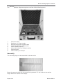
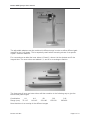
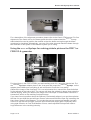
Bruker AXS
Xyclops
CCD-Camera for X-ray alignment
Instruction manual
P.O. Box 811, NL-2600 AV Delft
The Netherlands
Tel.: +31 (15) 2 512 400 Fax.: +31 (15) 2 512 500
www.bruker-axs.nl
Bruker AXS Xyclops User manual
Welcome
Thank you for purchasing the Bruker AXSXyclops, a simple and versatile tool for visualizing Xray beams from generators, monochromators, mirrors and X-ray optics. This system provides
you with an easy and simple tool to help you with optimal, fast and safe alignment of your Xray systems, either by looking at pinhole images to optimize the beam coming from your
rotating anode generator or by looking at the X-ray beam from beam conditioning devices.
Bruker AXS B.V.
Page 2 of 10
Bruker AXS Xyclops User manual
Contents
Contents...................................................................................................................................3
Camera Module .......................................................................................................................4
Setting the Camera to work ......................................................................................................4
Security and Operational notes ................................................................................................4
Specifications...........................................................................................................................4
Assembly .................................................................................................................................5
Using the Bruker AXSXyclops for basic alignment of the XOS total reflection mirrors ...................7
Using the Bruker AXSXyclops for fine adjustment of the XOS total reflection mirrors....................7
Using the Bruker AXSXyclops for alignment of Osmic Confocal MaxFlux optics ...........................8
Using the Bruker AXSXyclops for making pinhole pictures the FR571 or FR591 R.A. generator...9
Maintenance ............................................................................................................................10
Page 3 of 10
Bruker AXS B.V.
Bruker AXS Xyclops User manual
Camera Module
1.
2.
3.
Window with X-ray sensitive phosphor
Monitor connector – 75 Ω BNC Female connector
Connector for Power supply 12V DC.
Polarity: Negative ground
Setting the Camera to work
1.
2.
3.
Connect the camera to a PAL monitor or a PC with
Video Card using the 75 Ω Coaxial cable
Connect the camera to the 12V power supply
The camera is ready for use
Security and Operational notes
•
•
•
•
The camera module contains no serviceable parts and should not be opened up.
Opening of the module could damage the camera and voids the warranty.
The camera should not be subject to shock or to extreme variations in temperature.
A black protective film protects the X-ray sensitive part. Avoid touching this film with your
fingers or with any sharp object. Doing so could damage the phosphor.
Repairs to the Bruker AXSXyclops may only be carried out by qualified personnel.
Warning!
When using the Bruker AXSXyclops as a detector for X-rays, pay attention to X-ray safety.
Specifications
Operating voltage:
Current:
Temperature range:
Chip
Resolution
Signal / Noise
Magnification
Bruker AXS B.V.
9-12 V Direct current (negative ground)
approx. 100 mA
-25º C to +60º C
1/3” CCD-chip
290 000 Pixel
less or equal 48 dB
20 x
Page 4 of 10
Bruker AXS Xyclops User manual
The Bruker AXSXyclops alignment system consists of the following parts:
1.
2.
3.
4.
5.
6.
7.
8.
Camera module
Stabilised 12V Power supply
Mounting stage with magnetic base
3 different adjustable Adapter sets
Osmic Adapter (Option)
Huber Monochromator Adapter (option)
Camera holder
FR571/FR591 port Adapter
Assembly
The mounting stage can be assembled as shown below:
Mount the camera holder with the recess facing upwards. Fix the holder at the desired
height. Mount the camera on the stage.
Page 5 of 10
Bruker AXS B.V.
Bruker AXS Xyclops User manual
The adjustable adapters can be combined in different ways in order to define different path
lengths for the X-ray beam. This is especially useful when focussing mirrors for a specific
crystal – detector distance.
For convenience we label the inner tubes A, B and C, where A is the shortest and C the
longest tube. The outer tubes are labeled I, II, and III in an analogous fashion.
The three sets of inner and outer tubes will then combine in the following way to give the
below listed path lengths.
Combination
Range (mm)
A-I
75-115
A-II
110-145
B-I
150-190
B-II
155-230
C-III
225-400
Note that there is an overlap in the different ranges
Bruker AXS B.V.
Page 6 of 10
Bruker AXS Xyclops User manual
Using the Bruker AXSXyclops for a basic mirror alignment of the XOS
total reflection mirrors
Mount the camera module on the mounting stage and set the height to roughly the beam
height. Connect one of the shorter outer tubes I or II to the camera module. Position the end
of the tube as close as possible to the exit window of the mirror. Set the generator power to a
relatively low setting, approx. 30kV and 10-20 mA should be enough.
Open the X-ray shutter.
Watch the beam as a bright area on the monitor screen. Note that it may be necessary to
slightly move the camera stage sideways or the camera module up or down in order to get
the image of the X-ray beam in the center of the screen. Take care during this procedure
since X-rays could accidentally be released.
Adjust the first mirror rotation and bending until a bright line is visible above the fainter
background image. Adjust the first mirror slit to remove the overlaid background pattern until
only a thin line remains. Adjust the rotation of the first mirror until the separation between the
remaining background line and the reflected line is as large as possible but without the
intensity of the reflected beam decreasing in intensity. Turn the bending knob and watch as
the reflected line broadens as a result of defocusing or overfocusing. If the camera is very
close to the mirror then a large bending is necessary to focus the beam, if the camera is far
away, then a small amount of bending will focus the beam. When looking in the direction of
the beam, a clockwise rotation is equivalent of increasing the bend. On most mirror systems
bending and rotation are not independent and it may be necessary to adjust the rotation after
adjusting the bend.
Adjust the second mirror in an analogous fashion. After the slit for the second mirror has
been adjusted then a patterns of four spots should remain on the screen. On the XOS total
reflection mirror the upper right hand spot is the doubly reflected beam. Note that the way the
image appears on the screen is mirrored left-right in relation to how it appears when looking
at a fluorescent screen. The Bruker AXSXyclops has the same view as the “camera man”.
The second mirror normally produces a much sharper and smaller image than the first
mirror, i.e. the doubly reflected beam is smaller in the vertical direction than in the horizontal.
This is inherent in the design of the reflecting mirror and therefore the source-mirror-focus
relation is more favorable for the second mirror.
Using the Bruker AXSXyclops for fine adjustment of the XOS total
reflection mirrors
Put the collimator support and the 1.0 mm collimator on the XOS mirror. Put a 0.15 mm Ni
filter in the mirror. Remove the beamstop. Move the detector to its maximum distance. Place
the Bruker AXSXyclops mounted on its stage between the detector and the collimator system of
the XOS. Adjust the height to fit with the XOS exit. Prepare an appropriate adapter tube set.
Adjust the length of the adapter to correspond to the desired crystal-detector distance at
which the mirrors should be focussed. The crystal-detector distance is determined in the
following way: measure the full length of the adapter and then subtract 15 mm. The resulting
distance is the focussing distance as measured from the crystal position. For example if the
mirrors should be focussed at 120 mm, use the combination of inner tube A and outer tube II
and adjust to a total length of 135 mm. Now mount the adapter on the Bruker AXSXyclops . Place
it such that the inner tube fits over the collimator. Careful! The longer adapter tubes are too
heavy for the magnetic feet of the stand and they require support in both ends. Adjust the
Page 7 of 10
Bruker AXS B.V.
Bruker AXS Xyclops User manual
Bruker AXS
Xyclops left-right and up-down to place it in an approximately straight line between
collimator exit and center of the detector.
Adjust the collimator support with respect to the X-ray beam using the alignment procedure
as described in the XOS manual.
Open the shutter of the generator. Keep the power of the generator at a rather low setting
although it may in this stage of the alignment be necessary to raise the power above the
previously recommended level. At this stage a power setting of 40kV and 30-40 mA may be
necessary. If the double reflected spots is not visible it may be necessary to move the
camera left-right and up-down slightly in order to find the right position.
Note: Do not work with a too intense beam since this will cause the image to bleed out and
this reduces the spatial resolution and thus the possibility to see fine details and small
intensity variations. If the beam is too strong, reduce the current of the generator.
Open the slits of the first and second mirror slightly so that two lines rather than four discreet
spots are visible. The two lines should form a cross and the intersection of this cross
represents the doubly reflected beam. Turn the bending knob of the first mirror to focus the
horizontal line, adjust the rotation to maintain the intensity level, a clockwise rotation will
increase the reflection angle. Increase the reflection angle until the intensity becomes
weaker. Decrease the angle again to just regain maximum intensity. The mirror is now set
close the critical angle for total reflection. Repeat the procedure for the second mirror, here a
clockwise rotation will normally increase the reflection angle, however, this can be different
for some configurations. Now start closing the slits for the first and second mirror until each
line separates into two spots. Keep track of where the intersection between the lines was,
since this is the doubly reflected beam. Now put in the 0.4-mm collimator. If the doubly
reflected beam starts disappearing, use the vertical and horizontal translations of collimator
support to keep the beam visible. Put in the 0.3 mm collimator. Adjust by using the vertical
and horizontal adjustments of the collimator support.
Now close the shutter, remove the Bruker AXSXyclops and stage. Use the alignment procedure of
the Image Plate detector to optimize the position of the detector. Place the beamstop when
this is done.
Put the Bruker AXSXyclops camera module back in its carrying case. Disassemble the stand and
pack the parts in the carrying case in their place. When not used, the Bruker AXSXyclops system
should be stored in the carrying case. This will prevent parts from getting lost and/or
damaged.
Using the Bruker AXSXyclops for alignment of Osmic Confocal MaxFlux
optics
The Osmic adapter is a hollow tube with a 25mm (1”) inner diameter in one end and a 22 mm
inner diameter in the other end. This adapter is useful for doing a rough alignment of the
Osmic confocal multilayer mirrors. (note that the Osmic adapter is made to fit the Osmic exit
piece of the Osmic mirrors. Adapters for the MAR or KappaCCD will be too small).
Mount the Osmic adapter on the 25mm diameter edge tube of the Osmic mirror hosing and
mount the Bruker AXSXyclops camera module in the other end of the Osmic adapter as shown in
the figure below.
Bruker AXS B.V.
Page 8 of 10
Bruker AXS Xyclops User manual
For a description of the alignment procedure please refer to the Osmic CFM manual. For fine
alignment of the Osmic mirror, the beam guard should be replaced and the Bruker AXSXyclops
stand should be used to position the module so that the beam coming through the beam
guard can be visualized. Alternatively, use one of the tube sets and watch the beam through
the collimator or slit system of the detector system you’re using.
Using the Bruker AXSXyclops for making pinhole pictures the FR571 or
FR591 R.A. generator
Put the pinhole in the FR571/FR591 port and carefully push it in, using the pinhole tool. Put
the Bruker AXSXyclops adapter piece in the X-ray port and couple the Bruker AXSXyclops on the
adapter piece. Make sure everything is well connected. Check the X-ray safety.
Observe the image of the focal spot. If it is not a horizontal line, unscrew the three bolts that
fix the cathode to the tube a little. The vacuum will keep the cathode in place. Now rotate the
cathode slightly, while you observe the image of the focal spot. A small rotation can have a
tremendous effect on the resulting focal spot image.
If you have found a position where the filament is horizontally aligned, you can then optimize
the bias. At zero bias the spot will have “flames” above and below the spot. By increasing the
bias, these “flames” will disappear. Try to make the spot as compact as possible, but take
care not to put the bias too high, since the spot will become larger again. Especially when
using total reflection or ConFocal Maxflux mirrors, a well-adjusted focal spot will make a
huge difference in the resulting intensity.
Page 9 of 10
Bruker AXS B.V.
Bruker AXS Xyclops User manual
Maintenance
The three sets of adapter tubes are made from a material that can corrode when exposed to
an acid or humid environment. To prevent corrosion it is recommended to store these tubes
in such a way that exposure to humidity and acidic environment is minimized. If traces of
corrosion should start to occur on the tubes then cleaning them with light machine oil will
prevent further corrosion
Bruker AXS B.V.
Page 10 of 10