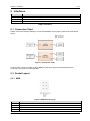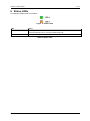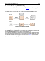
1
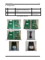
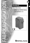
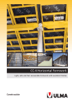
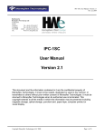
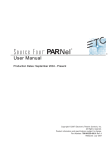
Manual – Preface 1 / 14 MDB2PC Manual Version: 1.7 Date: 29.07.2015 15:02 State: Published Updates will not be communicated actively. Classification: MDB2PC - Manual Public 29.07.15 15:02 Manual – Preface 2 / 14 Table of Contents 1 Preface ........................................................................................................................................... 4 1.1 Definitions and Abbreviations .................................................................................................. 4 1.2 References .............................................................................................................................. 4 2 Introduction ................................................................................................................................... 5 2.1 Product names ........................................................................................................................ 5 3 Safety Instructions ....................................................................................................................... 6 3.1 Warning ................................................................................................................................... 6 4 Components .................................................................................................................................. 7 5 Interfaces ....................................................................................................................................... 8 5.1 Connection Chart ..................................................................................................................... 8 5.2 Socket Layout .......................................................................................................................... 8 5.2.1 MDB ................................................................................................................................. 8 5.2.2 RS-232 ............................................................................................................................. 9 5.2.3 Low-Voltage TTL Serial ................................................................................................... 9 5.2.4 USB Virtual COM-Port ................................................................................................... 10 6 Status LEDs ................................................................................................................................. 11 7 Changing Master / Slave Modes ................................................................................................ 12 8 Control Protocol (MDB2PC CP) ................................................................................................. 13 9 SDK .............................................................................................................................................. 14 MDB2PC - Manual 29.07.15 15:02 Manual – Preface 3 / 14 Table of Figures Figure 1: MDB2PC Master Edition ....................................................................................................... 7 Figure 2: MDB2PC Slave Edition ......................................................................................................... 7 Figure 3: MDB2PC Master Edition USB (Beta Only) .............................................................................. 7 Figure 4: MDB2PC Serial Cable .............................................................................................................. 7 Figure 5: MDB2PC in Housing ................................................................................................................ 7 Figure 6: MDB2PC USB in Housing ........................................................................................................ 7 Figure 7: Connection Chart ..................................................................................................................... 8 Figure 8: MDB Socket Layout ................................................................................................................. 8 Figure 9: RS-232 Socket Layout (P4) ..................................................................................................... 9 Figure 10 Low-Voltage TTL Serial Socket Layout (P5) ........................................................................... 9 Figure 11: Status LEDs ......................................................................................................................... 11 Figure 12: Control Protocol Overview ................................................................................................... 13 List of Tables Table 1: Definitions and Abbreviations .................................................................................................... 4 Table 2: References ................................................................................................................................ 4 Table 3: MDB2PC components ............................................................................................................... 7 Table 4: Interfaces ................................................................................................................................... 8 Table 5: MDB Socket Pins....................................................................................................................... 9 Table 6: RS-232 Socket Pins (P4) .......................................................................................................... 9 Table 7: RS-232 Socket Specification (P4) ............................................................................................. 9 Table 8: Low-Voltage TTL Serial Socket Pins (P5) ................................................................................. 9 Table 9: Status LEDs ............................................................................................................................. 11 Table 10: Description of SDK Source Code Projects ............................................................................ 14 MDB2PC - Manual 29.07.15 15:02 Manual – Preface 4 / 14 1 Preface 1.1 Definitions and Abbreviations Item Description CP See Control Protocol (MDB2PC CP) MDB2PC The actual MDB2PC device. ESD electrostatic discharge EMC electromagnetic compatibility MDB MDB vending machine protocol according to [mdb]. PC Personal computer. For simplicity used in this document to describe any RS 232 devices. RS232 device A device that supports the RS232 serial protocol. Usually this is a PC. Table 1: Definitions and Abbreviations 1.2 References Ref. Description Version / Date [mdbcp] MDB2PC Specification Abrantix MDB2PC Control Protocol.pdf - [mdb] NAMA Multi Drop Bus / Internal Communication Protocol MDB / ICP 4.2 / Feb. 2011 Table 2: References MDB2PC - Manual 29.07.15 15:02 Manual – Introduction 5 / 14 2 Introduction The MDB2PC is a device that allows connecting any RS232 capable device to an MDB capable vending machine. The MDB2PC understands the MDB 9 bit protocol and tunnels the MDB payload in a proprietary 8 bit protocol that can be understood by the RS232 device (s. Control Protocol (MDB2PC CP)). This allows implementing an MDB master or peripheral application on an RS232 device. The MDB2PC is available in either a Master or a Salve edition. The Master edition can also be operated in MDB slave mode and the Slave edition can only be operated in MDB slave mode. The MDB slave mode supports MDB cashless peripherals and coin changers as defined in [mdb]. Other slave peripherals can be implemented with the MDB2PC, but no support is provided. Please contact Abrantix for further information. For technical details and the protocol specification, please refer to [mdbcp]. 2.1 Product names We constantly improve the MDB2PC to suit the needs of our clients. These improvement can be firmware or hardware changes. Changes are not actively communication to clients. Firmware changes and smaller hardware changes will not lead to a change of the product name. Bigger hardware changes will lead to the change of the product name. Therefore we added a number in the end of the product name. This number will be increased with each bigger hardware change. In this document, the term MDB2PC is used for all product versions and editions, and also stands for MDB2PC2 or any other future version. MDB2PC - Manual 29.07.15 15:02 Manual – Safety Instructions 6 / 14 3 Safety Instructions While working with the MDB2PC you must follow the rules defined by ESD (electrostatic discharge). While working with the MDB2PC you must follow the rules defined by EMC (electromagnetic compatibility). Any manipulation on the MDB2PC is only allowed after you have disconnected the power source (MDB plug) or after you have de-powered the whole vending machine. It is not allowed to open the MDB2PC. The violation of this rule eliminates any warranty. Only qualified and trained people are allowed to install and manipulate the MDB2PC. Protect the MDB2PC from liquids. Never let the MDB2PC get in contact with any liquids. Never try to connect the MDB2PC with any other electronic devices that are not defined in this document or that are not provided by Abrantix. After a power down of the MDB2PC, wait at least five second before you re-power the device. Never try to open the MDB2PC or unscrew the housing. Never try to manipulate the MDB2PC if you are not a qualified and trained person. Violation of this rule can damage or destroy the MDB2PC. Always call Abrantix in the following cases: The MDB2PC got in touch with liquids The MDB2PC was dropped and the housing is damaged The MDB2PC shows significant changes in its operating behavior. Please verify that you operate the MDB2PC only under the allowed temperature range (10 degree Celsius to 50 degree Celsius) Use the MDB2PC only for its Intended Use. 3.1 Warning The MDB2PC must be installed and operated according to the user manual. MDB2PC - Manual 29.07.15 15:02 Manual – Components 7 / 14 4 Components Pos. Name Description Size (cm) L * W * H 1 MDB2PC Board Either the master or the slave edition can be used. The master edition is also available with USB interface instead of a serial interface (beta only). See below. 9.8 * 5.2 * 2.1 approx. 2 MDB2PC Serial Cable Optional Length: 105 approx. 2 MDB2PC Housing Optional 10.8 * 6.6 * 2.2 approx. (Height plus approx. 1 cm for sockets sticking out) Table 3: MDB2PC components Figure 1: MDB2PC Master Edition Figure 2: MDB2PC Slave Edition Figure 3: MDB2PC Master Edition USB (Beta Only) Figure 4: MDB2PC Serial Cable Figure 5: MDB2PC in Housing Figure 6: MDB2PC USB in Housing MDB2PC - Manual 29.07.15 15:02 Manual – Interfaces 8 / 14 5 Interfaces Name Interface MDB MDB Interface to the vending machine MDB (Power) MDB Interface for power supply (in Master Mode only) Serial Interface to connect or a RS232 device USB Interface to connect or a USB device (Beto only) Table 4: Interfaces 5.1 Connection Chart Please refer to the following drawing to connect the MDB2PC to the vending machine and the RS232 device: Figure 7: Connection Chart In slave mode, it does not matter to which MDB plug the power supply and the peripherals are connected. The plugs are interchangeable. 5.2 Socket Layout 5.2.1 MDB Figure 8: MDB Socket Layout Pin Description 1 12 - 38 VDC 2 DC Power Return 3 N/C 4 Master Receive MDB2PC - Manual 29.07.15 15:02 Manual – Interfaces 9 / 14 5 Master Transmit 6 Communications Common Table 5: MDB Socket Pins Absolute Maximum Voltage = 42.5 VDC (ripple voltage upper limit) (according MDB / ICP Hardware specification). 5.2.2 RS-232 Not available on MDB2PC USB Version. 1 2 3 4 5 6 7 Figure 9: RS-232 Socket Layout (P4) Pin Description 1 5 VDC out, max. 0.5 A1. Do not connect any power source to this Pin! 2 RS-232 TX (DCE) 3 RS-232 RX (DCE) 4 N/C (GND) 5 N/C (GND) 6 GND 7 GND Table 6: RS-232 Socket Pins (P4) Vendor Part Number Description Molex 51004-0700 Connector Housing Molex 50011-8000 Crimping Contacts Tin 24-30AWG Molex 63819-1000 Hand Crimping Tool Table 7: RS-232 Socket Specification (P4) 5.2.3 Low-Voltage TTL Serial The MDB2PC LV-TTL I/O Connection Option1 bypasses the standard RS-232 interface and allows to communicate directly to the MDB2PC Microprocessor. . P5 1 Figure 10 Low-Voltage TTL Serial Socket Layout (P5) Pin Description 1 RS-232 Transceiver. In RS-232 Mode over Socket P4 [5.2.2], Pin 1 and Pin 2 must be connected using a Jumper. Remove the jumper for Low-Voltage TTL Serial use. Do not connect anything other to this pin. 2 3.0V LV-TTL RX (DCE) 3 3.0V LV-TTL TX (DCE) 4 GND 5 VDC out, max. 0.5 A. Do not connect any power source to this Pin! 5 Table 8: Low-Voltage TTL Serial Socket Pins (P5) 1 Only available on MDB2PC Version 2. MDB2PC - Manual 29.07.15 15:02 Manual – Interfaces 10 / 14 5.2.4 USB Virtual COM-Port Only available on MDB2PC USB Version. The USB On-The-Go (OTG) Micro-B Receptacle (J5) provides a Virtual COM-Port VCP Interface using a FTDI FT-230x USB to Serial Interface driver. This VCP chipset is supported by all major Operating Systems. MDB2PC - Manual 29.07.15 15:02 Manual – Status LEDs 11 / 14 6 Status LEDs The following status LEDs are provided: Figure 11: Status LEDs LED Status LED 1 Shows operational state. Continuous blinking (0.5s on, 0.5s off) indicates status OK. LED 2 Internal use only. (Flash mode) Table 9: Status LEDs MDB2PC - Manual 29.07.15 15:02 Manual – Changing Master / Slave Modes 12 / 14 7 Changing Master / Slave Modes The MDB2PC Master edition can also be operated as an MDB Slave. The following steps allow changing an MDB2PC Master to a slave or back to a master: 1. 2. 3. 4. 5. 6. 7. 8. Start the SDK GUI Choose tab MDB Slave and Direct Serial Select the active COM Port and click Start Choose command MDB Mode = SLAVE, or MDB Mode = Master, respectively Click Send You should receive an ACK Now the mode (master or slave) is permanently save in flash memory Change the DIP switches as indicated on the PCB MDB2PC - Manual 29.07.15 15:02 Manual – Control Protocol (MDB2PC CP) 13 / 14 8 Control Protocol (MDB2PC CP) The control protocol is a proprietary, serial 8 bit protocol designed by Abrantix. Any device wanting to connect to the MDB over the MDB2PC must implement this protocol. This chapter shall only give a brief overview of the CP. The CP specification can be found in [mdbcp]. The following drawing shows the usage of the control protocol for the different MDB2PC modes. Figure 12: Control Protocol Overview The CP is an asynchronous, full duplex protocol established between the PC and the MDB2PC. Its main purpose is to frame the payload received from the MDB into an 8 bit format understood by the PC. The MDB payload is not altered by the CP. This way, the PC is free to send and receive any MDB command and the MDB state machine can easily be implemented on the PC. The CP defines the message framing (simple STX...DLE ETX framing) and the message flow used for communication between the two devices. Also, it defines various control codes that define the nature of a frame being transmitted. The most common control code is DATA [mdbcp], which indicates that the frame contains the unmodified MDB payload. Other control codes are available; these can be used by the PC to obtain information regarding the state of the MDB2PC. MDB2PC - Manual 29.07.15 15:02 Manual – SDK 14 / 14 9 SDK The SDK is a Visual Studio 2010 sample solution written in C#. It shall help to implement applications using the MDB2PC. The SDK is provided as is. Abrantix disclaims any liability for the code. The code is more a sample than a production implementation, but it shows how simple it is to develop applications for the MDB2PC and shows the general idea on how the Control Protocol (MDB2PC CP) shall be implemented. It is very likely that certain commands must be tweaked to achieve a stable running application. Also, it shall be remarked that each vending machine model runs its own dialect of MDB. Depending on this dialect, more or less tweaking is necessary. The SDK consists of the following projects: Project Description Abrantix.MDB2Serial.Common Common code shared over all projects, such as MDB commands specified in [mdb]. Abrantix.MDB2Serial.MDBSimulator The actual master (MasterSimulator.cs) and slave (CashlessDeviceSimulator.cs) sample code. Refer to these files as a first step. The file SerialDriver.cs contains the control protocol implementation [mdbcp]. Abrantix.MDB2Serial.MDBSimulatorUI The UI. Use this project as the startup project. When started, the tabs MDB Master Simulator and Cashless Device Simulator are of interest. Table 10: Description of SDK Source Code Projects MDB2PC - Manual 29.07.15 15:02