1
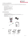
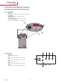
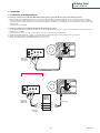
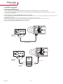
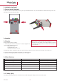
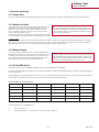
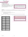
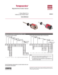
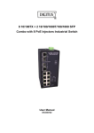
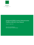
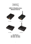
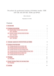
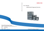
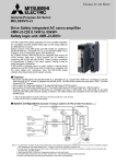
Temposonics®
Absolute, Non-Contact Position Sensors
M-Series
Analogue/PWM Tester
User’s Manual
Document Part Number
551132 Revision B
M-Series Tester
User’s Manual
Content
1 The M-Series analogue/PWM Test Kit
1.1 Contents and accessories
1.2 Familiarizing yourself with the M-Series Tester
1.2.1 Front panel
1.2.2 Top panel
2 Installation
2.1 Connecting analogue sensors
2.2 Connecting PWM sensors
2.3 Battery charger setup
2.4 AC power plug
2.5 Quick start instruction label
2.6 Carrier handle adjustment
3 Operation
3.1 Startup
3.2 Mode selection
3.2.1 Voltage (Volt)
3.2.2 Current (Curr)
3.2.3 Battery level (Batt)
3.2.4 Battery charging
3.2.5 Scaled PWM (Puum)
3.2.6 PWM time of flight (TOF)
3.3 Verification
3.4 Troubleshooting
MTS Sensors
I2I
M-Series Tester
User’s Manual
1. The M-Series analogue/PWM Test Kit
The M-Series analogue/PWM Tester supports analogue, 0 - 20 mA and 0 - 10 Vdc, scaled Pulse Width Modulated (PWM), and PWM time of flight (tof) sensor outputs. The M-Series Tester is a battery powered device that can be used in test bench and field applications to verify that the MTS Sensor is functioning properly and
is producing the appropriate signal outputs.
• Easy connection to MTS’ M12 integrated connector system
• Easy to use push-button controls
• Supports voltage (0-10 Vdc) and current (0-20 mA) outputs
• Tolerances 5 Vdc – 10 mV, 20 mA – 0,02 mA
• Supports scaled PWM and time-of-flight PWM outputs
• Compact construction for use in field applications
• Provides both +5 Vdc and +12/24 Vdc sensor power supply
• Battery that provides up to 8 hours of operation per charge
• Battery level monitoring
• Automatic detection of PWM sensor frequency
• Carrying case
1.1 Content and Accessories
The M-Series analogue/PWM Test Kit includes:
1. M-Series analogue/PWM Tester (254 025)
2. 12 VDC battery charger with adapter EU/UK (380 090)
3. Cable with MTS’ M12*1 integrated connector system and banana plugs pin 2-3-4 (253 869) for pin assignment E
4. Cable with MTS M12*1 integrated connector system and banana plugs pin 1-3-4, pin 1-3-2 (254 204) for pin assignment G and H
5. Pigtailed cables with banana plugs (253 870) (not pictured)
6. Carrying case (590 138)
7. User’s Guide (not pictured)
7. Quick start instruction label (not pictured)
1
2
3/4
6
Accessories
Power Plug Adapter
North America
Part No. 370573
Power Plug Adapter
Europe
Part No. 370572
I3I
Power Plug Adapter
United Kingdom
Part No. 370574
MTS Sensors
M-Series Tester
User’s Manual
1. The M-Series analogue/PWM Test Kit (continued)
1.2 Familiarizing yourself with the M-Series Tester
1.2.1 Front panel
1. LCD panel
Tester LCD panel displays sensor output, settings, and battery level
2. Power switch
Toggle to turn the M-Series Tester ‘ON’ and ‘OFF’.
3. Mode button (A)
Press to change transducer modes and to reset system.
4. Special function button (B)
Press to change recirculation values in PWM TOF mode
2
1
4
3
2
4
5
6
GND
ANA
PWM
1.2.2 Top Panel
1. Charger port
Port used to charge the battery
2. +5 V
Sensor 5 volt supply connection (Not an input port)
3. +12 V
Sensor 12 volt supply connection (Not an input port)
4. GND
Sensor ground connection.
5. ANA
Connection for sensors with analogue output signal.
6. PWM
Connection for sensors with PWM/TOF output signal.
1
+5V
+
−
+12V
3
MTS Sensors
I4I
M-Series Tester
User’s Manual
2. Installation
2.1 Connecting an analogue Sensor
To connect an analogue sensor equipped with MTS’ M12 integrated connector system to the M-Series Tester use the following procedure:
1. Use the provided cabling fitted with the M12 connector and connect the M12 cable to the MTS M12 integrated connector system on the sensor or cylinder.
Please pay attention to the pin assignment of the sensors. Sensors with pin assignment 2-3-4 (e.g. N10E) have to be connected with the M12*1 cable with the
connector colours brown, white and green. For sensors with pin assignment 1-2-3 (N10H) or 1-3-4 (N10G) please us the cable with the connector colours black,
white and green.
(continue with step 3 below) OR
To connect an analogue sensor not equipped with MTS’ M12 integrated connector system:
1. Use the Pigtailed cable that is included in the test kit to connect the ends without banana plugs to the customer’s specified interface/connector that mates to the
M-Series sensor or cylinder.
2. Ensure that the wire colors of the cable correspond with the wire colors of the output wires from the sensor.
3. Plug the brown banana plug into the +12 Vdc or +5 Vdc (depending on voltage required by the sensor) terminal on the top of the tester.
4. Plug the white banana plug into the DC GND terminal on the top of the tester.
5. Plug the green banana plug into the analog terminal at the top of the tester.
+5V
GND
+
−
PWM
ANA
White
Black / Brown
Select sensor
supply voltage
(+12 V or +5 V)
Green
+12V
M12 Cable Assembly
Attention! Please take care of the sensor type.
+5V
GND
+
−
ANA
PWM
Green
White
Brown
+12V
Select sensor
supply voltage
(+12 V or +5 V)
CUSTOMER
SPECIFIED
INTERFACE/
CONNECTOR
Sensor cable
Green
Green
White
White
Brown
Brown
Pigtail cable
assembly
I5I
MTS Sensors
M-Series Tester
User’s Manual
2. Installation (continued)
2.2 Connecting PWM Sensors
To connect a PWM sensor equipped with MTS’ M12 integrated connector system to the M-Series Tester use the following procedure:
1. Use the provided cabling fitted with the M12 connector and connect the M12 cable to the MTS M12 integrated connector system on the sensor or cylinder.
(continue with step 3 below) OR
To connect a PWM sensor not equipped with MTS’ M12 integrated connector system:
1. Use the Pigtailed cable that is included in the test kit to connect the ends without banana plugs to the customer’s specified interface/connector that mates to the
M-Series sensor or cylinder.
2. Ensure that the wire colors of the cable correspond with the wire colors of the output wires from the sensor.
3. Plug the brown banana plug into the +12 Vdc or +5 Vdc (depending on voltage required by the sensor) terminal on the top of the tester.
4. Plug the white banana plug into the DC GND terminal on the top of the tester.
5. Plug the green banana plug into the PWM terminal at the top of the tester.
+5V
GND
+
−
ANA
PWM
Green
Select sensor
supply voltage
(+12 V or +5 V)
White
Brown
+12V
M12 Cable Assembly
+5V
GND
+
−
PWM
ANA
Green
White
Brown
+12V
Select sensor
supply voltage
(+12V or +5V)
CUSTOMER
SPECIFIED
INTERFACE/
CONNECTOR
Sensor cable
Green
Green
White
White
Brown
Brown
Pigtail cable
assembly
MTS Sensors
I6I
M-Series Tester
User’s Manual
2. Installation (continued)
2.3 Battery Charger
The M-Series tester will also run off AC power supplied by the charger included in the test kit. To run the box of AC power or to charge the battery plug the charger
barrel plug into the charger port on the top of the test box and connect the charger to an AC Outlet.
+5V
GND
+
−
ANA
PWM
+12V
2.4 AC Power Plug Adapter Connection / Replacement
The kits battery charger can be used on both 110 Vdc and 230 Vdc systems. For this reason, additional AC power plug adapters can be purchased (see
Accessories).
Use the following steps to change the power plug adapter:
1. Unplug the AC adapter from the wall and from the M-Series Tester. Firmly hold the AC adapter in one hand with the plug facing you.
2. With the other hand, press down on the plug adapter and slide upwards away from you.
To replace the AC power plug adapter:
1. Chose the correct adapter.
2. Slide the adapter plug against the adapter (There are grooves along the
channel for the adapter plug). Slide the adapter down until it snaps into place
Note:
There is an arrow on the adapter to denote the way to slide the plug during
removal.
2.5 Quick Start Instruction Label
A quick start instruction label is included in the test kit. The label is designed to fit flush on the backside of the M-Series analogue/PWM Tester.
• Remove dust and dirt from the surface of the backside.
• Align and apply the label smoothly on the backside of the tester and apply the label smoothly.
I7I
MTS Sensors
M-Series Tester
User’s Manual
2. Installation (continued)
2.6 Carrier Handle Adjustment
To adjust the position of the carrier handle of the tester, please press and hold both buttons on the side of the handle at the same time. Adjust the position of the
handle. After the adjustment release the buttons.
3. Operation
3.1 Start-Up
Perform the following start-up procedure:
1. Turn the tester power switch to the ‘ON’ position. The test box display will now
cycle through the startup display sequence:
a) LED test for 1 second
b) Software Data test 1 second
c) Currently active Mode for 5 seconds
Note:
1. The tester switch is in the ‘ON’ position when the red LED is lit.
2. If the LED on the power switch is not lit, the device might be in low power
mode and the power supply needs to be connected to the charger port on
the top of the tester.
The default mode setting is configured for voltage at the factory, but after the initial use, the tester will start up in the last mode the tester was set to.
2. If required, change the mode by pushing the ‘A’ button. (see 3.2 Mode Selections).
3. Repeat step 2 until the appropriate mode is selected and seen on the display.
3.2 Mode Selections
Mode
Display
Unit
Voltage
Volt
Volts
Current
Curr
Milliamps (mA)
Battery
Batt
Display battery voltage
PWM
Puum
% of Display
TOF
tOF
Millimeters (mm)
3.2.1 Voltage (Volt)
The voltage range will be displayed in Volts for the M-Series sensor with voltage output. It will depend on the sensor model selected.
MTS Sensors
I8I
M-Series Tester
User’s Manual
3. Operations (continued)
3.2.2 Current (Curr)
The current range will be displayed in Milliamps for M-Series sensor with current output. The current range shown will depend on the sensor model selected.
3.2.3 Battery Level (bAtt)
The M-Series tester utilizes a battery to power both the charger and the sensor.
The M-Series Tester contains circuitry that continually measures the device
battery level to ensure that the necessary voltage is available to power the
sensor. If the battery level drops below 9 volts, the tester will not have the
power to energize most M-Series sensors.
Some M-Series model sensor only require a 5 volt supply and for these transducers test box battery voltage levels lower than 5 volts will interrupt sensor output.
Note:
1. See sensor model specification to determine what supply voltage is needed.
2. The LOBA (Low Battery) status alert will disrupt the output readings of the
sensor every 60 seconds for 3 seconds until the power adapter is connected
to the tester via the charger port.
Low battery (LOBA)
If ‘LOBA’ (Low Battery) displays, connect the 12 volt power adapter to the charger port. Whenever the internal battery is allowed to discharge below 1.8 volts, the
device will enter low power mode. In the event the device enters low power mode, connect the supply voltage to the charger port and cycle the power. When the
battery level drops below 1.8 volts there is not enough voltage to drive the internal circuitry of the M-Series Tester.
3.2.4 Battery Charging
To recharge the battery of the M-Series Tester, connect the supplied AC power
plug adapter to the charger port on the top of the device. The LED indicator on
the charger will indicate the state of the charging process. The smart charger
that is included in the M-Series Tester Kit will give the battery a quick charge
first and then apply a constant float charge to maintain battery level.
Warning:
Only use the supplied 12 volts adapter to charge the M-Series Tester. Using an
off the shelf AC adapter without smart charging capabilities can result in overcharging the internal Sealed Lead Acid (SLA) batteries. Overcharging the batteries could lead to overheating and damage to the battery cells.
3.2.5 Scaled PWM (Puum)
Configuring the M-Series Tester to PWM mode will allow the output of the scaled PWM sensor to be displayed.
The M-Series Tester will initially show the frequency of the attached scaled PWM sensor output. This will be displayed for 2 seconds before switching the display to
the sensor output range.
The scaled PWM sensor output will display the sensor position as a % of the full stroke length. At the zero position the “zero percent”-value for the attached sensor
will be displayed. At the full stroke position the “full scale percent”-value for the attached sensor will be displayed.
Example readings for the various sensor types:
PWM Sensor Type
% at Zero Position
5 % - 95 %
5%
10% - 90 %
% at 1/4 stroke
% at 1/2 stroke
% at 3/4 stroke
% at full stroke
27,5 %
50 %
72,5 %
95 %
10 %
30 %
50 %
70 %
90 %
15 % - 85 %
15 %
32,5 %
50 %
67,5 %
85 %
20 % - 80 %
20 %
35 %
50 %
65 %
80 %
25 % - 75 %
25 %
37,5 %
50 %
62,5 %
75 %
To view the frequency of the scaled PWM sensor:
1.
2.
Press the ‚A’ button once.
Frequency will display for 1 second after “puum” for the current mode is displayed.
I9I
MTS Sensors
M-Series Tester
User’s Manual
3. Operations (continued)
3.2.6 PWM Time of Flight (TOF)
Time of Flight mode allows for the M-Series Tester to display the output of a PWM
ToF sensor. In a PWM ToF sensor the displacement amount is determined by the
time between the creation of the interrogation pulse an the
detection of the return pulse in the sensing element. This ToF calculation is dependent on the velocity of the return pulse, sensor length, and the number
of recirculations performed by the sensor.
Note:
In order to display millimeters a fixed value has been used for the location of
the null with respect to the sensing element. The M-Series Tester is setup for
the standard offset in the model MH and MS sensors. For all other models
there may be a shift in the output reading due to mechanical differences from
the MH and MS models. Please check with the factory for the offset on other
M-Series sensor models.
Recirculations:
When the M-Series Tester is in TOF-Mode, the tOF name on the display is followed by a hexadecimal value (0-F) which indicates the number of recirculations expected from the attached sensor. The default hexadecimal value for the mode is 0. The number of recirculations can be changed to accommodate the attached sensor
output.
Perform the steps below to reset the number of recirculations:
1.
2.
3.
When ‘tOF’ displays on the screen, press and hold the ‘B’ button for 2 seconds.
The recirculation character (0-F) will begin to blink.
When the character is blinking:
Press „B“ button to change the value. Repeat the procedure until the appropriate value displays. Then, press the ‘A’ button to return to the “tOF” measurement
mode.
Display Values
Recirculations
tOF0
0
tOF1
1
tOF2
2
tOF3
3
tOF4
4
tOF5
5
tOF6
6
tOF7
7
tOF8
8
tOF9
9
tOFA
10
tOFb
11
tOFC
12
tOFd
13
tOFE
14
tOFF
15
MTS Sensors
Note:
Once the ‘A’ button is pressed the desired recirculation value is saved in the
memory.
Note:
1. ‘T0F0’ denotes that there are no recirculations only the initial interrogation
pulse.
2. In the PWM TOF mode if the reported displacement is longer than 4 digits
the display will blink and only the most significant digits will be displayed.
I 10 I
M-Series Tester
User’s Manual
3. Operations (continued)
3.3 Verification
Verify the sensor is reading the displacement of the magnet by moving the
magnet in the bench test of the attached sensor or by stroking the cylinder.
Observe the change in output reading.
Note:
The M-Series Tester is not a calibrated device and should only be used for indication purpose only. The M-Series Tester is designed to be used to verify that
the sensor is functional after cylinder assembly and as a field troubleshooting
device. For field troubleshooting the tester is designed to isolate the sensor
from the rest of the vehicle in order to independently verify sensor functionality.
3.4 Troubleshooting
No Power
1. Confirm the power switch is in ‘ON’ position
2. M-Series Tester my be in Low Power Mode
3. Plug in AC Power adapter and check the battery level
The sensor readings aren’t showing on the display
1. Is the M-Series Tester in the correct mode?
2. Ìs the M-Series battery level above 9 Vdc?
3. Is the sensor connected to the appropriate terminals?
Error Message ‘[--]’ is seen in PWM od PWM TOF mode
1. Make sure the correct plug is in the PWM port at the top of the M-Serie Tester
2. If in TOF mode, make sure the correct number or recirculations is selected
3. Check battery level to ensure the unit is providing a minimum of 9 Vdc to sensor
I 11 I
MTS Sensors
Document Part Number: 551132 Revision B (EN)
MTS and Temposonics® are registered trademarks of MTS Systems Corporation. All other trademarks are
the property of their respective owners. Printed in Germany.
Copyright © 2013 MTS Sensor Technologie GmbH & Co. KG. Alterations reserved. All rights reserved in all
media. No license of any intellectual property rights is granted. The information is subject to change without
notice and replaces all data sheets previously supplied. The availability of components on the market is subject to considerable fluctuation and to accelerated technical progress. Therefore we reserve the right to alter
certain components of our products depending on their availability. In the event that product approbations or
other circumstances related to your application do not allow a change in components, a continuous supply
with unaltered components must be agreed by specific contract.
MTS Sensor Technologie
GmbH & Co. KG
Auf dem Schüffel 9
58513 Lüdenscheid, Germany
Tel. + 49-23 51-95 87 0
Fax + 49-23 51-5 64 91
E-Mail: [email protected]
www.mtssensor.de
MTS Systems Corporation
Sensors Division
3001 Sheldon Drive
Cary, N.C. 27513, USA
Tel. + 1-919-677-0100
Fax + 1-919-677-0200
E-Mail: [email protected]
www.mtssensors.com
MTS Sensors Technology Corp.
737 Aihara-cho,
Machida-shi, Japan
Tel. + 81-42-775-3838
Fax + 81-42-775-5516
E-Mail: [email protected]
www.mtssensor.co.jp