1
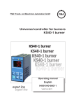
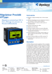
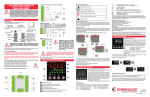
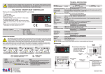
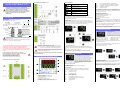
KS 20-1/PRO-16 INDUSTRIAL CONTROLLER
CONCISE PRODUCT MANUAL 59533-1
Universal Input 1 and Digital Inputs 1 & 2:
Status LED Indicators
Manual mode is active
Timer or profiler is active
CAUTION: Installation should be only performed by
technically competent personnel. Local Regulations
regarding electrical installation & safety must be observed.
The host equipment is required to provide a suitable
electrical, mechanical and fire enclosure to meet relevant
safety standards. Impairment of protection will occur if the
product is used in a manner not specified by the
manufacturer.
Setpoint SP.2 or SP.E is in use
Heat / valve open output is active
Cool / valve close output is active
Alarm is active
1. INSTALLATION
Panel-Mounting
The mounting panel must be rigid, and may be up to
6.0mm (0.25inch) thick. Cut-out sizes:
Options 1, 2 and 3:
Operator screens
In operator mode the unit displays the key screens for controller operation. Two
screens for the controller (PV with setpoint or output value) and one for the profiler (if
configured). The operating level can be expanded with an “Extended operating level”
Furthermore the user can access the “function level” with the F-key.
B
Cut-out Dim A
/16 DIN = 45mm
1
Cut-out Dim B
/16 DIN = 45mm
1
For n multiple instruments mounted side-by-side, cut-out
A is 48n-4mm.
Behaviour after power-on
After the supply voltage is switched-on, the unit starts in the operator mode.
The unit will be in the condition in which it was before power-off.
If the controller was in manual mode before power-off, the controller starts with the
last output value before power-off.
A
Tolerance +0.5, -0.0mm
Loc
rem
Local-operation adjustment via front-panel possible
Remote-operation adjustment via front-panel not possible
blc.P
blc.C
u.blc
Configuration-, parameter and calibration-level blocked
Configuration-level blocked
All blocking cancelled
After opening the list the display will show the actual setting of the first section.
Use the ENTER key to scroll to the next section and UP/DOWN-Keys to select
functions. To activate the selected setting press ENTER or just wait 2 seconds before
proceeding to the next screen.
Example: Select setpoint SP.2
Press the F-key (display will show Err)
Press ENTER until you see SP, SP.E or SP.2
Select SP.2 with the UP/DOWN-Keys
Press ENTER to activate
Press the F-key to leave the function level
Self-tuning
If the permissions in the configuration menu allow, self-tuning can be initiated by
simultaneously pressing the UP and ENTER key. The lower display line will toggle
between the setpoint and the self-tuning state. Press the same keys to abort an
active self-tuning.
Please refer to the full manual to learn about the meaning of the state messages and
see the different optimization methodologies available.
See the full user manual for details. Download at:
http://www.west-cs.com/products/models/pro-16-single-loop-controller
1. Insert instrument into
the panel cut-out.
Mounting Panel
Instrument
Housing
Ratchets
Gasket
2. Hold front bezel firmly
(without pressing on
display area), and re-fit
mounting clamp. Push
clamp forward, using a
tool if necessary, until
gasket is compressed
and instrument held firmly
in position.
4. PROFILER OPERATION
Operating the Profiler
The F-key opens the profiler control menu in the
lower display line. The display will show “P:”
followed by the actual state. Depending on the
configuration, the menu allows the user to select
run/stop or run/stop/reset with the UP/DOWN-keys.
Press ENTER to make the selected state active.
Option A:
CAUTION: For an effective IP65 seal against dust and moisture, ensure
gasket is well compressed against the panel, with the 4 tongues located in
the same ratchet slot.
OFF
Stop
run
It is essential that the controller is installed with a minimum of 20mm of free space
around the case in order to allow adequate ventilation.
Stop program execution and reset
Stop program execution
Start program execution
The profiler start screen is shown above. The upper display line shows the program
or segment execution time.
The lower line shows the program-number or segment-number and the state of the
profiler. Details for both lines can be configured.
Rear Terminal Wiring
All connections to the device must be made through a spade format or similar
connection, with connection to the spade terminal touching both the
insulation and conductor material. (Use a standard crimping tool).
All connections must be mechanically secured so as to prevent any wiring
becoming loose and coming in contact with other wires or the instrument
casing.
The above applies to any and all connection to hazardous
mains supply either direct or indirect (through a switch or relay)
Use copper conductors (except for T/C Inputs)
Use Screened Cable on Retransmission Options
Single Strand wire gauge: Max 1.2mm (18 SWG)
Cabling must have a minimum temperature rating of 80 deg C.
CAUTION: Check information label on housing for correct operating
voltage before connecting supply to Power Input
Fuse: 100 – 240V ac – 1A anti-surge 10A breaking capacity at 250V
24V ac/dc – 315mA anti-surge 3.5A breaking capacity at 48V
Electrical shock can result in death or serious injury. Avoid contact
with the leads and terminals. High voltages that may be present on
leads can cause electrical shock
Note: At first power-up please check that settings of input and output usage fit
to your needs and wiring.
The content of the extended operating level and the function level is based on
configurations made with the configuration utility BlueControl. Parameters used
frequently or important measured values can be placed into the extended operating
level.
See the full user manual for details. Download at:
http://www.west-cs.com/products/models/pro-16-single-loop-controller
3. CONTROLLER OPERATION
This is the start screen in controller mode.
The upper display line always shows the process
value. The lower line is used for the setpoint.
2. FRONT PANEL AND OPERATION BASICS
A second screen shows the output value in the lower
line. The status line has six LED beacons which
indicate the following (left to right): controller in
manual operation, timer or program is active,
alternative setpoint used, heat mode active or valve
open, cool mode active or valve close and limit
alarm active.
Assignment of connectors to options modules:
Changing the setpoint
The setpoint can be adjusted by pressing the UP/DOWN-keys.
Control Functions
The F-key opens the function list in the lower display line. Depending on
configurations (LOGI) the list contains the following groups of parameters:
1. Process value display
2. Set-point, controller output or parameter
3. Status LED indicators – see next column
4. Ramp gradient is active
5. F-key to alter or activate functions
6. UP/DOWN to change set-point or controller output value
7. ENTER to accept value and show next screen
Screen sequence shown below:
Err
Ereset
No reset of the error list
Resetting the error list
SP
SP.E
SP.2
Internal setpoint active
External setpoint active
Second setpoint active
On
Off
Controller/Signaler and Limit 1 are active
Controller/Signaler and Limit 1 are switched off
Auto
Man
Automatic operation
Manual operation
Program/segment selection
Prerequisite: Programmer is in the reset or stop condition and program / segment
selection (Pr.no / Pr.SG) is set in the extended operating level.
The procedure to select a defined program (Pr.no) followed by a segment (Pr.SG) is
shown below. When starting the programmer now, program operation starts at the
beginning of the selected segment in the selected program.
Lim:
End:
End of Program
The last setpoint remains active
Search run at programmer start
The programmer starts the first segment at the actual process value (search run).
This may change the effective runtime of the first segment.
See the full user manual for details. Download at:
http://www.west-cs.com/products/models/pro-16-single-loop-controller
5. ALARM MESSAGES
In case of an alarm the lower display line will toggle between red and green and an
alarm screen will be added to the list of operator screens. Navigate to the alarm
screen by pressing the ENTER-key. You will find one of the following messages:
Alarm
Fbf.1/2/3
General Profiler Overview
Programs
Control outputs
Segments
Segment types
Time units
Maximum segment duration
Maximum program duration
Gradient
Program name
Bandwidth control
16
4
16 per program
ramp (set-point and time)
ramp (set-point andv gradient)
hold segment (holding time)
step segment (with alarm suppression)
end segment
All segment types can be combined
with ”Wait at the end and call operator”
configurable in hours:minutes or
minutes:seconds
9999 hours = 1 year 51 days
16 x 9999 hours = > 18 years
0.01°C/h ( /min) to 9999°C/h ( /min)
8 characters, adjustable via
BlueControl software
bandwidth high and low (b.Lo,b.Hi)
limits definable for each program
Description
Feedback failure
Input 1/2/3
Sht.1/2/3 Short circuit
Input 1/2/3
POL.1/3
polarity reversal
Input 1/3
HCA
Heater current
alarm
SSr
Solid state relay
LooP
Loop alarm
AdA.H
Adaption Heat
Ada.C
Adaption Cool
Lim. 1/2/3 Limit alarm
Inf.1
Info service
interval
(life time counter)
Inf.2
Info service
interval
(relay cycle
counter)
E.1
Hardware problem
E.2
Internal problem
E.4
Option module
problem
Corrective Action
Check sensor and wiring
Check input wiring
Check input wiring
Contains alarm limits
When in a sub-section, the display will toggle between the parameter name and its
value. Use the UP/DOWN-keys to change settings and ENTER to move to the next
parameter. When at the end of a sub-section the display will show “done” and then
the next sub-section name. At the end of the sub-section list the display will show
“End” and return to the operator level.
See the full user manual for details. Download at:
http://www.west-cs.com/products/models/pro-16-single-loop-controller
Note: It is highly recommended that the controller is used in conjunction with
the BlueControl configuration utility. This will increase ease of use, save setup time and help prevent controller malfunction.
A demonstration version of the BlueControl configuration utility is available as a free
download from http://www.west-cs.com. The full “Expert” version is available to
purchase from your local dealer.
7. SPECIFICATION
INPUTS
Check heating element and wiring
Check SSR and output circuit
Check fuses, heaters and wiring
refer to auto tuning section in full manual
refer to auto tuning section in full manual
Check process
Contact repair department /service centre
Check for EMC issues
Try power on reset
Check option module fitting or contact repair
department /service centre
6. SETUP AND CALIBRATION
After power-up, the controller will show the operating level in the lower level text line.
The controller status is retained and will be the same as before the last power-down.
To access the options for parameter set-up, configuration and calibration, press
ENTER for more than 3 seconds.
This will now allow the options to be accessed: Use the UP/DOWN-keys to select
the option and ENTER to go to the next option.
Process Value Input INP1
Resolution:
> 14 bit
Decimal point:
0 to 3 decimal places
Digital input filter:
adjustable 0.000...9999 s
Scanning cycle:
100 ms
Measured value
correction:
2-point or offset correction
Thermocouples
Input impedance:
1 MΩ
Effect of source
resistance:
1 V/Ω
Thermocouple types: B, C, D, E, J, K, L, N, R, S, T
Resistance thermometer: PT100, PT1000, KTY 11-6
Cold junction compensation
Max. additional error: < 0.5 K
Sensor break monitoring
Sensor current:
≤ 1 µA
Operating sense configurable
Resistance thermometer
Connection:
3-wire
Lead resistance:
max. 30Ω
Input circuit monitor: Break and short circuit
Current and voltage signals
Span start, end of span: anywhere within measuring range
Scaling:
Selectable -1999...9999
Linearization:
16 segments, configurable with BlueControl
Decimal point:
adjustable
Input circuit monitor: 12.5% below span start (2mA, 1V)
Resolution:
> 14 bit
Scanning cycle:
100 ms
Accuracy:
Better than 0.1%
Heating current measurement via current transformer
Measuring range:
0...30mA AC
Scaling:
adjustable -1999..0,000..9999 A
Accuracy:
0.25%
Remote setpoint measurement range
Input resistance:
approx. 120Ω
Span:
configurable within 0 to 20mA
Scaling:
adjustable -1999...9999
Input circuit monitor: 12.5% below span start (4..20mA 2mA)
CONTROL INPUT DI1 & DI2
Examples of profiler displays:
Profiler OFF.
Program 01 selected
Internal controller setpoint is active
Profiler in run mode
Program 02 or Segment 02 active
Setpoint is ramping up “/”
Sections:
PROG: This is used to edit programs for the profiler.
PARA: This allows access to the two sets of PID parameters, setpoint limits,
scaling of input signals, alarm limits and the program selection.
.
CONF: Used to select the controller function, activate the profiler, to set input
types, to choose alarm functions, to assign functions to outputs and to configure
the user interface.
CAL:
This section is used for calibration of the process inputs.
After choosing a section the display will show the first option of the sub-section. Use
the same procedure to choose and enter the desired sub-section.
Sub-sections: (for example PARA)
Cntr:
Contains PID parameters.
Par.2: Contains a second set of PID parameters.
Setp:
Contains setpoint limits
Inp.1: Contains scaling and input filter
Inp.2: Contains scaling
Configurable as direct or inverse switch or push-button.
Connection of a potential-free contact suitable for switching “dry“ circuits.
Switched voltage:
3.3V
Switched current:
< 10mA
CONTROL INPUTS DI3 & DI4
(OPTIONAL)
These inputs (if ordered) are in the option A position and are configurable as direct
or inverse.
Nominal voltage:
24 V DC, external current sink (IEC 1131 Type 1)
Logic “0”:
-3...+5V
Logic “1”:
+15...+30V
Current requirement: approx. 5mA
OUTPUTS
Relay – option 1-3
Contacts:
Max contact rating:
Min contact rating:
Duty cycle:
Potential free changeover
2A@ 250V 48…62Hz
6V, 1mA
I = 1A/2A, 250,000/150,000 operations @ 250V
resistive
Dual relay – option 2
Contacts:
2 NO contacts with
shared common
Max contact rating:
2A@ 250V 48…62Hz
Min contact rating:
6V, 1mA
Duty cycle:
I = 1A/2A, 500,000/200,000 operations @ 250V resistive
SSR - option 1-3
Voltage:
10V into 500Ω minimum
Dual SSR - option 1-3
Voltage:
10V into 500Ω minimum
Linear DC output option 1 & 3
(1) Current output
0/4mA...20 mA, configurable.
Signal range:
0...approx. 22mA
Load:
≤ 500 Ω
Load effect:
none
Resolution:
(0.1%)
Error:
(0.2%)
(2)
Voltage output
0-10 V
Signal range:
Load:
Resolution:
Error:
0...11 V
≥ 2KΩ
≤ 0.1 %
≤ 0.2 %
Bus interface - option 3 or option A
Physical:
RS485, at 1200, 2400, 4800, 9600 or 19200 bps.
Protocol:
Modbus RTU Communications
Transmitter power supply
Output:
22 mA / ≥ 18 V
8. ENVIRONMENTAL
Operating Conditions (For indoor use)
Ambient
0°C to 60°C (Operating), –20°C to 70°C (Storage).
Temperature:
Relative Humidity: 75% yearly average no condensation
Supply Voltage and 100 to 240V AC ±10%, 50/60Hz, 11.5VA (mains voltage input
Power:
version)
24V AC ±10%, 50/60Hz, 11.5VA or 24V DC ±10%, 10W (low
voltage input version)
Certification
Standards:
EMI:
CE, UL, cUL
Complies with EN61326 (Susceptibility & Emissions).
Complies with EN61010-1
Safety
Pollution Degree 2, Installation Category II.
Considerations:
Front Panel Sealing: To IP65 (IP20 behind the panel).
Physical
1
/16 DIN = 48 x 48mm.
Front Bezel Size:
Depth Behind Panel: 110mm.
Weight:
0.21 Kg maximum.
Cleaning
If cleaning is necessary, the front panel should be cleaned by washing with warm
soapy water and drying immediately using a dry, lint free cloth.
Manufacturing site
Address:
The Hyde Business Park
Brighton
BN2 4JU
United Kingdom
Full user documentation
More comprehensive user documentation is available in the full user manual which
is available to download at:
http://www.west-cs.com/products/models/pro-16-single-loop-controller
Symbol Explanation
Caution: general danger to life or limb