1
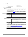
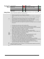
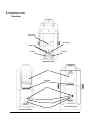
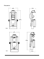
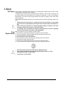
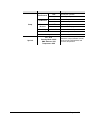
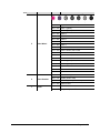
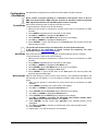
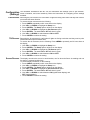
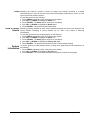
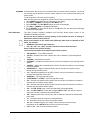
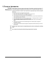
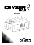
User Manual
TABLE OF CONTENTS
1. Before You Begin ................................................................................................................ 4
What is Included .................................................................................................................................................. 4
Unpacking Instructions ......................................................................................................................................... 4
Claims .................................................................................................................................................................. 4
Text Conventions ................................................................................................................................................. 4
Symbols ............................................................................................................................................................... 4
Disclaimer ............................................................................................................................................................ 4
Product at a Glance ............................................................................................................................................. 5
Safety Notes ........................................................................................................................................................ 5
2. Introduction ......................................................................................................................... 6
Overview .............................................................................................................................................................. 6
Dimensions .......................................................................................................................................................... 7
3. Setup .................................................................................................................................... 8
AC Power ............................................................................................................................................................. 8
Fuse Replacement ............................................................................................................................................... 8
Power Linking ...................................................................................................................................................... 9
Power Linking Diagram................................................................................................................................... 9
Mounting ............................................................................................................................................................10
Orientation .........................................................................................................................................................10
Rigging ...............................................................................................................................................................10
Rigging Diagram ...........................................................................................................................................10
4. Operation ........................................................................................................................... 11
Control Panel Description ..................................................................................................................................11
Menu Map .....................................................................................................................................................11
Configuration (DMX) ..........................................................................................................................................13
DMX Starting Address ..................................................................................................................................13
DMX Personalities ........................................................................................................................................13
DMX Channel Assignments and Values.......................................................................................................14
11-CH .................................................................................................................................................................... 14
7CH ........................................................................................................................................................................ 17
Configuration (Standalone) ................................................................................................................................19
Sound Mode .................................................................................................................................................19
Auto Mode ....................................................................................................................................................19
Manual Mode ................................................................................................................................................19
Configuration (Settings) .....................................................................................................................................20
Pan Reverse .................................................................................................................................................20
Tilt Reverse ...................................................................................................................................................20
Screen Reverse ............................................................................................................................................20
Reset.............................................................................................................................................................21
Reset to Factory Defaults .............................................................................................................................21
System Information ............................................................................................................................................21
IR Mode ........................................................................................................................................................22
IRC-6 Operation ................................................................................................................................................... 22
Configuration (Master/Slave) .............................................................................................................................23
Configuring the Slaves..................................................................................................................................23
Configuring the Master .................................................................................................................................23
5. Technical Information ....................................................................................................... 24
Intimidator Scan/Barrel 305 IRC User Manual Rev. 1
Page 2 of 27
Product Maintenance .........................................................................................................................................24
6. Technical Specifications .................................................................................................. 25
Returns................................................................................................................................... 26
Contact Us ............................................................................................................................. 27
Intimidator Scan/Barrel 305 IRC User Manual Rev. 1
Page 3 of 27
1. BEFORE YOU BEGIN
What is
Included
Unpacking
Instructions
Claims
Text
Conventions
·
·
Power Cord
Warranty Card
Quick Reference Guide
Carefully unpack the product immediately and check that all the parts are in the package and
are in good condition.
If the box or any of the contents appear damaged from shipping, or show signs of mishandling,
save all packaging and file a claim with the carrier immediately, do not notify Chauvet. Failure
to report damage to the carrier immediately or failure to have all packaging available for
inspection may invalidate your claim.
For other issues, such as missing components or parts, damage not related to shipping, or
concealed damage, file a claim with Chauvet within 7 days of delivery. For information on
contacting Chauvet, see the Contact Us section of this manual.
Convention
Meaning
1–512
A range of values
50/60
A set of values
Settings
A menu option
Menu > Settings
<ENTER>
ON
Symbols
·
·
·
Intimidator Scan 305 IRC
or
Intimidator Barrel 305 IRC
A sequence of menu options
A button to be pressed
A value to be entered or selected
Symbol
Meaning
Critical installation, configuration, or operation information. Not following
these instructions can make the product not work, cause damage to the
product, or cause harm to the operator.
Important installation or configuration information. The product might
not function correctly if this information is not used.
Useful information.
Disclaimer
The information and specifications contained in this User Manual are subject to change without
notice. Chauvet assumes no responsibility or liability for any errors or omissions, and reserves
the right to revise or recreate this manual at any time. The latest version of this manual should
be downloaded from http://www.chauvetlighting.com/product-manuals-literature/.
© Copyright 2015 Chauvet. All rights reserved.
Electronically published by Chauvet in the United States of America.
Author
Date
Editor
Date
M. Trouard
11/03/15
M. Gregory
11/03/15
Intimidator Scan/Barrel 305 IRC User Manual Rev. 1
Page 4 of 27
Product at a
Glance
Use on Dimmer
Outdoor Use
Sound-Activated
DMX
Master/Slave
Safety Notes
x
x
P
P
P
Auto Programs
Auto-ranging Power Supply
Replaceable Fuse
User-Serviceable
P
P
P
x
These notes include important information about the mounting, use, and maintenance of this
product. Read these notes before using the product.
·
·
·
·
·
·
·
·
·
·
·
·
·
·
·
·
·
·
·
·
·
·
Always connect the product to a grounded circuit to avoid the risk of electrocution.
Make sure the power cord is not crimped or damaged.
Always disconnect the product from the power source before cleaning it or replacing the
fuse.
Never disconnect the product from the power source by pulling or tugging on the cord.
If mounting the product overhead, always secure it using a safety cable.
Make sure there are no flammable materials close to the product when it is operating.
Avoid direct eye exposure to the light source while the product is on.
Do not touch the product’s housing when the product is operating because the housing can
be very hot.
This product is not intended for permanent installation.
The product is for indoor use only! It is rated at IP20.
To prevent risk of fire or shock, do not expose the product to rain or moisture.
Always make sure that the voltage of the power source to which the product is connected
is within the range stated on the sticker or rear panel of the product.
Never connect the product to a dimmer or rheostat.
Make sure to replace the fuse with another of the same type and rating.
Always install the product in a location with adequate ventilation, and leave at least 20 in
(50 cm) between the product and adjacent surfaces.
Always use the handles to carry this product.
The maximum ambient temperature (Ta) in which the product can be used is
104 °F (40 °C). Do not operate the product at higher temperatures.
Be sure that no ventilation slots on the product’s housing are blocked.
Never carry the product by the power cord or any moving part.
In the event of a serious operating problem, stop using the product immediately.
Never try to repair the product. Repairs carried out by unskilled people can lead to damage
or malfunction. Contact the nearest authorized technical assistance center.
To eliminate wear and improve its lifespan, during periods of non-use completely
disconnect from power via breaker or by unplugging it.
Keep this User Manual for future reference. If you sell the product to another user, be sure to
give this manual to the next owner.
Intimidator Scan/Barrel 305 IRC User Manual Rev. 1
Page 5 of 27
2. INTRODUCTION
Overview
Safety Cable
Pass-Through
Fuse Holder
DMX In/Out
Power Out
Power In
Back Panel View
Mirror
Adjustable
Lens
Display
IR Sensor
LED Indicator
Menu Buttons
Front View (Scan)
Front View (Barrel)
Intimidator Scan/Barrel 305 IRC User Manual Rev. 1
Page 6 of 27
Dimensions
10 in
255 mm
6.7 in
171 mm
18.9 in
480 mm
Barrel
10 in
255 mm
16.9 in
430 mm
Scan
Intimidator Scan/Barrel 305 IRC User Manual Rev. 1
5.7 in
147 mm
Page 7 of 27
3. SETUP
AC Power
The Intimidator Scan/Barrel 305 IRC have auto-ranging power supplies that work with an input
voltage range of 100 to 240 VAC, 50/60 Hz.
To determine the product’s power requirements (circuit breaker, power outlet, and wiring), use
the values listed on the label affixed to the product’s back panel, or refer to the product’s
Specifications. The listed current rating indicates the product’s average current draw under
normal conditions.
The Intimidator Scan/Barrel 305 IRC can be power linked via the IEC and Edison outlets in its
base.
·
·
·
Fuse
Replacement
Always connect the product to a protected circuit (circuit breaker or fuse). Make
sure circuit has an appropriate electrical ground to avoid the risk of electrocution or
fire.
Never connect the product to a rheostat (variable resistor) or dimmer, even if the
rheostat or dimmer serves only as a 0 to 100% switch.
To eliminate wear and improve its lifespan, during periods of non-use completely
disconnect from power via breaker or by unplugging it.
Make sure product is not connected to a power source.
1. Place the tip of a flat-head screwdriver into the slot in the fuse holder.
2. Turn the screwdriver counterclockwise and the fuse holder will come loose.
3. Pull the fuse holder out of the product.
4. Pull the blown fuse out of the fuse holder.
5. Place a new fuse of the exact same type and rating into the fuse holder.
6. Insert the fuse holder into the product.
7. Place the tip of a flat-head screwdriver into the slot in the fuse holder.
8. Turn the screwdriver clockwise and the fuse holder will tighten into place.
·
·
·
Disconnect the product from power before replacing the fuse.
Use only the fuse listed in the Technical Specifications section or on the
specifications sticker on the product.
A spare fuse is not included.
Intimidator Scan/Barrel 305 IRC User Manual Rev. 1
Page 8 of 27
Power Linking
The product provides power linking via the Edison/IEC outlet located in the back of the unit.
Power Linking
Diagram
st
1
Product
nd
2
Product
rd
3
Product
Additional Products
Up to 5 Intimidator Scan/Barrel 305 IRC units can be linked on 120 V, or up to
12 Intimidator Scan/Barrel 305 IRC units on 230 V.
·
·
The power linking diagram shown above corresponds to the North American version
of the product ONLY!
If using this product anywhere other than North America, consult with the local
Chauvet distributor because power linking connectors and requirements differ from
country to country, and region to region.
Intimidator Scan/Barrel 305 IRC User Manual Rev. 1
Page 9 of 27
Mounting
Before mounting the product, read and follow the safety recommendations in the Safety Notes
section.
Orientation
The Intimidator Scan/Barrel 305 IRC can be mounted in any position, but make sure the
placement allows adequate ventilation for the product, and allows for movement of the yoke
and head in any direction.
Rigging
Be sure to place the product in a location that allows easy access to it for maintenance and
programming, and enough space around the product for ventilation.
Make sure that the structure or surface onto which the product will be mounted can support the
product’s weight. For more information see the Technical Specifications section.
When mounting the product overhead, always use a safety cable and make sure the product is
attached securely.
When mounting the product on a truss or pipe, use a mounting clamp with the appropriate
weight
capacity.
Chauvet
has
a
full
range
of
mounting
clamps.
See
http://www.chauvetlighting.com/cables-clamps-main.html for the complete selection.
The rubber feet serve as floor supports. When placing the product on the floor, make sure that
the product and cables are away from people and vehicles.
Mounting Clamps
(such as CLP-15 from Chauvet)
Rigging Diagram
Hanging/
Mounting
Bracket
Safety Cable
(such as CH-05 from
Chauvet)
Secure the safety cable
using the pass-through on
the back of the product
Rubber Feet (x4)
Intimidator Scan/Barrel 305 IRC User Manual Rev. 1
Page 10 of 27
4. OPERATION
Control Panel
Description
The control panel is used to set the operating mode, and the configuration settings of the
product. Use the 4 buttons underneath the LCD display to access the control panel and
navigate the menu map. For specific instructions see the Configurations sections below.
Button
Function
<MENU>
Enters into, or backs out of, the current menu option
<UP>
Scrolls up the list of options or selects a higher value
<DOWN>
Scrolls down the list of options or selects a lower value
<ENTER>
Activates a selected menu or value
Menu Map The Menu Map presents all the options in the menu system, and the values to set them.
Menu
Value
Description
Address
001–512
Sets the DMX starting address
7CH
DMX
11CH
Slave
Slave1–4
Auto
Sets Sound mode
IR
Sets infrared control
Pan
0 to 180°
Tilt
0 to 90°
P/T Speed
Pan/Tilt speed (fast to slow)
Color
Selects color options
Dimmer
Sets dimmer value
Shutter
Manual
Intimidator Scan/Barrel 305 IRC User Manual Rev. 1
Sets Slave mode
Sets Auto mode
Sound
Run Mode
Sets DMX personality
Gobo
Strobe effect with increasing speed
000–255
Selects Gobo options
Gobo
Rotate
Rotation
speed
Prism
Selects 3-facet prism
effect
with
increasing
Special
Function
Selects control functions
P/T Macro
Selects pan/tilt movement macros
Page 11 of 27
Menu
Value
OFF
Normal pan operation
ON
Reverse pan operation
OFF
Normal tilt operation
ON
Reverse tilt operation
Screen
Reverse
OFF
Normal display
ON
Upside-down display
Sensitivity
001—100
Sets sound sensitivity
Pan Reverse
Tilt Reverse
Setup
Description
Reset
Factory Set
Sys Info
Ver: VX.X
Running Mode: XXXX
DMX Address: XXX
Temperature: XXX
Intimidator Scan/Barrel 305 IRC User Manual Rev. 1
Resets the product
Loads factory defaults
Shows the current software version,
running mode, DMX address and
product’s temperature
Page 12 of 27
Configuration
(DMX)
To set the product in DMX mode for control with a DMX controller, do the following:
1. Make sure the product is plugged into a power source.
2. Connect the male end of a DMX cable to the DMX out socket of the DMX controller and
the female end of the same cable to the DMX in socket on the product.
3. Set the DMX starting address and personality by following the directions below.
DMX Starting When selecting a starting DMX address, always consider the number of DMX channels
Address needed for the selected DMX personality. Choosing a starting address that is too high can
restrict access to some of the product’s channels.
The Intimidator Scan/Barrel 305 IRC uses either 7 or 11 channels, depending on the
personality. The highest configurable DMX address in 7-channel mode is 506. The highest
configurable DMX address in 11-channel mode is 502.
For more information about DMX download the Chauvet DMX Primer from the Chauvet web
site http://www.chauvetlighting.com/download.
To set the DMX starting address, do the following:
1. If the display shows a number from 001–512, go to step 5.
2. Press <MENU> repeatedly until 4 icons show on the display.
3. Use <UP> or <DOWN> to highlight Address.
4. Press <ENTER> and a number from 001–512 will show on the display.
5. Use <UP> or <DOWN> to change the number to the desired DMX starting address.
6. Press <ENTER> to select the DMX starting address.
DMX Personalities The Intimidator Scan/Barrel 305 IRC has 2 DMX personalities: a 7-channel personality and
an 11-channel personality.
To set the DMX personality, do the following:
1. Press <MENU> repeatedly until 4 icons show on the display.
2. Use <UP> or <DOWN> to highlight the Run Mode icon.
3. Press <ENTER> and the Run Mode options will show on the display.
4. Use <UP> or <DOWN> to highlight DMX.
5. Press <ENTER>. A green dot will show on the DMX option line and the characters 7CH
or 11CH will show in green.
6. Use <UP> or <DOWN> to switch between 7CH and 11CH.
7. Press <ENTER> to select the DMX personality shown.
After the DMX starting address and personality have been set, there will be a delay of
30 seconds before the display automatically returns to showing the current DMX
address and the DMX personality.
Intimidator Scan/Barrel 305 IRC User Manual Rev. 1
Page 13 of 27
DMX Channel The following table outlines all the capabilities of the Intimidator Scan/ Barrel 305 IRC and
Assignments and the channels that control them when the light is used with a lighting controller.
Values
11-CH
Channel
1
Function
Value
Percent/Setting
Pan
000 ó 255 0–180°
Tilt (Scan)
000 ó 255 0–90°
000 ó 019 Stop
2
Tilt (Barrel)
020 ó 135 Clockwise rotation (slow to fast)
136 ó 139 Stop
140 ó 255 Counter-clockwise rotation (slow to fast)
3
Pan/Tilt Speed
000 ó 255 Fast to slow
000 ó 006 Open (white)
007 ó 013 Yellow
014 ó 020 Purple
021 ó 027 Green
028 ó 034 Red
035 ó 041 Light Blue
042 ó 048 Kelly Green
049 ó 055 Orange
056 ó 063 Dark Blue
4
Color
064 ó 070 White + Yellow (split colors)
071 ó 077 Yellow + Purple (split colors)
078 ó 084 Purple + Green (split colors)
085 ó 091 Green + Red (split colors)
092 ó 098 Red + Blue (split colors)
099 ó 105 Light Blue + Kelly Green (split colors)
106 ó 112 Kelly Green + Orange (split colors)
113 ó 119 Orange + Dark Blue (split colors)
120 ó 127 Dark Blue + White (split colors)
128 ó 191 Rotate counter-clockwise (slow to fast)
192 ó 255 Rotate clockwise (slow to fast)
000 ó 003 Closed
004 ó 007 Open
5
Shutter
008 ó 076 Synchronized Strobe (slow to fast)
077 ó 145 Pulse Strobe (slow to fast)
146 ó 215 Random Strobe (slow to fast)
216 ó 255 Open
Intimidator Scan/Barrel 305 IRC User Manual Rev. 1
Page 14 of 27
11-CH
Channel
6
Function
Dimmer
Value
Percent/Setting
000 ó 255 0 to 100%
000 ó 007 Open
008 ó 015 Gobo 1 (glass)
016 ó 023 Gobo 2 (glass)
024 ó 031 Gobo 3
032 ó 039 Gobo 4
040 ó 047 Gobo 5
048 ó 055 Gobo 6
7
Gobo Wheel
056 ó 063 Gobo 7
064 ó 071 Gobo 7 shake, fast to slow
072 ó 079 Gobo 6 shake, fast to slow
080 ó 087 Gobo 5 shake, fast to slow
088 ó 095 Gobo 4 shake, fast to slow
096 ó 103 Gobo 3 shake, fast to slow
104 ó 111 Gobo 2 (glass) shake, fast to slow
112 ó 119 Gobo 1 (glass) shake, fast to slow
120 ó 127 Open
128 ó 191 Gobo scroll: counter-clockwise rotation
192 ó 255 Gobo scroll: clockwise rotation
000 ó 063 Gobo indexing counter-clockwise
8
Gobo Rotation
064 ó 147 Rotate (slow to fast)
148 ó 231 Rotate opposite (slow to fast)
232 ó 255 Gobo bounce
9
Prism
Intimidator Scan/Barrel 305 IRC User Manual Rev. 1
000 ó 007 Prism
008 ó 255 Stop, static prism effect
Page 15 of 27
11-CH
Channel
Function
Value
Percent/Setting
000 ó 007 No function
008 ó 015 Pan/tilt move-in-black
016 ó 023 Pan/tilt move-in-black (disable)
024 ó 031 Color wheel move-in-black
032 ó 039 Gobo wheel move-in-black (disable)
040 ó 047 Gobo wheel move-in-black
048 ó 055
Color wheel and Gobo wheel move-in-black
(disable)
056 ó 063 Fast movement
064 ó 087 Fast movement (disable)
10
Operating Mode
088 ó 095 All movement move-in-black (disable)
096 ó 103 Reset pan/tilt
104 ó 111 No function
112 ó 119 Reset color wheel
120 ó 127 Reset gobo wheel
128 ó 135 No function
136 ó 143 Reset prism
144 ó 151 No function
152 ó 159 Reset all
160 ó 255 No function
000 ó 007 No function
008 ó 023 Automatic 1
024 ó 039 Automatic 2
040 ó 055 Automatic 3
056 ó 071 Automatic 4
072 ó 087 Automatic 5
088 ó 103 Automatic 6
104 ó 119 Automatic 7
11
Movement
Macros
120 ó 135 Automatic 8
136 ó 151 Sound 1
152 ó 167 Sound 2
168 ó 183 Sound 3
184 ó 199 Sound 4
200 ó 215 Sound 5
216 ó 231 Sound 6
232 ó 247 Sound 7
248 ó 255 Sound 8
Intimidator Scan/Barrel 305 IRC User Manual Rev. 1
Page 16 of 27
7CH
Channel
1
Function
Value
Pan
000 ó 255 0 to 180°
Tilt (Scan)
000 ó 255 0 to 90°
Percent/Setting
000 ó 019 Stop
2
Tilt (Barrel)
020 ó 135 Clockwise rotation (slow to fast)
136 ó 139 Stop
140 ó 255 Counter-clockwise rotation (slow to fast)
000 ó 006 Open (white)
007 ó 013 Yellow
014 ó 020 Purple
021 ó 027 Green
028 ó 034 Red
035 ó 041 Light Blue
042 ó 048 Kelly Green
049 ó 055 Orange
056 ó 063 Dark Blue
3
Color
064 ó 070 White + Yellow (split colors)
071 ó 077 Yellow + Purple (split colors)
078 ó 084 Purple + Green (split colors)
085 ó 091 Green + Red (split colors)
092 ó 098 Red + Blue (split colors)
099 ó 105 Light Blue + Kelly Green (split colors)
106 ó 112 Kelly Green + Orange (split colors)
113 ó 119 Orange + Dark Blue (split colors)
120 ó 127 Dark Blue + White (split colors)
128 ó 191 Rotate counter-clockwise (slow to fast)
192 ó 127 Rotate clockwise (slow to fast)
000 ó 003 Closed
004 ó 007 Open
4
Shutter
008 ó 076 Synchronized Strobe (slow to fast)
077 ó 145 Pulse Strobe (slow to fast)
146 ó 215 Random Strobe (slow to fast)
216 ó 255 Open
Intimidator Scan/Barrel 305 IRC User Manual Rev. 1
Page 17 of 27
7CH
Channel
Function
Value
Percent/Setting
000 ó 007 Open
008 ó 015 Gobo 1 (glass)
016 ó 023 Gobo 2 (glass)
024 ó 031 Gobo 3
032 ó 039 Gobo 4
040 ó 047 Gobo 5
048 ó 055 Gobo 6
5
Gobo Wheel
056 ó 063 Gobo 7
064 ó 071 Gobo 7 shake, fast to slow
072 ó 079 Gobo 6 shake, fast to slow
080 ó 087 Gobo 5 shake, fast to slow
088 ó 095 Gobo 4 shake, fast to slow
096 ó 103 Gobo 3 shake, fast to slow
104 ó 111 Gobo 2 (glass) shake, fast to slow
112 ó 119 Gobo 1 (glass) shake, fast to slow
120 ó 127 Open
128 ó 191 Gobo scroll: counter-clockwise rotation
192 ó 255 Gobo scroll: clockwise rotation
000 ó 063 Gobo indexing
6
Gobo Rotation
064 ó 147 Rotate (slow to fast)
148 ó 231 Rotate opposite (slow to fast)
232 ó 255 Gobo bounce
7
Prism
Intimidator Scan/Barrel 305 IRC User Manual Rev. 1
000 ó 007 Prism
008 ó 255 Stop, static prism effect
Page 18 of 27
Configuration
(Standalone)
Use standalone configurations to operate the product without a DMX controller.
Never connect a product operating in a standalone mode (Sound, Auto, or IR) to a
DMX chain that includes a DMX controller. Products in standalone mode can transmit
DMX signals that interfere with the DMX signals from the controller
Sound Mode Sound mode sets the product to respond to sounds and music.
To set the product to Sound mode, do the following:
1. Make sure the product is connected to a power source and not connected to a DMX
controller.
2. Press <MENU> repeatedly until 4 icons show on the display.
3. Use <UP> or <DOWN> to highlight the Run Mode icon.
4. Press <ENTER> and the Run Mode options will show on the display.
5. Use <UP> or <DOWN> to highlight the Sound option.
6. Press <ENTER>. A green dot will show on the Sound option line and the product will
begin reacting to sound.
The product will respond only to low frequencies of music (bass and drums).
If the product is not responding to sound, increase the sensitivity. For more
information see the Sensitivity Setting below.
Auto Mode Auto mode sets the product to 1 of 16 preset movement patterns and color changes.
To set the product to Auto mode, do the following:
1. Make sure the product is connected to a power source and not connected to a DMX
controller.
2. Press <MENU> repeatedly until 4 icons show on the display.
3. Use <UP> or <DOWN> to highlight the Run Mode icon.
4. Press <ENTER> and the Run Mode options will show on the display.
5. Use <UP> or <DOWN> to highlight the Auto option.
6. Press <ENTER>. A green dot will show on the Auto option line and the product will
begin moving and emitting light.
Manual Mode Manual mode allows the user to control every function of the Intimidator Scan/Barrel 305
IRC through the LCD display. To run the product in Manual mode, follow the instructions
below:
1. Make sure the product is connected to a power source and not connected to a DMX
controller.
2. Press <MENU> repeatedly until 4 icons show on the display.
3. Use <UP> or <DOWN> to highlight the Run Mode icon.
4. Press <ENTER> and the Run Mode options will show on the display.
5. Use <UP> or <DOWN> to highlight the Manual option.
6. Press <ENTER> and the Manual options will show on the display.
7. Use <UP> or <DOWN> to select Pan, Tilt, P/T Speed, Color, Dimmer, Shutter, Gobo,
Gobo Rotate, Prism, Special Function, or P/T Macro.
8. Press <ENTER> and the current value (000–255) of the selected function will be
highlighted.
9. Use <UP> or <DOWN> to increase or decrease the value of the selected function.
10. Press <ENTER>.
11. Repeat steps 7–10 until the product is set as desired.
Intimidator Scan/Barrel 305 IRC User Manual Rev. 1
Page 19 of 27
Configuration
(Settings)
The Intimidator Scan/Barrel 305 IRC can be customized with settings such as pan direction,
screen orientation, and sound sensitivity. Below are instructions for configuring all the settings
available.
Pan Reverse Reversing the pan movement is useful when 2 lights are facing each other and they both need to
turn toward the same direction.
To reverse the pan movement do the following:
1. Press <MENU> repeatedly until 4 icons show on the display.
2. Use <UP> or <DOWN> to highlight the Setup icon.
3. Press <ENTER>. The Setup options will show on the display.
4. Use <UP> or <DOWN> to highlight the Pan Reverse option.
5. Press <ENTER>. The words ON or OFF will show in green.
6. Use <UP> or <DOWN> to switch between ON and OFF.
7. Press <ENTER> to select the setting.
Tilt Reverse Reversing the tilt movement is useful when 2 lights are facing each other and they need to point
towards the same space between them.
To reverse the tilt movement, do the following: Press <MENU> repeatedly until 4 icons show on
the display.
1. Use <UP> or <DOWN> to highlight the Setup icon.
2. Press <ENTER>. The Setup options will show on the display.
3. Use <UP> or <DOWN> to highlight the Tilt Reverse option.
4. Press <ENTER>. The words ON or OFF will show in green.
5. Use <UP> or <DOWN> to switch between ON and OFF.
6. Press <ENTER> to select the setting.
Screen Reverse The display can show the screen in two directions, one for when the fixture is standing and one
for when it is mounted upside-down.
To set the display orientation, do the following:
1. Press <MENU> repeatedly until 4 icons show on the display.
2. Use <UP> or <DOWN> to highlight the Setup icon.
3. Press <ENTER>. The Setup options will show on the display.
4. Use <UP> or <DOWN> to highlight the Screen Reverse option.
5. Press <ENTER>. The words ON or OFF will show in green.
6. Use <UP> or <DOWN> to switch between ON (upside-down display) and
OFF (normal display).
7. Press <ENTER> to select the setting.
Intimidator Scan/Barrel 305 IRC User Manual Rev. 1
Page 20 of 27
Reset Resetting will restart the product. It does not change any settings. Resetting is a helpful
troubleshooting tool, and can be used if the product has stopped responding to control, or if the
control system has suffered a failure.
To reset the product, do the following:
1. Press <MENU> repeatedly until 4 icons show on the display.
2. Use <UP> or <DOWN> to highlight the Setup icon.
3. Press <ENTER>. The Setup options will show on the display.
4. Use <UP> or <DOWN> to highlight the Reset option.
5. Press <ENTER>. The product will immediately reset.
Reset to Factory Resetting to factory defaults will clear out all customized settings and return thee settings to the
Defaults factory defaults. Resetting to factory defaults can be used if the product is behaving
inconsistently.
To reset the product to factory default settings, do the following:
1. Press <MENU> repeatedly until 4 icons show on the display.
2. Use <UP> or <DOWN> to highlight the Setup icon.
3. Press <ENTER>. The Setup options will show on the display.
4. Use <UP> or <DOWN> to highlight the Factory Set option.
5. Press <ENTER>. The product will immediately reset to factory default settings.
System
Information
To see the product’s current software version, running mode, DMX address and temperature, do
the following:
1. Press <MENU> repeatedly until 4 icons show on the display.
2. Use <UP> or <DOWN> to highlight the Sys Info icon.
3. Press <ENTER>. The current information about the product will show on the display.
Intimidator Scan/Barrel 305 IRC User Manual Rev. 1
Page 21 of 27
IR Mode IR mode allows the product to be controlled with an infrared remote controller. The IRC-6
can remotely set the product to various modes; adjust the color, speed and sensitivity; and
set the strobe.
To set the product to IR mode, do the following:
Make sure the product is plugged into a power source and not connected to a DMX cable.
1. Press <MENU> repeatedly until 4 icons show on the display.
2. Use <UP> or <DOWN> to highlight the Run Mode icon.
3. Press <ENTER>. The Run Mode options will show on the display.
4. Use <UP> or <DOWN> to highlight the IR option.
5. Press <ENTER>. A green dot will show on the IR option line and the product will begin
moving and emitting light.
IRC-6 Operation
The IRC-6 infrared controller (available from Chauvet) allows remote control of the
Intimidator Scan/Barrel 305 IRC.
Be sure the IRC-6 remote is pointing directly at the product and there is nothing in
between the remote and the product.
Some of the buttons on the remote work differently than what is indicated on their
labels. For example:
· <MANUAL> controls the gobo selection.
· <R>, <G>, <B>, <A>, <UV>, and <W> control the other manual functions.
Please read the next section carefully.
The list below describes which features each button controls.
· <BLACKOUT> - Turns LEDs on and off.
· <AUTO> - Activates Auto mode. Use the <+> and <-> buttons to cycle through Auto
modes.
· <SOUND> - Activates Sound mode.
· <STROBE> - Activates the strobe. Use the <+> and <-> buttons to cycle through strobe
speeds.
· <SPEED> - Adjusts the movement speed. Use the <+> and <-> buttons to cycle through
movement speeds.
· <SENSITIVITY> - Adjusts sound sensitivity. Use the <+> and <-> buttons to cycle
through sound sensitivity levels.
· <%> - Adjusts the brightness of the LEDs. Use the <+> and <-> buttons to increase or
decrease the brightness of the LEDs.
· <MANUAL> - Cycle through static gobos.
· <FADE/SNAP> or <FADE> - Cycle through static colors.
· <R> - Sets the color wheel rotation speed. Use the <+> and <-> buttons to increase or
decrease the color wheel rotation speed.
· <G> - Sets the gobo wheel rotation speed. Use the <+> and <-> buttons to increase or
decrease the gobo wheel rotation speed.
· <B> - Sets CG. AUTO mode. Colors and gobos will cycle automatically.
· <A> - Sets R/T PAN/TILT. Press <A> to toggle PAN and TILT. Use the <+> and <->
buttons to increase or decrease the selected value.
· <W> - Sets the prism value. Use the <+> and <-> buttons to increase or decrease the
prism value.
· <+> - Increases values for controls as described above.
· <-> - Decreases values for controls as described above.
· <0>–<9> - Activates specific Auto modes. Can be used as a shortcut for the
combination of the <AUTO> button and the <+> and <-> buttons.
· <UV> or <P> - Has no function with this product.
Intimidator Scan/Barrel 305 IRC User Manual Rev. 1
Page 22 of 27
Configuration
(Master/Slave)
Master/Slave mode allows a single Intimidator Scan/Barrel 305 IRC (the master) to control
the actions of one or more Intimidator Scan/Barrel 305 IRCs (the slaves) without a DMX
controller.
In Master/Slave mode the master is set to operate in Auto mode, Sound mode, or IR
mode and the slaves are set to operate in Slave mode.
The master and slaves are daisy chained though the DMX input and output ports with the
master at the beginning of the chain. Once set and connected, the slaves will operate
identically to, and in unison with, the master.
·
·
·
·
Always put the male DMX connector into the master. Do not connect to the
DMX In port on the master.
Never connect more than 31 slaves to the master.
Never connect a DMX controller to a DMX daisy chain of master and slaves.
Configure all the slaves before connecting the master to the DMX daisy chain.
Configuring the Configure the slaves for Slave mode before or after they are put in position, and before
Slaves they are daisy chained to the master.
To configure a slave, do the following:
1. Make sure the product is connected to a power source.
2. Press <MENU> repeatedly until 4 icons show on the display.
3. Use <UP> or <DOWN> to highlight the Run Mode icon.
4. Press <ENTER>. The Run Mode options will show on the display.
5. Use <UP> or <DOWN> to highlight the Slave option.
6. Press <ENTER>. The current Slave mode will be highlighted.
7. Use <UP> or <DOWN> to select the Slave mode.
· Select Slave1 for 100% synchronized actions.
· Select Slave2, Slave3, or Slave4 for a delayed show, creating a wave effect.
Configuring the Configure the master after all the slaves are connected to it and configured.
Master To configure the master, do the following:
1. Make sure the product is connected to a power source and connected to all of the
slaves.
2. Press <MENU> repeatedly until 4 icons show on the display.
3. Use <UP> or <DOWN> to highlight the Run Mode icon.
4. Select any of the Standalone modes as described in Configuration (Standalone).
Intimidator Scan/Barrel 305 IRC User Manual Rev. 1
Page 23 of 27
5. TECHNICAL INFORMATION
Product
Maintenance
Dust build-up on the lens reduces light output. Dust build-up on the body and fans can
cause overheating and mechanical wear, which can reduce the usable life of the product.
To maintain optimum performance and minimal wear in a normal environment, clean the
product at least twice a month. If the environment is particularly dusty, clean the product
more often.
For best results follow the suggestions listed below:
1. Never clean the product when it is plugged into a power source.
2. Only clean the product when it is at room temperature.
3. Use a vacuum (or dry compressed air) and a soft brush to remove dust collected on the
external surfaces and in the vents.
4. Use a mild soap solution, ammonia-free glass cleaner, or isopropyl alcohol to clean all
the external optics and glass or transparent surfaces.
5. Apply the cleaning solution directly to a soft, lint-free cotton cloth or a lens cleaning
tissue.
6. Gently wipe dirt and grime to the outside edges of the external optics and glass or
transparent surfaces.
7. Gently polish the external optics and glass or transparent surfaces until they are free of
haze and lint.
Always dry the external optics and glass/transparent surfaces carefully after cleaning
them.
Do not spin the cooling fans while blowing compressed air into them.
Intimidator Scan/Barrel 305 IRC User Manual Rev. 1
Page 24 of 27
6. TECHNICAL SPECIFICATIONS
Dimensions and
Weight
Length (Scan)
Width (Scan)
Height (Scan)
Weight (Scan)
16.9 in (430 mm)
Length (Barrel)
10 in (255 mm)
Width (Barrel)
5.7 in (147 mm)
Height (Barrel)
10 lb (4.6 kg)
Weight (Barrel)
18.9 in (480 mm)
10 in (255 mm)
6.7 in (171 mm)
Note: Dimensions in inches are rounded to the nearest decimal digit
Power
10.4 lb (4.8 kg)
Power Supply Type
Range
Voltage Selection
Switching (internal)
Parameter
100 to 240 VAC, 50/60 Hz
120 V, 60 Hz
Auto-ranging
230 V, 50 Hz
Consumption
Operating current
104 W
1.5 A
102 W
0.8 A
Fuse
Power I/O
F 3 A, 250 V
US/Canada
F 3 A, 250 V
UK/Worldwide
Power input connector
IEC
IEC
Power output connector
Power cord plug
Edison (US)
Edison (US)
N/A
Local plug
Power linking current (units)
Type
13.6 A (5 units)
Power
13.6 A (10 units)
Lifespan
LED
Color
60 W
Quantity
50,000 hours
Current
White
Parameter
1
Scan
2.3 A
Barrel
Illuminance @ 2 m
9,110 lux
1,630 lux (per beam)
Beam angle
Strobe rate
15°
0–35 Hz
12°
0–35 Hz
Pan
Tilt
Maximum External Temp.
180°
90°
Cooling System
180°
360° (continuous)
DMX
104 °F (40 °C)
I/O Connectors
Fan-cooled
Connector Type
Channel Range
Ordering
3-pin XLR
Product Name
Sockets
Item Code
7 or 11
UPC Number
Intimidator Scan 305 IRC
08021029
781462213770
Intimidator Barrel 305 IRC
08021047
781462213954
Light Source
Photo Optic
Thermal
Intimidator Scan/Barrel 305 IRC User Manual Rev. 1
Page 25 of 27
RETURNS
In case you need to get support or return a product:
· If you are located in the U.S., contact Chauvet World Headquarters.
· If you are located in the UK or Ireland, contact Chauvet Europe Ltd.
· If you are located in Mexico, contact Chauvet Mexico.
· If you are located in Benelux, contact Chauvet Europe BVBA.
· If you are located in any other country, DO NOT contact Chauvet. Instead, contact your local
distributor. See www.chauvetlighting.com for distributors outside the U.S., UK, Ireland,
Mexico, or Benelux.
If you are located outside the U.S., UK, Ireland, Mexico, or Benelux, contact your
distributor of record and follow their instructions on how to return Chauvet products to
them. Visit our website www.chauvetlighting.com for contact details.
Call the corresponding Chauvet Technical Support office and request a Return Merchandise
Authorization (RMA) number before shipping the product. Be prepared to provide the model
number, serial number, and a brief description of the cause for the return.
Send the merchandise prepaid, in its original box, and with its original packing and accessories.
Chauvet will not issue call tags.
Clearly label the package with the RMA number. Chauvet will refuse any product returned
without an RMA number.
Write the RMA number on a properly affixed label. DO NOT write the RMA number
directly on the box.
Before sending the product, clearly write the following information on a piece of paper and place
it inside the box:
· Your name
· Your address
· Your phone number
· RMA number
· A brief description of the problem
Be sure to pack the product properly. Any shipping damage resulting from inadequate
packaging will be your responsibility. FedEx packing or double-boxing are recommended.
Chauvet reserves the right to use its own discretion to repair or replace returned
product(s).
Intimidator Scan/Barrel 305 IRC User Manual Rev. 1
Page 26 of 27
CONTACT US
USA WORLD HEADQUARTERS
General Information
Address: 5200 NW 108th Avenue
Sunrise, FL 33351
Voice:
(954) 577-4455
Fax:
(954) 929-5560
Toll free: (800) 762-1084
Technical Support
Voice:
(954) 577-4455 (Press 4)
Fax:
(954) 756-8015
Email:
[email protected]
World Wide Web www.chauvetlighting.com
EUROPE.
General Information
Address:Stokstraat 18
9770 Kruishoutem
Belgium
Voice: +32 9 388 93 97
General Information
Address: Unit 1C
Brookhill Road Industrial Estate
Pinxton, Nottingham, UK
NG16 6NT
Voice:
+44 (0)1773 511115
Fax:
+44 (0)1773 511110
Technical Support
Email:
[email protected]
World Wide Web www.chauvetlighting.eu
Technical Support
Email:
[email protected]
World Wide Web www.chauvetlighting.co.uk
MEXICO
General Information
Address: Av. Santa Ana 30
Parque Industrial Lerma
Lerma, Mexico C.P. 52000
Voice:
+52 (728) 285-5000
Technical Support
Email:
[email protected]
World Wide Web www.chauvet.com.mx
Outside the U.S., United Kingdom, Ireland, Mexico, or Benelux contact your dealer. Follow their instructions to
request support or to return a product. Visit our website for contact details.
Intimidator Scan/Barrel 305 IRC User Manual Rev. 1
Page 27 of 27