1
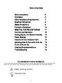
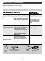
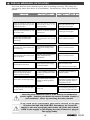
EN
GUIDE TO INSTALLATION AND USE
Cooking Hob
IMPORTANT : Save this manual for the local electrical inspector’s use.
INSTALLER: Please leave this manual with the unit for the owner.
OWNER: Please keep this manual for future reference.
IMPORTANT: Local codes vary. Installation, electrical connections and
grounding must comply with all applicable codes.
IFA-80AL / IFA-80BL
IFA-90AL / IFA-90BL
1
IMPORTANT SAFETY INSTRUCTIONS
1 - Proper Installation - Be sure your appliance is properly grounded and installed
by a qualified technician.
2 - Never Use your Appliance for Warming or Heating the Room.
3 - Do Not Leave Children Alone - Children should not be left alone or unattended
in an area where appliance is in use. They should never be allowed to sit or stand
on any part of the appliance.
4 - Wear Proper Apparel - Loose-fitting or hanging garments should never be worn
while using the appliance.
5 - User Servicing - Do not repair or replace any part of the appliance unless
specifically recommended in the manual. All other servicing should be referred to a
qualified technician.
6 - Storage in or on Appliance - Flammable materials should not be stored near
surface units.
7 - Do Not Use Water on Grease Fires - Smother fire or flame or use dry chemical or
foam-type extinguisher.
8 - Use Only Dry Potholders - Moist or damp potholders on hot surfaces may result
in burns from steam. Do not let potholder touch hot heating elements. Do not use
a towel or other bulky cloth.
9 - Use Proper Pan Size - This appliance is equipped with several, differently sized,
induction elements. Select utensils having flat bottoms, large enough to cover the
surface unit heating element. Proper size pots and pans will also improve efficiency.
10 - DO NOT TOUCH SURFACE UNITS OR AREAS NEAR UNITS - Surface units may
be hot even though they are dark in color. Areas near surface units may become hot
enough to cause burns. During and after use, do not touch, or let clothing or other
flammable materials contact surface units or areas near units until they have had
sufficient time to cool.
11. Do Not Heat Unopened Food Containers - Build-up of pressure may cause
container to burst and result in injury.
12. Never Leave Surface Units Unattended at High Heat Settings - Boil-over causes
smoking and greasy spillovers that may ignite.
13. Do not use aluminum foil, aluminum liners or aluminum containers on the
unit.
2
IMPORTANT SAFETY INSTRUCTIONS
14. Utensil Handles Should Be Turned inward and Not Extend Over Adjacent
Surface Units - To reduce the risk of burns, and spillage due to unintentional
contact with the utensil, the handle of a utensil should be positioned so that it is
turned inward, and does not extend over adjacent surface units.
15. Do not Cook on Broken Cooktop - If cooktop should break, cleaning solutions
and spillovers may penetrate the broken cooktop and create a risk of electric shock.
Contact a qualified technician immediately.
16. Clean Cook-Top With Caution - If a wet sponge or cloth is used to wipe spills on
a hot cooking area, be careful to avoid steam burn. Some cleaners can produce
noxious fumes if applied to a hot surface.
CAUTION
Do not store items of interest to children in cabinets above or around the cooktop children climbing on the cooktop to reach items, could be seriously injured.
3
Table of Contents
Before Installation
Installation
Other Installation Requirements
Electrical Connection
Safety Precautions
Principle of Induction
Glass Top, Coil Size and Controls
Controls and Operation
Heating Zones, Coil Sizes & Utensils
Power Sharing
Utensils for Your Induction Unit
Matching Pots & Pans with Coils etc.
To Do or Not to Do
Cleaning Recommendations
Troubleshooting
5
6
7
8
9
10
11
12
12
12
13
13
14
15
16
Your safety and ease of use are important to us.
In this manual we have provided a number of safety warnings and as well as numerous tips
and hints for using the unit. Warnings and tips are marked with the following symbols:
Safety warning symbol
Tips and hints
4
Before Installation
If you are receiving the unit from a
transportation company, it is customer’s
obligation to inspect thepackage and note
any damage on the delivery receipt. After
delivery, have your induction cooktop
carefully unpacked, and again check forany
visible damage. If you find any damage onthe
unit at this point, immediately inform your
dealer or distributor. Although the
responsibility for shipping lies with the
carrier, your dealer/ distributor will assist you
with your claim.
If the unit is not supposed to be installed for
some time, you should keep it in its original
packaging, stored in a dry and safe place.
Read through the section of this manual
which pertains to installation, and make sure
that all of the requirements can be provided
or are already provided. Ensure that your
electric power supply is correct.
Before you install the unit, you should take a
moment to write down the information from
your nameplate and fill-out the table on page
19, for future after-sale servicing needs. This
information will be required every time you
call for any service on your unit.
5
1 / INSTALLATION
To install the cooktop, cut out a rectangular
opening in the counter as shown on the
drawing and table below. Also, ensure that
you have a minimum of 10 mm (3/8”) of
space in the back of the unit, between the
rim and backsplash on your counter (or wall
if no backsplash) for ventilation.
A self-adhesive gasket is supplied with your
unit. Before setting the cooktop in place
install this gasket by sticking it underneath
the rim.
IApply the gasket only along the front rim
and on both sides. This gasket will prevent
most of the spills from entering the cabinet
below and will keep the unit in place. Once
the gasket is installed, place the cooktop in
the opening, and lay it on the rim. Do this
carefully - do not drop the unit into the cutout. Make sure that the unit is sitting
properly on its rim all around the perimeter.
f your counter is produced from porous materials which tend to swell if in contact
with humidity and water, to better protect the cut-out, use proper sealants on the
edge which would prevent any penetration of humidity and water.
Chamfer all exposed edges of decorative laminates to prevent further chipping.
Radius corners of the cut-out and file them to ensure smooth edges and prevent
corner cracking.
Rough edges and inside corners which are not rounded as well as forced fits can
contribute to cracking of counter top laminate.
Cut-out dimensions
31 1/8 “
36 15/16 “
20 3/8 “
790 mm IF-80
938 mm IF-90
518 mm
72 mm
Name plate and rating
plate located on bottom
of cooktop.
2.7“
19 1/2 “
496 mm
29
1/2
“
m
cmm
104
750 mm
4 1c0 m
m m 900 mm
7/16
35
“
mm
0m
41 c
A
4c
m
10 mm = 3/8”
6
Other Installation Requirements
etc.) which could obstruct the air inlet under
your induction cooktop.
Cabinet Above
Cabinet Above
Although induction-cooktop heat rejection is
minimal and the unit does not create any
fumes in operation, such unit must be
installed underneath a properly sized
ventilation hood for exhausting any smell,
vapor and smoke created by cooking itself.
Cross
Section
750
mm
750
mm30” (30”)
10 [3/8"
[3/8”]]
10
Minimum
Clearance
Requirements
50 mm
Air
Intake
(2”)
Also, a proper downdraft system can be
used for ventilation.
A minimum vertical clearance of 750 mm
[30”] is required between the top of the
cooking surface and the bottom of any
unprotected combustible material, such
as cabinets, wooden trim etc.
Exhaus
Cabinet
below
Cabinet Belo
w
In the back, leave a minimum of 10 mm
[3/8”] between the cooktop edge and
adjacent vertical surfaces (backsplash,
wall, high cabinets etc.). This space is
needed for the unit to breath properly.
During cooking, built-in fan inside the
cooktop will operate constantly to keep the
internal components cool. The air intake is
on the bottom of the cooktop box, and the
warm air exhaust is located on the front of
the rim, as shown on the schematic. If the air
intake or the exhaust is obstructed, the
cooktop safeties will either diminish the
power output or shut down the unit.
If a downdraft ventilation system is used,
a minimum of 6 mm (1/4”) of clearance
is required between the rear edge of the
cooktop and the downdraft snorkel.
Leave a minimum of 50 mm [2”]
underneath the unit for the air intake.
We suggest that you should periodically
check that there are no objects (dust, paper,
Your cook-top must always breath adequately. Make sure that the air inlet and its
exhaust are not obstructed.
The unit must not be installed above a washing machine, a refrigerator or a deepfreezer box
To eliminate the risk of burns or fire by reaching over heated surface units, cabinet
storage space located above the surface units should be avoided.
The unit must be installed such that it can be pulled without difficulty out of the cut-out
for servicing or cleaning.
Never glue, silicone or wedge the unit inside its cut-out.
7
Electrical Connection
cooktop electrical characteristics are:
Operating voltage................................................... 240 V~ 60 Hz
Maximum power output .............................................. 7200 W 30A
Connect to .............. 240 V, 60 Hz, 2 Pole+G, 40 A minimum supply,
(3 conductors #10 AWG)
Electrical wiring information
•240 V
An adequate electrical supply must be provided for this unit. All wire connections and
grounding must be done in accordance with
local electrical codes, or if these codes are
not established, then with the National Electrical Code, ANSI/NFPA No. 70 in the US , or
with the Canadian Electrical Code, CAN/CSA
C22.1, in Canada.
Connect the 3 wires as per the following
colour code
Green
Red
This unit comes equipped with three connection wires in a flexible conduit. The conduit
must be routed and properly connected to an
approved, owner-supplied, electrical, wall
junction-box. An approved connector must be
used for connecting the conduit to the junction box. A three wire, 2 poles, 240 V, 60 Hz
service with minimum 40 A circuit protector
must be provided. The red and the black wire
from the unit are to be connected to the service (”hot”) wires, and the green wire is to be
connected to the ground conductor.
Phase 1
L
L
Earth
Phase 2
Black
responsible for any unit malfunction due to an
inadequate electrical supply (inadequate cable size, low voltage, power surge etc). Furthermore, if your residence has only a 208 V
supply system, and if the voltage frequently
fluctuates, your cooktop may not function properly
The circuit protector for the unit should be
properly marked inside electric panel and anybody using the unit, or technician servicing
the unit, should be advised of circuit protector’s location, so that the power to the unit can
be disconnected when necessary.
It is recommended that the connection to
electrical supply is done by a qualified electrician.
Once the unit is properly fitted and connected
to the electrical power supply, turn the unit on
to ensure that all elements and controls are
operating well.
If there is any visible physical damage on the
conduit and the wires, the unit must not be
connected to the mains. A qualified electrician
or approved service agent should be called in
to replace the wires and the conduit.
Note that your unit is designed for a stabile
and steady 240 V supply and the manufacturer, its distributors and dealers cannot be held
8
Safety Precautions - Read before operating your cooktop
Your induction-cooking unit has been
designed for residential use and food
preparation, and all of the safety parameters
have been rectified accordingly.
will disable the heating section of the unit.
This occurrence is called ‘long press’ and
when it happens “-” signs will appear on
power displays. The unit will act the same if
there is an accumulation of some liquid on
the keypad area, or if a damp cloth is left
sitting on the keypad. The section will
become operational again once the spill or
the object/hand is removed, and the
element turned back on.
The unit incorporates numerous safety
devices and controls, and a few devices will
be mentioned here.
- A number of sensors monitor temperature
of internal components. If any of these
sensors senses that the component
temperature is above the limit, the power
output of the unit will automatically be
reduced, allowing the component to cool
down. Once this is achieved, the unit will
continue to operate normally at the output
level set initially by the operator.
In an effort of constantly improving our
products, we reserve the right to make any
changes to internal components, as well as,
to make any(cosmetic) modifications on the
outside frame.
This unit does not contain any asbestos or
asbestos based components.
- Each induction coil is equipped with a
sensor which is continuously monitoring the
temperature of the bottom of the pan to
prevent the pan from overheating.
This unit has been tested and certified under
FCC part 15 and CFR Title 47, Part 18, for
electromagnetic interference.
- Each induction coil is equipped with a pan
sensing device. This device will not allow the
heating element to turn on unless it senses
a cooking utensil on the coil covering
enough surface area. The indication that the
coil is not running is the flashing of the
digital display. Once the pan is put properly
on the coil, the digital display will become
steady. Note that a small object such as a
fork, a spoon, a piece of jewelry, etc. will not
be mistaken for a cooking utensil, and it will
not trigger this sensor. Moreover, this device
will distinguish between cooking utensils
which are and are not suitable for induction
cooking. If a cooking utensil which is not
suitable for induction cooking is placed on a
coil there will be no power output on the
coil.
The users with heart pacemakers must
consult with the pacemaker manufacturer
prior to using this cooktop which
incorporates induction heating source.
- If an operator leans on the keypad by
chance for more then ten seconds, controls
If a crack appears in the glass surface, disconnect the unit immediately to avoid any risk
of electric shock. If the unit is connected directly to supply inside a junction box, then
disconnect its breaker, or remove fuses manually.
Do not re-use your cooktop until the glass top is changed.
When cooking never use aluminum foil and never place products wrapped in aluminum foil, nor
products deep-frozen in aluminum packs on the hob. Aluminum foil could melt and damage
vitroceramic glass surface beyond repair.
9
The principle of induction
When an induction element - also called: ‘a
heating zone’, or simply: ‘a coil’ - is switched
on, the appropriate utensil is used, and a desired level of heating power selected, the electronic circuit unit (‘induction generator’ or ‘inverter’) powers up the induction coil which
creates a magnetic field. This magnetic field
continuously changes in terms of frequency
and intensity, and this creates induced currents in the bottom of the utensil and ultimately results in heat. The heat is transferred directly to the food being cooked.
C
B
A
+
-
A Induction coil
B Inverter
Induced currents
C
Thus, induction heat makes the utensil a direct source of heat, featuring high level of efficiency with extremely low energy loss and unparalleled heating level control.
- if the utensil is fully removed from the coil,
the power output will be instantaneously reduced to ‘0’, and, eventually, the controls will
turn the element off after a minute, unless the
utensil is returned back onto the coil.
With induction cooking there is very little ‘heating inertia’. Induction cooking elements do
not incorporate a heat generating element unlike convectional electric rings, halogen or
radiant elements etc. - therefore, heat levels
can be changed very quickly.
When compared to the other methods of cooking, induction cooking has a very low level
of ambient heat, thus makes cooking more
pleasurable, with a reduced need for ventilation.
Energy efficiency for induction is within range
of 90-95%, compared with 55-65% for conventional and radiant element, or 45% - 55% for
gas fueled burners. The energy efficiency
contributes to substantial energy savings,
both beneficial to the owner as well as the environment.
Finally, the vitroceramic glass as a cooking
surface barely becomes hot and this makes
cleaning much easier.
Induction cooking elements are sensitive to
the utensil type being used :
- if there is no utensil placed on the coil, or if
the utensil is not of induction grade, there will
be no power emitted by the coil;
- if the utensil is placed partially on the coil, or
if it is smaller than the coil, the internal sensors will reduce power to the coil; The Principle of Induction
For a proper choice of utensils, please refer to “Utensils for Your Induction”
When using induction elements, some utensils may produce
faint humming sound. This is a normal occurrence - the noise
is a result of vibrations caused by induced currents.
10
Glass Top, Coil Size and Controls
18 cm (8”)
IF-80
50 W à 2800 W
22 cm (9”)
22 cm (9”)
50 W à 2800 W
50 W à 2800 W
Cooking zone
16 cm (6” 1/2)
Control zone
8 5 5 7
50 W à 2200 W
IF-90
9 9 3 2
16 cm(6” 1/2)
22 cm (9”)
50 W à 2200 W
50 W à 2800 W
Cooking zone
28 cm
50 W à 3600 W
22 cm (9”)
16 cm (6” 1/2)
50 W à 2800 W
Control zone
50 W à 2200 W
• DESCRIPTION OF THE CONTROL PANEL
• ADJUSTING THE POWER
Press the + or - power touch controls.
or on pre-select touch controls.
Touch Display
A
B
D
A Start/stop touch control.
B Power - + touch controls.
Use
6
medium low heat
10
high
12
D Power pre-select touch controls.
Setting
moderate heat
Maximum maximum
Tip
• POWERING ON
For simultaneous use, favour the use
of cooking zones located on opposite sides
of the hob.
On the same side, the use of a cooking
zone at maximum power results in an
automatic limitation of the other cooking
zone on that side, which is indicated in the
power level display.
Press the start/stop touch control for the
zone you want to use. A flashing "0" indicates
that the zone is on. You can then choose the
desired power level.
If you do not select a power level, the cooking
zone will automatically shut off.
11
• WHICH COOKING ZONE
SHOULD YOU USE BASED ON
YOUR COOKWARE?
• POWER SHARING
Under the pretense that only one zone is
used with an adequate utensil covering the
whole surface of the coil, and that power on
the zone is adjusted to the maximum (‘12’):
- the maximum power output of 22 cm (9”)
heating zone is 2.8 kW;
- the maximum power output of 16 cm (6
1/2”) heating zone is 2.0 kW.
If only one coil is employed, it can be
utilized at its maximum power, but as soon
as the other coil is turned on, the controls
adjust the power on both coils
automatically for ‘power sharing’. This
power sharing is administered by unit’s
microprocessors, which will alternate
power between the two elements. There are
two factors affecting improved power
sharing on your cooktops.
A
Cooking
zone
Diameter A
16 cm (6 1/2”)
10 ..... 18 cm (4..7”)
18 cm (7)
12 ..... 22 cm (43/4”..81/2”)
22 cm (9 ”)
18 ..... 24 cm (7..9 ”)
The first is the application of an improved
technology for power sharing - not using
common relays, but rather semiconductors
which makes power sharing quicker, thus
more efficient. The second factor is that,
when in a power-sharing mode, two zones
can share full, 3.6 kW, power output of the
inverter.
1/2
Tip
To check the suitability of your
cookware:
Place the vessel on a cooking zone at
power level 4.
If the display remains on, your cookware is
compatible.
If the display flashes, your cookware cannot
be used with induction cooking.
You can also use a magnet to test the
cookware.
If a magnet "sticks" to the bottom of the
cookware, it is compatible with induction.
Note that the controls will not allow both
zones to operate at full power, and the
power will be adjusted automatically - e.g. if
the power on one zone is adjusted to a
maximum, and the other zone is turned on
and power level also adjusted to its
maximum, the power level on the first zone
will automatically become lower. This
change will be visible on digital displays.
The controls are set in such a manner that
the last instruction (command) given to an
element is always a priority.
12
Utensils for Your Induction
Induced current can be created only in
materials which have magnetic properties.
Thus, utensils for use with an induction unit
must be made from a ferromagnetic material
or have inserts with magnetic properties.
Your household may already have cookware
suitable for induction cooking, and you may
test any utensil with an induction element.
Incorporated controls are able to recognize
a suitable utensil. To perform a utensil test:
induction cooking, but most manufacturers
make such utensils in layers for better heat
distribution, and a good number of such
pots and pans can be used with induction.
To make sure if a stainless steel utensil can
be used perform the utensil test.
- Turn an element on and adjust power to any
level - you will notice that the digital power
display is flashing.
- Place your utensil on the coil. If the piece
being tested is suitable for induction
cooking, the display will become steady.
However, if it keeps flashing, the utensil
cannot be used on your induction unit.
- If the utensil is empty, remove it from the
coil immediately after you have done test and
turn the element OFF.
Pots and pans which do not have a flat
bottom still may be used, however they
should not be overly deformed.
Use of utensils with enameled coated base
will prevent the glass top of your unit from
getting scratched.
Cookware made from glass, ceramic,
earthenware, aluminum and copper pots and
pans and non-magnetic stainless steel
cookware are not suitable for induction
cooking.
Matching Pots & Pans with Coils, etc.
Small elements,16 cm (6 1/2”), are best
utilized:
- With small utensils - but normally not
smaller then 10 cm (4”);
- For slow cooking and simmering (sauces,
creams, etc.);
- For cooking small quantities of food.
Large elements, 22 cm (9”), are primarily
designed for day-to-day cooking needs and
most commonly used pans - 18 to 25 cm (7
to 9 1/2”) in diameter.
Another simple test to determine if a piece of
cookware can be used on an induction
cooktop is the ‘magnet test’. Use a magnet
and place it on the utensil. If the magnet
sticks to it, the piece will work with
induction.
Utensils compatible with induction are:
• Cookware made of enamel coated steel
with or without a non-stick coating.
• Cast iron cookware with or without enamel
coated base.
• Stainless steel pots and pans designed for
induction cookware.
When cooking large quantities of food, it is
always better to use a large diameter pan
and a larger coil, thus better and more
efficient heat distribution will be achieved
and food cooked evenly.
Note:
Stainless steel used for utensils is nonmagnetic, in most cases, and unsuitable for
Utensils with thick flat bases should be chosen for the benefit of uniform heat
distribution.
Never leave an empty piece of cookware on an induction heating element for more then a few
seconds. If a utensil is left on an element at full power, temperature of the dish may
increase rapidly, the safeties would not engage, and this may damage your utensil,
the cooktop, and could result in an injury or a damage to your property.
13
To Do or Not To Do
You must:
- Avoid storing flammable products in the
cabinets under your cooktop.
- Always place your utensil such that its
center is aligned with the centre of the coil.
- Never leave an empty utensil on an
induction heating element, even when the
element is turned OFF.
- Avoid hitting the vitroceramic glass with
utensils or any hard objects - the glass
surface is highly resistant but not
unbreakable.
- Only use maximum power for boiling and
frying.
- Pick-up your utensils when moving them
around. Do not slide them and avoid
excessive rubbing of the top, as this leaves
scratches and erases the markings .
- Never try heating up a closed can.
- Avoid using utensils with rough or
deformed bottoms.
- Avoid storing solid and heavy items in the
cabinets above your cooktop. They may
unintentionally drop and damage the glass.
To Do or Not To Do
- Avoid pre-heating your non-stick pans (e.g.
with teflon coating) at maximum heat.
- Avoid leaving any metal cooking
accessories, knives and forks, or metal
objects on the hob. They may get hot if left
close to any heating element in use.
Do not connect any appliances to the plugs above or near to the induction cooktop;
connection cable insulation can melt if in contact with heat, and this may result in an
injury and a property damage.
Your cooktop must never be used as a storage space or surface for piling up of any
material.
14
3 / DAILY CARE OF YOUR APPLIANCE
• MAINTAINING YOUR APPLIANCE
Cleaning of an induction cooktop is easy. Read and follow these
recommendations:
TYPE OF STAINS/SPOTS
WHAT TO DO
ACCESSORIES or
AGENTS EMPLOYED
Minor
Soak the area to be cleaned with
soapy water, then wipe it.
Cleaning sponges & mild
detergents
Soak the area to be cleaned with
warm soapy water. Use a special
scraper for vitroceramic glass to
remove grease and food particles.
Finish off with a cleaning sponge,
then wipe it clean.
Cleaning sponges, mild
detergents and cleaning
agents for vitroceramic
glass
Accumulated burn-on
stains.
Rings and traces of lime
scale.
Burn-on stains following
sugar spillage, melted
aluminium or plastic.
Nonabrasive
Paste
Apply warm white vinegar on the
stain. Leave to act then wipe off
with a soft cloth. OR Use a
commercial cleaner on affected
area. Note that such cleaner may
leave stains on stainless steel
frame, thus protect exposed
stainless steel.
Cleaning cloth,white
vinegar, or diluted
de-liming agent.
Apply special vitroceramic
glass cleaner on the surface,
preferably one which contains
silicone (protective action).
Leave to act, then finish off with
a cleaning sponge, then wipe it
clean.
Vitroceramic cleaning
agents and sponge.
Ordinary Sponge or Special
Sponge for Delicate Items
Powder
15
Abrasive-backed
sponge
4 / SPECIAL MESSAGES, DIFFICULTIES
You have doubts about whether your hob is working correctly. This does not
necessarily mean that there is a breakdown. Nevertheless, check the following
points.
PROBLEM
POSSIBLE CAUSES
WHAT SHOULD YOU DO?
When you switch the unit on, the
supply-line breaker trips off or the
supply-line fuse burn.
Your unit may be connected
incorrectly,or there is an
internal problem.
Have the connection checked
first. If the connection is OK,
contact your service agent.
When you switch elements on, only
one element works.
There is an internal problem
with the unit.
Contact your service agent.
The fans keep running for a few
minutes after the unit has been
switched off,
The electronics are cooling
down
This is a normal occurrence.
The top of the unit is always
lukewarm (even when elements are
not switched on).
The electronic components are
under power and they create
heat.
This is a normal occurrence.
Your hob makes faint clicking noise
when in operation.
This noise occurs when the power is
being shared between two
induction coils.
This is a normal occurrence.
The unit doesn't work at all.
There may be a power supply
or internal problem.
Check your beakers (fuses)
and/or connection cable.
If OK, contact your service agent.
After turning an element ON and
having utensil placed on the coil,
there is no heat and the digital
indicator continues flashing..
The utensil you are trying to use
is not compatible with induction
cooking or its diameter is under
10 cm. (4”).
Use another utensil suitable for
induction cooking.
Utensil makes noise during cooking.
Your utensil creates noise from
vibrations caused by induced
current .
Under high power this
phenomenon is normal with some
types of pots and pans. There is
no danger for the hob.
The hob gives off a smell when first
used for cooking.
A new unit
Use each heating element for an
hour with a pan filled with water.
Servicing of an induction unit is to be done by an authorized
service agent. Contact your dealer for service location closest to
your residence. Never try servicing the unit yourself.
If any crack on the vitroceramic glass can be noticed, or the glass
is broken DO NOT USE THE UNIT. Disconnect the electrical
supply to the unit by tripping the breaker off (if the unit is hardwired to the supply) or just unplug the unit (if there is a plug on
the supply cable).
16
99645821 02/08
FAGOR AMERICA, INC.
PO BOX 94
LYNDHURST, NJ 07071
Toll Free: 1.800.207.0806
Email: [email protected]
www.fagoramerica.com
The manufacturer reserves the right to modify the items described in this manual.
Le producteur se réserve le droit de modifier les articles décrits dans cette guide.
El fabricante se reserva el derecho de modificar los productos descritos en este manual.