1
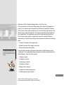
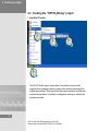
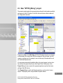
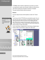
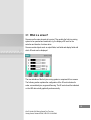
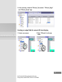
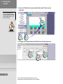
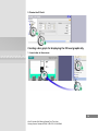
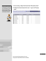
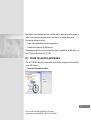
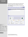
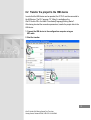
SIMATIC HMI
WinCC flexible 2005
Getting Started First Time User
Order number 6ZB5370-1CL02-0BA0
Release 05/2005
A5E00279548
Safety Guidelines
This manual contains notices which you should observe to ensure your own personal safety as well as to avoid
property damage. The notices referring to your personal safety are highlighted in the manual by a safety alert
symbol, notices referring to property damage only have no safety alert symbol.
Danger
indicates an imminently hazardous situation which, if not avoided, will result in death or serious injury.
Warning
indicates a potentially hazardous situation which, if not avoided, could result in death or serious injury.
Caution
used with the safety alert symbol indicates a potentially hazardous situation which, if not avoided, may
result in minor or moderate injury.
Caution
used without safety alert symbol indicates a potentially hazardous situation which, if not avoided, may
result in property damage.
Notice
used without the safety alert symbol indicates a potential situation which, if not avoided, may result in
an undesirable result or state.
Wehn several danger levels apply, the notices of the highest level (lower number) are always displayed. If a
notice refers to personal damages with the safety alert symbol, then another notice may be added warning of
property damage.
Qualified Personnel
The device/system may only be set up and operated in conjunction with this documentation. Only qualified
personnel should be allowed to install and work on the equipment. Qualified persons are defined as persons
who are authorized to commission, to earth, and to tag circuits, equipment and systems in accordance with
established safety practices and standards.
Intended Use
Please note the following:
Warning
This device and its components may only be used for the applications described in the catalog or
technical description, and only in connection with devices or components from other manufacturers
approved or recommended by Siemens.
This product can only function correctly and safely if it is transported, stored, set up and installed
correctly, and operated and maintained as recommended.
Trademarks
All designations marked with ® are registered trademarks of Siemens AG. Other designations in this
documentation might be trademarks which, if used by third parties for their purposes, might infringe upon the
rights of the proprietors.
Copyright Siemens AG, 2005. All rights reserved
Reproduction, transmission or use of this document or its contents is not permitted without
express written authority. Offenders will be liable for damages. All rights, including rights
created by patent grant or registration of a utility model or design, are reserved.
Siemens AG
Bereich Automatisierungs- und Antriebstechnik
Geschaeftsgebiet Industrie-Automatisierung
Postfach 4848, D-90327 Nürnberg
Siemens Aktiengesellschaft
Disclaimer of Liability
We have checked the contents of this manual for agreement with the hardware and
software described. Since deviations cannot be precluded entirely, we cannot guarantee
full agreement. However, the data in the manual are reviewed regularly, and any
necessary corrections will be included in subsequent editions. Suggestions for
improvement are welcomed.
Siemens AG 2005
Technical data subject to change
Contents
1
Welcome . . . . . . . . . . . . . . . . . . . . . . . . . . . . . . . . . . . . . . . . . . . . . . . . . . . . . . . . 2
2
2.1
2.2
2.3
Creating a project . . . . . . . . . . . . . . . . . . . . . . . . . . . . . . . . . . . . . . . . . . . . . . . . 6
What is a project? . . . . . . . . . . . . . . . . . . . . . . . . . . . . . . . . . . . . . . . . . . . . . . . . . 7
Creating the “OP77B_Mixing” project . . . . . . . . . . . . . . . . . . . . . . . . . . . . . . . . . . 8
New “OP77B_Mixing” project . . . . . . . . . . . . . . . . . . . . . . . . . . . . . . . . . . . . . . . 13
3
Creating the screens . . . . . . . . . . . . . . . . . . . . . . . . . . . . . . . . . . . . . . . . . . . . . 24
3.1 What is a screen? . . . . . . . . . . . . . . . . . . . . . . . . . . . . . . . . . . . . . . . . . . . . . . . . 25
3.2 Configuring fill level displays . . . . . . . . . . . . . . . . . . . . . . . . . . . . . . . . . . . . . . . . 26
4
4.1
4.2
4.3
4.4
Configuring the alarms . . . . . . . . . . . . . . . . . . . . . . . . . . . . . . . . . . . . . . . . . . .
What is an alarm? . . . . . . . . . . . . . . . . . . . . . . . . . . . . . . . . . . . . . . . . . . . . . . . .
Configuring discrete alarms . . . . . . . . . . . . . . . . . . . . . . . . . . . . . . . . . . . . . . . . .
Configuring analog alarms. . . . . . . . . . . . . . . . . . . . . . . . . . . . . . . . . . . . . . . . . .
Configuring an alarm view . . . . . . . . . . . . . . . . . . . . . . . . . . . . . . . . . . . . . . . . . .
34
35
35
40
43
5
5.1
5.2
5.3
Creating the recipes . . . . . . . . . . . . . . . . . . . . . . . . . . . . . . . . . . . . . . . . . . . . .
What is a recipe? . . . . . . . . . . . . . . . . . . . . . . . . . . . . . . . . . . . . . . . . . . . . . . . . .
Creating a new recipe . . . . . . . . . . . . . . . . . . . . . . . . . . . . . . . . . . . . . . . . . . . . .
Configuring a Recipe view . . . . . . . . . . . . . . . . . . . . . . . . . . . . . . . . . . . . . . . . . .
46
47
48
53
6
Adding screen changes . . . . . . . . . . . . . . . . . . . . . . . . . . . . . . . . . . . . . . . . . . 56
6.1 What are screen changes? . . . . . . . . . . . . . . . . . . . . . . . . . . . . . . . . . . . . . . . . . 57
6.2 Adding screen changes . . . . . . . . . . . . . . . . . . . . . . . . . . . . . . . . . . . . . . . . . . . . 58
7
Testing and simulating the project. . . . . . . . . . . . . . . . . . . . . . . . . . . . . . . . . . 62
7.1 Procedure . . . . . . . . . . . . . . . . . . . . . . . . . . . . . . . . . . . . . . . . . . . . . . . . . . . . . . 63
7.2 Simulating the project . . . . . . . . . . . . . . . . . . . . . . . . . . . . . . . . . . . . . . . . . . . . . 64
8
Transferring the project (option) . . . . . . . . . . . . . . . . . . . . . . . . . . . . . . . . . . . 70
8.1 Check connection parameters . . . . . . . . . . . . . . . . . . . . . . . . . . . . . . . . . . . . . . . 71
8.2 Transfer the project to the HMI device. . . . . . . . . . . . . . . . . . . . . . . . . . . . . . . . . 73
1
WinCC flexible 2005 Getting Started First Time User
Getting Started, Release 05/2005, 6ZB 5370-1CL02-0BA0
1 Welcome
2
Welcome to WinCC flexible Getting Started - First Time User.
Using an example of a fruit juice filling system, this manual will illustrate how
easy it is to create the user interface for an HMI device using WinCC flexible.
The fruit juice mixing system produces juice, nectar and beverage drinks in the
flavors orange, apple and tropical. The necessary ingredients are available in
four supply tanks. The ingredients are mixed in mixing tanks and then filled.
The fruit juice mixing system is operated by means of a small HMI device
connected to it. The fruit juice mixing system operator can perform the following
tasks:
• Control the fill level in the supply tanks
• Monitor the status of the supply line valves
• Enter and transfer mixture ratios
“Configuring” relates to the
creation and configuration of
the user interface for an HMI
device.
In order that the operator can perform these tasks, the HMI device must be
“configured”. The configuration steps necessary to do this are explained in the
Getting Started - First Time User manual:
• Creating a project
• Creating the screens
• Configuring the alarms
• Creating the recipes
• Adding screen changes
• Testing and simulating the project
• Transferring the project (option)
3
WinCC flexible 2005 Getting Started First Time User
Getting Started, Release 05/2005, 6ZB 5370-1CL02-0BA0
1 Welcome
The WinCC flexible CD-ROM enclosed contains programs with which you can
complete these configuration steps. In addition, install the WinCC flexible edition
“Compact”, “Standard” or “Advanced” on your configuration computer.
The following components are used for the example in this Getting Started - First
Time User manual:
Only the configuration computer is required for the configuration steps
mentioned. If the project is to be transferred to an HMI device, the OP 77B HMI
device or another HMI device from the 170 series is required.
If an HMI device with different functionality is used, the configuration steps
necessary may deviate from the steps explained.
4
WinCC flexible 2005 Getting Started First Time User
Getting Started, Release 05/2005, 6ZB 5370-1CL02-0BA0
5
WinCC flexible 2005 Getting Started First Time User
Getting Started, Release 05/2005, 6ZB 5370-1CL02-0BA0
2 Creating a project
6
2.1 What is a project?
The basis for configuring the user interface is the project.
Create and configure all the objects in the project which are necessary to
operate and monitor the fruit juice mixing system, e.g.
• Screens, to depict and operate the fruit juice mixing system.
• Tags, to transfer data between the HMI device and fruit juice mixing system.
• Alarms, to indicate the operating status of the fruit juice mixing system on the
HMI device
7
WinCC flexible 2005 Getting Started First Time User
Getting Started, Release 05/2005, 6ZB 5370-1CL02-0BA0
2 Creating a project
2.2 Creating the “OP77B_Mixing” project
1. Start WinCC flexible:
The WinCC flexible project wizard opens. The project wizard provides
supports when creating a project by guiding users step-by-step through the
configuration settings. The project wizard has various scenarios for frequently
required configurations. Complete the configuration settings by selecting the
scenarios provided.
8
WinCC flexible 2005 Getting Started First Time User
Getting Started, Release 05/2005, 6ZB 5370-1CL02-0BA0
2. Create a new project:
9
WinCC flexible 2005 Getting Started First Time User
Getting Started, Release 05/2005, 6ZB 5370-1CL02-0BA0
2 Creating a project
3. To operate the fruit juice mixing system, only one HMI device and one
control unit are needed. Therefore, select “Small Machine”:
10
WinCC flexible 2005 Getting Started First Time User
Getting Started, Release 05/2005, 6ZB 5370-1CL02-0BA0
4. Select the “OP 77B” HMI device. Use the predefined
“SIMATIC S7 300/400” as controller:
5. Click on “Next” to apply the standard settings provided on the pages
“Screen Templates”.
6. Click on “Next” to apply the standard settings provided on the
“Libraries” pages.
11
WinCC flexible 2005 Getting Started First Time User
Getting Started, Release 05/2005, 6ZB 5370-1CL02-0BA0
2 Creating a project
7. Then enter information on the project:
12
WinCC flexible 2005 Getting Started First Time User
Getting Started, Release 05/2005, 6ZB 5370-1CL02-0BA0
2.3 New “OP77B_Mixing” project
The project wizard creates the new project according to the information specified
and opens it in WinCC flexible. To the left is the tree structure that contains all
the configurable elements:
Projects are edited in the Work Area. All WinCC flexible elements are arranged
on the borders of the work area. With the exception of the work area, you can
organize, configure and, for example, move or hide any of the elements to suit
your individual requirements.
All component parts and all available editors of a project appear in a tree structure and can be opened from there in the Project View. Furthermore, in the
Project View you have access to the project properties as well as the device
settings of the HMI device.
The Property View is used to edit object properties, e.g. the color of screen
objects. The property view is only available in specific editors.
13
WinCC flexible 2005 Getting Started First Time User
Getting Started, Release 05/2005, 6ZB 5370-1CL02-0BA0
2 Creating a project
The Toolbox contains a selection of objects that you can add to your screens,
e.g. image objects or operator control elements. In addition, the toolbox also provides libraries containing object templates and collections of faceplates.
The project wizard has already created some elements:
Screens
Some pre-configured screens and the templates are stored in the “Screens”
area.
The Error Alarm Window displays messages which have
just arrived.
The System Event Window
displays HMI device messages.
The start screen for the OP 77B HMI device is automatically opened in the workbench area to the right of the root structure. The Start screen contains two alarm
windows positioned one above the other (Error Alarm Window and System
Alarm Window) which are required for later operation of the HMI device for the
fruit juice mixing machine. The gray shading of the Alarm Window indicates that
this alarm window is inserted in the template.
You do not need the pre-configured screens for the following configuration steps.
Therefore, delete all screens with the exception of the “Start screen”:
14
WinCC flexible 2005 Getting Started First Time User
Getting Started, Release 05/2005, 6ZB 5370-1CL02-0BA0
Connections
In addition, the connection settings between the HMI device and controller have
already been defined.
15
WinCC flexible 2005 Getting Started First Time User
Getting Started, Release 05/2005, 6ZB 5370-1CL02-0BA0
2 Creating a project
Customizing the template
Objects inserted in the template are those which should appear in every screen,
e.g. the previously mentioned alarm windows.
Since the alarm windows only appear when a message occurs while the fruit
juice mixing machine is in operation, the display of the alarm windows can be
suppressed during configuration. To do this, deactivate the level in which the
alarm windows are inserted.
1. Open the template:
16
WinCC flexible 2005 Getting Started First Time User
Getting Started, Release 05/2005, 6ZB 5370-1CL02-0BA0
2. Set the active layer to “0” (2), deactivate the layer with the three alarm
windows (3) and close the template (4):
17
WinCC flexible 2005 Getting Started First Time User
Getting Started, Release 05/2005, 6ZB 5370-1CL02-0BA0
2 Creating a project
Setting up the workbench area
The WinCC flexible Workbench consists of individual windows which can be
arranged as required around the work area. The following section describes how
to “dock” the Object view in the Project view.
“Docking” refers to the integration of a window into the
WinCC flexible workbench.
You can automatically hide
docked frames in order to
increase your workspace.
1. Unhide the Object view (1) and configure the view so that it is not
automatically hidden (2):
18
WinCC flexible 2005 Getting Started First Time User
Getting Started, Release 05/2005, 6ZB 5370-1CL02-0BA0
2. Docking the Object view in the Project view:
19
WinCC flexible 2005 Getting Started First Time User
Getting Started, Release 05/2005, 6ZB 5370-1CL02-0BA0
2 Creating a project
The Object view contains the contents of the area selected in the Project view,
e.g. Screens:
20
WinCC flexible 2005 Getting Started First Time User
Getting Started, Release 05/2005, 6ZB 5370-1CL02-0BA0
Resetting window arrangement
The docking of windows at the correct position requires a little practice. For this
reason, the arrangement of the windows can be reset to their original setting at
any time:
21
WinCC flexible 2005 Getting Started First Time User
Getting Started, Release 05/2005, 6ZB 5370-1CL02-0BA0
2 Creating a project
Interrupting configuration
In order to interrupt work on the configuration, e.g. to continue it on the next day,
save the project. When saved for the first time, the user is prompted to enter a
name for the project:
22
WinCC flexible 2005 Getting Started First Time User
Getting Started, Release 05/2005, 6ZB 5370-1CL02-0BA0
The next time WinCC is started, the project is displayed in the project wizard:
23
WinCC flexible 2005 Getting Started First Time User
Getting Started, Release 05/2005, 6ZB 5370-1CL02-0BA0
3 Creating the screens
24
3.1 What is a screen?
Screens are the main elements of a project. They enable the fruit juice mixing
system to be operated and monitored, e.g. the display of fill levels or the
selection and transfer of mixture ratios.
Screens contain objects such as output fields, text fields and display fields with
which fill levels can be displayed.
The user interface of the fruit juice mixing system is comprised of four screens.
The following section explains the configuration of the fill level indicators for
water, concentrated juice, sugar and flavoring. The fill levels should be indicated
on the HMI device both graphically and numerically.
25
WinCC flexible 2005 Getting Started First Time User
Getting Started, Release 05/2005, 6ZB 5370-1CL02-0BA0
3 Creating the
screens
3.2 Configuring fill level displays
The following objects are required to configure the fill level displays:
• Tags to store the fill levels
• Output fields for displaying fill levels in numeric form
• Bar graphs for displaying fill levels graphically
• Text fields for labeling
Creating fill level tags:
The tags store the tank fill
levels which are determined
by measuring transmitters.
The data is transferred
between the controller and
HMI device via the
communication connection.
1. Create a tag which stores the fill level of the water:
2. Configuring the tag:
26
WinCC flexible 2005 Getting Started First Time User
Getting Started, Release 05/2005, 6ZB 5370-1CL02-0BA0
3. In the same way, create the “FillLevel_Concentrate”, “FillLevel_Sugar”
and “FillLevel_Aroma” tags.
Creating an output field for numeric fill level display
1. Create a new screen:
2. Enter “FillLevels” as the new
name:
27
WinCC flexible 2005 Getting Started First Time User
Getting Started, Release 05/2005, 6ZB 5370-1CL02-0BA0
3 Creating the
screens
3. Insert an IO field in the screen in which the water fill level can be
displayed:
If you drag a tag onto the
screen using drag-and-drop,
an input/output field (IO field)
will be created which is connected to the tag.
4. Configure the output format of the IO field in the Properties view:
28
WinCC flexible 2005 Getting Started First Time User
Getting Started, Release 05/2005, 6ZB 5370-1CL02-0BA0
5. Resize the IO field:
Creating a bar graph for displaying the fill level graphically
1. Insert a bar in the screen:
29
WinCC flexible 2005 Getting Started First Time User
Getting Started, Release 05/2005, 6ZB 5370-1CL02-0BA0
3 Creating the
screens
2. Configure the bar graph in the Properties view:
• Enter the volume of the tank (1) and select the “FillLevel_Water” tag (2, 3):
• Adapt the size (1) and align the bar to the right (2, 3):
• Deactivate the scale indicator:
30
WinCC flexible 2005 Getting Started First Time User
Getting Started, Release 05/2005, 6ZB 5370-1CL02-0BA0
Creating a text field to label the fill level display
1. Insert a text field in the screen:
2. Enter a “W” for water in the Properties view:
3. In the same way, create another text field labeled “l” for liters.
31
WinCC flexible 2005 Getting Started First Time User
Getting Started, Release 05/2005, 6ZB 5370-1CL02-0BA0
3 Creating the
screens
Arranging the text fields, bar graphs and output field.
1. Using the cursor keys, position the two text fields, bar graphs and
output field in the display:
Add the fill level displays for juice, sugar and flavoring
Copy&Paste saves time
when creating objects.
Make sure the correct tags
are interconnected.
1. In the same way, create the fill level displays for juice, sugar and
flavoring:
The fill level display is configured. When the system is running, the operator can
read the current fill levels of the tanks on the HMI device.
32
WinCC flexible 2005 Getting Started First Time User
Getting Started, Release 05/2005, 6ZB 5370-1CL02-0BA0
33
WinCC flexible 2005 Getting Started First Time User
Getting Started, Release 05/2005, 6ZB 5370-1CL02-0BA0
4 Configuring the alarms
34
4.1 What is an alarm?
Alarms indicate events or operating states which occur or prevail in the fruit juice
mixing system. Alarms can be used, for example, for diagnostics purposes when
clearing faults.
Alarms are differentiated as follows:
• Discrete alarms indicate changes of status in the fruit juice mixing system
and are triggered by the controller. They indicate, for example, whether a
valve is open or closed.
• Analog alarms indicate a value has moved outside the limits of the permitted
range.
An analog alarm is triggered, for example, when the speed of a motor drops
below a specific value.
4.2 Configuring discrete alarms
Each tank in the fruit juice mixing system is equipped with an inlet valve.
The following section explains how to configure an alarm view in which the
states (open or closed) of the inlet valves for water, juice, sugar and flavoring are
displayed.
When a valve opens or closes during operation, the corresponding discrete
alarm is triggered.
35
WinCC flexible 2005 Getting Started First Time User
Getting Started, Release 05/2005, 6ZB 5370-1CL02-0BA0
4 Configuring the
alarms
Creating tags to store the states
The states of the valves are stored in the “Valve_Status” tags.
Each status is assigned a bit in the tag.
• Water valve: Bit 0 and Bit 1
• Juice valve: Bit 2 and Bit 3
• Sugar valve: Bit 4 and Bit 5
• Flavoring valve: Bit 6 and Bit 7
1. Create the “Valve_Status” tag:
2. Configuring the tag:
36
WinCC flexible 2005 Getting Started First Time User
Getting Started, Release 05/2005, 6ZB 5370-1CL02-0BA0
Creating alarms for status display
1. Create a new discrete message:
2. Create the discrete alarm in the Properties view:
• Enter “Valve (water) open” (1) and select the alarm class (2, 3):
37
WinCC flexible 2005 Getting Started First Time User
Getting Started, Release 05/2005, 6ZB 5370-1CL02-0BA0
4 Configuring the
alarms
• Select the tag in which the status of the valve is stored.
• Select the bit number which represents the “open” status:
When the water tank valve opens, the discrete alarm “Valve (water) open”
is triggered.
38
WinCC flexible 2005 Getting Started First Time User
Getting Started, Release 05/2005, 6ZB 5370-1CL02-0BA0
When you create the second
discrete alarm by double-clicking on the empty line, the settings from the first discrete
alarm are retained. The alarm
number and bit number are
automatically incremented.
3. In the same way, configure the discrete alarm “Valve (water) closed”.
4. Configure the discrete alarms for the “juice”, “sugar” and “flavoring”
valves:
39
WinCC flexible 2005 Getting Started First Time User
Getting Started, Release 05/2005, 6ZB 5370-1CL02-0BA0
4 Configuring the
alarms
4.3 Configuring analog alarms
The fruit juice mixing system's mixing tank is equipped with a mixer whose speed
must be monitored. When the speed moves outside the upper or lower limit
value, the corresponding alarm should appear on the HMI device.
Creating the tag to store the speed
The speed of the mixer is stored in the “Mixer_Speed” tag.
1. Create the “Mixer_Speed” tag:
2. Configuring the tag:
Cyclic updating of tags adds
to the system load. Therefore,
only use cyclic updating within
the scope of the system limitations (WinCC Information
System > Performance >
System Limitations)
3. Check that the “Cyclic continuous” acquisition mode is set under
General in the Property window.
40
WinCC flexible 2005 Getting Started First Time User
Getting Started, Release 05/2005, 6ZB 5370-1CL02-0BA0
Creating alarms for speed monitoring
1. Create a new analog alarm:
2. Configure the analog alarm in the Properties view:
• Enter “Mixer speed too high” (1) as the alarm text and select the alarm
class (2, 3):
Alarms of the alarm class
“Error” have to be
acknowledged by the
operator.
41
WinCC flexible 2005 Getting Started First Time User
Getting Started, Release 05/2005, 6ZB 5370-1CL02-0BA0
4 Configuring the
alarms
• The speed of the mixer should be stored in the “Mixer_Speed” tag.
Select the “Mixer_Speed” tag:
On creating the second analog alarm by double-clicking
in the empty line, the settings
from the first analog alarm
are assumed. The alarm
number is automatically
incremented.
• Enter “800” as the maximum
permissible speed:
• Select “On rising edge”:
3. In the same way, configure the “Mixer speed too low” alarm.
The alarm should be triggered when the speed drops below 400 (at
“falling edge”).
42
WinCC flexible 2005 Getting Started First Time User
Getting Started, Release 05/2005, 6ZB 5370-1CL02-0BA0
4.4 Configuring an alarm view
The Error Alarm Window ensures that the user is notified of irregularities during
operation. The Error Alarm Window appears in every screen.
The Alarm view shows all the error alarms and warning alarms which have
occurred to date.
The following section explains how to configure an alarm view to display alarms
on the HMI device.
Creating an Alarm view
1. Create a new screen:
2. Enter “Messages” as the new
name:
3. Drag the Alarm view into the display:
43
WinCC flexible 2005 Getting Started First Time User
Getting Started, Release 05/2005, 6ZB 5370-1CL02-0BA0
4 Configuring the
alarms
4. Configure the Alarm view in the Properties view:
• Make selections so that the alarm classes “Warnings” and “Errors” are
displayed in the alarm view:
• Make the necessary selections so that the last incoming message is
displayed in the first line and the alarm text is displayed with the time:
When the system is in operation, the status of the water, juice, sugar and
flavoring valves appear on the HMI device as bar graphs.
The speed deviation of the mixer appears as an alarm together with specification
of the time in a separate Alarm view which is configured by default in the
template.
44
WinCC flexible 2005 Getting Started First Time User
Getting Started, Release 05/2005, 6ZB 5370-1CL02-0BA0
45
WinCC flexible 2005 Getting Started First Time User
Getting Started, Release 05/2005, 6ZB 5370-1CL02-0BA0
5 Creating the recipes
46
5.1 What is a recipe?
A recipe contains a combination of related production data, such as mixing
ratios. A mixing ratio can be transferred from the HMI device to the fruit juice
mixing system in a single working step in order, for example, to switch production
from orange juice to orange nectar.
The fruit juice mixing system can produce drinks with “orange”, “apple” and
“tropical” flavors. A recipe is created for each flavor. The ingredients required for
each flavor are defined in the recipes.
Recipes contain production
parameters. Recipes enable
the fruit juice production to be
switched to other flavors in
the simplest of ways.
In turn, each recipe contains three recipe data records in which the mixing ratios
for “juice”, “nectar” and “beverage” are stored.
47
WinCC flexible 2005 Getting Started First Time User
Getting Started, Release 05/2005, 6ZB 5370-1CL02-0BA0
5 Creating the
recipes
5.2 Creating a new recipe
The following section explains how to create the “Orange” recipe together with
the associated mixing ratios for juice, nectar and beverage.
Creating a recipe for “Orange” flavor
1. Create a new recipe:
2. Enter the name and view name for the recipe:
3. Select the path in which the recipe data should be stored on the HMI
device:
48
WinCC flexible 2005 Getting Started First Time User
Getting Started, Release 05/2005, 6ZB 5370-1CL02-0BA0
Creating tags for the quantities of the ingredients
Four tags are required in order to transfer the mixing ratios to the fruit juice mixing system. Each tag contains the quantity of one of the ingredients.
1. Create the tags “Litre_Water”, “Litre_Concentrate”, “Kilo_Sugar”
and ”Gram_Aroma”
49
WinCC flexible 2005 Getting Started First Time User
Getting Started, Release 05/2005, 6ZB 5370-1CL02-0BA0
5 Creating the
recipes
Creating recipe elements for the ingredients
One recipe element is required for each ingredient, in this case water, juice,
sugar and flavoring.
1. Create a new recipe element “Litre_Water”:
2. Enter the name and view name for the recipe element:
50
WinCC flexible 2005 Getting Started First Time User
Getting Started, Release 05/2005, 6ZB 5370-1CL02-0BA0
3. Link the recipe element with the “Litre_Water” tag:
4. Use the same procedures to create the recipe elements
“Litre_Concentrate”, “Kilo_Sugar” and “Gram_Aroma”:
51
WinCC flexible 2005 Getting Started First Time User
Getting Started, Release 05/2005, 6ZB 5370-1CL02-0BA0
5 Creating the
recipes
Entering mixing ratios
A specific quantity of the ingredients is required for each individual drink “juice”,
“nectar” and “beverage”. The mixing ratios are stored in the recipe data records.
The mixing ratios can also be
entered in external programs,
such as MS Excel, and
imported on the HMI device.
1. Create a new recipe data record
called “Beverage”:
2. Enter the name, view name
and number:
3. Enter the quantities of the ingredients:
4. In the same way, create the recipe data records for “Nectar” and “Juice”:
52
WinCC flexible 2005 Getting Started First Time User
Getting Started, Release 05/2005, 6ZB 5370-1CL02-0BA0
5.3 Configuring a Recipe view
The following commands should be available on the HMI device.
• Create recipe data record
• Save recipe data record
• Delete recipe data record
• Transfer recipe data record to fruit juice mixing system
• Read recipe data record from fruit juice mixing system
To do this, a Recipe view is inserted:
1. Create a new screen:
2. Enter “Recipes” as the new
name:
3. Drag the Recipe view into the display:
53
WinCC flexible 2005 Getting Started First Time User
Getting Started, Release 05/2005, 6ZB 5370-1CL02-0BA0
5 Creating the
recipes
4. Enable the commands that should be available in the Recipe view.
5. Then define the following view settings:
54
WinCC flexible 2005 Getting Started First Time User
Getting Started, Release 05/2005, 6ZB 5370-1CL02-0BA0
55
WinCC flexible 2005 Getting Started First Time User
Getting Started, Release 05/2005, 6ZB 5370-1CL02-0BA0
6 Adding screen changes
56
6.1 What are screen changes?
The following screens are now configured in the “OP77B_Mixing” project:
• Fill levels
• Alarm view
• Recipes view
In order to be able to switch between these screens on the HMI device during
operation, screen changes can be added. The screen changes are assigned to
the function keys <F1> to <F4> on the HMI device. The <K4> key should be
used to switch the HMI device off.
57
WinCC flexible 2005 Getting Started First Time User
Getting Started, Release 05/2005, 6ZB 5370-1CL02-0BA0
6 Adding screen
changes
6.2 Adding screen changes
Before assigning screen changes to the function keys, a Choices screen must
be created. The Choices screen shows the operator which key must be used to
switch to a specific screen on the HMI device.
Creating a Choices screen to display the function key
assignment
1. Open the “Main Screen” screen:
2. Rename the “Main Screen”
screen:
3. Enter “Selection” as the new name:
58
WinCC flexible 2005 Getting Started First Time User
Getting Started, Release 05/2005, 6ZB 5370-1CL02-0BA0
4. Create five text fields with the following content:
• “F1 = Fill level”
• “F2 = Messages”
• “F3 = Recipes”
• “F4 = Selection”
• “K4 = Quit”
Define the Start Screen in Device Settings. The project wizard has already
registered the Start Screen.
59
WinCC flexible 2005 Getting Started First Time User
Getting Started, Release 05/2005, 6ZB 5370-1CL02-0BA0
6 Adding screen
changes
Assigning screen changes to softkeys
Screen changes configured
in the template are available
in every screen.
1. Open the template:
2. Assign the change to “FillLevels” to softkey <F1>:
By pressing the <F1> softkey on the HMI device during operation, the screen
with the fill levels appears in the display.
3. Assign the changes to “Messages”, “Recipes” and “Selection” to
function keys <F2>, <F3> and <F4>, respectively.
60
WinCC flexible 2005 Getting Started First Time User
Getting Started, Release 05/2005, 6ZB 5370-1CL02-0BA0
Configuring deactivation of the HMI device
1. Open the “Selection” screen:
2. Assign the “StopRuntime” system function to the key <K4>:
3. Save the project so that the settings take effect.
61
WinCC flexible 2005 Getting Started First Time User
Getting Started, Release 05/2005, 6ZB 5370-1CL02-0BA0
7 Testing and simulating the project
62
You have just created your first project. Before the configuration is concluded,
the project can be tested and simulated using the migration consistency check
function and the simulator provided by WinCC flexible.
7.1 Procedure
The migration consistency check ensures that the value ranges are maintained
and that invalid entries are indicated, for example.
1. Start the migration consistency check:
If no faults or warnings have
occurred in the configuration,
the “OP77B_Mixing” project
can be tested and simulated.
If an error occurs, you can
jump directly from the context
menu to the fault location in
the project.
The result of the consistency check appears in the Output view:
63
WinCC flexible 2005 Getting Started First Time User
Getting Started, Release 05/2005, 6ZB 5370-1CL02-0BA0
7 Testing and
simulating
the project
7.2 Simulating the project
The simulation function enables logical configuration errors, e.g. incorrect limit
values, to be found.
The following section explains how to simulate the fill level indicator and alarms
for the valve status.
Creating a simulation table
1. Start the simulator:
2. Select the “FillLevel_Water” tag and enter the simulation values:
64
WinCC flexible 2005 Getting Started First Time User
Getting Started, Release 05/2005, 6ZB 5370-1CL02-0BA0
3. Complete the simulation table with the “FillLevel_Concentrate”,
“FillLevel_Sugar”, “FillLevel_Aroma”, “Mixer_Speed” and
“Valve_Status” tags:
4. Save the simulation table
65
WinCC flexible 2005 Getting Started First Time User
Getting Started, Release 05/2005, 6ZB 5370-1CL02-0BA0
7 Testing and
simulating
the project
Simulating the project
Acknowledge the pending
alarms with “ACK”.
1. Start the simulation:
66
WinCC flexible 2005 Getting Started First Time User
Getting Started, Release 05/2005, 6ZB 5370-1CL02-0BA0
2. Change to the “FillLevels” screen and observe how the fill
levels change:
3. Change to the “Messages” screen and observe how the alarms on the
valve status are triggered:
67
WinCC flexible 2005 Getting Started First Time User
Getting Started, Release 05/2005, 6ZB 5370-1CL02-0BA0
7 Testing and
simulating
the project
4. Change to the “Recipes” screen and open any recipe data record:
68
WinCC flexible 2005 Getting Started First Time User
Getting Started, Release 05/2005, 6ZB 5370-1CL02-0BA0
69
WinCC flexible 2005 Getting Started First Time User
Getting Started, Release 05/2005, 6ZB 5370-1CL02-0BA0
8 Transferring the project (option)
70
The graphic user interface has been created and the tags set up in the project in
order to read process values from the controller or to transfer them there.
Proceed as follows to do this:
• Check the predefined connection parameters
• Transfer the project to the HMI device
These steps must be carried out when the project is created for an HMI device in
the 170 series other than the OP 77B.
8.1 Check connection parameters
The OP 77B HMI device is connected to the fruit juice mixing system's controller
via an MPI network.
1. Open the Connections editor:
71
WinCC flexible 2005 Getting Started First Time User
Getting Started, Release 05/2005, 6ZB 5370-1CL02-0BA0
8 Transferring the
project (option)
When the project was created with the project wizard, connection parameters
were already set. Addresses 1 and 2 are defined for the HMI device and
controller, respectively. The controller and HMI device communicate with each
other via an MPI network:
72
WinCC flexible 2005 Getting Started First Time User
Getting Started, Release 05/2005, 6ZB 5370-1CL02-0BA0
8.2 Transfer the project to the HMI device
In order that the HMI device can be operated, the S7 PLC must be connected to
the HMI device. The PLC program “S7_Mixing” is available on the
WinCC flexible CD in the folder “Documents\[Language]\Getting Started”.
After having checked the connection parameters, transfer the project data to the
HMI device:
1. Connect the HMI device to the configuration computer using an
MPI cable.
2. Start the transfer:
73
WinCC flexible 2005 Getting Started First Time User
Getting Started, Release 05/2005, 6ZB 5370-1CL02-0BA0
8 Transferring the
project (option)
3. Define the following transfer settings (1, 2) and transfer the project to
the HMI device (3):
When the project is transferred to the HMI device, a
consistency check is automatically performed.
Screen changes can then be triggered and new recipe data entered on the HMI
device.
By transferring the project to the HMI device you have successfully carried out
the tasks in “Getting Started - First-Time User” and created a runnable project.
On the HMI device, you can, e.g. execute the “Simulation” steps again.
If you like, you can now continue with the “Getting Started - Advanced”. In the
“Getting Started - Advanced” you use a more powerful HMI device and, by
expanding the existing configuration, familiarize yourself with the additional
functionalities of WinCC flexible.
74
WinCC flexible 2005 Getting Started First Time User
Getting Started, Release 05/2005, 6ZB 5370-1CL02-0BA0