1
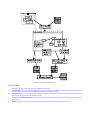
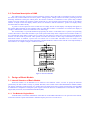
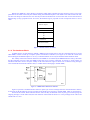
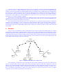
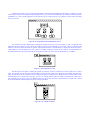
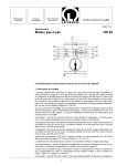
Design of AMS, an Atelier for Modeling
and Simulating Open Communication Systems
Atika COHEN and Radouane MRABET
Université Libre de Bruxelles
Service Télématique et Communication
Bd du Triomphe, CP 230 Brussels, Belgium
Tel : 322-650-57-04 Fax : 322-641-38-16
[email protected] and [email protected]
C=be; ADMD=rtt; PRMD=iihe; O=helios; S=cohen (or S=mrabet)
Abstract :
The article describes a work related to the OSISIM project (Open System Integrated
Simulator). The main objective of this project is to set up an atelier for the modelization of
communication systems and the analysis of their performances. The representation of a system to be
simulated is based on models of several standard networks available in the library which is the kernel of
the atelier. Starting with an outline of the components of the atelier, we describe the basic models to be
included in it. Moreover, a concrete example of communication system shows a methodology to be
applied when using the atelier.
1.
Introduction
The main objective of the OSISIM project is to set up an atelier for the modelization of communication systems and
the analysis of their performances. In the literature, we find the description of different toolkits dedicated to this field, such
as TOPNET [1], which is based on PROT net, a class of Petri nets; NETMOD [2], which is based on simple analytical
models; BONeS [3], which is based on block-oriented modeling paradigm, written in C++. Unlike these approaches, ours is
based on queueing networks.
Our atelier, named AMS (Atelier for Modelization and Simulation), integrates the facilities and the tools in such a
way as to be easy to use by the end-user. It gives the end-user some powerful tools to easily edit a new communication
system in a graphical environment. The AMS is based on the latest techniques in software engineering such as : graphics,
windowing, pop-up menus and the object-oriented programming paradigm. QNAP2 [4,5] (Queueing Network Analysis
Package 2) and GSS4 [6] (Graphical Support System 4)1 are the main packages that will be used to operate the AMS.
One component of this atelier is a library of basic models including most of the standard networks such as LANs
(Ethernet, Token Ring, FDDI, etc.), WANs (X25, TCP/IP), satellite and radio networks. It is obvious that the usefulness of
the atelier heavily depends on the number of available models necessary to make up transmission systems and networks.
The end-user of the AMS is not expected to be a specialist in modeling or performance analysis; however, he should
be a communication system designer. He will use the AMS to build and validate an architectural choice, or to compare
several possible ways of solving a problem.
Models have to be constructed in a very modular fashion. That is why we have to build basic models, which will
make up other models of more complex systems. Each basic model implements uniform and well-defined sets of functions,
while having clearly specified interfaces.
In the section 2, this paper describes the architectural elements of the AMS [7], and how the latter can be used. The
section 3 focuses on the design of a basic model [8], its components, the structure of messages exchanged and the
interconnection of two basic models. The section 4 is devoted to the presentation of how an end-user can build a
communication system using the atelier. Since the example selected is a complete one, it is built in a top down way. While
working out the example, we show how to decompose the system under study, how to define the environment parameters,
1These
packages are trademarks of SIMULOG, a French company specialized in the field of simulation.
i.e. those related to the modeled system, and characterizing each part of the system, and how to choose the desired
measurements. A conclusion is drawn in the last section.
2.
Outline of the atelier
2.1. Architectural elements of AMS
The main components of the AMS are shown in figure 1. On the one hand, we can find components to be handled by
the end-user such as : objects to describe a communication system to be studied (i.e. the basic models), processes to edit the
architecture and parameters of the system under study, and to generate the code modeling system. On the other hand, there
is a set of files that contain the internal representation of the system described by the end-user. Those files are to be handled
by the atelier. Hereafter, we give more explanations about those components.
2.1.1. The objects
The main objects offered to the end-user in order to describe a communication system are the Library of Basic
Models, the Graphical Database and the Scenario and Result elements.
a)
Library of Basic Models : The basic core of the AMS is constituted by a library of basic models. Each basic model,
represented by an icon in figure 1, corresponds to a communication entity such as a medium access control, protocol,
application, etc. Using these basic models, the end-user prepares the architecture of the system to be studied.
In order to facilitate carrying out these models, their interconnection and their maintenance (see section 3.1), a same
internal structure is proposed for all of them. Besides, each basic model is characterized by a definite number of
parameters. The parameter values can be edited and modified by the end-user within limits of variation associated
with each parameter.
b)
Graphical Database : This database contains all the information about icons, pop-menu and edition rules which
allow the end-user to edit his communication system graphically. This database is necessary in the edition phase, and
is not used directly by the end-user.
c)
Scenario and Result elements : These elements help the end-user to define the scenarios which will be followed
during the simulation, and the type of results the end-user wants to obtain at the end of the simulation.
2.1.2. The processes
The following processes allow the end-user, either to access the objects described above, or to generate code and
launch simulations.
a)
Editor Process : This process allows the end-user to edit his communication system graphically. To edit the
architecture, he can create several instances of basic models, connect them by links and, if necessary, he modifies the
values of some basic model parameters, in order to configure his system as he wants. The Editor generates, in a
manageable manner, the description of the edited system. This description (called Arch Descrip) is stored as a file
and can be re-used at any time, in order to re-configure the system and/or to modify its architecture. During the
edition phase, the editor verifies the validity of the architecture. For example, the connections between basic models
have to be correct; nevertheless the complete verification is fully done before the code is generated.
b)
Scenario and Result Process : This process helps the end-user to define the scenario and the type of simulation
results. A scenario is defined mainly by varying the values of some parameters called free variables. Results can be
presented in the form of charts, tables, lists or a combination of them.
c)
Generator Process: Through the description of the edited communication system and its parameters, this process
generates the Qnap2 code. Before the code generation, a complete verification will be done in order to confirm the
description provided by the end-user. The verification includes i) completeness of the architecture, namely if the
communication system architecture contains what is required for the system to function properly, ii) connectivity,
namely if all the elements (icons) created by the end-user are linked in such a manner as to avoid having two or
several portions not connected to each other.
d)
Simulator Process : This process compiles and executes the generated code. The execution depends on the scenarios
defined by the end-user. At the end of the execution, the desired results are produced, visualized and stored as
decided earlier by the end-user.
Figure 1 : Architecture of the AMS
2.1.3. The files
a)
b)
c)
d)
The following files are the important ones handled by the atelier.
Arch Descrip : This file contains the description of the communication system architecture edited by the end-user.
The description is written using the Graphical Description Language (GDL)[6].
Generated Code : It is the code of the modelization of the communication system based on the user's description.
This code is mainly written in the Qnap2 language.
Scenario and Result Description : This file contains the description of the proposed scenario and the set of desired
results types.
Results : This file contains the simulation results which are recorded according to the user's choices.
2.2. Functional description of AMS
The end-user has four processes to interact with them. Figure 2 shows the order to be followed in order to perform
the whole work, which includes the successive phases : editing systems, editing scenarios and results, generating code and
launching simulations. During the edition phase, the end-user constructs an architecture of the system using available
simple icons. Each simple icon represents a basic model such as a TCP (Transfer Control Protocol) entity or an Ethernet
network. A simple icon has one display. Besides, he has two facilities to edit the architecture : generic icon display facility
and sub-model icon edition facility.
A generic icon also represents a basic model such as a bridge, but has several displays. The display that appears in
the window edition depends on some attributes and/or on which basic model it is connected to. For instance, the display of
a bridge is different if it connects two Ethernets or two token-rings.
The second facility is a powerful mechanism proposed by the atelier. A sub-model icon is a special icon representing
a whole sub-model. A sub-model constitutes a part of the system under study and is composed of several basic models. So,
it is constructed by using either a simple icon or a generic one. For instance, a stack icon is a special icon inside which the
end-user can edit a stack of protocols. These special icons allow the end-user to edit a large communication system in a
hierarchical manner. In addition, a special icon can enclose one or several other sub-model icons. For instance, when
several local area networks are to be interconnected by a satellite backbone, each local area network can be represented by a
sub-model icon. A complete example is studied in section 4.
figure 2 : Processes call order
3.
Design of Basic Models
3.1. Internal Structure of Basic Models
Each basic model is to be detailed so as to reflect its exact behavior. Hence, we have to specify the functions
performed by the basic model as exactly as possible. Hereafter, basic models will be called Detailed Basic Models (DBM).
The primary advantages of this approach is to validate easily the model and to have accurate measurements when the DBM
is simulated as a component of a complex system. Figure 3 shows the structure of a DBM; there are three blocks : Behavior
Engine (BE), Interfaces (Int) and Measurement Block (MB).
3.1.1. The Behavior Engine Block
In the BE block, we find the modelization of the behavior of the DBM. The behavior is an open network of stations,
each station includes a queue with limited or unlimited capacity and one or several servers.
Besides, the DBM has a large number of parameters which make it flexible from the end-user's point of view. Each
parameter has an initial value set by the modeler during the modelization phase. This default value will be used if the enduser does not change it. Otherwise, the new value he provides will be taken into account. This value is to be selected from a
defined range (if any) proposed to him. Of course, the defined range is proposed in order to help him choose a correct
value.
Behavior Engine
Interface 1
Interface 2
Interface N
Measurement Block
figure 3 : Internal structure of a DBM
3.1.2. The Interfaces Block
A DBM can have several interfaces. Indeed, a DBM can not be used alone, it must be connected with one or several
other DBMs, in order to make up a complex system. The number of interfaces (N in figure 3) can either be a fixed value
known during the modelization phase or can vary so that the modeler can fix only the minimal and the maximal values.
The validity of the interconnection between several DBMs is not checked by the DBMs themselves but, by the Editor
and the Generator processes. Thus, the DBM assumes that it was correctly connected. In section 3.3, three notions are
introduced which are used to verify the validity of the interconnection. Figure 4 shows how an interface using messages
reacts with its BE and with the outside world (i.e. another interface belonging to another DBM) .
Another
DBM
I
n
t
e
r
f
a
c
e
Behavior
Engine
DBM
figure 4 : A DBM with its BE and one Interface
Figure 5 represents a standard interface with two queues. Qio receives messages from the outside which are meant to
be sent later to the BE while Qii receives messages from the BE to be sent later to another DBM which is connected to it.
Seen from the outside, all the interfaces are the same but they are different in the way they process the ingoing and
outgoing messages. On the other hand, the main function of the interfaces block is to convey messages from a BE to the
outside and vice versa.
Qii
BE
Another
DBM
Qio
figure 5 : A standard interface
3.1.3. The Measurement Block
With regard to measurements, the end-user can be satisfied with the default list of measurements presented by the
atelier. Otherwise, he can make his choices from the exhaustive list of measurements related to that particular DBM.
The measurement block contains two types of measures, the first type reflects the behavior of the DBM and thus it is
associated to the BE; the second type is associated to the interfaces and it shows mainly the data flow entering and exiting
the DBM.
All the measures are meaningful for an end-user not specialized in the field of network queueing theory. All the
aspects related to this field are transparent. The measures are associated to metrics used in the field of communication
networks.
3.2. How to construct messages for a DBM ?
As we said in the previous section, a DBM is an open network of stations, which exchange messages between
themselves and with the outside. A message is modeled as a customer which enters a station, waits in a queue before
receiving a service and finally is destroyed or transmitted to another queue. A customer may be of different types depending
on the kind of messages it models. Inside a same DBM, the modeler is free to choose the type. In contrast, if a message
transits between stations not belonging to the same DBM, the type of message has to meet a specific format. This specific
format [9] is used in order to homogenize the interactions between all DBMs.
Hereunder, the format of messages which transit between DBMs. A customer modeling such a message has the type,
named CUST_TT described in figure 6. We note that this kind of message is divided into two parts. The first one contains
data, referenced by the RFMS pointer. This data has to be transferred in a transparent manner for the intermediate DBMs.
Indeed, those DBMs do not know the structure of the data object, this structure is only known by the DBM which created it
and by the recipient DBM. The second part of the message contains control data, referenced by the RFCT pointer. The
content of this part is to be used by the DBM which receives the message. Indeed, this second part contains all the
information require for the connected DBMs to coordinate their work.
/DECLARE/
CUSTOMER OBJECT CUST_TT;
REF ANY2
RFMS;
REF ANY RFCT;
& this variable references an object carrying data.
& These data are not modified but only transferred.
& this variable references an object carrying
& control data. These data will be used by the
& DBM which receives this customer.
END;
2ANY
is a type of top level, it is the root of all the types. A pointer of this type can reference any object.
Data 1
RFMS
RFCT
Control Data 1
figure 6 : Format of message exchanged between DBMs
3.3. How to connect two DBMs ?
The exchange of messages between DBMs is done via their interfaces. For a given DBM, the interface is represented
by two stations. One station receives messages from outside, i.e. another DBM, and sends them to the BE block of this
DBM. At the opposite, the second station receives messages from the BE block of this DBM, and sends them to the outside.
This is illustrated by figure 7.
DBM1
BE1
DBM2
Int1_in
Int2_out
Int1_out
Int2_in
BE2
figure 7 : Two DBMs connected by two interfaces
Depending on the system under study, a DBM can be connected to a variety of DBMs, many instances of the same
DBM may be involved. For each connection, an interface is needed. Let us say that this DBM has several facet. If we make
an analogy with the algorithmic languages, a DBM is considered as a type. Thus several instances of a same DBM can be
created. Figure 8 shows connections (C, L) between our current DBM and two others (DBM1 and DBM2). The connections
C and L are also considered as types. In this case, we say that DBM has two facets which are DBM1 and DBM2
(Facet(DBM)={DBM1, DBM2}).
C
DBM1
DBM
L
DBM2
Figure 8 : The facets of DBM
Two other notions are going to be introduced in order to have a more flexible interconnection between DBMs. In
addition, they lead to a high degree of abstraction to validate the connections during the generation code phase. These two
notions are : superfacet and face.
A superfacet is a set of facets which offer he same service to the outside, even if they connect different DBMs to the
current one. For instance, a DBM modeling the Internet Protocol (DBM IP) can be connected to the DBM modeling
Transfer Control Protocol (DBM TCP) and the DBM modeling User Datagram Protocol (DBM UDP), thus the DBM IP has
two facets. If we consider that these two facets are the same because the service offered to IP is the same, we deduce that
they will belong to the same superfacet. On the other hand, the DBM IP can be connected also to the DBM modeling a
Logical Link Control (DBM LLC); thus the DBM IP has a third facet, but it cannot belong to the previous superfacet
because the service offered to DBM IP is different.
So, the notion of superfacet will divide the set of a DBM facets into several superfacets, each one regroups the facets
offering the same service to the outside. Some facets may remain alone, in this case we say that these particular facets
belong to the special superfacet called the zero-superfacet.
The second notion introduced in this section is the notion of face. It is exclusively used by the atelier to validate the
connectivity of an architecture. A face is composed of several superfacets and/or several facets belonging to the zerosuperfacet. The modeler defines a set of faces so that the intersection of any couple of them is the empty set. A DBM has to
be connected by all its faces to other DBMs, namely at least a superfacet or a facet of each face is used to interconnect the
current DBM.
4.
Example
In this section, we examine how to edit a communication system using the atelier. The example chosen is a complex
communication system based on satellite backbone (figure 9). This system is intended to offer communication services
through the efficient use of the satellite network. It is composed of geographically scattered "Customer Network Facilities"
(CNF) interworking through a backbone satellite which will allow direct communication paths between the earth stations
located at the CNFs. The CNF consists of a LAN connecting several workstations. The LANs could be High Speed LAN
such as FDDI or Medium Speed LANs such as Ethernet.
Satellite
Gateway
Gateway
Host
Gateway
Host
Host
Host
Host
Figure 9 : Communication system based satellite network
In the following, we illustrate how this communication system will be edited using the atelier. The edition will be
done in a top-down manner. Based on figure 8, the system can be broken down into three main components. On the one
hand, there is a satellite backbone component, and on the other hand many CNFs components, each CNF is connected via a
gateway component to the satellite. Figure 10 illustrates this first step of the edition phase. The number of CNFs is set to
three. The satellite is represented by a simple icon, and the gateway by a generic icon. Because a CNF is a complex
component, each CNF will be represented by a sub-model icon.
At this level of edition, we can specify the parameters characterizing the satellite and the gateway components. In our
model, the parameters of a satellite are the propagation time (e.g. 270 ms), the bandwidth (e.g. 2 Mbit/s) and the lost packet
probability (e.g. 10-8); and the parameters of the gateway are its storage capacity (e.g. 2 Mbytes) and its packet switching
time (e.g. 0.1 ms).
Figure 10 : Decomposition of the communication system
The second step in this edition phase is editing the content of each CNF. In our example, a CNF is composed of an
Ethernet network connecting several hosts, the number of hosts can be different for each CNF. Figure 11 illustrates the
edition of one CNF where two hosts are present. The Ethernet network is represented by a simple icon while each host is
represented by a new sub-model icon, since a host is a complex component. At this level of edition, several parameters of
the Ethernet network can be specified such as the length of its bus (e.g. 500 m) and its bandwidth (e.g. 10 Mbit/s).
Figure 11 : Decomposition of a CNF
The third step in this phase is editing the content of each host. A host is composed of a stack of protocols. To edit a
stack, the end-user chooses protocols from the library of basic models, where many protocols are available for each layer.
Thus, several stacks can be considered. In our example, the stack is composed of : a Medium Access Control (MAC) to the
Ethernet Protocol, a Logical Link Layer type 1 (LLC), an Internet Protocol (IP), a Transfer Control Protocol (TCP) and a
File Transfer protocol (FTP). Figure 12 illustrates this step where each protocol is represented by a simple icon. At this
level, the parameters characterizing each protocol can be specified.
Figure 12 : An example of a HOST
At each step, a large number of measurements can be chosen such as the throughput of each connection, a mean
delay for a file transfer, the utilization of the satellite bandwidth, and so on. These measurements can be provided for
several scenarios and pictured as charts or lists. On the other hand they can be provided periodically in time.
During the edition phase, the end-user can activate the module which in charge of verifying the coherence of the
system. Besides, information at different levels are available to assist him during this primordial phase. Once this phase is
finished, the end-user is invited, by the atelier, to save his work in a specific file; so he can modify it later. The analysis of
the system will be studied by means of other phases not described here. Nevertheless, as explained earlier, the atelier offers
the necessary tools to do this.
5.
Conclusion
This paper describes the AMS atelier which provides a set of tools for modeling and performance evaluation of
complex open communication systems. It provides a powerful human-machine interface which use the new graphics
technology. It also uses the object-oriented paradigm, namely all the basic models are designed as objects which can be
instanced several times and their behaviors can be tuned by means of parameters and their types of connectivity.
In this paper, the design of the basic model has been detailed, namely its internal structure, the interconnection
between DBMs, and the format of messages exchanged between them.
In order to clarify how to use the atelier to construct a complex model, a real communication system has been
presented and the necessary steps to edit the system have been studied.
We note that other important aspects of the atelier will be detailed in the future such as :
•
The automatic generation of interested scenarios in order to minimize the number of simulations.
•
The management of the measurements, since the atelier provides a lot of measurements which will make their postprocessing very tedious.
•
The integration of analytical models in the library.
6.
References
[1]
M. A. Marsan, G. Balbo, G. Bruno, and F. Neri, "TOPNET : A Tool for the Visual Simulation of Communication
Networks". IEEE Journal on Selected Areas in Comm., Vol. 8, no 9, 1735-1747, Dec. 90.
D. W. Bachmann, M. E. Segal, M. M. Srinivasan, and T. J. Teorey, "NetMod: A Design Tool for Large-Scale
Heterogeneous Campus Networks", IEEE Journal on Selected Areas in Comm., Vol. 9, no 1, 1735-1747, 15-24,
January 91.
K. S. Shanmugan, V. S. Frost, W. LaRue, "A block-Oriented Network Simulator", Simulation, 83-94, February 92.
"QNAP2 User's Manual", Simulog S.A. 1992.
"QNAP2 Reference Manual", Simulog S.A. 1992.
"GSS4 User's Guide", Simulog S.A. 1992.
A. Cohen and R. Mrabet, "AMS : An Integrated Simulator for Open Systems", GLOBECOM'93 Conference, 656660, Houston, Texas, November 29- December 2, 1993.
A. Cohen and R. Mrabet, "AMS : Internal structure for Basic Models", Internal Report, IIHE/HELIOS-B-115-92,
October 1992.
A. Cohen and R. Mrabet, "How to write a DBM using the QNAP2 package ?", Internal Report, STC-93-15, juin
1993.
[2]
[3]
[4]
[5]
[6]
[7]
[8]
[9]
7.
Acknowledgment
We wish to express our gratitude to SAIT Systems with whom we have been working on the OSISIM project.
Besides, we gratefully acknowledge the financial support granted by IRSIA.