1
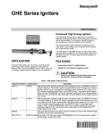
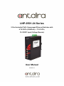
Antaira Technologies - Industrial Ethernet Switches LNP-0501-24 Series User Manual V1.0 LNP-0501-24 Series 5-Port Industrial PoE+ Unmanaged Ethernet Switches with 4*10/100Tx (30W/Port) + 1*10/100Tx, 12~36VDC Input (Voltage Booster) User Manual Version 2.0 i Antaira Technologies - Industrial Ethernet Switches LNP-0501-24 Series User Manual V2.0 © Copyright 2015 Antaira Technologies, LLC All Rights Reserved This document contains information, which is protected by copyright. Reproduction, adaptation or translation without prior permission is prohibited, except as allowed under the copyright laws. Trademark Information Antaira is a registered trademark of Antaira Technologies, LLC, Microsoft Windows and the Windows logo are the trademarks of Microsoft Corp. NetWare is the registered trademark of Novell Inc. WMM and WPA are the registered trademarks of Wi-Fi Alliance. All other brand and product names are trademarks or registered trademarks of their respective owners. Notice: Copyrights © 2015 by Antaira Technologies, LLC. All rights reserved. Reproduction, adaptation, or translation without prior permission of Antaira Technologies, LLC is prohibited, except as allowed under the copyright laws. Disclaimer Antaira Technologies, LLC provides this manual without warranty of any kind, expressed or implied, including but not limited to the implied warranties of merchantability and fitness for a particular purpose. Antaira Technologies, LLC may make improvements and/or changes to the product and/or specifications of the product described in this manual, without prior notice. Antaira Technologies, LLC will not be liable for any technical inaccuracies or typographical errors found in this guide. Changes are periodically made to the information contained herein and will be incorporated into later versions of the manual. The information contained is subject to change without prior notice. ii Antaira Technologies - Industrial Ethernet Switches LNP-0501-24 Series User Manual V2.0 FCC Notice This equipment has been tested and found to comply with the limits for a Class-A digital device, pursuant to Part 15 of the FCC rules. These limits are designed to provide reasonable protection against harmful interference in a residential installation. This equipment generates, uses, and can radiate radio frequency energy. It may cause harmful interference to radio communications if the equipment is not installed and used in accordance with the instructions. However, there is no guarantee that interference will not occur in a particular installation. If this equipment does cause harmful interference to radio or television reception, which can be determined by turning the equipment off and on, the user is encouraged to try to correct the interference by one or more of the following measures: Reorient or relocate the receiving antenna. Increase the separation between the equipment and receiver. Connect the equipment into an outlet on a circuit different from that to which the receiver is connected. Consult the dealer or an experienced radio/TV technician for help. Caution: Any changes or modifications not expressly approved by the grantee of this device could void the user's authority to operate the equipment. CE Mark Warning This is a Class-A product. In a domestic environment this product may cause radio interference in which case the user may be required to take adequate measures. Industrial Ethernet Switches Industrial Grade Unmanaged Ethernet Switches User Manual Version 2.0 (July 2015) This manual supports the following models: LNP-0501-M-24 LNP-0501-S3-24 LNP-0501-M-24-T LNP-0501-S3-24-T LNP-0501-ST-M-24 LNP-0501-ST-S3-24 LNP-0501-ST-M-24-T LNP-0501-ST-S3-24-T This document is the current official release manual. Please check our website (www.antaira.com) for any updated manual or contact us by e-mail ([email protected]). iii Antaira Technologies - Industrial Ethernet Switches LNP-0501-24 Series User Manual V2.0 Table of Contents 1.Overview ....................................................................... 1 1.1 Key Features ...................................................... 1 1.2 Package Contents .............................................. 2 1.3 Safety Precaution ............................................. 2 2.Hardware Description .................................................. 3 2.1 Physical Dimensions .......................................... 3 2.2 Front Panel ........................................................ 4 2.3 Top View ............................................................ 4 2.4 LED Indicators .................................................... 5 2.5 Ethernet Ports..................................................... 5 2.6 Cabling ............................................................... 7 2.7 Wiring the Power Inputs ..................................... 8 2.8 Wiring the Fault Alarm Contact .......................... 9 3. Mounting Installation ................................................ 10 3.1 DIN-Rail Mounting ............................................ 10 3.2 Wall Mounting ................................................... 12 4. Hardware Installation ................................................ 13 4.1 Installation Steps .............................................. 13 5. Network Application ................................................. 14 6. Trouble Shooting ....................................................... 15 7. Technical Specifications .......................................... 16 iv Antaira Technologies - Industrial Ethernet Switches LNP-0501-24 Series User Manual V1.0 1. Overview Antaira Technologies’ LNP-0501-24 series is an industrial PoE+ unmanaged Ethernet switch featuring 4*10/100Tx Fast Ethernet RJ45 ports and 1*100Fx fiber port with SC or ST type connectors and an option for multi-mode (2Km) or single-mode (30Km). Each Ethernet port supports an IEEE 802.3at high power PoE+ output up to 30W per port, making it ideal for applications that demand a PoE power source and a long distance data communication within any harsh or outdoor environment. This product series provides a low voltage input range of 12~36VDC with an internal voltage booster to support a 48VDC PoE power output. It also provides high EFT and ESD protection to prevent any unregulated voltage. The LNP-0501-24 series is IP30 rated and DIN-rail mountable. There are two wide operating temperature models for either a standard temperature range (STD: -10°C to 70°C) or an extended temperature range (EOT: -40°C to 75°C). It also provides Ethernet connectivity with PoE functions and a fiber connection for mobile surveillance applications utilizing a low voltage power source as a battery, and for any other industrial automation field sites needing a 24VDC power source, such as, security surveillance, traffic monitoring systems, oil/gas and mining, facility management for power/utility, water wastewater treatment plants, and lastly, automated production lines in factory automation. 1.1 Key Features System Interface/Performance All RJ-45 ports support the auto MDI/MDI-X function Embedded 4*10/100Tx (PSE 30W/Port), 1*100Fx SC/ST type connector (Multi-mode 2Km, or Single-mode 30Km) Store-and-forward switching architecture 2K MAC address table Power line EFT protection: 2,000VDC; Ethernet ESD protection: 6,000VDC Power Input DC 12~36V (voltage booster) redundant power, with a 6-pin removal terminal block Operating Temperature Standard operating temperature model: -10°C ~ 70°C Extended operating temperature model (–T): -40°C ~ 75°C 1 Antaira Technologies - Industrial Ethernet Switches LNP-0501-24 Series User Manual V2.0 Case/Installation IP-30 protection DIN-Rail and wall mount design 1.2 Package Contents 1 - LNP-0501-24 (T): 5-port industrial PoE+ unmanaged Ethernet switch with 4*10/100Tx (30W/port), 1*100Fx Fiber SC/ST type connector (Multi-mode 2Km, or Single-mode 30Km); 12~36VDC (voltage booster) 1 - User manual 1 - Product CD 2 - Wall mounting brackets and screws 1 - DC cable –18 AWG & DC jack 5.5x2.1mm 1.3 Safety Precaution Attention: If the DC voltage is supplied by an external circuit, please use a protection device on the power supply input. The industrial Ethernet switch’s hardware specs, ports, cabling information, and wiring installation will be described within this user manual. 2 Antaira Technologies - Industrial Ethernet Switches LNP-0501-24 Series User Manual V2.0 2. Hardware Description 2.1 Physical Dimensions Figure 2.1, below, shows the physical dimensions of Antaira Technologies’ LNP-0501-24 series: 5port industrial PoE+ unmanaged Ethernet switch with 4*10/100Tx (30W/port), 1*100Fx fiber SC/ST type connector (Multi-mode 2Km, or Single-mode 30Km); 12~36VDC (voltage booster). (W x D x H) is 46mm x 99mm x 142mm Figure 2.1 LNP-0501-24 Series Physical Dimensions 3 Antaira Technologies - Industrial Ethernet Switches LNP-0501-24 Series User Manual V2.0 2.2 Front Panel The front panel of the LNP-0501-24 series: 5-port industrial PoE+ unmanaged Ethernet switch with 4*10/100Tx (30W/port), 1*100Fx fiber SC/ST type connector (Multi-mode 2Km, or Single-mode 30Km); 12~36VDC (voltage booster) is shown below in Figure 2.2. 6-Pin Removal Terminal Block (Power Input) Grounding Screw LED for PWR1, PWR2, and Fault Fiber Port #5 – 100Fx (Tx/Rx) LED for Fiber Port Status LED for 100MB network speed status LAN Port (1~4) 10/100Tx LED for 10MB network speed Status LED for PoE Status Figure 2.2 - Front Panel of the LNP-0501-24 Series 2.3 Top View Figure 2.3, below, shows the top panel of the LNP-0501-24 series switch that is equipped with one 6-pin removal terminal block connector for dual DC power inputs (12~36 VDC). Figure 2.3 Top Panel View of LNP-0501-24 Series 4 Antaira Technologies - Industrial Ethernet Switches LNP-0501-24 Series User Manual V2.0 2.4 LED Indicators There are LED light indicators located on the front panel of the industrial Ethernet switch that display the power status and network status. Each LED indicator has a different color and has its own specific meaning, see below in Table 2.1. LED Color P1 Green P2 On Power input 1 is active Off Power input 1 is inactive On Power input 2 is active Off Power input 2 is inactive On Power input 1 or 2 is inactive Off Power input 1 and 2 are both functional, or no power inputs Green Fault PoE Indicators (Port 1~4) Description Red Off The port is supplying PoE power No powered-devicepowered-device attached or power supplying fails On Connected to network, 100Mbps On Green Green LAN Port 1 ~ 4 (Upper LED) Flashing Green LAN Port 1 ~ 4 (Lower LED) Fiber Port Off Not connected to network On Connected to network, 10Mbps Flashing Green Networking is active Networking is active Off Not connected to network On Connected to network, 100Mbps Flashing Off Networking is active Not connected to network Table 2.1 LED Indicators for LNP-0501-24 Series 2.5 Ethernet Ports RJ-45 Ports RJ-45 Ports (Auto MDI/MDIX): The RJ-45 ports (LAN 1~4) are auto-sensing for 10Base-T, or 100Base-Tx devices connections. Auto MDI/MDIX means that the switch can connect to another switch or workstation without changing the straight-through or crossover cabling. See the figures shown below for the straight-through and crossover cabling schematics. 5 Antaira Technologies - Industrial Ethernet Switches LNP-0501-24 Series User Manual V2.0 RJ-45 Pin Assignments (Table 2.2) Pin Number Assignment 1 Rx+ 2 Rx- 3 Tx+ 6 TxTable 2.2 RJ45 Pin Assignments Note: The “+” and “-” signs represent the polarity of the wires that make up each wire pair. All ports on this industrial Ethernet switch support automatic MDI/MDI-X operations. Users can use straight-through cables (see figure below) for all network connections to PCs, servers, and other switches or hubs. With straight-through cable, pins 1, 2, 3, and 6, at one end of the cable, are connected straight through to pins 1, 2, 3 and 6 at the other end of the cable. The table below (Table 2.3) shows the 10BASE-T/100BASE-TX/1000BASE-T MDI and MDI-X port pin outs. Pin MDI-X Signal Name MDI Signal Name 1 Receive Data plus (RD+) Transmit Data plus (TD+) 2 Receive Data minus (RD-) Transmit Data minus (TD-) 3 Transmit Data plus (TD+) Receive Data plus (RD+) 6 Transmit Data minus (TD-) Receive Data minus (RD-) Table 2.3 Ethernet Signal Pin Outs The following figures show the cabling schematics for straight-through and crossover cables. Figure 2.4 - Straight-Through Cables Schematic Figure 2.5 - Crossover Cables Schematic 6 Antaira Technologies - Industrial Ethernet Switches LNP-0501-24 Series User Manual V2.0 Fiber Port The fiber port of the SC type connector can work in multi-mode or single-mode. When connecting the fiber port to another one, please connect accordingly following the figure below. The wrong connection will cause the port to not work normally. Figure 2.6 – Fiber Port Cabling ***ATTENTION This is a Class 1 Laser/LED product. Don’t stare into the Laser/LED beam. 2.6 Cabling Twisted-pair segments can be connected with an unshielded twisted pair (UTP) or shielded twisted pair (STP) cable. The cable must comply with the IEEE 802.3u 100Base TX standard (e.g. Category 5, 5e, or 6). The cable between the equipment and the link partner (switch, hub, workstation, etc.) must be less than 100 meters (328 ft.) long. Fiber segment using single-mode connector type must use 9/125μm single-mode fiber cable. Fiber segment using multi-mode connector type must use 50 or 62.5/125 μm multi-mode fiber cable. 7 Antaira Technologies - Industrial Ethernet Switches LNP-0501-24 Series User Manual V2.0 2.7 Wiring the Power Inputs Please follow the steps below to insert the power wire. 1. Insert the positive and negative wires into the PWR1 (V1+, V1-) and PWR2 (V2+, V2-) contacts on the terminal block connector as shown below in Figure 2.7. Figure 2.7 Power Terminal Block 2. Tighten the wire-clamp screws to prevent the wires from loosening, as shown below in Figure 2.8. Figure 2.8 Power Terminal Block **Note: Only use copper conductors, 60/75°C, tighten to 5 lbs. The wire gauge for the terminal block should range between 18~20 AWG. 8 Antaira Technologies - Industrial Ethernet Switches LNP-0501-24 Series User Manual V2.0 2.8 Wiring the Fault Alarm Contact The fault alarm contact is in the middle of the terminal block connector as the picture shows below in Figure 2.9. By inserting the wires, it will detect the fault status including power failure or port link failure (managed industrial switch only) and form a normal open circuit. An example is shown below in Figure 2.9. Figure 2.9 Wiring the Fault Alarm Contact **Note: The wire gauge for the terminal block should range between 12 ~ 24 AWG. If only using one power source, jumper Pin 1 to Pin 5 and Pin 2 to Pin 6 to eliminate power fault alarm. 9 Antaira Technologies - Industrial Ethernet Switches LNP-0501-24 Series User Manual V2.0 3. Mounting Installation 3.1 DIN-Rail Mounting The DIN-Rail is pre-installed on the industrial Ethernet switch from the factory. If the DIN-Rail is not on the industrial Ethernet switch, please refer to Figure 3.1 to learn how to install the DIN-Rail on the switch. Figure 3.1 The Rear Side of the Switch and DIN-Rail Bracket 10 Antaira Technologies - Industrial Ethernet Switches LNP-0501-24 Series User Manual V2.0 Follow the steps below to learn how to hang the industrial Ethernet switch. 1. Use the screws to install the DIN-Rail bracket on the rear side of the industrial Ethernet switch. 2. To remove the DIN-Rail bracket, do the opposite from step 1. 3. After the DIN-Rail bracket is installed on the rear side of the switch, insert the top of the DINRail on to the track as shown below in Figure 3.2. Figure 3.2 Insert the Switch on the DIN-Rail 4. Lightly pull down the bracket on to the rail as shown below in Figure 3.3. Figure 3.3 Stable the Switch on DIN-Rail 5. Check if the bracket is mounted tightly on the rail. 6. To remove the industrial Ethernet switch from the rail, do the opposite from the above steps. 11 Antaira Technologies - Industrial Ethernet Switches LNP-0501-24 Series User Manual V2.0 3.2 Wall Mounting Follow the steps below to mount the industrial Ethernet switch using the wall mounting bracket as shown below in Figure 3.4. 1. Remove the DIN-Rail bracket from the industrial Ethernet switch by loosening the screws. 2. Place the wall mounting brackets on the top and bottom of the industrial Ethernet switch. 3. Use the screws to screw the wall mounting bracket on the industrial Ethernet switch. 4. Use the hook holes at the corners of the wall mounting bracket to hang the industrial Ethernet switch on the wall. 5. To remove the wall mount bracket, do the opposite from the steps above. Figure 3.4 Remove DIN-Rail Bracket from the Switch Below, in Figure 3.5 are the dimensions of the wall mounting bracket. Figure 3.5 Wall Mounting Bracket Dimensions 12 Antaira Technologies - Industrial Ethernet Switches LNP-0501-24 Series User Manual V2.0 4. Hardware Installation 4.1 Installation Steps This section will explain how to install Antaira Technologies’ LNP-0501-24 (T): 5-port industrial PoE+ unmanaged Ethernet switch with 4*10/100Tx (30W/port), 1*100Fx Fiber SC/ST type connector (Multi-mode 2Km, or Single-mode 30Km); 12~36VDC (voltage booster). Installation Steps 1. Unpack the industrial Ethernet switch from the original packing box. 2. Check if the DIN-Rail bracket is screwed on the industrial Ethernet switch. If the DIN-Rail is not screwed on the industrial Ethernet switch, please refer to the DINRail Mounting section for DIN-Rail installation. If there’s requiring to wall mount the industrial Ethernet switch, please refer to the Wall Mounting section for wall mounting installation. 3. To hang the industrial Ethernet switch on a DIN-Rail or wall, please refer to the Mounting Installation section. 4. Power on the industrial Ethernet switch and then the power LED light will turn on. For the help on how to wire power, please refer to the Wiring the Power Inputs section. Please refer to the LED Indicators section for LED light indication. 5. Prepare the twisted-pair, straight-through category 5 cable for Ethernet connection. 6. Insert one side of the RJ-45 cable into switch’s Ethernet port and on the other side into the networking device’s Ethernet port, e.g. switch PC or server. The Ethernet port’s (RJ-45) LED on the industrial Ethernet switch will turn on when the cable is connected to the networking device. Please refer to the LED Indicators section for LED light indication. 7. When all connections are set and the LED lights all show normal, the installation is complete. 13 Antaira Technologies - Industrial Ethernet Switches LNP-0501-24 Series User Manual V2.0 5. Network Application This segment provides an example of an industrial Ethernet switch application (Figure 5.1). Figure 5.1 Industrial PoE Ethernet Switch Application Reference 14 Antaira Technologies - Industrial Ethernet Switches LNP-0501-24 Series User Manual V2.0 6. Trouble Shooting Always verify to have the right power cord or adapter. Never use a power supply or adapter with a non-compliant DC output voltage or it will burn the equipment. Select the proper UTP or STP cable in order to construct the network. Use an unshielded twisted-pair (UTP) or shield twisted-pair (STP) cable for RJ-45 connections: 100Ω Category 5e for 10M/100Mbps. Also be sure that the length of any twisted-pair connection does not exceed 100 meters (328 feet). Diagnosing LED Indicators: To assist in identifying problems, the switch can be easily monitored with the LED indicators which help to identity if any problems exist. o Please refer to the LED Indicators section for LED light indication. If the power indicator LED does not turn on when the power cord is plugged in, the user may have a problem with the power cord. Check for loose power connections, power losses or surges at the power outlet. o Please contact Antaira for technical support service, if the problem still cannot be resolved. If the industrial switch LED indicators are normal and the connected cables are correct but the packets still cannot transmit, please check the system’s Ethernet devices’ configuration or status. 15 Antaira Technologies - Industrial Ethernet Switches LNP-0501-24 Series User Manual V2.0 7. Technical Specifications Table 7.1 has the technical specifications for Antaira Technologies’ LNP-0501-24 series: 5-port industrial PoE+ unmanaged Ethernet switch with 4*10/100Tx (30W/port), 1*100Fx Fiber SC/ST type connector (Multi-mode 2Km, or Single-mode 30Km); 12~36VDC (voltage booster). IEEE 802.3 10Base-T Ethernet Standard IEEE 802.3u 100Base-TX Fast Ethernet IEEE802.3x Flow Control and Back Pressure IEEE802.3at Power over Ethernet Protocol Transfer Rate CSMA/CD 14,880pps for Ethernet port 148,800pps for Fast Ethernet port Up to 100M for each Fast Ethernet port Transmission Distance Up to 2Km for Multi-mode Fiber port; or Up to 30Km for Single-mode Fiber port. MAC Address RJ45 (Ethernet) Port 2K Table Size 4*10/100Tx (30W/Port) auto negotiation speed, full/half duplex mode, and auto MDI/MDI-X connection RJ-45 port #1 ~ # 4 support IEEE 802.3at end-point, alternative A mode. PoE Pin Assignment Positive (VCC+): Pin 1, 2 Negative (VCC-): RJ-45 pin 3, 6 Data: Pin 1, 2, 3, 6 Fiber Port 1*100Fx SC/ST type connector: Multi-mode (2Km) or Single-mode (30Km) Per unit: Power1(Green), Power2(Green), Fault(Red) LED Per port: Link/Activity (Green) PoE: Feeding Power (Green) 10BaseT: 2-pair UTP/STP Cat. 3, 4, 5 cable Network Cable EIA/TIA-568 100-ohm (100m) 100BaseTX: 2-pair UTP/STP Cat. 5 cable EIA/TIA-568 100-ohm (100m) Over Current Protection Power Input Single-Blown Fuse Redundant power DC 12~36 with connective 1*6-pin removable terminal block 16 Antaira Technologies - Industrial Ethernet Switches LNP-0501-24 Series User Manual V2.0 Fault Output 1 Relay output Max Power Consumption 145 Watts (Full load with PoE function) Installation DIN-Rail mounting, wall mounting (optional) Operating Temperature o o o o Standard: -10 C to 70 C (14° to 158° F) EOT: -40 C to 75 C (-40° to 167° F) Operating Humidity 5% to 95% (Non-Condensing) Storage Temperature -40 C to 85 C Case Dimension IP-30, 46mm (W) x 99mm (D) x 142mm (H) o o (-40°F ~ 185°F) FCC Class A EMI IEC61000-4-2/3/4/5/6/8 IEC61000-6-2 IEC61000-6-4 IEC60068-2-32 (Free fall) Stability Testing IEC60068-2-27 (Shock) IEC60068-2-6 (Vibration) Safety UL 508 Table 7.1 LNP-0501-24 Series Technical Specifications Antaira Customer Service and Support (Antaira US Headquarter) + 844-268-2472 (Antaira Europe Office) + 48-22-862-88-81 (Antaira Asia Office) + 886-2-2218-9733 Please report any problems to Antaira: www.antaira.com / [email protected] www.antaira.eu / [email protected] www.antaira.com.tw / [email protected] Any changes to this material will be announced on the Antaira website. 17