1
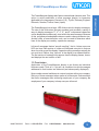
P3000 PowerMarquee
Master Display
Hardware User Manual
(Manual Part Number MAN-P3000-003)
WARNING!
Programmable control devices such as UTICOR’s P3000 PowerMarquee Master, must not be
used as stand-alone protection in any application. Unless proper safeguards are used, unwanted
start-ups could result in equipment damage or personal injury. The operator must be made aware
of this hazard and appropriate precautions must be taken.
In addition, consideration must be given to the use of an emergency stop function that is independent of the programmable controller.
The diagrams and examples in this user manual are included for illustrative purposes only. The
manufacturer cannot assume responsibility or liability for actual use based on the diagrams and
examples.
Trademarks
This publication may contain references to products produced and/or offered by other companies.
The product and company names may be trademarked and are the sole property of their respective
owners. UTICOR Technology, L. P. disclaims any proprietary interest in the marks and names of
others.
Manual P/N MAN-P3000-003
© Copyright 2003, UTICOR Technology, L.P.
All Rights Reserved
No part of this manual shall be copied, reproduced, or transmitted in any way without the prior
written consent of UTICOR Technology, L.P. UTICOR Technology, L.P. retains the exclusive rights
to all information included in this document.
MANUFACTURED and MARKETED
by
UTICOR TECHNOLOGY, L. P.
4140 Utica Ridge Rd. • Bettendorf, IA 52722-1327
Phone: 1-563-359-7501 • Fax: 1-563-359-9094 • www.UTICOR.net
P3000 PowerMarquee Master
CHAPTER 1. INTRODUCTION
Manual Organization
................................................................................................... 2
Manual Overview
................................................................................................... 3
Need HELP?
................................................................................................... 3
1.0
Introduction to the P3000 PowerMarquee Master ................................................... 4
1.1
Physical Characteristics ........................................................................................... 4
1.2
Messages
................................................................................................... 4
1.3
Conclusion
................................................................................................... 5
1.4
Specifications
................................................................................................... 6
CHAPTER 2. UNIT HARDWARE
2.0
Introduction to the P3000 PowerMarquee Hardware ............................................. 10
2.1
Interfacing
................................................................................................. 10
2.1.1
Power Input Terminals ............................................................................. 10
2.1.2
RS-422A Serial/Repeater Port ................................................................ 11
2.2
DIP Switches
................................................................................................. 13
2.2.1 Switch Two — Changing Character Sets ...................................................... 13
2.3
Changing from 115 VAC to 230 VAC Input Power • Changing the Fuse ............... 14
2.4
Conclusion
................................................................................................. 14
CHAPTER 3. POWERPANEL CONTROL UNIT
3.1
Introduction
................................................................................................. 16
3.2
PLC Port
................................................................................................. 17
3.3
COM1 Port
................................................................................................. 18
CHAPTER 4. OUTLINE DIMENSIONS
Outline Dimensions
............................................................................................... A-2
INDEX
MAN-P3000-003
................................................................................................ I-1
Phone: 1-563-359-7501 • Fax: 1-563-359-9094 • www.uticor.net
i
Introduction
Warning/Trademarks/Copyright ...................................................................... (inside front cover)
Table of Contents
.................................................................................................... i
P3000 PowerMarquee Master
This page intentionally left blank.
ii
Phone: 1-563-359-7501 • Fax: 1-563-359-9094 • www.uticor.net
MAN-P3000-003
Introduction
1
In this chapter....
— Manual Organization
— Manual Overview
— Need HELP?
— Introduction to the P3000 PowerMarquee Master
— Specifications
P3000 PowerMarquee Master
Introduction
Manual Organization
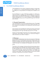
The P3000 PowerMarquee Master Hardware User Manual is arranged in chapters. A description of
key information contained in each chapter is provided below.
Chapter
2
Description
1
Introduction
This chapter introduces you to the manual organization and overview. Information
is provided on how to find help with installation of the hardware and programming.
Also provided is an introduction to the P3000 PowerMarquee Master, its physical
characteristics, and messages. Specifications for the various models of the
PowerMarquee Master are provided on page 7 of this chapter.
2
Unit Hardware
This chapter provides information on the P3000 PowerMarquee Master Hardware.
Included are sections on DIP Switches, Changing Input Power from 115VAC to
230VAC, and Changing the Fuse. Control board features and settings are discussed, as well as accessing the board.
3
PowerPanel Control Unit
In this chapter you will find information on the PowerPanel Control Unit that is
inside the PowerMarquee Master. Provided is information on the PLC Port — the
PLC connector pinout and a list of PLC cable part numbers. Also shown are COM1
Port connections to a programming computer or RS-232C/RS-422A connections.
4
Outline Dimensions
The chapter includes outline dimension drawing for the two P3000 PowerMarquee
model sizes.
A
Appendix A
This chapter includes PLC to PowerPanel Control Unit Connector wiring diagrams
for compatible PLCs and information about the option boards that are factory
installed and allow connectivity to certain PLCs or networks.
Phone: 1-563-359-7501 • Fax: 1-563-359-9094 • www.uticor.net
MAN-P3000-003
P3000 PowerMarquee Master
Manual Overview
PowerMarquee
User Manual
This manual, the P3000 PowerMarquee Master Hardware User Manual,
P/N MAN-P3000-003, and the PowerMarquee Programming Software User
Manual, P/N MAN-P3000-002 will take you through the steps necessary
to get your PowerMarquee up and running in the shortest possible time.
Although your familiarity with programmable message display devices
will determine how quickly you move through the steps — we’ve provided
you with easy, step-by-step instructions.
Need HELP?
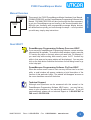
PowerMarquee Programming Software Onscreen HELP
If you are using PowerMarquee Programming Software, context sensitive
onscreen help is available. To access the Help windows, simply press the
F1 function key while on the topic where you need help. For example, if
you need help while working with screens, press the F1 function key
while in that area and a popup window will be displayed. You may also
click on the Help button located at the bottom of most dialog boxes to go
to the help topic.
PowerMarquee Programming Software Fly-Over HELP
When the mouse cursor comes to rest over any tool bar item for a short
while, a small window will appear containing a brief description of the
function of that particular button. The window will disappear as soon as
the cursor has been moved off the button.
Technical Support
Although most questions can be answered with this manual or the
PowerMarquee Programming Software HELP topics, you may find answers to your questions on our web site @ www.uticor.net. If you still
need assistance, please call our technical support at 1-800-832-3647 or
FAX us at 1-563-359-9094.
MAN-P3000-003
Phone: 1-563-359-7501 • Fax: 1-563-359-9094 • www.uticor.net
3
Introduction
Introduction
P3000 Marquee
User Manual
P3000 PowerMarquee Master
Introduction
1.0
The P3000 PowerMarquee Master
The PowerMarquee is a cost-efficient, alphanumeric display. It is the newest
of UTICOR’s line of Programmable Message Displays (PMD) The
PowerMarquee is a large-character LED display that is available in two
sizes.
The PowerMarquee is a large LED display available in 2 widths and 1
height for a total of 2 different sizes. The PowerMarquee is a red LED
(also available in High-Bright Red LED display — see page 7) display that
displays messages in 2", 4", 6", and 8" characters. The PowerMarquee
uses suspended mounting: the unit is suspended using a hole in the top of
each end plate.
1.1 Physical Characteristics
The PowerMarquee is housed in an anodized aluminum case. Two capped
holes are provided for routing wires through the back access plate. The
fuse, connectors, and switches can be accessed by removing the back
access plate.
The front panel of the PowerMarquee contains a lens that covers the LED
field and protects the inside of the unit. The LED field is offered in 2 sizes.
The display area is 9.6" high. Field width sizes are 36" or 72" wide.
Chapter 2 provides hardware information for the marquee displays. Wiring
requirements, switch settings, fuse locations, etc. are found in Chapter 2.
Outline dimensions are located in Chapter 4.
1.2 Messages
How messages look depend on the way they were programmed. Messages
programmed into the PowerMarquee master have message options that
determine message outputs and visual appearance. One of the master
message output options is sending messages to slaves. When the message
contains this option, the message can be displayed on one, some, or all
slaves.
The behavior of the message is determined by selected message options
and/or embedded codes. Messages can be stationary, flashing, or scrolling.
Scrolled messages scroll up or left. Other options determine if message
text is centered on lines, if previous text remains on the display or is
removed, etc. Embedded codes place time, date, and variable data
locations in the message. These locations display the continuously-updated
information it receives from the controller or computer.
4
Phone: 1-563-359-7501 • Fax: 1-563-359-9094 • www.uticor.net
MAN-P3000-003
P3000 PowerMarquee Master
The PowerMarquee has a large, LED field on which to display messages.
The size of this field varies (see part numbers) and provides a variety of
ways to display messages. 2", 4", 6", 8", and 8” compressed characters
can be displayed simultaneously, even within the same message. Because
of this, programmed embedded codes are used to change character size.
Another code, a frame definition code, can be used to determine which
lines of the display are used by a particular message.
Left-scroll messages feature “smooth scrolling”, that is, letters move one
LED at a time. Each portion of a letter will illuminate every dot in that row
when it scrolls across the display. Upward-scrolling messages actually do
not scroll at all. Rather, they “wipe on” to the display in an upward fashion.
The first section of message lines appear, then the display pauses, clears,
and displays the next section of text.
1.3 Conclusion
Application of the PowerMarquee display is as diverse as individual
business needs. Think of it, if you will, as a mailbox into which messages
addressed to that location are delivered (and subsequently displayed).
Now consider several mailboxes in various locations within your company.
Delivery of these messages take a matter of milliseconds. And remember
that these messages were written by employees of your company for
employees of your company to keep everyone informed.
MAN-P3000-003
Phone: 1-563-359-7501 • Fax: 1-563-359-9094 • www.uticor.net
5
Introduction
Introduction
The PowerMarquee displays also feature international character sets. This
option is switch-selectable to allow message display in characters
applicable to the languages of America (U.S.), Cyrillic, Germany, England,
Denmark, Sweden, France, Kana (Japan)
P3000 PowerMarquee Master
Introduction
1.4 Specifications
POWER REQUIREMENTS:
OPERATING TEMPERATURE:
115/230 VAC (102-132)(194-250) 47-63 Hz
(Jumper Selected — see 2.6)
1W4H: 130 VA
2W4H: 250 VA
0 to 60 ºC (0 to 140 ºF) Ambient
STORAGE TEMPERATURE:
–40 to +95 ºC (–40 to +203 ºF) Ambient
HUMIDITY:
0-95% RH Noncondensing
ELECTRICAL
INTERFERENCE TOLERANCE:
FUSE TYPE:
NEMA ICS 2-230 Showering Arc Test , ANSI C37.90a-1974
(SWC) Surge Withstand Capability Test
1W4H:
2W4H:
115 VAC: 1.5 Amp
230 VAC: 1.0 Amp
115 VAC: 3.0 Amp
230 VAC: 2.0 Amp
@
@
@
@
250
250
250
250
V
V
V
V
2AG Subminiature Slo-Blo, 5 mm x 15 mm (.177" x .580")
OVERALL DISPLAY:
2", 4", 6", 8", or 8" compressed Red LED Characters
5 x 7 Dot Matrix — 50.8 mm (2") High Characters
10 x 14 Dot Matrix — 101.6 (4") High Characters
15 x 21 Dot Matrix — 152.4 (6") High Characters
20 x 28 Dot Matrix — 203.2 (8") High Characters
10 x 28 Dot Matrix — 203.2 (8") High Characters
CHARACTER SET:
All Standard ASCII Upper/Lower Case and Symbols
INTERNATIONAL
CHARACTER SETS:
American (U.S.), Cyrillic, Germany, England, Denmark, Sweden,
France, Kana (Japan)
SPACE REQUIREMENTS:
Dependent upon unit size (see Appendix A)
HOUSING:
Extruded and Flat Plate Aluminum
WEIGHT:
1W4H: 37 lbs.
2W4H: 73 lbs.
CONNECTORS:
Power Input: 3 Wire-Clamp Screws for 12-18 AWG
Serial/Repeater Port: 11 Wire-Clamp Screws for 18-22 AWG
PowerPanel Connector: D-SUBS
Option Board Connector: (Depends upon type of Option Board)
Continued on next page —
6
Phone: 1-563-359-7501 • Fax: 1-563-359-9094 • www.uticor.net
MAN-P3000-003
P3000 PowerMarquee Master
PART NUMBER:
1 (Width):
1 = 1 Wide
2 = 2 Wide
2 (Height):
4 = 4 High
3 (Future):
0 = None
4 (Color):
0 = Red
1 = High Bright Red
5 (Master):
0 = Master
6 (Memory):
2= 512K
3=1Meg
7 (Interfaces):
0= Serial Interfaces (Drivers)
1= Allen-Bradley
2 =Modbus Plus
5=Devcenet
6=Controlnet
7=Ethenet 10Mhz
8=Profibus
9=Ethernet IP 100Mhz
Phone: 1-563-359-7501 • Fax: 1-563-359-9094 • www.uticor.net
Introduction
Introduction
MAN-P3000-003
UPM- X W X X H - X X 0 X X
1
2
3 4 5 6 7
7
Introduction
P3000 PowerMarquee Master
This page intentionally left blank
8
Phone: 1-563-359-7501 • Fax: 1-563-359-9094 • www.uticor.net
MAN-P3000-003
Unit Hardware
In this chapter....
— Interfacing
— Power Input Terminals
— RS-422A Serial/Repeater Port
— RS-232C Port
— DIP Switches
— Changing from 115 VAC to 230 VAC Input
Power • Changing the Fuse
2
P3000 PowerMarquee Master
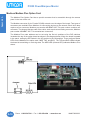
INTRODUCTION TO P3000 POWERMARQUEE HARDWARE
Unit Hardware
2. 0
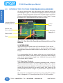
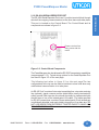
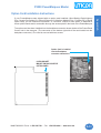
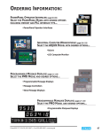
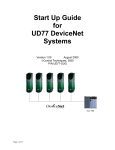
All wiring terminations and adjustments are located inside the
PowerMarquee. Figure 2-1 shows the PowerMarquee with the access plate
removed. General components referenced in following chapter are labeled.
Please note that PowerMarquee display comes in 2 sizes. Figure 2-1 shows
the smaller unit. The access area is the same on all units.
11-position RS-422A
Serial/Repeater Port
Control
Board
Switches SW1,
SW2, and SW3
3 Wire-Clamp
Screw Power
Terminal
Power Jumpers
Fuse
Figure 2-1. Back View of the PowerMarquee Display with Access Plate
Removed
2.1 INTERFACING
Terminal blocks are located inside the PowerMarquee. There are two
7/8"holes drilled in the access plate to accommodate routing the
communication and power cables in and out of the cabinet (for 1/2" conduit
fittings).
It is recommended that the power cables are not routed with the
communication cables to reduce the chance of the power cables inducing
noise into the communication signal lines. Additional holes can be drilled
in the access plate if needed.
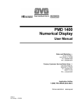
2.1.1 Power Input Terminals
Three terminals are provided for connecting operating power to the unit.
These terminals are located on the Control Board (see figure 2-1, above).
Power Input terminals are labeled L1, L2, and chassis ground (///). Always
connect the ground terminal to the safety ground. Also located on the
Control Board (and shown on figure 2-1) are the Power Jumpers and the
Fuse.
The marquees are shipped from the factory set for 115 VAC operation.
Refer to paragraph 2.4 to reconfigure the unit for 230 VAC operation.
10
Phone: 1-563-359-7501 • Fax: 1-563-359-9094 • www.uticor.net
MAN-P3000-003
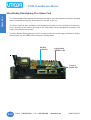
P3000 PowerMarquee Master
Please note that fuse
rating varies with the
model
Figure 2-2. Control Board Components
The PowerMarquee also has alternative RS-232C transmission capabilities
(see paragraph 2.1.3). Typical wiring options for the Serial/Repeater Port
are found in figure 2-3 on the next page.
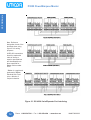
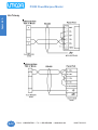
The following text refers to figure 2.3 on the next page.The two
configurations at the top can be used to interface to slave units when only
unidirectional communication is to take place.
An RS-422 “link” consists of a two-wire transmitting line, a two-wire receiving
line (optional), signal common and the shield that is usually terminated to
safety ground. Each two-wire line should physically be implemented with
the two wires of one of the twisted pairs in the cable. (The cable specified
for RS-422 connections consists of three twisted pairs.) Each twisted pair
is individually shielded, and each shield is brought out to a drain wire. DO
NOT USE WIRES FROM DIFFERENT TWISTED PAIRS TO MAKE UP A
TWO-WIRE SIGNAL LINE.
MAN-P3000-003
Phone: 1-563-359-7501 • Fax: 1-563-359-9094 • www.uticor.net
11
Unit Hardware
Introduction
2.1.2 RS-422A SERIAL/REPEATER PORT
The RS-422A Serial/Repeater Port is an 11-position terminal block through
which all the outgoing communications to the other slave units take place.
This port is located on the Control Board. The Control Board and its
components are shown in figure 2-2.
Unit Hardware
P3000 PowerMarquee Master
Note: Reference
designation levels of the
terminals when using
figure 2-3 for wiring
purposes.
All RS-422 connections
should be made with
cable of similar or
superior specifications
and characteristics to
those specified for *
Belden cable number
9730.
* Belden is a registered
trademark of Belden
Electrical Wire Products, a division of
Cooper Industries.
Figure 2.3 RS-422A Serial/Repeater Port Interfacing
12
Phone: 1-563-359-7501 • Fax: 1-563-359-9094 • www.uticor.net
MAN-P3000-003
P3000 PowerMarquee Master
Unit Hardware
Introduction
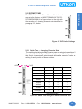
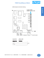
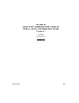
2.2 DIP SWITCHES
The DIP Switches on the PowerMarquee Control board
are set at the factory and MUST REMAIN IN THE POSITIONS SHOWN in the figure shown to the right with
the exception of changing character sets described in
paragraph 2.3, below.
Figure 2.4 DIP Switch Settings
2.2.1 Switch Two — Changing Character Sets
The switch selectable extended character sets are selected on positions 2
through 4 of Switch 2. Figure 2-5 shows the location of Switch 2 positions
that control character set selection and defines the numerical value or
setting for each position of these switches.
OPEN
CLOSE
Character Set
SW2-2
SW2-3
SW2-4
America (U.S.)*
0
0
0
Cyrillic
1
0
0
France
0
1
0
Germany
1
1
0
England
0
0
1
Denmark
1
0
1
Sweden
0
1
1
Kana (Japan)
1
1
1
* Default Factory Setting
Figure 2.5 Switch Two Settings to Define Character Sets
MAN-P3000-003
Phone: 1-563-359-7501 • Fax: 1-563-359-9094 • www.uticor.net
13
P3000 PowerMarquee Master
Unit Hardware
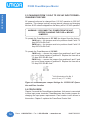
2.3 CHANGING FROM 115 VAC TO 230 VAC INPUT POWER •
CHANGING THE FUSE
AC powered units can be changed from 115 VAC operation to 230 VAC
operation. This change involves moving internal jumpers and changing
the fuse. All AC units are shipped from the factory set for 115 VAC operation.
WARNING!! DISCONNECT AC POWER FROM THE UNIT
BEFORE CHANGING THE FUSE or MOVING
JUMPERS!!
To operate the PowerMarquee at 115 VAC (as shipped from the factory):
1W4H units — the jumpers must be in positions A and C with 1.5
Amp 250V Slo-Blo fuse*.
2W4H units — the jumpers must be in positions A and C with 3.0
Amp 250V Slo-Blo fuse*.
To operate the PowerMarquee at 230 VAC:
1W4H units — remove the jumpers from positions A and C and
put one of these jumpers in position B. Replace the fuse with a
1.0 Amp 250V Slo-Blo fuse*.
2W4H units — remove the jumpers from positions A and C and
put one of these jumpers in position B. Replace the fuse with a
2.0 Amp 250V Slo-Blo fuse*.
* 2AG Subminiature Slo-Blo, 5
mm x 15 mm (.177" x .580")
Figure 2-6 PowerMarquee Jumper Settings for 115/230 VAC Operation and Fuse Location
2.4 CONCLUSION
Chapter 2 covered the PowerMarquee hardware. Unit power is connected
to three input power terminals. PowerMarquees also contain jumpers for
changing the input power requirements. Fuse location is also shown in
this section. Chapter 3 explains the PowerPanel Control Unit
14
Phone: 1-563-359-7501 • Fax: 1-563-359-9094 • www.uticor.net
MAN-P3000-003
PowerPanel Control Unit
In this chapter....
— PLC Connector
— COM1 Connector
3
P3000 PowerMarquee Master
PMD Master
Control
3.0
POWERPANEL CONTROL UNIT
3.1 INTRODUCTION
The PowerPanel Control unit provides the P3000 PowerMarquee Master
with some of the power and functionality of UTICOR’s PowerPanel. The
P3000 PowerMarquee is unique among other UTICOR marquees or displays in that it allows you to program the PowerPanel Control unit much
like a PowerPanel and it is basically two units in one housing -- a message
display and a PowerPanel Control unit. Once programmed using
PowerMarquee Programming Software, you can send to and receive data
from other marquees or various devices through a programmable logic
controller (PLC). You will send messages to the PowerMarquee Master’s
display just as you would a slave unit. For more information, see
PowerMarquee Programming Software Manual (P/N MAN-P3000-002) or
the online help topics.
16
Phone: 1-563-359-7501 • Fax: 1-563-359-9094 • www.uticor.net
MAN-P3000-003
P3000 PowerMarquee Master
The table, below , provides the pinout for the PLC connector. For wiring
diagrams specific to your type PLC, see Appendix A
.
PLC Connector
Pinout
Pin
Number
MAN-P3000-003
Connection
1
Chassis GND
2
PLC TXD (RS-232C)
3
PLC RXD (RS-232C)
4
+5V (100 Ohms)
5
Logic GND
6
LE
7
PLC CTS (RS-232C)
8
PLC RTS (RS-232C)
9
RD+ (RS-422A)
10
RD– (RS-422A)
11
SD+ (RS-422A)
12
SD– (RS-422A)
13
Termination Resistor (connect to pin 9)
14
NC
15
NC
Phone: 1-563-359-7501 • Fax: 1-563-359-9094 • www.uticor.net
17
PMD Master
Introduction
Control
3.2 PLC PORT
P3000 PowerMarquee Master
PMD Master
Control
3.3 COM1 PORT
The COM1 Port is used to connect a programming computer, printer, or
slave device to the PowerPanel Control Unit. The panel only needs to be
connected to a PC when you are programming the unit. The wiring diagram for the PowerPanel Programming Cable is shown below.
RS-232 PowerPanel Programming Cable (P/N CBL-UTICW-009)
Panel
RS-232
PC COM Port
TXD
(3)
(3)
RXD
RXD
(2)
(2)
TXD
GND
(5)
(5)
DTR
(4)
(Shell)
DSR
(6)
D-sub 9-pin
Male
CTS
(8)
D-sub 9-pin
Female
COM1 Connector
Pin #
18
RS-232C Connection
RS-422A Connection
1
—
TXD– (RS-422/485)
2
TXD (RS-232C)
—
3
RXD (RS-232C)
—
4
—
RXD– (RS-422/485)
5
Logic GND
Logic GND
6
—
TXD+ (RS-422/485)
7
—
—
8
—
—
9
—
RXD+ (RS-422/485)
Phone: 1-563-359-7501 • Fax: 1-563-359-9094 • www.uticor.net
MAN-P3000-003
Outline Dimensions
In this chapter....
— Outline Dimensions 1W x 4H
— Outline Dimensions 2W x 4H
— Dimensions and Configurations Table
4
P3000 PowerMarquee Master
Outline
Dimensions
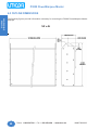
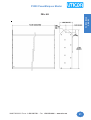
4.0 OUTLINE DIMENSIONS
The following figures provide information necessary for mounting the P3000 PowerMarquee Master
Displays.
1W x 4H
20
Phone: 1-563-359-7501 • Fax: 1-563-359-9094 • www.uticor.net
MAN-P3000-003
P3000 PowerMarquee Master
MAN-P3000-003 Phone: 1-563-359-7501 • Fax: 1-563-359-9094 • www.uticor.net
Outline
Introduction
Dimensions
2W x 4H
21
Outline
Dimensions
P3000 PowerMarquee Master
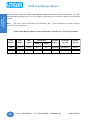
The table below shows the P3000 PowerMarquee Master dimensions and configurations. All Power
Marquee Master displays have a 4.18" unit depth. Unit weights are found in the general specifications
section.
Note:
The 8-inch narrow characters are denoted by “8N.” These characters are half the width of
the other 8-inch characters.
P3000 PowerMarquee Master unit Part Numbers, Dimensions, and Configurations.
Part
Number
Unit
Width
Unit
Height
1W4H
37.05"
2W4H
73.25"
22
Display Area
Character
Height (")
Characters
Per Line
Number
of Lines
9.6"
2/4/6/8/8N
20/10/6/5/10
4/2/1/1/1
9.6"
2/4/6/8/8N
40/20/13/10/20
4/2/1/1/1
Width
Height
12.08"
36"
12.08"
72"
Phone: 1-563-359-7501 • Fax: 1-563-359-9094 • www.uticor.net
MAN-P3000-003
Appendix A
In this chapter....
— PLC Wiring Diagrams
— Option Cards
A
P3000 PowerMarquee Master
Appendix A
PLC Cable Wiring Diagrams
The following diagrams depict the wiring pinouts for the PowerPanel Control Unit (located inside the
PowerMarquee) to PLC Cables. Use these diagrams to make a cable applicable to your type PLC and
application. Cable holes are provided in the Rear Access Panel, or you may need to drill your own.
PowerPanel Control Unit
Female
PLC
Port
(located on bottom of
unit)
8
1
9
15
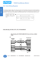
Allen-Bradley SLC500, 5/01, /02, /03 DH-485/AIC
Allen-Bradley SLC500 DH-485/AIC (Point-to-Point or Multidrop)
AB SLC500
DH-485
Panel PLC Port
RS-485
(13)Termination
TXD/RXD+ (1)
(9)
RD+
TXD/RXD- (2)
(10)
RD-
(11)
SD+
(12)
SD-
(6)
LE
LE
(5)
GND
(4)
GND
(7)
(5)
(1)
Phone type 8 pos.
A-2
D-sub 15-pin
Male
Phone: 1-563-359-7501 • Fax: 1-563-359-9094 • www.uticor.net
MAN-P3000-003
P3000 PowerMarquee Master
RS-232
AB SLC DF1
Appendix A
Introduction
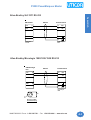
Allen-Bradley SLC DF1 RS-232
Panel PLC Port
TXD
(3)
(3)
RXD
RXD
(2)
(2)
TXD
GND
(5)
(5)
(1)
D-sub 9-pin
Female
D-sub 15-pin
Male
Allen-Bradley Micrologix 1000/1200/1500 RS-232
A-B Micrologix
PLC
RS-232
Panel PLC Port
TXD
(7)
(3)
RXD
RXD
(4)
(2)
TXD
GND
(2)
(5)
(1)
D-sub 15-pin
Male
.290"
.35"
Dia.
Mini Din 8-pin Male
Nonstandard keying
MAN-P3000-003 Phone: 1-563-359-7501 • Fax: 1-563-359-9094 • www.uticor.net
A-3
P3000 PowerMarquee Master
Appendix A
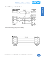
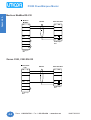
Allen-Bradley PLC5 DF1 RS-232
AB PLC5 DF1
RS-232
Panel PLC Port
(2)
(3)
RXD
RXD
(3)
(2)
TXD
GND
(7)
(5)
TXD
(1)
D-sub 25-pin
Male
D-sub 15-pin
Male
Control Techniques Unidrive 2-wire
A-4
Phone: 1-563-359-7501 • Fax: 1-563-359-9094 • www.uticor.net
MAN-P3000-003
P3000 PowerMarquee Master
Appendix A
Introduction
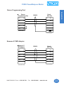
Control Techniques Unidrive 4-wire
Control Technology Corporation (CTC)
MAN-P3000-003 Phone: 1-563-359-7501 • Fax: 1-563-359-9094 • www.uticor.net
A-5
P3000 PowerMarquee Master
Appendix A
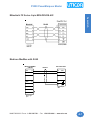
General Electric 90/30 and 90/70 15-pin D-SUB RS-422
Panel PLC Port
GE Fanuc
90/30
RS-422
(13)Termination
SD+
(13)
(9)
RD+
SD-
(12)
(10)
RD-
RD+
(11)
(11)
SD+
RD-
(10)
(12)
SD-
GND
(7)
(5)
(8)
(1)
D-sub 15-pin
Male
(15)
(5)
D-sub 15-pin
Male
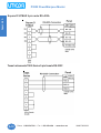
General Electric Versamax RS-232
Panel
PLC Port
RS-232
GE Versamax
RXD
(3)
(2)
TXD
TXD
(2)
(3)
RXD
GND
(5)
(5)
GND
9-Pin Dsub Male
15-Pin Dsub Male
Mitsubishi FX Series 25-pin RS-422
Mitsubishi
TXD
RS-232
Panel PLC Port
(3)
(3)
RXD
TXD
RXD
(2)
(2)
RTS
(5)
(7)
CTS
CTS
(4)
(8)
RTS
GND
(7)
(5)
(1)
D-sub 25-pin
Male
A-6
D-sub 15-pin
Male
Phone: 1-563-359-7501 • Fax: 1-563-359-9094 • www.uticor.net
MAN-P3000-003
P3000 PowerMarquee Master
Appendix A
Introduction
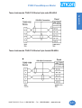
Mitsubishi FX Series 8-pin MINI-DIN RS-422
Modicon ModBus with RJ45
Modicon ModBus
w/RJ45
RS-232
Panel PLC Port
TXD
(3)
(3)
RXD
RXD
(4)
(2)
TXD
GND
(5)
(5)
(1)
D-sub 15-pin
Male
CTS
(7)
RTS
(6)
Phone Type
8-pin
MAN-P3000-003 Phone: 1-563-359-7501 • Fax: 1-563-359-9094 • www.uticor.net
A-7
P3000 PowerMarquee Master
Appendix A
Modicon ModBus RS-232
Modicon
ModBus
RS-232
Panel PLC Port
TXD
(3)
(3)
RXD
RXD
(2)
(2)
TXD
(5)
(5)
GND
(4)
(1)
(6)
D-sub 15-pin
Male
(7)
(8)
D-sub 9-pin
Male
Omron C200, C500 RS-232
Omron Host
Link
RS-232
Panel PLC Port
TXD
(2)
(3)
RXD
RXD
(3)
(2)
TXD
GND
(7)
CTS
(4)
RTS
(5)
(5)
(1)
D-sub 15-pin
Male
D-sub 25-pin
Male
A-8
Phone: 1-563-359-7501 • Fax: 1-563-359-9094 • www.uticor.net
MAN-P3000-003
P3000 PowerMarquee Master
Omron
Programming Port
RS-232
Appendix A
Introduction
Omron Programming Port
Panel
PLC Port
TXD
(2)
(3)
RXD
RXD
(3)
(2)
TXD
GND
(9)
(5)
GND
RTS
(4)
CTS
(5)
9-Pin Dsub Male
15-Pin Dsub Male
Siemens S7 MPI Adaptor
Siemens S7
MPI Adaptor
RS-232
Panel
PLC Port
RXD
(2)
(2)
TXD
TXD
(3)
(3)
RXD
GND
(5)
(5)
GND
RTS
(7)
(7)
CTS
CTS
(8)
(8)
RTS
9-Pin Dsub Female
15-Pin Dsub Male
MAN-P3000-003 Phone: 1-563-359-7501 • Fax: 1-563-359-9094 • www.uticor.net
A-9
P3000 PowerMarquee Master
Appendix A
Square D SYMAX 9-pin male RS-422A
Texas Instruments TI505 Series 9-pin female RS-232C
A-10
Phone: 1-563-359-7501 • Fax: 1-563-359-9094 • www.uticor.net
MAN-P3000-003
P3000 PowerMarquee Master
Appendix A
Introduction
Texas Instruments TI545-1102 Series 9-pin male RS-422A
Texas Instruments TI545-1104 Series 9-pin female RS-422A
MAN-P3000-003 Phone: 1-563-359-7501 • Fax: 1-563-359-9094 • www.uticor.net
A-11
P3000 PowerMarquee Master
Appendix A
Uni-Telway
A-12
Phone: 1-563-359-7501 • Fax: 1-563-359-9094 • www.uticor.net
MAN-P3000-003
P3000 PowerMarquee Master
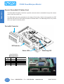
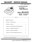
Option Card Installation Instructions
The option card has been installed into the backplane connector shown below of the PowerPanel
Control unit in the marquee. (The connector on the bottom right side of the card installs into the
backplane connector.) The card is secured with two screws.
Option Card is installed
into the Backplane
connector shown here
62-PIN SOCKET
MOUNT ON BACK SIDE OF
OPTION CARD
MAN-P3000-003 Phone: 1-563-359-7501 • Fax: 1-563-359-9094 • www.uticor.net
A-13
Appendix A
Introduction
If your PowerMarquee was shipped with an option card installed, (Allen-Bradley Data Highway
Plus, Generic DeviceNet I/O, Generic Ethernet I/O, Modicon Modbus Plus, Profibus-DP, or Serial
option card), you will need this information A connector, unique to each option, is attached to
these option boards and is accessible through the access plate in the back of the PowerMarquee
P3000 PowerMarquee Master
Appendix A
Generic DeviceNet I/O Option Card
The DeviceNet I/O Option Card has a special connector that is accessible through the access
panel in the rear of the unit.
The DeviceNet connector extends over the edge of the board. Next to the connector are DIP
Switches and then four LEDs that illuminate to indicate status. The Watchdog LED is only visible
when you open the access panelr.
DeviceNet Connector
DIP Switches
Status LEDs
Connector
Pin
Signal
Description
1
V-
Negative supply voltage
2
3
4
5
CAN_L
SHIELD
CAN_H
V+
CAN_L bus line
Cable shield
CAN_H bus line
Positive supply voltage
A-14
Watchdog LED
Phone: 1-563-359-7501 • Fax: 1-563-359-9094 • www.uticor.net
MAN-P3000-003
P3000 PowerMarquee Master
Generic Ethernet/ IP Option Card
The Ethernet /IP connector extends over the edge of the board. Next to the connector are DIP
Switches used for configuration, and four LEDs that illuminate to indicate status. The Watchdog
LED is only visible when you open the rear access panel. The module uses twisted-pair cables,
and no external termination is required.
RJ45 (Standard)
Pin
1
Signal
TD+
2
TD-
3
RD+
4
Termination
5
Termination
6
RD-
7
Termination
8
Termination
MAN-P3000-003 Phone: 1-563-359-7501 • Fax: 1-563-359-9094 • www.uticor.net
A-15
Appendix A
Introduction
The Ethernet/IP Option Card has a special connector that is accessible through the access panel
in the rear of the unit.
P3000 PowerMarquee Master
Appendix A
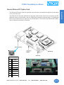
Modicon Modbus Plus Option Card
The Modbus Plus Option Card has a special connector that is accessible through the access
panel in the rear of the unit.
The Modbus connector (9-pin Female D-SUB) extends over the edge of the board. Two types of
connectors are available from Modicon for connecting devices to the network. Each inline drop
requires a line connector, Modicon part number AS-MBKT-085. This part number contains one
connector. The drops at the two ends of the cable, each require a terminating connector, Modicon
part number AS-MBKT-185. This contains two connectors.
The Modbus Plus node address can be set using the first six positions of the DIP switches
located at the top of the option board as shown in the diagram below. When the board is seated
in the panel, setting the DIP Switch in the UP position is the ON position. There are three Status
LEDs on the Modbus Plus option card: MBP, TXD, and RXD. The TXD and RXD LEDs indicate
the board is transmitting or receiving data. The MPB LED (leftmost LED) indicates Modbus Plus
status.
A-16
Phone: 1-563-359-7501 • Fax: 1-563-359-9094 • www.uticor.net
MAN-P3000-003
P3000 PowerMarquee Master
Generic Profibus-DP Option Card
The Profibus-DP connector extends over the edge of the board. Next to the connector are a
Termination Switch, Rotary Address Switches, and four LEDs that illuminate to indicate status.
FIELDBUS CONNECTOR
9-pin female D-SUB connector
D-SUB
Screw Terminal
Name
Housing
Shield
Connected to PE
1
Not connected
-
2
Not connected
-
3
B-Line
Positive RxD/TxD according
to RS-485 specification
4
RTS
Request to Send*
5
GND BUS
Isolated GND from RS-485
side*
6
+5 V BUS
Isolated +5 V from RS-485
side
7
Not connected
-
8
A-Line
Negative RxD/TxD according
to RS-485 specification
9
Not connected
-
* +5V BUS and GND BUS are used for bus termination. Some
devices, like optical transceivers (RS-485 to fiber optics) might
require external power supply from these points. RTS is used in some
equipment to determine the direction of transmission. In normal
applications only A-Line, B-Line, and Shield are used.
MAN-P3000-003 Phone: 1-563-359-7501 • Fax: 1-563-359-9094 • www.uticor.net
A-17
Appendix A
Introduction
The Profibus-DP Option Card has a special connector that is accessible through the access panel
in the rear of the unit.
P3000 PowerMarquee Master
Appendix A
Allen-Bradley Data Highway Plus Option Card
The Allen-Bradley Data Highway Plus/Remote I/O Option Card has a special connector attached
that is accessible through the access panel in the rear of the unit.
The option card has been installed to the backplane connector on the PowerPanel Control unit.
(The connector on the bottom right side of the card installs into the backplane connector.) The
card is secured with two screws.
The Allen-Bradley Data Highway Plus PLC connector extends over the edge of the board. Next to
the connector are two LEDs that illuminate to indicate status.
A-B DH+
Connector
Configuration
“ERROR” LED
Transmit
Enable LED
A-18
Phone: 1-563-359-7501 • Fax: 1-563-359-9094 • www.uticor.net
MAN-P3000-003
P3000 PowerMarquee Master
A-B DH+ Option Card Outline Drawing
Appendix A
Introduction
62-PIN SOCKET
MOUNT ON BACK SIDE
PowerPanel
Remote I/O
Option Card
A-B PLC Data
Highway Plus
Connector
1 Blue ______________________________ 1
Shield ______________________________ Shield
2 Clear _____________________________ 2
MAN-P3000-003 Phone: 1-563-359-7501 • Fax: 1-563-359-9094 • www.uticor.net
A-19
P3000 PowerMarquee Master
Appendix A
PowerMarquee Serial Option Board
If your PowerMarquee was shipped with a Serial Option Board installed, you will need this
information A connector is attached to this option board and is accessible through the access
panel in the rear of the unit.
The option card has been installed to the backplane connector on the the PowerPanel Conrol
unit. (The connector on the bottom right side of the card installs into the backplane connector.)
The card is secured with two screws.
The connector extends over the edge of the board. See the following pages for more information.
Serial Port COM3* (J1 15-Pin Female Connector)
*This port can use RS-485
Pin
1
2
3
4
5
6
7
8
9
10
11
12
13
14
15
A-20
Signal
Chassis GND
TXD
RXD
+5V
Signal GND
LE
CTS
RTS
RXD+
RXDSD+
SDTERM
N.C.
N.C.
Description
Chassis Ground
RS-232 Serial Data Output
RS-232 Serial Data Input
+5V Through 120 Ohm Resistor
Signal Ground
RS-232 Clear To Send
RS-232 Request To Send
RS-422/485 Serial Data Input +
RS-422/485 Serial Data Input RS-422/485 Serial Data Output +
RS-422/485 Serial Data Output RS-422/485 120 Ohm Termination Resistor Connect to Pin 9
Phone: 1-563-359-7501 • Fax: 1-563-359-9094 • www.uticor.net
MAN-P3000-003
P3000 PowerMarquee Master
Appendix A
Introduction
Serial Port COM2* (J2 9-Pin Female Connector)
*This port CANNOT use RS-485
Pin
1
2
3
4
5
6
7
8
9
Signal
SDTXD
RXD
RXDSignal GND
SD+
CTS
RTS
RD+
Description
RS-422 Serial Data Output RS-232 Serial Data Output
RS-232 Serial Data Input
RS-422 Serial Data Input Signal Ground
RS-422 Serial Data Output +
RS-232 Clear To Send
RS-232 Request To Send
RS-422 Serial Data Input +
MAN-P3000-003 Phone: 1-563-359-7501 • Fax: 1-563-359-9094 • www.uticor.net
A-21
Appendix A
P3000 PowerMarquee Master
This page intentionally left blank.
A-22
Phone: 1-563-359-7501 • Fax: 1-563-359-9094 • www.uticor.net
MAN-P3000-003