1
User Manual
Power Wave 3
Emergency Lighting Inverter
10 KVA - 50 KW
Document No. 6002-1443
Revision M
Installation and
Operation
Due to continuous product improvements, this document is subject to change without notice.
OnLine Power
TABLE OF CONTENTS
SECTION
PAGE
PROPRIETARY NOTICE
C
SECTION 1 - SAFETY
1-1
SECTION 2 - OVERVIEW
2-1
2.1
2.2
2.3
2.4
2.5
2.6
INTRODUCTION
Illustration 2.1: Power Wave 3
BENEFITS
PRODUCT FEATURES
Illustration 2.2: Component Layout
Illustration 2.3: Sub Assembly Component Location
FUNCTIONAL DESCRIPTIONS
Illustration 2.4: Functional Block Diagram for Single Input Power System
Illustration 2.5: Functional Block Diagram for Dual Delta Input Power System
Illustration 2.6: Functional Block Diagram for Dual Wye Input Power System
THEORY OF OPERATION
OUTPUT LOADS
SECTION 3 - OPERATION
3.1
3.2
3.3
3.4
3-1
START-UP PROCEDURES
OPERATION
FIELD REPLACEABLE UNITS
Illustration 3-1: 40KVA and lower Heat Sink Assembly (FRU)
Illustration 3-2: 50 KVA and up Heat Sink Assembly (FRU)
REPLACEABLE PARTS LIST
SECTION 4 – SYSTEM OPTIONS
3-1
3-3
3-3
3-4
3-5
3-6
4-1
4.1
MAINTENANCE BYPASS SWITCH
Illustration 4-1: External Maintenance Bypass Switch Diagram
Illustration 4-2: Maintenance Bypass Switch
4.1.3 External Manual Bypass Switch
4.2
AUDIO ALARM WITH SILENCE SWITCH
4.3
REMOTE UPS STATUS PANEL
Illustration 4-2-1: Remote Status Panel
4.4
FORM “C” CONTACTS FOR ALARMS
4.5
Optional TVSS
4.6
NORMALLY ON NORMALLY OFF OUTPUT AUX. CIRCUIT BREAKERS
4.7
EXTERNAL OUTPUT AUX.CIRCUIT BREAKERS
Illustration 4-3: UPS with External Load Center
4.8
10% INPUT CURRENT HARMONIC FILTER
4.9
5% INPUT CURRENT HARMONICS FILTER
4.10 EMI FILTER
4.11 OPTIONAL HIGHER KAIC NORM ON/OFF OUTPUT CIRCUIT BREAKERS
4.12 DUAL INPUT SYSTEM WYE/WYE
4.13 DUAL INPUT SYSTEM DELTA/WYE
6002-1443 Rev M
2-1
2-1
2-2
2-3
2-4
2-5
2-6
2-8
2-9
2-10
2-11
2-12
a
4-2
4-2
4-4
4-5
4-6
4-6
4-6
4-7
4-7
4-7
4-8
4-8
4-9
4-9
4-9
4-9
4-10
4-10
OnLine Power
SECTION
PAGE
4.14
4.15
4.16
4.17
4.17.1
DUAL INPUT SYSTEM DELTA/DELTA
SEISMIC MOUNTING BRACKET
STACKABLE RACK
Global Monitoring System (GMS)
Local on PC via RS 232
Illustration 4-8: Sample PC Screen
4.17.2 Local on PC via RS 485
4.17.3 Remote Dial Up: Data, Voice, Fax, Pager, PC, E-mail, Event Log, and Stats
Illustration 4-9: Monitoring 2000 Front View
Illustration 4-10: Manager 2000 Screen
4.18. ECC – EMERGENCY CIRCUIT CONVERTER
4.19 ECM – EMERGENCY CONTROL MODULE
SECTION 5 - MAINTENANCE
5.1
5.2
5.3
5.4
5.5
4-10
4-10
4-10
4-11
4-11
4-11
4-11
4-12
4-12
4-12
4-19
4-20
5-1
SAFETY PRECAUTIONS
WHEN TO CALL
STEPS TO TAKE
PREVENTIVE MAINTENANCE
ONLINE POWER CUSTOMER SERVICE AND SUPPORT
5-1
5-3
5-3
5-4
5-8
APPENDICES
APPENDIX A – SPECIFICATIONS
APPENDIX B – BATTERY CONNECTIONS
APPENDIX C – LCD DISPLAY MENU AND TROUBLE SHOOTING GUIDE
APPENDIX D – DRAWINGS & TABLES.
SECTION 6 - INSTALLATION
6.1
6.2
6.3
6.4
6.5
6002-1443 Rev M
A-1
B-1
C-1
D-1
6-1
SITE PLANNING AND PREPARATION
Table 6-A: Site Planning Specifications
Illustration 6-1: Cable Access and Mounting
Illustration 6-2:UPS Cabinet Center of Gravity
Illustration 6-3: Battery Cabinet Center of Gravity
EQUIPMENT UNPACKING
Illustration 6-4: Fork lifting
UNIT INSTALLATION
Illustration 6-5: Power Wave Customer’s Connection
REMOTE SIGNALLING CONNECTIONS FORM "C" DRY CONTACT (OPTIONAL)
BATTERY STORAGE
b
6-1
6-1
6-2
6-3
6-4
6-5
6-5
6-6
6-7
6-8
6-9
OnLine Power
OnLine Power, Inc.
Reproduction or Distribution forbidden
NOTICE: THIS DOCUMENT CONTAINS PROPRIETARY INFORMATION
This document contains proprietary and confidential information of
OnLine Power, Inc. (”OnLine Power”). In consideration of the receipt of
this document, the recipient agrees not to copy any of its contents, nor to
disclose them to or allow them to be used by any person not currently an
OnLine Power employee or an employee of the recipient having a need to
know, without the express written consent of OnLine Power, and further
agrees to surrender this document to OnLine Power when the reason for
its receipt has terminated. Due to continuous product improvement, this
document is subject to change without prior notice.
© 2009 OnLine Power, Inc. – All rights reserved
6002-1443 Rev M
c
OnLine Power
Congratulations on selecting one of the fine products from OnLine Power, the leader in power
protection technology. Our wide product offering includes UPS (Uninterruptible Power Systems), power
conditioners, automatic voltage regulators and specialty transformers (e.g., computer-grade, medicalgrade). Since our founding in 1972, OnLine Power has shipped many of these fine products to
discerning customers around the world for use on sensitive equipment and in critical applications.
One of our goals is to make our manuals both comprehensive and easy to use. The new format of our
user manual is the result of ideas and inputs from customers like you who have taken an active interest
in our continued success. We invite and appreciate your feedback on our products and documentation
via e-mail, fax, mail, or telephone.
SALES
Phone: (800) 227-8899
FAX No: (323) 721-3929
E-mail: [email protected]
Office Hours are 7:00 AM to 5:00 PM PST
WARRANTY REGISTRATION AND WARRANTY CERTIFICATE REQUEST
www.800pwrsrvc.com
SERVICE
If you require assistance, please call our 24-hour toll free hot line 800-PWR-SRVC (800-797-7782) or
email to [email protected]. Please have the following information from your unit’s nameplate
available to speed assistance:
Serial Number:
KVA/Power Rating:
Input Voltage:
Output Voltage:
Manufacturer Date:
Due to continuous product improvement this document is subject to change without prior notice.
6002-1443 Rev M
d
OnLine Power
SECTION 1 - SAFETY
Following safety precautions are important when operating or servicing electrical
equipment. The symbols shown are used extensively throughout this manual.
Always heed these precautions since they are essential to the safe operation and
servicing of this product.
Boxes labeled with the “
Danger!” symbol indicate that there is a high risk of
personal injury or death if instructions are not followed.
Warnings labeled with the Caution symbol indicate that there is a high
probability of equipment malfunction, damage, or destruction if instructions are not
followed.
Danger!
ONLY FACTORY TRAINED OR AUTHORIZED PERSONNEL SHOULD ATTEMPT
TO INSTALL OR REPAIR THE UNIT OR ITS BATTERY SYSTEM. IMPROPER
INSTALLATION HAS PROVEN TO BE THE SINGLE MOST SIGNIFICANT
CAUSE OF START-UP PROBLEMS.
HIGH AC AND DC ELECTRICAL
VOLTAGES ARE PRESENT THROUGHOUT THE UNIT (S) AND INCORRECT
INSTALLATION OR SERVICING COULD RESULT IN ELECTROCUTION, FIRE,
EXPLOSION, OR EQUIPMENT MALFUNCTION.
Danger!
READ THIS MANUAL IN ITS ENTIRETY BEFORE PERFORMING
INSTALLATION, START-UP, OPERATION, AND MAINTENANCE OF THE UNIT
OR BATTERY SYSTEMS. FAILURE TO DO SO COULD RESULT IN
ELECTROCUTION, FIRE, EXPLOSION, OR EQUIPMENT MALFUNCTION.
If you require assistance, calls toll free 800-PWR-SRVC (800-797-7782). Please have the
following information from your unit’s nameplate available to speed assistance:
Serial Number:
KVA/Power Rating:
Input Voltage:
Output Voltage:
Manufacturer Date:
6002-1443 Rev M
1-1
OnLine Power
Danger!
ALL POWER CONNECTIONS MUST BE COMPLETED BY A LICENSED
ELECTRICIAN WHO IS EXPERIENCED IN WIRING THIS TYPE OF EQUIPMENT.
WIRING MUST BE INSTALLED IN ACCORDANCE WITH ALL APPLICABLE
NATIONAL AND LOCAL ELECTRICAL CODES. IMPROPER WIRING MAY
CAUSE DAMAGE TO THE EQUIPMENT, INJURY OR DEATH OF PERSONNEL.
VERIFY THAT ALL HIGH AND LOW VOLTAGE INPUT POWER CIRCUITS ARE
DE-ENERGIZED AND LOCKED OUT BEFORE INSTALLING CABLES OR
MAKING ANY ELECTRICAL CONNECTIONS.
Danger!
EXERCISE EXTREME CARE WHEN HANDLING UNIT AND BATTERY
CABINETS TO AVOID EQUIPMENT DAMAGE OR INJURY TO PERSONNEL.
CABINETS WEIGH SEVERAL HUNDRED POUNDS.
Danger!
TEST LIFT AND BALANCE THE CABINETS BEFORE MOVING. MAINTAIN
MINIMUM TILT FROM VERTICAL AT ALL TIMES. THE BOTTOM STRUCTURE
WILL SUPPORT THE UNIT ONLY IF THE FORKLIFT FORKS ARE
COMPLETELY UNDERNEATH THE UNIT.
Danger!
OBSERVE ALL BATTERY SAFETY PRECAUTIONS DURING INSTALLATION
OR SERVICE OF THE UNIT OR BATTERIES. EVEN WITH THE BATTERY
CIRCUIT BREAKER IN THE OFF POSITION, THE DANGER OF
ELECTROCUTION MAY STILL BE PRESENT. THE BATTERY POWER TO THE
UNIT MUST BE LOCKED AND TAGGED “OFF” BEFORE PERFORMING ANY
SERVICE OR WORK ON THE UNIT. THE BATTERY MANUFACTURER’S
SAFETY INFORMATION AND MATERIAL SAFETY DATA SHEET IS LOCATED
IN A POCKET ATTACHED TO THE INSIDE OF LEFT DOOR OF EACH UNIT.
FAILURE TO FOLLOW INSTRUCTION LISTED ABOVE AND ELSEWHERE IN
THIS MANUAL COULD RESULT IN AN EXPLOSION, FIRE, EQUIPMENT
MALFUNCTION, OR ELECTROCUTION.
6002-1443 Rev M
1-2
OnLine Power
Danger!
ALL POWER TO THE UNIT MUST BE LOCKED AND TAGGED “OFF” BEFORE
PERFORMING ANY SERVICE OR WORK ON THE UNIT. FAILURE TO DO SO
COULD RESULT IN ELECTROCUTION.
Danger!
IN A FIRE INVOLVING ELECTRICAL EQUIPMENT, ONLY USE CARBON
DIOXIDE FIRE EXTINGUISHERS, OR THOSE APPROVED FOR USE ON
ELECTRICAL EQUIPMENT. USE OF WATER ON FIRES INVOLVING HIGH
VOLTAGE ELECTRICAL CIRCUITS COULD RESULT IN ELECTROCUTION .
Danger!
EXTREME CAUTION IS REQUIRED WHEN PERFORMING MAINTENANCE.
LETHAL VOLTAGES EXIST WITHIN THE EQUIPMENT DURING OPERATION.
OBSERVE ALL WARNINGS AND CAUTIONS IN THIS MANUAL. FAILURE TO
COMPLY MAY RESULT IN SERIOUS INJURY OR DEATH. OBTAIN QUALIFIED
SERVICE FOR THIS EQUIPMENT AS INSTRUCTED.
Danger!
BE CONSTANTLY AWARE THAT THE UNIT SYSTEM CONTAINS HIGH DC AS
WELL AS AC VOLTAGES. WITH INPUT POWER OFF AND THE BATTERY,
DISCONNECTED, HIGH VOLTAGE AT THE FILTER CAPACITORS AND POWER
CIRCUITS SHOULD DISCHARGE WITHIN 30 SECONDS. HOWEVER, POWER
CIRCUIT MALFUNCTIONS CAN OCCUR, SO YOU SHOULD ALWAYS ASSUME
THAT HIGH VOLTAGE MIGHT STILL EXIST AFTER SHUTDOWN. VERIFY
THAT POWER IS OFF USING AC AND DC VOLTMETERS BEFORE MAKING
CONTACT.
Danger!
SOME COMPONENTS WITHIN THE CABINETS ARE NOT CONNECTED TO
CHASSIS GROUND. ANY CONTACT BETWEEN FLOATING CIRCUITS AND
THE CHASSIS IS A LETHAL SHOCK HAZARD.
6002-1443 Rev M
1-3
OnLine Power
Danger!
INTERNAL BATTERY STRAPPING MUST BE VERIFIED BY THE CUSTOMER
PRIOR TO MOVING THIS UNIT.
THIS UNIT CONTAINS NON-SPILLABLE BATTERIES.
KEEP THE UNIT
UPRIGHT. DO NOT STACK. DO NOT TIP. ALWAYS FOLLOW THE BATTERY
MANUFACTURER’S SAFETY INFORMATION LOCATED IN A POCKET
ATTACHED TO THE INSIDE OF THE LEFT DOOR OF YOUR UNIT TO PREVENT
AN ACCIDENT THAT COULD RESULT IN INJURY OR DEATH.
Danger!
LEAD-ACID BATTERIES CONTAIN HAZARDOUS MATERIALS. BATTERIES
MUST BE HANDLED, TRANSPORTED, AND RECYCLED OR DISCARDED IN
ACCORDANCE WITH FEDERAL, STATE, AND LOCAL REGULATIONS.
BECAUSE LEAD IS A TOXIC SUBSTANCE, LEAD-ACID BATTERIES MUST BE
RECYCLED OR DISCARDED AS HAZADEROUS WAIST.
DO NOT DISPOSE OF BATTERIES IN A FIRE, THE BATTERIES MAY
EXPLODE.
DO NOT OPEN OR MUTILATE THE BATTERIES. RELEASED ELECTROLYTE
IS HARMFUL TO THE SKIN AND EYES AND MAY BE TOXIC.
A BATTERY CAN HAVE A HIGH SHORT CIRCUIT CURRENT AND PRESENT A
RISK OF ELECTRICAL SHOCK. THE FOLLOWING PRECAUTIONS SHOULD
BE OBSERVED WHEN WORKING ON BATTERIES:
1.
2.
3.
4.
5.
6
7
8
6002-1443 Rev M
REMOVE WATCHES, RINGS OR OTHER METAL OBJECTS.
USE TOOLS WITH INSULATED HANDLES.
WEAR RUBBER GLOVES AND BOOTS.
DO NOT LAY TOOLS OR METAL PARTS ON TOP OF BATTERIES.
DISCONNECT CHARGING SOURCE PRIOR TO CONNECTING OR
DISCONNECTING BATTERY TERMINALS.
DETERMINE IF BATTERY IS INADVERTENTLY GROUNDED.
IF SO,
REMOVE THE SOURCE OF THE GROUND. CONTACT WITH ANY PART OF
A GROUNDED BATTERY CAN RESULT IN ELECTRICAL SHOCK. THE
LIKELIHOOD OF SUCH SHOCK WILL BE REDUCED IF SUCH GROUNDS
ARE REMOVED DURING INSTALLATION AND MAINTENANCE.
LEAD-ACID BATTERIES CAN PRESENT A RISK OF FIRE BECAUSE THEY
GENERATE HYDROGEN GAS. THE FOLLOWING PROCEDURES SHOULD
BE FOLLOWED:
1. DO NOT SMOKE WHEN NEAR BATTERIES.
2. DO NOT CAUSE FLAME OR SPARK IN BATTERY AREA.
DISCHARGE STATIC ELECTRICITY FROM YOUR BODY BEFORE
TOUCHING BATTERIES BY FIRST TOUCHING A GROUNDED SURFACE.
1-4
OnLine Power
SECTION 2 – OVERVIEW
2.1
INTRODUCTION
Power Wave 3 Central Lighting Inverters are manufactured to provide critical power for lighting during a
power outage. The Power Wave 3 meets or exceeds life safety codes of UL924, UL924A (as an option for
shorter than 90 minutes use in conjunction with a generator), UL1778 and NFPA101. These codes were
established to allow emergency lighting inverters to provide critical power to lighting circuits during a power
malfunction. The emergency lighting inverter will provide power for 90 minutes to allow safe and orderly
evacuation from the facility.
When input power to the Power Wave 3 is lost during a power outage, the system will automatically draw
power from its battery bank supply without any interruption and with zero transfer time. The critical load will
receive only clean sine wave power. The output transformer provides multiple output voltages as well as
input voltages that are different than the output voltages. The standard VRLA (Valve Regulated Lead-acid),
maintenance-free batteries provide 90 minutes of backup power as standard.
Upon restoration of input power, the Power Wave 3 automatically resumes normal operation, and
immediately begins to recharge the batteries for the next power outage.
The Power Wave 3 has an internal bypass circuit, which maintains the power to the load in case of internal
system or component malfunction.
The Power Wave 3 provides comprehensive monitoring capabilities. In addition to the LCD display, it
provides four dry relay contacts for remote monitoring capabilities. The Power Wave 3 contains, as
standard features, AS 400, RS 232, RS485 data transmission ports with optional soft-ware and many other
communication options.
The Power Wave 3 is an on-line three phase PWM high frequency, digital signal processing, true double
conversion inverter system available in output ratings of 10, 15, 20, 25, 30, 40, 50 KVA and 50 KW. The
Power Wave 3 is listed for compliance to UL1778, UL924, UL924A and CSA107.1 standards. The Power
Wave 3 is available with an input or output voltages of 480Y/277 or 208Y/120 VAC, three phase. This
information is provided on the nameplate located on the inside front door of the unit. See Appendix A for a
complete listing of the Power Wave 3 specifications.
The Output transformer performs two critical functions. First, it provides excellent common mode and
normal mode noise isolation of the load from the input or inverter power. Secondly, it provides voltage
transformation and tight regulation of the output voltage while the Power Wave is operating from its internal
inverter and it can be utilize to provide a different voltage than input (source voltage).
ILLUSTRATION 2-1 POWER WAVE 3
6002-1443 Rev M
2-1
OnLine Power
2.2
BENEFITS
Power Wave 3 is a self-contained simple solution for back-up power for any fluorescent or incandescent
lighting source such as overhead fixtures, exit signs, etc. It has been specifically designed to maintain 90
minutes of lighting power and ensure a safe building evacuation.
In addition, since electrical disturbances can come from practically anywhere, e.g., from the incoming power
lines, from within a building, outside electrical disturbances include lightning strikes, utility switching, brownouts, and accidents. Electrical disturbances in a facility can be caused by load cycling (elevators, HVAC
systems, etc.), fault conditions, welders, and other electrical noisy equipment. Whether the electrically
disturbances are generated outside or within the facility, the following power problems can occur:
•
Complete power outages.
•
Brown-outs including momentary sags.
•
Voltage surges.
•
Transients including common-mode and transverse-mode noise.
•
Frequency shifts and fluctuations.
The Power Wave 3 offers significant advantages over other alternatives. For example, just one of the
smallest Power Wave 3 Central Lighting Inverters can replace over 70 ”bug eyes” to make service and
maintenance in a centralize place much quicker and easier.
The air cooled, OnLine PWM (zero transfer) inverter system, is virtually silent and can be installed
anywhere.
On-line PWM technology provides switchover from utility to battery power without any interruption.
The Power Wave 3 is designed to fit the needs of virtually all power conditioning and emergency lighting
backup applications. It has been designed to power all forms of lighting fixture including HID, incandescent,
fluorescent light, communication, and process control equipment. The Power Wave 3 does not require any
de-rating, as other products may, when powering 100% lighting fixture including switching mode power
supplies and or HID, incandescent, fluorescent lights.
6002-1443 Rev M
2-2
OnLine Power
2.3
PRODUCT FEATURES
The Power Wave 3 is designed in module concept for ease of maintenance and repair, all electronic are
centralize in two-assembly module. The following describes the major blocks within the Power Wave 3.
Please refer to Illustration 2-2 Subassembly Component Location to find specific items.
2.3.1
Input Contactor K1 (Illustration 2-3, Item 20)
The input contactor is multifunctional. First, it provides connections for the input power to the unit.
Secondly, the contactor disconnects the input line when an outage occurs so that there is no back feeding of
power into the power line. Finally, the contactor allows for automatic unit operation upon a complete
discharge of the batteries. No operator intervention is required when power to the unit is restored after a
complete battery discharge.
2.3.2
Input Transformer (T3) (Illustration 2-2, Item 2)
The input transformer adjusts the input voltage for proper rectifier DC voltage, depending on the unit rated
power and back-up capacity.
2.3.3
Battery Charger (Illustration 2.3, Electronics Tray)
The constant power battery charger maintains the batteries at full charge while utility power is available.
After a battery discharge, the charger will automatically recharge the batteries upon restoration of input
power. This circuit is on the Power Board.
2.3.4
Power Board Assembly with IGBT’s (Illustration 2.3, Item 3)
The Power Board is bolted onto the IGBT (Insulated Gate Bipolar Transistor) blocks that are mounted on a
heat sink. The complete Heat Sink Assembly with IGBTs and Power Board is replaceable as a single part.
This FRU (Field Replaceable Assembly) converts all the power, i.e. input AC power converted to DC bus,
battery power boosted to DC bus, and finally DC bus power converted to output AC power using PWM with
digital signal processing technology for a smooth AC sine wave. In case of a malfunction, the complete Heat
Sink Assembly is easily replaceable using only a screwdriver. The Power Board also contains the
housekeeping power supplies and drivers for the IGBTs. The entire assembly provides the landing place for
all internal input, output, DC cables and metering devices for control and monitoring of the unit input and
output parameters.
2.3.5
Control Board (Illustration 2.2, Item 10)
The on board microprocessor with unit specific firmware and control circuitry is located on the Control Board.
The Control Board is mounted on the cabinet door and communicates with the Power Board (A2) via a
ribbon cable. It monitors the input and output voltages and generates the command to close or open the
input contactor and to sense and change the status of the bypass static switch. The Control Board sends
data to the LCD panel located on the door where actual status and parameters are displayed. It additionally
has AS400, RS232 and RS485 output capabilities and supports various communication options.
2.3.6
Static Bypass Switch (Illustration 2.2, Item 18)
The Static Bypass Switch is a fully rated solid-state device capable of switching the critical load between the
inverter output and the normal AC by pass line. In the event of a system output overload of 125% or more of
the unit full-load current rating, a make-before-break (both directions) transfers power to the bypass source
via a static switch.
2.3.7
LCD Display Panel (Illustration 2.2, Item 11)
The unit display, via a 4 by 20 backlit character display, provides all the input, output, battery metering, alarm
data, and unit status for customer use on a constantly scrolling set of two monitor measurement default
screens with continuous update at a very high frequency.
6002-1443 Rev M
2-3
OnLine Power
2.3.8
Output Isolation Transformer (Illustration 2.2, Item 1)
The output isolation transformer provides isolation between the inverter and critical load. The power to the
primary of this transformer is received form the unit and is transformed to required output voltage levels.
2.3.9 Maintenance Bypass Switch (Illustration 2.2, Item 28)
The MBS (Maintenance Bypass Switch) removes the critical load from the backup power and providing utility
input directly to the load in case of a malfunction of the unit or during system maintenance.
2.3.10 Battery Bank – located in External Battery Cabinet(s)
The battery bank consists of sealed, maintenance-free valve regulated (VRLA Type) batteries as standard.
The batteries provide emergency power during power outages. The battery bank includes a breaker for over
current protection and DC disconnect for each cabinet or string to allow the servicing of the battery.
2.3.11
System Component Layout
ILLUSTRATION 2-2: COMPONENT LAYOUT
6002-1443 Rev M
2-4
OnLine Power
1.
2.
3.
4.
5.
6.
Output Transformer (T1)
Input Transformer (T3)
Power Board Assembly (A1)
Interconnect Terminal Block
(Input T4B, Output TB1, Battery
TB3, DC B5)
Output Inductor (L2)
Diode Bridge (Pre-charge)
7.
DC Choke (L4)
9.
High Frequency Noise Filter
Capacitors, Output and Battery
Power
Control Board (A2)
LCD Display Board
Output High Frequency Filter
(C5, C6, C7)
Terminal Block to remove heat
sink assembly (TB4)
Control Power (40 kva and lower)
Transformer (T2A)
Fan Fuse (F3 - F6)
IGBT Heat Sink Assembly
Control Fuses (F2, F1)
Heat Sink (Bypass SCR)
Fan(s) (B1 - B6)
Input Contactor (K1)
Ground Terminal (Option w/ item 25)
Input Breaker (CB1)
Battery Breaker (CB2)
Output Breaker (CB3)
Output Distribution Breakers
(Optional)
Neutral Bus (Option w/ item 25)
Customer Input/Output
Connection Terminal Blocks
Maintenance Bypass Switch
(SW1)
SCRs and Snubbers
Contactor Coil Transformer (T5)
Fan Transformer (T4)
Inverter Test Switch
RS232 /RS485 (Option)
TVSS (Option)
Ground Lug
5 Form “C” Alarm Terminal
(Option)
MBS S –1 Toggle Switch or
maintenance bypass switch with 3
positions.
10.
11.
12.
13.
14.
15.
16.
17.
18.
19.
20.
21.
22.
23.
24.
25.
26.
27.
28.
29.
30.
31.
32.
33.
34.
35.
36.
37.
ILLUSTRATION 2-3: SUB-ASSEMBLY COMPONENT LOCATION
6002-1443 Rev M
2-5
OnLine Power
2.4
FUNCTIONAL DESCRIPTION
Illustrations 2-2 thru 2-6 depict functional block diagrams of the Power Wave 3. These diagrams provide an
excellent tool for identifying the major building blocks within the Power Wave.
2.4.1
Main input circuit breaker - optional
The main input circuit breaker provides Power Wave 3 with incoming power isolation as a well as means of
disconnect and input over current protection.
2.4.2
Input Contactor
The Input contactor controls power applied to the unit. The microprocessor control circuit verifies that the unit
is in “normal” condition and that the input voltage and frequency are within an acceptable range. When the
unit transfers to the battery, it disconnects the source so the batteries do not feed back to the utility.
2.4.3
Input Inductors
The input inductors are a three-phase input filter.
2.4.4
Inverter
The inverter provides continuous power to the load. When the AC input power is not available, the inverter
converts the energy stored in the battery bank to AC power to supply the load. The PWM (Pulse Width
Modulation) inverter utilizes high frequency, digital signal processing with high efficiency IGBTs for fast
accurate measurement and response.
2.4.5
Battery charger
The constant power battery chargers supply DC power to re-charge and to maintain the charge on the
battery bank. The charger is fully automatic with a current tapering feature so that battery damage will be
prevented in case of a charger malfunction or increased battery temperature. The charger is sized to
maintain a full charge even when the input voltage at is the low line limit for indefinite periods of time meets
and exceeds the UL 924 requirement.
2.4.6
Battery
The battery bank; consist of 16, 24, 26 or 46, 12-volt batteries (depending on the unit's specified capacity),
providing the reserve energy to sustain the load when suitable AC input power is not present. The batteries
are designed and tested to meet UL 924 requirements. The standard VRLA (Valve Regulated Lead Acid)
batteries are sealed and maintenance-free.
2.4.7
DC Choke
The DC choke helps boost battery voltage to a higher internal DC bus voltage while it reduces high
frequency noise.
2.4.8
Output AC Inductor
The Output AC Inductor acts as a filter circuit component to reduce high frequency noise to the output
transformer.
2.4.9
Output Transformer
The Output transformer performs two critical functions. First, it provides excellent common mode and normal
mode noise isolation of the load from the input or inverter power. Secondly, it provides voltage
transformation and tight regulation of the output voltage while the Power Wave is operating from its internal
inverter and it can be utilize to provide a different voltage than input (source voltage).
6002-1443 Rev M
2-6
OnLine Power
2.4.10 Inverter Test Switch
The Inverter Test Switch is a momentary push button for manually testing the Power Wave 3 and its
batteries for proper operation. With Power Wave 3 in operation, the test switch is pushed and held; the unit
will automatically transfer to battery operation manually. The unit will continue to run on batteries until the
switch is released. Upon release, the Power Wave 3 transfers back to utility from the battery and resumes
normal operation.
2.4.11 Input Transformer
The Input Transformer conditions the voltage ahead of the DC rectifier, and supplies power to the inverter
and battery charger.
2.4.12 Maintenance Bypass Switch (MBS)
This Maintenance Bypass Switch (MBS) allows the Power Wave 3 to be switched off line for maintenance or
troubleshooting when the inverter malfunctions or PM (Periodic Maintenance) is required. The MBS transfers
the input power directly to critical load without any break or power disruption. Before switching the MBS to
the maintenance position, turn on toggle switch S1 if unit is so equipped, and then rotate the maintenance
bypass switch to the maintenance (MAN) position. Refer to the operation label on the unit. After repair or
periodic maintenance, the MBS must be switched to UPS position, in cases where the toggle switch has
been incorporated with the switch, be sure not to leave the switch in the middle position as this will not
provide any output power when the unit is off.
Caution!
STOPPING ROTATION OF THE MAINTENANCE BYPASS SWITCH BETWEEN
POSITIONS WILL RESULT IN THE REMOVAL OF OUTPUT VOLTAGE.
6002-1443 Rev M
2-7
OnLine Power
.
ILLUSTRATION 2-4: FUNCTIONAL BLOCK DIAGRAM FOR SINGLE INPUT POWER
6002-1443 Rev M
2-8
OnLine Power
ILLUSTRATION 2-5: FUNCTIONAL BLOCK DIAGRAM FOR DUAL DELTA INPUT POWER
6002-1443 Rev M
2-9
OnLine Power
1
*Internal or External Cabinet
ILLUSTRATION 2-6: FUNCTIONAL BLOCK DIAGRAM FOR DUAL WYE INPUT POWER
6002-1443 Rev M
2-10
OnLine Power
2.5
THEORY OF OPERATION
The Power Wave 3 utilizes on-board microprocessor that continuously monitor, control and display all
functions (measurement, alarm, alert, and system status) in real time by utilizing high frequency digital
signal processing; a reliable and user friendly battery back up system.
2.5.1
Standby Mode
After power is applied, the system is placed in the STANDBY mode and a self-check starts. During this
period, the start-up subroutine program checks for input voltage and proper operation of the inverter and
bypass SCR’s. After the sub-routine is completed and the system is confirmed OK, the system goes into the
NORMAL mode.
2.5.2
Normal Mode
The input contactor K1 receives a closing signal, connecting input power to the input transformer. The
rectifier supplies DC power to the battery charger, Control Board and the DC/AC inverter circuit. The battery
charger is then activated allowing the batteries to be continuously charged. The on-line DC/AC inverter
converts the DC voltage to a (PWM) Pulse-Width-Modulation waveform. This waveform is filtered and
reconstructed to a desired AC output by using high frequency digital signal processing.
2.5.3
Response To Input Power Abnormal Condition
If the system controller senses an input frequency change of more than +3 Hz or an out of range input
voltage, it will consider it an input malfunction and immediately open the input contactor, isolating the unit
from the facility power. At the same time, the charger is turned off and the battery bank becomes a DC
supply source to the inverter circuit, maintaining an uninterrupted AC supply to the protected load. The LCD
screen will display a ”UNIT PROBLEM /ALARM” message. When the facility power returns, stabilizes and is
in phase with the backup power, the system controller closes the input contactor and the system returns to
normal. If the battery voltage drops below useable voltage and the facility power remains off, the system will
assume a standby mode, and will only resume normal operation upon restoration utility power.
2.5.4
UNIT MESSAGES
The System controller will issue a "Failure/ Alert" message on the LCD screen if any of the following
conditions happen during the power outage:
•
Internal malfunction
•
System overheats.
•
DC bus Overvoltage/Undervoltage
During a malfunction the system stops its backup operation, inverter SCRs are switched OFF and bypass
SCRs are switched ON without any interruption to the load. A summary alarm 5-volt signal is sent to the
hardwired interface. The system remains in this mode until power is cycled or the system has been repaired
if needed.
6002-1443 Rev M
2-11
OnLine Power
2.5.5
Unit "Problem/Alarm" Message
The System controller will issue a unit problem/alarm message on the LCD screen if any of the following
conditions occur:
•
Input power abnormality
•
Battery bank under voltage
•
Charger OFF
•
Output overload
During a Problem/Alarm mode, inverter IGBTs remain on and an alarm signal may be sent to the signal
interface. The system will reset itself as soon as the problem/alarm has been cleared.
2.6
OUTPUT LOADS
The Power Wave 3 is designed to power any fluorescent or incandescent, HID lighting. There are, however,
certain types of loads that exhibit an excessive inrush current when first turned on or at other times during
operation. Please check load requirements for proper sizing of the system.
6002-1443 Rev M
2-12
OnLine Power
SECTION 3 – OPERATION
3.1
START-UP PROCEDURES
The unit's batteries are shipped directly from battery the manufacturer to insure brand new batteries and
allow an opportunity for the installing contractor to schedule their arrival when they are ready to commission
the system. The battery cabinet and the interconnect cables are shipped with the electronics section of the
inverter in a cardboard box located inside each battery cabinet.
OnLine Power service personnel must perform initial start-up or a factory trained authorized representative.
To request start-up, fax a completed Request Turn-On form (6002-1545) to 323-721-3929 or e-mail it to
[email protected]. Form is now available in the web at www.800pwrsrvc.com.
The start-up procedure described in this manual is a reference only to a start up of the Power Wave 3 for
maintenance and shutdown.
Please be sure not to start up the unit without the assistance of a factory trained, authorize personal as
failure to do so may damage the unit and void the unit warrantee.
3.1.1 Verify that the main input circuit breaker, battery breaker and output circuit breaker(s) are in the ”OFF” or
”down” positions. Refer to illustration 2-2 for the location of the circuit breakers.
3.1.2 Check that all cable connections are firmly secured.
If during the start-up procedures anything unusual occurs, immediately
turn off the input circuit breaker and contact OnLine Power at (800) 7977782 for technical assistance. Also, use this number for any other
questions or additional information.
Caution
The main input power and reserve input power should be available at the
same time when dual input power sources are used.
Caution
4.1.3 Apply input power to the Power Wave.
• Input Circuit Breaker remains open.
• Verify that the voltage measured on the input circuit breaker is 208V or 480 VAC and is the same
as the nameplate voltage rating. If the voltage is not the same as on nameplate within +10% to 15% tolerance, do not proceed any further. Contact OnLine Power at (800) 797-7782 for technical
assistance.
• Verify that there are no voltages measured on the output terminal block.
3.1.4 Turn on the main input circuit breaker.
3.1.5 After turning on the system wait one (1) minute while the Power Wave runs through its internal
diagnostic sub routine.
• Hear the sound of contactor closing.
• Observe the fan(s) running.
• Observe the LCD display screen showing unit normal message.
6002-1443 Rev M
3-1
OnLine Power
Line 1
Line 2
Line 3
Line 4
UPS NORMAL @
INPUT OK
@
BATTERY OK @
ON INVERTER @
15 kVA
CHRG ON
DC OK
OUT OK
• Verify that the LCD display panel indicates all correct parameters - see Appendix D for details.
• Verify that the output voltage is 120/208/277/480 VAC per the nameplate.
3.1.6 Close battery breaker in the unit cabinet [and in battery cabinet(s)].
3.1.7 At this time, the Power Wave should be providing AC line power. If the Power Wave is not operating in the
normal mode, turn off the input circuit breaker(s) including the battery circuit breaker(s). Contact OnLine
Power at (800) 797-7782 for technical assistance.
3.1.8 Recheck that the output voltage is 208Y/120 or 480Y/277 VAC.
• If the output voltage is approximately the same as the nameplate, turn on the loads.
3.1.9 Verify battery operation and the inverter test switch.
• To place the Power Wave in battery operation (simulate loss of input power), press and hold the
yellow Inverter Test Pushbutton. With the pushbutton in the hold position, the Power Wave should
be running on its internal batteries.
• Verify that the LCD panel displays is as below, where “xx” is the kVA of this unit:
Line 1
Line 2
Line 3
Line 4
•
Caution
UPS NORMAL @ xx kVA
INPUT BAD
@ CHRGR ON
BATTERY OK @ DC OK
ON INVERTER @ OUT OK
Release the yellow Inverter pushbutton and Verify that the LCD PANEL displays
“INPUT OK @ CHRGR OFF”.
Be sure to release the Push button, after the test, so it will not deplete the
batteries.
3.1.10 The Power Wave is now fully functional - providing clean, sine wave power to the load with battery back
up in case of an input power malfunction.
This concludes the start-up procedures. Please be sure the load as balance as possible on each phase.
6002-1443 Rev M
3-2
OnLine Power
3.2
OPERATION
3.2.1 Turning On the Power Wave 3
1) Apply input power.
2) With input power available, turn on the main input circuit breaker.
3) Wait untill you hear the input contactor closing and fan running.
4) Close the battery circuit breaker, only after the LCD display is lit and display screen is per Appendix C.
5) Verify that all parameters on the LCD display panel are correct. See Appendix C for display details.
6) Close the output circuit breaker.
7) Turn On the auxilery output circuit breakers.
8) Verify that the load is as balanced as posiible on all 3 phases.
9)
Check to be sure you are not overloading any phase (see max current on the name plate).
3.2.2 Turning Off the Power Wave 3
Turn off the Output Breaker(s), Battery Breaker, and Input Breaker.
3.3
FIELD REPLACEABLE UNITS (FRUS)
Refer to Table 3-1 for ordering replacement parts from the factory. Supply the information from the unit’s
nameplate, including the serial number, model number, kVA, P.F., input/output battery voltages, and date
of manufacture, when ordering parts from the factory. Call Toll Free (800) PWR-SRVC in North America.
Replacement parts must be replaced by qualified factory trained service personnel only.
Circuit boards and IGBTs contain ESDS (ElectroStatic Discharge
Susceptable) components.
Handle and package ESDS devices in
accordance with JEDEC standard JESD625-A. Use a grounded ESD wrist
strap when handling the devices and circuit boards. Always package
components and circuit boards in static-dissipative plastic bags before
transporting even if a device has failed. Fauilure to do so could result in
further damage, complicating repair and malfunction analysis.
3.3.1 Control Board
The Control Board is located on the inside right door at the top and mounted at 4 corners with screws and
washers. Verify that all connectors are matches with their designations and pins #1, 2, etc. Unplug P1
through P15, install the new board, and reconnect all plugs and connections maintaining them with their
original orientations.
3.3.2 All Other Parts
Verify that the cables are marked before disconnecting. Replace the defective part with the new part.
Reconnect wiring the same way as it was disconnected.
6002-1443 Rev M
3-3
OnLine Power
3.3.3 Heat Sink Assembly Replacement Procedure (40 KVA and lower)
1) Disconnect and isolate all sources of power.
2) The Heat Sink Assembly is located on the right side of the top electronic shelf, inside the unit cabinet
(Illustration 3-1). Verify that all cables and connectors have labels and are identified as shown. This is
important for reinstalling the assembly.
3) Disconnect connectors P7, P6, P4 and P1 from the PCB, A1, which is mounted horizontally on the
heat sink.
4) Disconnect 11 power cables at TB4-1 through TB4-7B using a slot blade screw driver. Verify and
install identificaton labels for each cable before disconnecting.
5) Loosen 3 Phillips head screws at the front thant hold the heat sink bracket. Pull the complete
assembly forward and up, removeing gentlyfrom the tray while making sure that no cables or wires are
catching (See illustration 3-1).
6) Install the new assembly in the reverse order. Note that the rear bracket attached to the heat sink
slides under the bracket secured on to the back panel. Slide the assembly back and reinstall 3 Phillips
screws.
7) Reinstall all the cables and connectors in the reverse order. Verify per illustration 3-1.
8) Verify connections prior to starting up the unit.
ILLUSTRATION 3-1: 40 KVA AND LOWER, HEAT SINK ASSEMBLY (FRU)
6002-1443 Rev M
3-4
OnLine Power
3.3.4 Heat Sink Assembly Replacement Procedure (50 KVA and up)
1) Disconnect and isolate all sources of power.
2) The Heat Sink Assembly is located on the right side of the top electronic shelf, inside the unit cabinet
(Illustration 3-2). Verify that all cables and connectors have labels and are identified as shown. This is
important for reinstalling the assembly.
3) Disconnect connectors P7, P6, P4 and P1 from the PCB, A1, which is mounted horizontally on the
heat sink.
4) Disconnect 11 power cables at TB4-2 through TB4-4, TB5-1, TB5-2 and TB3-2 using a slot blade
screw driver. Verify and install identificaton labels for each cable before disconnecting.
5) Loosen 3 Phillips head screws at the front thant hold the heat sink bracket. Pull the complete
assembly forward and up, removeing gentlyfrom the tray while making sure that no cables or wires are
catching (See illustration 3-2).
6) Install the new assembly in the reverse order. Note that the rear bracket attached to the heat sink
slides under the bracket secured on to the back panel. Slide the assembly back and reinstall 3 Phillips
screws.
7) Reinstall all the cables and connectors in the reverse order. Verify per illustration 3-2.
8) Verify connections prior to starting up the unit.
ILLUSTRATION 3-2: 50 KVA AND UP, HEAT SINK ASSEMBLY (FRU)
6002-1443 Rev M
3-5
OnLine Power
3.4
REPLACEABLE PARTS LIST
ITEM
QTY
1
1
Bypass Static Switch
PB1, PB3, PB5
2
1
Output Static Switch
PB2, PB4, PB6
3
1
Control Board
A2
4
1
LCD Display Board
A5
5
1
Input Contactor
K1
6
1
SCR Driver
7
1
Control Power Transformer
8
1
Control Transformer Fuse
9
1
Fan Fuse
10
1
Heat Sink Assembly
HS1
11
1
Fan(s)
B1~9
6002-1443 Rev M
DESCRIPTION
DESIGN
T2
F4.5
F11-14
3-6
OnLine Power
SECTION 4 – SYSTEM OPTIONS
This section describes options available for the Power Wave 3-phase. The following options are available:
Part Number
Options
3000-044 thru -048 and
-055 thru -057
External Manual Bypass Switch
9100-1363-02
Audio Alarms with Silence Switch
9100-1020-04
Remote unit Status Display, 3 Phase Monitor
9100-1362-02
Form “C” N/O Contacts for Alarms
9100-1440-01
TVSS (Transient Voltage Surge Suppressor), 208V
9100-1440-011
TVSS (Transient Voltage Surge Suppressor), 480V
9100-1343-01 thru -26
Normally ON/OFF Output Aux. Circuit Breakers
9100-1439-01 thru -03,
-11 thru -13
External Output Aux. Circuit Breakers in Panel Board
9100-1372-01-03
10% Input Current Harmonic Filter
9100-1373-01-04
5% Input Current Harmonic Filter
See page 4-9
Higher KAIC Norm .ON/OFF Output Circuit Breaker 3 Phase
9100-1445-01 thru -05
EMI Filters
9100-1446-01 thru -03
Dual Input System WYE/WYE
9100-1446-04 thru -06
Dual Input System DELTA/WYE
See page 4-10
Dual Input System DELTA/DELTA
9100-1317-02
Seismic Mounting Bracket (Left and Right set per cabinet)
GMS (Global Monitoring System)
9800-003-25 thru -150
Local on PC - via RS232
9800-004-150 thru -1000
Local on PC - via RS485
9100-1468-02
Remote - Dial-Up with WEB, data logger
9100-1501
ECC - EMERGENCY CIRCUIT CONVERTER
9100-1502
ECM - EMERGENCY CONTROL MODULE
6002-1443 Rev M
4-1
OnLine Power
4.1
Optional External Maintenance Bypass Switch – P/N 3000-044 thru –056 (Typical)
ILLUSTRATION 4-1: EXTERNAL MAINTENANCE BYPASS SWITCH DIAGRAM
6002-1443 Rev M
4-2
OnLine Power
Notes for Illustration 4-1.
1) Switch contacts are 3-phase L-L (Line to Line) 3-pole and optional L-N (Line to Neutral) 4-pole
"make before-break".
2) When the switch is in "UPS" position, the critical load is being powered through the inverter (with
battery backup available).
3) When the switch is in "MAINT" position, the critical load is being powered through the input utility or
input transformer for different voltage with no battery backup available.
4) The wrap around By-pass SW switch should be used with the same input/output voltage.
5) For different input/output voltages, the switch should be used with an external transformer.
6) The wrap around By-pass SW switch cannot be used with any built in distribution
secondary auxiliary circuit Breakers.
4.1.1 Installation
Allow front access to the MBS box at all times for maintenance and servicing. Electrical codes require that
the MBS box be installed with no less than 3 feet at the front of the cabinet. Side and rear panels do not
require service clearance, however side vents must not be blocked.
Danger!
ALL POWER CONNECTIONS MUST BE MADE BY A LICENSED
ELECTRICIAN WHO IS EXPERIENCED IN WIRING THIS TYPE OF EQUIPMENT.
WIRING MUST BE INSTALLED IN ACCORDANCE WITH ALL APPLICABLE
NATIONAL AND LOCAL ELECTRICAL CODES. IMPROPER WIRING MAY
CAUSE DEATH, INJURY, EXPLOSION, FIRE OR DAMAGE TO THE
EQUIPMENT. VERIFY THAT ALL INCOMING HIGH AND LOW VOLTAGE
POWER CIRCUITS ARE DE-ENERGIZED AND LOCKED OUT BEFORE
INSTALLING CABLES OR MAKING ANY ELECTRICAL CONNECTIONS.
Refer to Section 6.1, Site Planning and Preparation
Verify the following connections have been made per wiring diagrams.
6002-1443 Rev M
4-3
OnLine Power
Wiring Inspection:
1) Verify all power connections are tight.
2) Verify all control wire terminations are tight.
3) Verify all power wires and connections have proper spacing between exposed surfaces, phase-tophase and phase-to ground.
4) Verify that all control wires are run in individual, separate steel conduit.
4.1.2 Operation
The external maintenance bypass switch is mounted in a box which is field installed on adjacent wall
or on the side of the unit cabinet (be sure not to block airflow). This box includes a rotary switch to
provide a single control for transferring to and from the utility.
The operator control switch for external manual bypass can be accessed by opening the cabinet's front
door.
Caution
A single control simplifies the operation of the external manual bypass
switch, however operating instructions must be carefully observed before
using the bypass switch. Using the improper sequence in operation of the
bypass switch SW-1 and toggle switch S-1 (when present) could result in
unwanted results.
UPS
MAINT
ILLUSTRATION 4-2: MAINTENANCE BYPASS SWITCH
The Switch Positions are:
1)
2)
“MAINT” – Connects power to the critical load through the external maintenance bypass line.
The unit needs to be de-energized for maintenance purposes.
“UPS” – Connects the critical load to the output of the unit and establishes normal operation.
NOTE:
1. The middle position of the switch, when present is not designed for operating the unit.
If the switch is left in the middle position, there will be no output power when the invert is off.
2. Switch contacts are 3-phase (L-L) Line to Line 3-pole & optional (L-N) Line to Neutral 4-pole " make
before- break
3. The wrap around by-pass switch should be used with the same input/output voltage.
4. For different input/output should be used with external transformer.
5. Wrap around by-pass switch should not be used with any built in distribution secondary auxilary
circuit breakers.
6002-1443 Rev M
4-4
OnLine Power
4.1.3 Specification. Optional External Manual Bypass Switch
Three phase 3 and 4 pole Make Before Break External Wrap Around By Pass Switch
PART NO SELECTION CHART
3 Pole
4 Pole
KVA
VOLTAGE I/O
PART NO
VOLTAGE I/O
PART NO
*VOLTAGE I/O
PART NO
*VOLTAGE I/O
TYPE
10
208/208
3000-044
480/480
3000-044
480/208
3000-044
208/480
3000-044
15
"
3000-044
"
3000-044
"
3000-044
"
3000-044
20
"
3000-045
"
3000-044
"
3000-045
"
3000-044
25
"
3000-045
"
3000-044
"
3000-045
"
3000-044
30
"
3000-046
"
3000-044
"
3000-046
"
3000-044
40
"
3000-046
"
3000-044
"
3000-046
"
3000-044
50
50
KW
"
3000-047
"
3000-045
"
3000-047
"
3000-045
"
3000-047
"
3000-045
"
3000-047
"
3000-045
KVA
VOLTAGE I/O
PART NO
VOLTAGE I/O
PART NO
*VOLTAGE I/O
PART NO
*VOLTAGE I/O
TYPE
10
208/208
3000-050
480/480
3000-050
480/208
3000-050
208/480
3000-050
15
"
3000-050
"
3000-050
"
3000-050
"
3000-050
20
"
3000-055
"
3000-050
"
3000-055
"
3000-050
25
"
3000-055
"
3000-050
"
3000-055
"
3000-050
30
"
3000-056
"
3000-050
"
3000-056
"
3000-050
40
"
3000-056
"
3000-050
"
3000-056
"
3000-050
"
3000-057
"
3000-055
"
3000-057
"
3000-055
50
"
3000-057
"
3000-055
50
KW
"
3000-057
"
3000-055
For load disconnect option add "-B" suffix to the part no: 3000-044-B
*Unit with different input/output voltage require step up or down transformer
W1
MOUNTING DIM
W
*H1
UPS
H
H1
MOUNTING
DIM
D
MAINT
CB2
OPTIONAL LOAD
DISCONNET
SWITCH
RATING
Part No.
55 AMP
DIM'S "INCH"
W
H
D
W1
H1
3000-044, -044-B, -050, -050-B
14
16
8
*12
*16.75
110 AMP
3000-045, -045-B, -055, -055-B
14
16
10
*12
*16.75
175 AMP
3000-046, -046-B, -056, -056-B
20
20
10
18.50
240 AMP
3000-047, -047-B, -057, -057-B
24
24
10
22.50
ENCLOSURE DIM'S
6002-1443 Rev M
4-5
18.50
22.50
OnLine Power
4.2
OPTIONAL AUDIO ALARM WITH SILENCE SWITCH – P/N 9100-1363-02
4.3
OPTIONAL REMOTE UPS STATUS PANEL - P/N 9100-1020-07
4.3.1 Installation
The Remote UPS Status Panel is available in a wall mount or console style box in black finish.
Up to 500 feet long cable option.
4.3.2
Operation
The Remote Status Panel may come with 5 LED’s, HORN, TEST SWITCH, and SILENCE SWITCH.
Status LED’s are as follow:
• INVERTER ON
• LOW BATT
• INPUT FAIL
• ON BYPASS
• SUMMARY ALARM
Note: In some units it might require 120VAC Power
Side Mount Provision
Back Mount
Provision
To UPS P100
Terminal Block
(See installation
instruction shipped
with the assembly)
Use Bumpers for
console install
ILLUSTRATION 4-2-1: REMOTE STATUS PANEL
6002-1443 Rev M
4-6
OnLine Power
4.4
OPTIONAL FORM “C” CONTACTS FOR ALARMS – P/N 9100-1362-02
4.4.1 Installation
Terminal strip TB is provided on the optional alarm relay board for user connection to the individual alarm
contacts.
4.4.2 Operation
The Remote Contact Board includes isolated Form C contacts for the following alarm signals:
TB-1
TB-2
TB-3
TB-4
TB-5
TB-6
4.5
LOW BATTERY
ON BYPASS
SUMMARY ALARM
NOT USED
INPUT FAIL
COMMON
OPTIONAL TVSS P/N – 9100-1440-01
4.5.1 Operation
The TVSS contains energy absorbing components designed for specific line configurations. The device
has two-stage protection. When protection components are damaged by absorbed transients, the device
will show a reserve flag indicating a need for replacement. At this time the device is still operational, due to
redundant circuits. After the second spike, the device will show and alarm condition indicating replacement
is mandatory. Remote indication contacts “TS” allows remote control of the protection status.
4.5.2 Specifications
Part Number
9100-1440-01
9100-1440-11
4.6
Description
TVSS OPTION. 208V, 3-PHASE, 40KVA 8/20U, REPLACEABLE DIN RAIL, ALARM
INDICATOR, AND INTERNAL DISCONNECTOR.
IEC61643-1 / EN61643-11
ANSI / IEEE C62.41 / UL1449, Second Edition –Feb.2007
CULUS / UL94-V2
3-PHASE PLUS NEUTRAL
TVSS OPTION, 480V, 3-PHASE, REPLACEABLE DIN RAIL, ALARM INDICATOR,
AND INTERNAL DISCONNECTOR.
IEC61643-1 / EN61643-11
ANSI / IEEE C62.41 / UL1449, Second Edition –Feb.2007
CULUS / UL94-V2
3-PHASE PLUS NEUTRAL.
OPTIONAL NORMALLY ON/ NORMALLY OFF OUTPUT AUX. CIRCUIT BREAKERS – P/N
9100-1343-01 THRU -16 ~ -26
These circuit breakers are 1 pole, 20 amp devices for protection of customer’s circuits.
Normally ON C.B. Option
Normally OFF C.B. Option
Normally OFF Delay C.B. Option
6002-1443 Rev M
4-7
OnLine Power
4.7
EXTERNAL OUTPUT AUX CIRCUIT BREAKER (LOAD CENTER) WITH LOCKABLE
ENCLOSURE.
4.7.1 Description
A lockable (unique) external interior load center with single pole of three pole auxiliary circuit breaker is
provided for power distribution from the unit output to critical loads. The panel board (24,30, or 42 pole) can
be used for customer selected ampacity QO breaker(s) up to 42 breakers. See drawing below for panel
mounting arrangement.
4.7.2 Specification
LOAD CENTER
Part Number
Description
Rating
Max #
Poles
DIM
"A"
DIM
"B"
DIM
"C"
WD
DP
HT
9100-1439-01
Load center (QO Breaker)
208Y/120
24
16.5
45
34
14.5
4
21
9100-1439-02
Load center (QO Breaker)
208Y/120
30
16.5
45
14.5
4
30
9100-1439-03
Load center (QO Breaker)
208Y/120
42
16.5
45
43
14.5
4
38
9100-1439-11
Load center (EDB Breaker)
480Y/120
18
20
46
36
20
5.25
26
9100-1439-12
Load center (EDB Breaker)
480Y/120
30
20
46
39
20
5.25
32
9100-1439-13
Load center (EDB Breaker)
480Y/120
42
20
46
56
20
5.25
44
38
ILLUSTRATION 4-3: UPS WITH EXTERNAL LOAD CENTER
NOTE: Customer to specify single pole or three pole (QO or EDB type SQ-D breaker) with appropriate ampacity
to maximum pole position of the load center.
When utilizing secondary auxiliary breakers, be assure that each phase is loaded no more than 33% of
unit capacity.
Load balancing within 10% is recommended.
6002-1443 Rev M
4-8
OnLine Power
4.8
OPTIONAL 10% INPUT CURRENT HARMONIC FILTER – P/N 9100-1372-01-03
add approximately 300 lbs to system weight)
Part Number
Description
9100-1372-01
9100-1372-02
9100-1372-03
10% INPUT CURRENT HARMONICS FILTER USE FOR 10/15/25KVA
10% INPUT CURRENT HARMONICS FILTER USE FOR 25KVA
10% INPUT CURRENT HARMONICS FILTER USE FOR 30/40 KVA.
4.9 OPTIONAL 5% INPUT CURRENT HARMONICS FILTER P/N 9100-1373-01-04
(add approximately 400 lbs to system weight)
Part Number
9100-1373-01
9100-1373-02
9100-1373-03
9100-1373-04
4.10
Description
5% INPUT CURRENT HARMONICS FILTER USE FOR 10/15/20KVA
5% INPUT CURRENT HARMONICS FILTER USE FOR 25KVA
5% INPUT CURRENT HARMONICS FILTER USE FOR 30/40KVA
5% INPUT CURRENT HARMONICS FILTER USE FOR 50KVA
OPTIONAL EMI FILTER – P/N 9100-1445-1 THRU -05
EMI FILTER
EN55022, 1998 CLASS “B” RADIATED EMISSION EN55022, 1998 CLASS “B”
CONDUCTED EMISSION
FCC PART 15 CLASS “B” RADIATED EMISSION
FCC PART 15 CLASS “B” CONDUCTED EMISSION
Part Number
9100-1445-01
9100-1445-02
9100-1445-03
9100-1445-04
9100-1445-05
4.11
Description
EMI FILTER ASSY. 60AMP, 3-PHASE, UNIT
FOR 10KVA/15KVA/20KVA/25KVA/30KVA/480Y/277V.
EMI FILTER ASSY. 100AMP, 3-PHASE, UNIT
FOR 20KVA/25KVA-208Y/120V; 40KVA/50KVA/50KW—480Y/277V.
EMI FILTER ASSY. 150AMP, 3-PHASE, UNIT
FOR 30KVA/40KVA-208Y/120V
EMI FILTER ASSY. 200AMP, 3-PHASE, UNIT
FOR 50KVA-208Y/120V
EMI FILTER ASSY. 200AMP, 3-PHASE, UNIT.
FOR 50 KW-208Y/120V
OPTIONAL HIGHER KAIC NORM ON/OFF OUTPUT CIRCUIT BREAKER
4.11.1 Specifications
HIGHER KAIC NORMALLY ON/NORMALLY OFF OUTPUT AUX CBs OPTION, 3-PHASE, 20AMP
Part Number
9100-1434-01~-26
9100-1434-31~56
9100-1434-61~-86
9100-1435-01~-26
9100-1435-31~56
9100-1435-61~-86
9100-1343-01~-26
9100-1343-41~66
6002-1443 Rev M
Description
22 KAIC @120/240V, Din Rail
42 KAIC @120/240V, Din Rail
65 KAIC @120/240V ONLY. Din Rail
14 KAIC @277V ONLY. Molded Case C.B.
25 KAIC @ 277V Only
65 KAIC @277V ONLY. Molded Case C.B.
22 KAIC @120/240V, 10 KAIC 277V . Din Rail (Standard)
30 KAIC @120//277V, Din Rail
4-9
OnLine Power
4.12
OPTIONAL DUAL INPUT SYSTEM WYE/WYE – SAME INPUT/OUTPUT VOLTAGE
P/N
9100-1446-01
9100-1446-02
9100-1446-03
4.13
Voltage
208V IN/OUT 10/15/20 kVA,
208V IN/OUT 25/30/40 kVA
208V IN/OUT 50 kVA
480V IN/OUT 10-50 kVA
OPTIONAL DUAL INPUT SYSTEM DELTA/WYE – SAME INPUT/OUTPUT VOLTAGE
P/N
9100-1446-04
9100-1446-05
9100-1446-06
Voltage
208V IN/OUT 10/15/20 kVA,
208V IN/OUT 25/30/40 kVA
208V IN/OUT 50 kVA
480V IN/OUT 10-50 kVA
4.14
OPTIONAL DUAL INPUT SYSTEM DELTA/DELTA –DIFFERENT INPUT/OUTPUT
VOLTAGE
4.14.1
Delta Input System 208V IN / 480V OUT Wye-Wye
Use 6.13 and 6.12 Dual Input System and separate Iso-Care Transformer to match the output voltages.
Consult factory for proper kVA and model number
4.15
OPTIONAL SEISMIC MOUNTING BRACKET – P/N 9100-1317-02
(Consult factory for certification)
P/N: 5088-025 Left / Right seismic floor mounting bracket
4.16
OPTIONAL STACKABLE RACK –
Drawings: 6001-032-07
6002-1443 Rev M
Refer to Appendix D.
4-10
OnLine Power
4.17
Global Monitoring System (GMS)
4.17.1
Local On PC - Via RS 232 - P/N 9800-003 – 25 THRU 150 (25-150ft)
4.17.1.1 Description
This option requires a PC and LabView monitoring software. The software is provided on a CD-ROM
that is easily installed on any Microsoft Windows platform. An attached cable of a specified length
plugs into a PC serial port and connector J6 on the Control PCB 1625-296.
LabView software must be selected for COM port 1.
4.17.1.2 Operation
LabView software translates data protocol coming to COM port 1 from an active unit via the
RS232/RS485 interface and displays the parameters and active alarms on a PC monitor in the
appropriate form. Below is a sample of a PC screen with measured parameters and actual unit status.
ILLUSTRATION 4-8: SAMPLE PC SCREEN
4.17.1.3 Specification
Description: Local On PC – Via RS 232
Part Number: 9800-03-25 thru 150
PC system requirements: Windows 98 or higher operating system and a serial port.
Viewing software: LabView (included)
RS232 cable: 25 to 150ft, as specified (included)
4.17.2
Local On PC - Via RS 485 - P/N 9800-004-150 thru 1000 (150-1000 ft)
Installation, Operation, Specification as above (except RS 485 cable)
6002-1443 Rev M
4-11
OnLine Power
4.17.3
GMS- Remote Dial UP Monitor 2000: p/n 9100-1468-02
Remote Dial Up: Data, Voice, Fax, Pager, PC, E-mail, Event Log, Stats.
For details of all fuctions and operation refer to User's Manual, 6002-1770.
4.17.3.1
Description
Monitor 2000 requires a phone line for remote operation. It comes with an interface PCB, that
provides monitor inputs with isolated signals from the unit. The option comes wired and fully
functional. For local PC communication, you must connect your computer serial port to the 2000
RS232 data communication port.
ILLUSTRATION 4-9: MONITOR 2000 FRONT VIEW
The Manager 2000 Windows Setup Program makes installation quick and easy.
Pictured below is an actual Manager 2000 screen.
ILLUSTRATION 4-10: MANAGER 2000 SCREEN
6002-1443 Rev M
4-12
OnLine Power
4.17.3.2
Operation
The dial-up Monitor 2000 measures and monitors the following set of parameters
and status contacts.
1.
2.
3.
4.
5.
6.
7.
8.
Input Volts
Output Volts
Output AMPS
Battery run
Low battery
Cabinet temperature (ºF)
On by-pass
Summary alarm
The user can monitor all inputs in real time graphical form and can access real time input
monitoring from the tool bar button labeled monitors.
The details are given in the GMS 2000 user's Manual (6002-1770).
4.17.3.3
Alarms
When an alarm occurs, the unit will dial out and send a message to all programmed
destinations. GMS 2000 will call up to 32 telephone numbers or email addresses (both referred
to as destinations) to report alarm conditions or send reports.
Destinations can be voice calls, fax machines, computers with modems running GMS 2000
software, e-mail addresses, numeric pagers or alphanumeric pagers. You must be on line with
the unit to program the destination parameters. Once you are online, choose "Program" from the
main menu, then select "Destinations". You can also access the destination programming from
the toolbar button labeled "Destinations".
Dialout Destinations Form
The Dialout Destinations form allows you to program information for up to 32 destinations. The
parameters and their options are listed below.
6002-1443 Rev M
4-13
OnLine Power
Name:
This field allows you to program a description (16 characters maximum) for each destination.
The name will appear on faxes and e-mail transmissions whenever an alarm or report is send to a
destination. If you are entering a fax destination be sure to use the name of person who you
intend to receive the fax.
Destination:
The destination is the actual telephone number or e-mail address the GMS 2000 dials to deliver
its report or alarm message. The destination field can be up to 64 characters long for e-mail
addresses and 32 digits for all other dial types and may consist of numbers, letters and special
dialing codes.
Numeric Pagers:
The GMS 2000 can send alarm messages to numeric pagers. It will automatically send its
telephone number and the alarm input number when dialing to a numeric pager. All you have to
do is enter the telephone number of your pager.
Example: (301) 565-2300
Note: If your pager service is answered by a voice-promted message you will need to
enter additional pro-gramming . See the special dialing codes section iht the GMS 2000
Manual packed with the unit.
Alphanumeric Pagers:
The GMS 2000 can dial alphanumeric pagers to send alarm messages. The GMS 2000 will send
the unit description, tele-phone number, input name and input value. To program an
alphanumeric pager destination, enter the phone followed by the letter A and then the pager
indentification number.
Example: 1-610-555-4593 A 0504099
E-mail:
The GMS 2000 can send alarm messages and reports via email. To use this function, you must
designate an e-mail host. You can use your own computer as an email host.
Dial Type:
This is used to specify the type of call GMS 2000 will make to a particular destination. The
available dialout types are: Fax, voice, e-mail, pager, alpha pager and modem.
Fax – This instructs GMS 2000 to send a fax transmission to either a fax machine or a PC with
the ability to receive a fax directly.
Email – This instructs the GMS 2000 to deliver a message to the E-mail address programmed in
the destination field.
Note: For "e-mail" dial types, only e-mail addresses may be programmed in the
destination field, NOT telephone numbers. The GMS 2000 will contact an e-mail host as
designated on the system screen.
Numeric Pager – This instructs GMS 2000 to dial a numeric pager and leave the unit's
Indentification number and alarm input numbers on the display. This will happen
automatically just by entering the pager's telephone number in the destination field. If you
want to change the information that is identifies your pager or you are having trouble
receiving the page, you may use the special dialing codes to customize the signal to your
pager.
Alpha Pager – This instructs GMS 2000 to deliver a text message to an alphanumeric pager.
6002-1443 Rev M
4-14
OnLine Power
Modem –This instructs GMS 2000 to call a modem attached to a computer running Manager
2000 software. The sofhware must be in "Answer Mode". When the Manager 2000
software receives the alarm call, it will download the unit's event log, execute an alarm
query, and display the result on the screen. You may also have the computer print a copy
of the alarm event as well as play a recorded message when an alarm is received.
Important: The unit description on your computer must match the unit description stored
in your GMS 2000 for Alarm and Report call-in features to work properly.
Intercall Delay:
The intercall delay is the amount of time the MGS 2000 will wait after completing a call before
calling the next destination. The delay is in seconds, with a default of 30.
Note: A 30-second delay is too short to allow a call back if a pager is being called.
Increase the delay time enough to accommodate your pager.
Alarm Call Mode:
The three selections for destination Alarm Call Mode are Disabled, Until A Acknowledged, and
Inform.
Disabled: Destinations programmed with Alarm Call Mode Disabled will never be called. This is
simply a way to disable dialing to this destination if necessary.
Until Acknowledged: Destinations programmed with Alarm Call Mode "Until Acknowledged"
will continue to be called until one of them acknowledges the alarm. Once acknowledged, the
remaining destinations will not be called.
NOTE: Fax, e-mail and modem destinations cannot be programmed as "Until
Acknowledged" call modes.
Inform: Destinations programmed with Alarm Call Mode "Inform" will be called until the alarm
message has been successfully delivered one time, regardless of acknowledgment. If a
transmission to an " Inform" destination was successful, that destination will not be
contacted again. GMS 2000 will only make additional attempts to contact an Alarm Call
Mode "Inform" destination if that destination hasn not successfully received its
transmission; for example, due to a "no answer," busy signal" or "no carrier" response. If
a transmission fails to reach a destination after the last calling round is completed, the
malfunction is recorded in event Log. Calls to priority "Inform" destinations are useful for
providing records of alarm events.
Important: Destinations programmed as Alarm Call Mode "Inform" cannot acknowledge
alarms.
6002-1443 Rev M
4-15
OnLine Power
4.17.3.4
GRAPH:
Once the data log records have been displayed, they may be viewed in graph form by clicking the
"Graph" button. The graph will show all inputs selected in the query. If too many samples
are selected for graphing, the software gives you the option to average values. Oherwise, you will
have to perform a smaller query to avoid averaging. The graph has many features that allow to
display the data graphically, including line graphs, bar charts and three dimensional views.
Experimentation is the best way to larn about all of the available options. A sample graph follows.
Sample Graph
PRINT:
Once the Data Log records have been displayed, clicking this button may print them.
EXPORT:
Once the data log records have been displayed, the displayed information may be saved
as a comma-delimited file. This file can then be used in a spreadsheet programs such as
Lotus 123 or Microsoft Excel.
Send Report:
The GMS 2000 can be programmed to automatically send reports to selected
destinations. Check this box to include this destination when sending reports.
Note: Reports may only be sending to fax, e-mail, or modem destinations.
6002-1443 Rev M
4-16
OnLine Power
4.17.3.5
DATA LOGGING
The GMS 2000's built-in data logger can log and store information in eight (8) universal inputs,
AC power and backup battery voltage. You must be on-line with the unit to program Data logging.
You can also access the Data Log programming from the toolbar button labeled 'Data Log".
Note: Whenever you change any parameters on the data log form, the data logger in the GMS
2000 will be reset. If you need to make changes to your programming, be sure to "Retrieve Data"
first.
Viewing the Data Logger (on-line):
Once the Data Logger has been downloaded, it can be viewed in the Data Logger Form. Click the
"View Database" button on the Data Log Programming form. The following will appear.
Data Log Viewer
Viewing the Data Logger (off-line):
To view a unit's downloaded Data Logger off-line, follow the instructions for "Offline
Communication". Below is a list of programming parameters for viewing the Data Logger.
6002-1443 Rev M
4-17
OnLine Power
4.17.3.6
EVENT LOGGER
The GMS 2000 keeps track of important system events with its built-in Event Logger. Each GMS
2000 unit stores the last 500 system events. System events include alarms, incoming and
outgoing phone calls, and alarm acknowledgments. Once the Event Log is full, the oldest record
is overwritten by the newest.
Downloading the Event Logger:
To view GMS 2000's Event Log, the unit's Event Logger must first be downloading to your PC.
You must be online with the unit to download the Event Log. Choose "Functions" from the main
menu and then select "View Events". You can also access the Event Logger from the toolbar
button labeled "Events".
The following event log form will appear:
Viewing the Event Logger:
Once the Event Logger has been downloaded, it can be viewed on the form called
"Event Viewer".
Below is a list of programming parameters for viewing the Event Logger:
GMS 2000 Event Logger
6002-1443 Rev M
4-18
OnLine Power
4.18 OPTIONAL ECC – (EMERGENCY CIRCUIT CONVERTER) – P/N 9100-1501
4.18.1 Installation
Indoor use only: Simple and fast installation in ceiling or wall mounted standard single gang E-box.
ECCA qualified electrician must perform the installation per the Installation, Operation and Maintenance
Instructions provided with the ECC.
4.18.2 Operation
When used with an inverter system, the ECC is designed to allow you the ability to turn off all of the
lighting in a given area via the local switch, and still provide emergency lighting during a power disruption.
The device will provide single-phase power from the emergency source to the designated emergency
fixtures regardless of their current status (on or off), thereby insuring safe egress from the facility. The
automatic diagnostic feature will confirm the emergency system is ready to provide back-up power.
4.18.3 Specifications
Description:
ECC - EMERGENCY CIRCUIT CONVERTER OPTION
Part Number:
9100-1501-01 - 120 VAC
9100-1501-01- 277 VAC
Rating:
120 VAC - 20 A Ballast load, 1000 W Tungsten Lamp load, 20 A, 1 HP
277 VAC – 20 A Ballast load, 1800 W Tungsten Lamp load, 20 A, 1.5 HP
Operating Temperature: 20 to 150 F
Flame rating:
UL 94V-O
Size:
2.75”W x 4.75”H x 1.75”D (overall)
Low profile – recessed portion is only 1.5” deep
Color:
White
Weight:
8 oz.
EMERGENCY
POWER
TEST
SWITCH
UTILITY
POWER
ILLUSTRATION 4-12: ECC EMERGENCY CIRCUIT CONVERTER
6002-1443 Rev M
4-19
OnLine Power
4.19 OPTIONAL ECM - EMERGENCY CONTROL MODULE – P/N 9100-1502
4.19.1 Installation
Indoor use only: ECM is a universal mount unit that allows simple and fast installation in the ceiling or a
wall mounted standard single gang e-box (recommended box size 4). ECCA qualified electrician must
perform the installation per the Installation, Operation and Maintenance Instructions provided with the
ECC.
4.19.2 Operation
Emergency power is provided from a central lighting inverter that is automatically switched to a 24-hour
emergency power distribution panel. The room switch turns on and off both regular and emergency lights
simultaneously. This is accomplished by having the room switch leg power activate the Emergency
Control Module. Wire input #1 is connected internally to a sensing circuit. During a power interruption, this
circuit causes contact X to drop into an N.C. position. Please review the wiring schematics.
4.19.3 Specification
Description:
Part Number:
ECM - EMERGENCY CONTROL MODULE
9100-1502-01 - 120 VAC
9100-1502-02 - 277 VAC
Rating:
Maximum Ballast load 1500 W, 120 and 277 VAC
20 A N.C. UL contact rating
High Voltage surge protectors
Approvals:
UL 924, NFPA 1104-2.4.1, OSHA
NEC 700 thru 700-26, 701-717,702-709, 705-750,
Operating Temperature: 210 to 150 F
Size:
2.75”W x 1.5”H x 1.25”D (overall)
Color:
Black
Weight:
8 oz.
ILLUSTRATION 4-13: ECM EMERGENCY CONTROL MODULE
6002-1443 Rev M
4-20
OnLine Power
SECTION 5 – MAINTENANCE
5.1
SAFETY PRECAUTIONS
The Power Wave 3 requires regularly schedule periodic maintenance.
Danger!
READ AND UNDERSTAND THIS SECTION THOROUGHLY BEFORE
PERFORMING ANY MAINTENANCE WORK ON OR AROUND THE UNIT. READ
THE BATTERY MANUFACTURER’S MANUAL AND MATERIAL SAFETY DATA
SHEETS BEFORE WORKING ON OR NEAR THE BATTERIES.
ONLY NORMAL SAFETY PRECAUTIONS ARE REQUIRED WHEN THE UNIT IS
OPERATING WITH ALL CABINET DOORS CLOSED. HOWEVER, THE UNIT
AND BATTERY CABINETS MUST BE KEPT FREE OF STANDING PUDDLES OF
WATER, EXCESS MOISTURE, OR DEBRIS. DEBRIS CONSISTING OF
EXCESSIVE DUST IN AND AROUND THE UNIT WILL BE PULLED INTO THE
UNIT BY THE COOLING FANS.
Danger!
ONLY FACTORY TRAINED OR AUTHORIZED PERSONNEL SHOULD ATTEMPT
TO INSTALL OR REPAIR THE UNIT OR ITS BATTERY SYSTEM. IMPROPER
INSTALLATION HAS PROVEN TO BE THE SINGLE MOST SIGNIFICANT
CAUSE OF START-UP PROBLEMS. SERVICE PERSONNEL SHOULD WEAR
INSULATING SHOES FOR ISOLATION FROM DIRECT CONTACT WITH THE
FLOOR (EARTH GROUND), AND SHOULD MAKE USE OF RUBBER MATS
WHEN PERFORMING MAINTENANCE ON ANY PORTION OF THE UNIT WHILE
IT IS UNDER POWER. HIGH AC AND DC ELECTRICAL VOLTAGES ARE
PRESENT THROUGHOUT THE UNIT (S) AND INCORRECT INSTALLATION OR
SERVICING COULD RESULT IN ELECTROCUTION, FIRE, EXPLOSION, OR
EQUIPMENT MALFUNCTION.
Danger!
SPECIAL SAFETY PRECAUTIONS AND LOCKOUT TAGOUT PROCEDURES
ARE REQUIRED FOR ALL OPERATIONS INVOLVING THE HANDLING,
INSTALLATION, OR MAINTENANCE OF THE UNIT SYSTEM AND ANY
ASSOCIATED BATTERY CABINETS.
FAILURE TO FOLLOW SAFETY
PROCEDURES COULD RESULT IN DEATH, INJURY OR DAMAGE TO
EQUIPMENT.
6002-1443 Rev M
5-1
OnLine Power
Danger!
THIS EQUIPMENT CONTAINS CIRCUITS THAT ARE ENERGIZED WITH HIGH
VOLTAGES. ONLY TEST EQUIPMENT DESIGNED FOR TROUBLESHOOTING
HIGH VOLTAGES SHOULD BE USED, PARTICULARLY FOR OSCILLOSCOPES
AND PROBES.
ALWAYS CHECK WITH AN AC AND DC VOLTMETER TO ENSURE SAFETY
BEFORE INITIATING CONTACT OR USING TOOLS. EVEN WHEN THE POWER
IS OFF, DANGEROUSLY HIGH POTENTIAL VOLTAGES MAY EXIST AT
CAPACITOR BANKS. ALWAYS OBSERVE BATTERY PRECAUTIONS WHEN
OPERATING NEAR ANY BATTERIES.
FAILURE TO OBSERVE THESE PRECAUTIONS COULD RESULT IN DEATH,
INJURY OR DAMAGE TO EQUIPMENT.
Danger!
OBSERVE ALL BATTERY SAFETY PRECAUTIONS DURING INSTALLATION
OR SERVICE OF THE UNIT OR BATTERIES. EVEN WITH THE BATTERY
CIRCUIT BREAKER IN THE OFF POSITION, THE DANGER OF
ELECTROCUTION MAY STILL BE PRESENT. THE BATTERY POWER TO THE
UNIT MUST BE LOCKED AND TAGGED “OFF” BEFORE PERFORMING ANY
SERVICE OR WORK ON THE UNIT. THE BATTERY MANUFACTURER’S
SAFETY INFORMATION AND MATERIAL SAFETY DATA SHEET IS LOCATED
IN A POCKET ATTACHED TO THE INSIDE OF LEFT DOOR OF EACH UNIT.
FAILURE TO FOLLOW THOSE INSTRUCTIONS AND THE INSTRUCTION
LISTED ABOVE AND ELSEWHERE IN THIS MANUAL COULD RESULT IN AN
EXPLOSION, FIRE, EQUIPMENT MALFUCTION, OR ELECTROCUTION.
Danger!
BE CONSTANTLY AWARE THAT THE UNIT SYSTEM CONTAINS HIGH DC AS
WELL AS AC VOLTAGES. WITH INPUT POWER OFF AND THE BATTERY
DISCONNECTED, HIGH VOLTAGE AT THE FILTER CAPACITORS AND POWER
CIRCUITS SHOULD DISCHARGE WITHIN 30 SECONDS. HOWEVER, POWER
CIRCUIT MALFUNCTIONS CAN OCCUR, SO YOU SHOULD ALWAYS ASSUME
THAT HIGH VOLTAGE MIGHT STILL EXIST AFTER SHUTDOWN. VERIFY
THAT POWER IS OFF USING AC AND DC VOLTMETERS BEFORE MAKING
CONTACT.
6002-1443 Rev M
5-2
OnLine Power
5.2
WHEN TO CALL (1-800-PWR-SRVC – 1-800-797-7782)
Call for service if you encounter any of the following conditions:
1) Repeated start-up attempts are unsuccessful.
2) A unit fault occurs which cannot be cleared.
3) Normal operation of the critical load repeatedly causes an overload condition. This is not a unit fault
but a qualified person must analyze the total load connected to the unit to prevent malfunction.
Momentary overload conditions will be handled within the parameters of the unit but sustained
overloads will cause failure.
4) Any indicators or alarms operate abnormally or continuously.
5) Any other abnormal function of the system occurs.
6) If any abnormal battery condition is detected.
7) When you are unsure of what action to take.
5.3
STEPS TO TAKE
If any of the above occur:
1) Consult Appendix C, LCD Display Menu and Troubleshooting Guide. Record information on the LCD
Display to relay to OnLine Power Customer Service and Support.
2) Call OnLine Power Customer Support at 1-800-797-7782 or 1-800-PWR-SRVC.
Danger!
LETHAL VOLTAGES ARE PRESENT INSIDE THE EQUIPMENT EVEN
WHEN THERE APPEARS TO BE NO INPUT POWER TO THE UNIT.
PROTECT YOURSELF FROM THE RISK OF ELECTROCUTION BY
REFERRING SERVICE TO QUALIFIED PERSONNEL ONLY.
6002-1443 Rev M
5-3
OnLine Power
5.4
PREVENTATIVE MAINTENANCE
The unit maintenance consists of the basic tasks listed in this section. Other maintenance functions require
OnLine Power factory trained service personnel. In order to comply with the terms of the prorated battery
warranty, you must maintain at least an annual individual voltage record of each battery with evidence that
the terminal connections have been torque checked.
Preventive Maintenance List
Description
Visual inspection
Check Room Temperature
Removal of dust from all electronics
Verification of all electrical connection
Check all Batteries post and connection for corrosion
Check for batteries deformations
Record all batteries Nominal Voltages
Record all batteries Floating Voltages
Functional Test of all major components
Functional test of all electronics
Functional Test of system including batteries
Record all findings
5.4.1 Maintenance Log
Carefully record keeping will ensure proper maintenance of the unit, and assist in the correction of any
abnormal conditions.
At a minimum, the Maintenance log should contain the following information:
• Date of system start-up.
• Dates that battery maintenance was performed.
• Dates input, output, and battery status readings were checked and the values displayed for these
readings.
• Date of load changes.
• Dates and summaries of all communications with OnLine Power service personnel.
• Every six (6) months or at least annual, individual battery voltage & torque check.
6002-1443 Rev M
5-4
OnLine Power
5.4.2 Periodic Testing of unit
The unit should be manually exercised on a periodic basis (once every three months, for example). This
forces the unit to transfer to the battery and return to main power. This process activates self-diagnostic
testing, which may reveal conditions that require attention.
5.4.3 Maintaining the Batteries
Danger!
THE BATTERY CIRCUIT BREAKER OPERATES AT THE RATED BATTERY
VOLTAGES AT ALL TIMES. A TRIPPED BATTERY CIRCUIT BREAKER
INDICATES A SERIOUS PROBLEM THAT MAY RESULT IN SERIOUS INJURY
OR DAMAGE TO THE EQUIPMENT, DO NOT CLOSE THE CIRCUIT BREAKER
WITHOUT KNOWING WHY IT FAILED. CHECK FOR A SHORT IN BATTERY OR
CONNECTIONS. CALL ONLINE POWER CUSTOMER SERVICE AND SUPPORT
FOR ASSISTANCE AT 1-800-PWR-SRVC.
Danger!
THE BATTERY ELECTROLYTE IS A DILUTED SULFURIC ACID THAT IS
HARMFUL TO THE SKIN AND EYES. IT IS ELECTRICALLY CONDUCTIVE AND
CORROSIVE. WEAR FULL EYE AND HAND PROTECTION ALONG WITH
PROTECTIVE CLOTHING. IF THE ELECTROLYTE CONTACTS THE SKIN,
WASH IT OFF IMMEDIATELY WITH WATER. IF ELECTROLYE CONTACTS
THE EYES, FLUSH THOROUGHLY AND IMMEDIATELY WITH WATER. SEEK
IMMEDIATE MEDICAL ATTENTION.
SPILLED ELECTROLYTE SHOULD
ADDRESSED PER APPROPRITE HARADIDEROUS SPILL CLEANUP
PROCEDURES.
Danger!
DO NOT DISPOSE OF A BATTERY OR BATTERIES IN A FIRE.
THE BATTERIES MAY EXPLODE CAUSING DEATH OR SERIOUS INJURY.
6002-1443 Rev M
5-5
OnLine Power
Do not substitute batteries from other manufacturers without the express
approval of OnLine Power Customer Service personnel.
Cautions
●
Caution
The use of any battery other than Online-Power may cause damage to the
inverter and voids your Online-Power warranty.
Lead-acid batteries contain hazardous materials and must be handled,
transported, and recycled or scrapped in accordance with federal, state and local
regulations. Since lead is a toxic substance, lead-acid batteries should be
recycled rather than scrapped.
A battery can present a risk of electrical short and high short circuit current. The
following precautions should be observed when working on or around batteries:
Caution
●
●
●
●
●
●
Remove watches, rings, necklaces, or other metal objects.
Use only tools with insulated handles.
Wear rubber insulating gloves and boots.
Do not lay tools or metal parts on top of batteries.
Disconnect charging source prior to connecting or disconnecting
battery terminals.
Verify that battery cabinets are properly grounded.
Danger!
DO NOT GROUND BATTERY POSITIVE OR NEGATIVE
Caution
Lead-acid batteries can present a risk of fire because they generate hydrogen
gas. The following safety procedures must be followed:
●
DO NOT SMOKE when near batteries.
●
DO NOT cause flame or sparks in battery areas.
●
Discharge static electricity from your body before touching batteries
by first touching a grounded metal surface.
Caution
When replacing batteries, use the same number of batteries, of the same
manufacturer, type and model that was supplied with the unit. To avoid system
malfunction, replace all batteries in each string if one or more batteries fail to
perform to specifications. Please record all individual cell voltages on the chart.
6002-1443 Rev M
5-6
OnLine Power
5.4.4 Battery Cabinets
Although the individual batteries are sealed and require minimal maintenance only, the batteries should be
given a periodic inspection and electrical check every six months.
Battery Service Agreements are available through OnLine Power Customer Service and Support at 1-800PWR-SRVC (800-797-7782).
In order to qualify for battery warranty replacement, you will need to show records of the battery
maintenance history including battery numbers, battery voltages (individual cells), terminal torque
measurements and dates of maintenance.
5.4.5 Power Connections
•
Check for corrosion and connection integrity. Visually inspect wiring for discolored or cracked
insulation. Clean and / or re-torque as required.
•
All Battery terminal connections must be tighten with proper torque value set in accordance with the
table or instructions provided by battery manufacturer.
•
Use the correct torque tool to tighten the terminal bolts as indicated in table below and use all
hardware's provided with batteries.
Type – Standard VRLA Battery
Battery part number
Annual re-torque in LBS
Terminal Type
Hardware
120 IN-LB / 13.6 NM
115 IN-LB / 13.6 NM
Copper Insert
Terminal
¼ - 20 UNC Bol t
UB 12750
88.5 IN-LB / 10 NM
84 IN-LB / 9.5 NM
Z1 "Z" post
type terminal
1 to 1.25" long bolt
w/14mm head, 14mm nut,
8mm washer & lockwasher
UB12900
88.5 IN-LB / 10 NM
84 IN-LB / 9.5 NM
Same as above
Same as above
UB12110
88.5 IN-LB / 10 NM
84 IN-LB / 9.5 NM
Same as above
Same as above
PRC-12150 C
(150AH)
Initial torque in LBS
Type G – Longer warranty battery
Battery part number
Initial torque in LBS
Annual re-torque in LBS
Terminal Type
Hardware
GSLF – 10512
120 IN-LB / 13.6 NM
115 IN-LB / 13.0 NM
Copper Insert
¼"
GSLF - 12012
120 IN-LB / 13.6 NM
115 IN-LB / 13.0 NM
Copper Insert
¼"
Type N – Nickel-Cad battery (only nickel plated copper cable lugs should be used).
Ni-Cad P/N
Recommended Torque
Bolt Diameter
BM 112/ 138
66 IN-LB
7.5 NM
M5
BM 148/ 184
177 IN-LB
20 NM
M8
BM 195/231/277
266 IN-LB
30 NM
M10
NOTE: For annual re-torque; reduce 5 IN-LB from recommended torque value.
CAUTION: Torque all connections in accordance with the above tables unless provided from battery
manufacturer. Failure to do so may create an unsafe condition or fire hazard.
6002-1443 Rev M
5-7
OnLine Power
5.4.6 Battery Terminals
• Check for discoloration, corrosion and connection integrity. Clean and tighten as necessary.
• To access battery terminals, remove the top strapping material located at the lower front of the battery
shelf. Pull the battery forward to access the battery connections. Disconnect the cables connected to
the battery. Once disconnected, insulate the cables to prevent accidental shorts (Use a protective
boot or electrical tape). Before replacing the battery connections, clean and re-torque the connection
hardware.
• OnLine Power Customer Service personnel must approve use of non-standard batteries. Please call at
1-800-PWR-SRVC (800-797-7782).
5.5
ONLINE POWER CUSTOMER SERVICE AND SUPPORT
Start-up, unit maintenance, battery maintenance, and preventative maintenance programs are available
through your OnLine Power sales representative or through OnLine Power Customer Service and Support.
A program of periodic maintenance is recommended once every six months, but is mandatory once
every twelve months since heat and cold will effect the compression of the electrical connections and lack
of maintenance will shorten the product's life expectancy possibly causing unsafe operating condition.
5.5.1 Start-Up Services
Various start-up services are available. See your sales representative or telephone OnLine Power
Customer Service at 1-800-PWR-SRVC (800-797-7782).
5.5.2 Maintenance Agreements
Standard Full Service, 24/7 Full Service, and Extended On or OFF Site Maintenance agreements are
available. See your sales representative or telephone OnLine Power Customer Service at 1-800-PWRSRVC (800-797-7782).
5.5.3 Warranties
Contact OnLine Power Customer Service and Support at 1-800-PWR-SRVC (800-797-7782) if you have
any questions regarding the warranty on your unit, system or batteries.
6002-1443 Rev M
5-8
OnLine Power
APPENDIX A – SPECIFICATIONS EFFECIENCY GREATER THAN 90%
Specifications for KVA, 0.8pf Units
POWER RATING (KVA/KW)
10/8
15/12
20/16
25/20
30/24
40/32
50/40
50KW
INPUT and OUTPUT
INPUT VOLTAGE (VAC)
Three Phase, 4-Wire plus Ground, 208Y/120 or 480Y/277 VAC (-20% to +15%)
OUTPUT VOLTAGE (VAC)
Three Phase, 4-Wire plus Ground, 208Y/120 or 480Y/277 VAC
OUTPUT FREQUENCY (Hz)
60 Hz +0.5 Hz
VOLTAGE REGULATION
3%, Regulated within CBEMA curve
OUTPUT WAVE FORM
Sine-Wave <5% THD.
EFFICIENCY
Greater than 90% (Typical)
CREST FACTOR
SURGE PROTECTION
3 to 1 Typical
The unit will protect itself and the load against surges as defined in ANSI/IEEE C62.41 Categories A
and B.
ISOLATION
Complete from line. Output neutral bonded to ground
NOISE ISOLATION
-120 dB Common-Mode; -60 kB Transverse-Mode
BATTERY
Sealed maintenance-free (AGM) battery
RECHARGE CURRENT
EXTERNAL BATTERY
Comforts to UL Standards
Provisions for hardwire connection of optional external battery cabinets or DC source.
BATTERY
BATTERY RUN TIME
BATTERY TYPE
NOMINAL BATTERY VOLTAGE
90 minutes, consult Online Power for other runtimes
Sealed, Maintenance-Free, AGM, VRLA type (standard). Consult factory for other type.
192 VDC
192 VDC
OVERCURRENT PROTECTION
PACKAGING
6002-1443 Rev M
192 VDC
288 VDC
288 VDC
312 VDC
552 VDC
552 VDC
Circuit Breaker
Batteries not housed in Same Enclosure as electronic. Batteries are shipped directly from the
battery manufacturer separately to insure freshness.
A-1
OnLine Power
Specifications for KVA, 0.8pf Units (Continued)
MONITORING AND COMMUNICATIONS
INDICATORS
LCD Display Panel
RELAY INTERFACE
Dry Contacts for:
Sum Alarm (N.C.); Bypass On (N.O.); Loss of Input Power (N.O.); Low Battery (N.O.)
CONTACT RATING
125 Volts (AC or DC) Maximum; 1.25 Amperes Maximum; 30 Watts / 50 VA Maximum
INTERFACE CONNECTION
Hard Wired (Terminal Block)
ENVIRONMENTAL
SURGE WITHSTANDABILITY
ANSI C62.41-1980 Categories A and B
OPERATING TEMPERATURE
Meets NEMA Requirements
OPERATING RELATIVE HUMIDITY
0 to 95% Non-Condensing
ALTITUDE
Up to 6,000 Feet (1,829 Meters) with No De-Rating
COOLING
Air Cooled-Forced Fan
PHYSICAL (KVA/KW)
10/8
15/12
20/16
1083
1446
1679
SIZE HxWxD in. (cm)
WEIGHT lbs (kg) Electronic only (see battery
weight for total weight.
CONSTRUCTION
40/32
50/40
50KW
1679
1719
2066
2463
2565
Painted Steel Enclosure with 3 Point Double Locking Front Door; and Full-length Door Hinge.
Designed for Inside Installations
COLOR
Black
Front - All Servicing is Through the Front; No Side or Rear Access is Required.
CABLE ENTRY
MOUNTING
30/24
70 x 39 x 20 (177.8 x 99.1 x 50.8)
ENCLOSURE
ACCESSIBILITY
25/20
Top or sides
Four (4) Holes Provided to Anchor Enclosure to Pedestal (Supplied by Others)
Note: This is Electronic cabinet only, refer to battery cabinet based on each KVA for 90 min.
NOTE: This is the basic weight(s). Actual unit weight (s) may vary depending on the option(s) added
(approximately 200 lbs variance).
*Due to continuous product improvement this specification is subject to change without prior notice.
6002-1443 Rev M
A-2
OnLine Power
Recommended Input/ Output Protective Device Ratings, BTU/HR, and Floor Loading
UPS Rating
Input
Volt.
3 phase
10 kva/8kw
15 kva/12kw
20kva/16kw
25kva/20kw
30kva/25kw
40kva/32kw
50kva/40kw
208Y/120
3 phase
208Y/120
Input
Current
Input
over
current
protect
(AMP)
Norm/Max
Output
over
current
protect
(AMP)
Recom
Output
Current
Protect
Batt.
Volt
Max.
Batt.
Disch.
AMP
Full
Load
BTU/HR
Max
Electronic
Cab
Weight
Only
Floor
Loading
LB/SQFT
electronic
Cab
No. of
Battery
Cabinet
Each
Battery
Cabinet
weight
Floor
Loading
LB/SQFT
Batt cab
**Total
System
Weight
w/ 90 min
Norm/Max
31/38
48
28/35
44
192
56
3032
1083
222
1
1392
286
2475
480/Y277
480Y/277
14/18
23
12/15
18
192
56
3032
1083
222
1
1392
286
2475
480Y/277
208Y/120
14/18
23
28/35
44
192
56
3032
1083
222
1
1392
286
2475
208Y/120
208Y/120
47/59
74
42/53
66
192
84
4549
1446
297
2
1612
(2) 331
4670
480Y/277
480Y/277
21/26
33
18/23
29
192
84
4549
1446
297
2
1612
(2) 331
4670
480Y/277
208Y/120
21/26
33
42/53
66
192
84
4549
1446
297
2
1612
(2) 331
4670
208Y/120
208Y/120
62/78
97
56/70
88
192
112
6066
1679
344
2
1780
(2) 365
5239
480Y/277
480Y277
27/34
42
24/30
38
192
112
6066
1679
344
2
1780
(2) 365
5239
480Y/277
208Y/120
27/34
42
56/30
38
192
112
6066
1679
344
2
1780
(2) 365
5239
208Y/120
208Y/120
77/76
120
69/86
108
288
85
7582
1679
344
2
2284
(2) 469
6247
480Y/277
480Y/277
35/44
55
30/38
48
288
85
7582
1679
344
2
2284
(2) 469
6247
480Y/277
208Y/120
35/44
55
69/86
108
288
85
7582
1679
344
2
2284
(2) 469
6247
208Y/120
208Y/120
93/16
145
83/104
130
288
102
9098
1719
353
2
2284
(2) 469
6287
480Y/277
480Y/277
41/51
64
36/45
56
288
102
9098
1719
353
2
2284
(2) 469
6287
480Y/277
208Y/120
41/51
64
83/104
130
288
102
9098
1719
353
2
2284
(2) 469
6287
208Y/120
208Y/120
123/154
192
111/139
174
312
169
12131
2066
424
3
2288
(3) 592
8930
480Y/277
480/277
54/68
84
48/60
75
312
169
12131
2066
424
3
2288
(3) 592
8930
480Y/277
208Y/120
123/54
192
111/139
174
312
169
12131
2066
424
3
2288
(3) 592
8930
208Y/120
208Y/120
155/194
242
139/174
217
552
120
15164
2463
505
3
1
3
1
3
1
2284
1948
(3) 469
(1) 400
11263
2284
1948
(3) 469
(1) 400
11263
2284
1948
(3) 469
(1) 400
11263
480Y/277
50kw
Output
Volt.
480Y/277
67/84
480Y/277
208Y/120
155/194
208Y/120
208Y/120
480Y/277
480Y/277
480Y/277
208Y/120
105
60/75
94
552
120
15164
2463
505
242
139/174
217
552
120
15164
2463
505
194/243
303
174/218
272
552
150
18000
2565
526
6
* 2184
(6) 448
15669
84/105
131
75/94
117
552
150
18000
2565
526
6
(6) 448
15669
194/243
303
174/218
272
552
150
18000
2565
526
6
* 2184
* 2184
(6) 448
15669
Note: 3-Phase Power Wave 3 electronic is in one cabinet and the batteries are in a separate cabinet.
For more information please contact your Sales Engineer.
* Battery cabinet can be reduced to 5 using larger 150AH batteries (4) 2670 lbs. floor loading 548
lbs. and (1) 2270 lbs. floor loading 466 lbs.
** ± 5% Depend on options added.
6002-1443 Rev M
A-3
OnLine Power
APPENDIX B - BATTERY CONNECTIONS
For the actual battery connection diagram for your system, refer to the
diagram on each unit. The drawings below are shown for electrical
connection only and do not necessarily match the actual battery layout in
your unit. The arrangement may be different from drawings.
Caution
Danger!
The use of a physically damaged battery can cause a catastrophic system
failure and can even result in a fire or explosion that could endanger life and
property. Before accepting a battery shipment from the carrier, please read and
follow these instructions:
1. Thoroughly inspect each battery for any signs of damage. If there is any
damage, reject the shipment and notify the manufacturer at 800-PWRSRVC (800-797-7782). If possible, photograph the damage for future
reference.
2. As you unpack the pallet or container, check each battery box for damage
on all sides, the top and bottom. If there is any sign of damage, photograph
the damage if possible, and contact Online Power at 800-PWR-SRVC
(800-797-7782).
3. Before you install each battery in the cabinet, remove it from its carton and
thoroughly inspect it again on every side, the top and bottom for any signs
of physical damage including, but not limited to, cracks, chips, leaks,
bulges, and so forth.
4. If battery is dropped or makes hard contact with any abject, inspect it again.
5. Batteries are heavy, so exercise care when lifting them to the shelves of a
battery cabinet.
6. If at any time you have any questions regarding the condition of a battery,
set it aside and notify the manufacturer at 800-PWR-SRVC (800-7977782). Do not use a questionable battery under any circumstances,
even temporarily.
The following diagrams show various battery connection configurations in the battery cabinets that are shipped
with the unit. Refer to Table A-1 for typical nominal battery voltage information. Depending on your back up
time, you may have more than one string of batteries to meet your requirement.
6002-1443 Rev M
B-1
OnLine Power
192-Volt Nominal (Typical)
ILLUSTRATION B-1
6002-1443 Rev M
B-2
OnLine Power
288-Volt Nominal (Typical)
ILLUSTRATION B-2
6002-1443 Rev M
B-3
OnLine Power
312 Volts Nominal (Typical)
ILLUSTRATION B-3
6002-1443 Rev M
B-4
OnLine Power
552 Volts Nominal (Typical)
ILLUSTRATION B-4
6002-1443 Rev M
B-5
OnLine Power
APPENDIX C - LCD DISPLAY MENU AND
TROUBLESHOOTING GUIDE
The Power Wave 3 utilizes an on-board microprocessor that continuously monitors and displays all
functions (measurement, alarm, alert, and system status) in real time by utilizing high frequency digital
signal processing for a reliable and user friendly battery back up system.
Two screens (A, B) are updated continuously.
Start-up Screen
When input power is applied to the unit, LCD panel lights up and displays
OnLine Power
UPS
If the LCD display panel is not lit, a problem exists. Contact OnLine Power Services at 1-800-PWR-SRVC
(800-797-7782).
Screen A: The first default screen appears as below
UPS NORMAL @ XX KVA
INPUT OK
@ CHRG ON
BATTERY OK @ DC OK
ON INVERTER @ OUT OK
The display may say:
Line 1: UPS NORMAL @ XX KVA
XX KVA indicates the KVA rating, STAND BY or NORMAL indicating normal operating modes. STAND BY
ALARM MALFUNCTION indicates unit alarm condition and MALFUNCTION indicates that the unit failed or
had a persistent alarm condition. This will require a system reset by cycling power. Shut the unit off and
wait until LCD is dark. Restart the unit.
Line 2: INPUT OK @ CHG ON
INPUT OK:
Input is within an acceptable range.
INPUT BAD:
Input is out of range.
CHRG ON:
Charger on.
CHRG OFF:
The charger is off. This will happen if the input capacitor is open or the system is in a
malfunction mode – Unit ALARM.
6002-1443 Rev M
C-1
OnLine Power
Line 3: BATTERY OK @ DC OK
BATTERY OK:
Battery voltage is within an acceptable range.
BATTERY OV:
Battery voltage is high. This is normal when the battery is charging.
BATTERY LOW:
Battery voltage is low. Recharge the battery.
DC OK:
DC bus voltage is within an acceptable range.
DC OV:
DC bus voltage is too high. - UNIT ALARM.
DC UV:
DC bus voltage too low. - UNIT ALARM.
NOTE: The typical DC buss voltage should be higher than the battery voltage.
SCREEN B: The second default screen appears as below
Line 1: Indicates the output voltage and power in watts.
Line 2: Indicates the input volts and amps.
Line 3: Indicates the internal DC bus condition for factory use.
Line 4: Indicates the battery voltage. The (+) current in Amps indicates charging amps, while (-) indicates
discharging Amps.
6002-1443 Rev M
C-2
OnLine Power
APPENDIX D – Drawings
(All drawings can be downloadable from our Website: www.onlinepower.com)
1.
Three Phase unit Installation - Installation – Dwg. 6001-032-03
2.
Unit and Battery Cabinet Configuration layout (Battery Cabinet Layout) – Dwg. 6001-032-05
3.
Unit and Battery Cabinet Installations (Battery Cabinet Layout) – Dwg. 6001-032-06
4.
Unit and Battery Cabinet Installations with Stackable Rack – Dwg. 6001-032-07
5.
3 Phase unit Functional Block Diagram – Single Line Diagram, Single Input – Dwg. 6001-032-11
6.
3 Phase unit Functional Block Diagram – Single Line Diagram, Dual Input Wye-Wye – Dwg. 6001-032-04
7.
3 Phase unit Functional Block Diagram – Single Line Diagram Dual Input Delta-Delta – Dwg. 6001-032-10
8.
Unit and Battery Cabinet Seismic Certification Drawing – Dwg. 6002-1658 (09-0319-A)
9.
3 Ph. External Wrap Around by pass panel 3,4 Pole By-Pass Panel, 55 A – 350 A, same I/O Dwg. 6001-032-27 and
6001-032-27S
10. 3 Ph. External Wrap Around 3,4 Pole By-Pass Panel, 55 A – 350 A, Dwg. with same I/O optional load disconnect 6001032-28 and 6001-032-28S
11. 3 Ph. External Wrap Around 3,4 Pole By-Pass Panel, 55 A – 350 A, Dwg. with different I/O DWR. 6001-032-29S
TABLES
1.
Allowable Ampacities of Insulated Conductors Rated 0-2000 V, 60 to 90 deg. C, (140 – 194 deg. F). Table 310-16 of National
Electrical Code.
2.
NEC (National Electrical Rating of the Wire)
3.
Connection Type / Wire Size Range
4.
Torque Specifications (Unless Otherwise Labeled)
5.
Specifications
*Due to continuous product improvement this specification is subject to change without prior notice.
6002-1443 Rev M
D-1
OnLine Power
SECTION 6 – INSTALLATION
6.1
SITE PLANNING AND PREPARATION
The Power Wave 3 is designed for installation indoors and meets NEMA specifications for operating
temperature, humidity, and utility voltage. The cabinets is rugged and corrosion resistant and the footprint of
the Power Wave 3 is less than 6 square feet. Listed below are the environmental specifications for the
Power Wave. Adequate clearance in the front of the equipment MUST be provided for service access.
6.1.1 Operating Environment
•
AMBIENT TEMPERATURE 0°C to 40° C (-32 °F to 104° F)
•
OPERATING ALTITUDE
1,829 M (6,000 FT) DERATE 10% FOR EACH ADDITIONAL
305 M (1,000 FT) UP TO 2,744 m (9,000 FT)
•
RELATIVE HUMIDITY
0% to 95% (non-condensing)
Operating the Power Wave and batteries at either extreme of the temperature range may affect the longterm reliability of the system. This is especially true of the sealed, maintenance-free batteries. Sealed,
maintenance-free batteries are designed to operate at normal room temperatures (72 °to 77 °F/ 22.2°C to 25°c)
6.1.2 Storage Environment
Provide a storage environment, which meets the following conditions:
•
AMBIENT TEMPERATURE: -20° C to 70°C (-4°F to 158°F).
•
RELATIVE HUMIDITY: 0% to 95% non-condensing.
•
NOTE: System should be stored in its original packaging.
•
Batteries must be recharged after 90 days if they are not put into service, otherwise the
batteries will be permanently damage.
•
Batteries have longer shelf life if they are stored below 25°C (77°F). Keep stored batteries fully
charged. Recharge the batteries every 90 days.
6.1.3 Location Considerations (Illustration 6-1) See Technical drawings.
Site Planning Specifications: Refer to details in A-3 Table
KVA
10
15
20
25
30
40
50
50KW
6002-1443 Rev M
INPUT - OUTPUT VOLTAGE
MODEL NUMBER (0.8 Power Factor)
(Electronic)
W” X H” X D”
BATTERY
VOLTAGE
208Y/120 - 208Y/120
PW010B05LHT3-VA
39 X 68 X 18
192
480Y/277 - 480Y/277
PW010H09LHT3-VA
39 X 68 X 18
192
208Y/120 - 208Y/120
PW015B05LHT3-VA
39 X 68 X 18
192
480Y/277 - 480Y/277
PW015H09LHT3-VA
39 X 68 X 18
192
208Y/120 - 208Y/120
PW020B05LHT3-VA
39 X 68 X 18
192
480Y/277 - 480Y/277
PW020H09LHT3-VA
39 X 68 X 18
192
208Y/120 - 208Y/120
PW025B05LHT3-VA
39 X 68 X 18
288
480Y/277 - 480Y/277
PW025H09LHT3-VA
39 X 68 X 18
288
208Y/120 - 208Y/120
PW030B05LHT3-VA
39 X 68 X 18
288
480Y/277 - 480Y/277
PW030H09LHT3-VA
39 X 68 X 18
288
208Y/120 - 208Y/120
PW040B05LHT3-VA
39 X 68 X 18
312
480Y/277 - 480Y/277
PW040H09LHT3-VA
39 X 68 X 18
312
208Y/120 - 208Y/120
PW050B05LHT3-VA
39 X 68 X 18
552
480Y/277 - 480Y/277
PW050H09LHT3-VA
39 X 68 X 18
552
208Y/120 - 208Y/120
PW062B05LHT3-VA
39 X 68 X 18
552
480Y/277 - 480Y/277
PW062H09LHT3-VA
39 x 68 x 18
552
6-1
OnLine Power
6.1.4 Cable Access
Blocking air vents will cause equipment over heating and malfunction. For best
performance , the air around the unit must be clean, dust free and free of chemical
or other contaminantion. Do not place the system or batteries in a sealed
container or room.
Caution
The Power Wave 3 Cabinet Installation Diagrams for 10~50 KVA and 50 KW models provide
cable/conduit openings on the top and sides of the cabinet. Refer to Illustration 6-1.
ILLUSTRATION 6-1: CABLE ACCESS AND MOUNTING
6002-1443 Rev M
6-2
OnLine Power
KVA/KW
WT
50 KW
50/40
40/32
30/25
25/20
20/16
15/12
10/8
2565
2463
2066
1719
1679
1679
1446
1083
NOTES: (UNLESS OTHERWISE SPECIFIED)
1.
2.
3.
DIMENTIONS SHOWN ARE APPROXIMATE.
CONSTRUCTION; INDOOR NEMA 1.
CENTER OF GRAVITY IS SHOWN AS TYPICAL AND MAY VARY PER
KVA AND OPTION.
ILLUSTRATION 6-2
6002-1443 Rev M
6-3
OnLine Power
ILLUSTRATION 6-3
6002-1443 Rev M
6-4
OnLine Power
Caution
Each model of the Power Wave 3 is designed to supply a maximum load
which is determined by its kVA (1000’s of volt-amperes) and KW rating.
Since the power factor is .8, calculate the maximum load using the
formula kVA x.8 =KW. It is very important that the load is within the rating
of the Power Wave 3 to ensure that the connected loads will be properly
supported.
Each electrical device to be powered by the Power Wave 3 should have a
specification sheet attached to it, which specifies the amount of power it
requires. In addition, this information should be listed in the manual
supplied with each piece of equipment. The device’s nameplate should
also list the electrical requirements of the device.
The total load to be powered by the Power Wave 3 must not exceed its
kVA rating. If the total load is exceeded, the Power Wave monitoring will
sense an overload condition and a summary alarm will occur.
6.1.5 Pre-Installation
All customer connections are brought through knockouts located on the top or on the sides of the unit. The
Power Wave 3 consists of one electronics and one or more battery cabinets (depending on the unit size).
Before unpacking the equipment, inspect the exterior, the shipping container and the equipment itself for
damage that may have occurred during transit. If the shipping container or equipment itself shows evidence
of damage, note the damage on the receiving document before signing for receipt of the equipment.
Damage claims should be filed directly with the carrier.
6.2
EQUIPMENT UNPACKING
Danger!
EXERCISE EXTREME CARE WHEN HANDLING UNIT AND BATTERY
CABINETS TO AVOID EQUIPMENT DAMAGE OR INJURY TO PERSONNEL.
CABINETS WEIGH SEVERAL HUNDRED POUNDS.
TEST LIFT AND
BALANCE THE CABINETS BEFORE MOVING. MAINTAIN MINIMUM TILT
FROM VERTICAL AT ALL TIMES.
THE BOTTOM STRUCTURE WILL
SUPPORT THE UNIT ONLY IF THE FORKLIFT FORKS ARE COMPLETELY
UNDERNEATH THE UNIT.
Remove the equipment from the shipping
carton. Since the Power Wave is designed
for pad mounting installations, there are no
casters. It is suggested that a forklift be used
to remove the Power Wave from its shipping
pallet. See illustration 6-4 for the location of
forklift slots.
Front
ILLUSTRATION 6-4: FORKLIFTING
Forklift Forks
6002-1443 Rev M
6-5
OnLine Power
6.3
UNIT INSTALLATION
6.3.1 Mechanical Installation - Preparing to install unit
1) Before placing the Power Wave 3 onto the mounting bolts (where it will be installed), the conduit
knockouts need to be removed. The conduit knockouts are located on the sides and top of the
cabinet. (See illustration 6-1)
NOTE: If site restrictions prevent routing of conduit to the locations where conduit knockouts are
located, do not drill holes in the cabinet without first consulting OnLine Power at 800-PWR-SRVC
(800-797-7782). The conduit knockouts provided are positioned to prevent airflow disruptions that
could cause the unit to overheat. Our engineers are available to assist you in locating the conduit to
maintain unit reliability.
2) All external cables to and from to unit and battery cabinet must be provided by the installing contractor
based on the National Electrical Code for types of wire and distances. It is important to pre-determent
which knockouts will be used to bring cables into and out of the unit. Only remove the conduit
knockouts that are to be used.
3) Measure the locations for the conduits on the conduit knockouts.
4) Punch holes in the conduit knockouts for the conduits.
5) Anchor the Power Wave 3 to the mounting pad at the four (4) mounting locations (shown on
illustration 6-1).
6) Anchor the conduits to the conduit knockouts
If equipment is not ready for normal operation, it must be protected from dust to prevent damage. This
concludes the mechanical installation.
6.3.2 Electrical Connection
Danger!
VERIFY THAT ALL CUSTOMER-SUPPLIED WIRING IS DE-ENERGIZED
BEFORE PERFORMING ANY ELECTRICAL WORK. FUILURE TO DO SO COULD
RESULT IN ELECTROCUTION, INJURY OR DAMAGE TO EQUIPMENT.
Danger!
EVEN WHEN THE UNIT IS OFF, THERE ARE POTENTIALLY DANGEROUS
VOLTAGES WITHIN THE UNIT DUE TO THE BATTERIES. EXTREME CARE
MUST BE TAKEN WHEN WORKING WITHIN THE POWER WAVE ENCLOSURE
TO AVOID THE POSSIBILITY OF ELECTROCUTION, INJURY OR DAMAGE TO
THE EQUIPMENT.
Caution
6002-1443 Rev M
VOLTAGES ON INPUT TERMINAL BLOCK TB10 MUST HAVE CORRECT PHASE
ROTATION AND PROPER VOLTAGE (CLOCKWISE A, B, C).
6-6
OnLine Power
6.3.3 Customer Connections (Input and Output)
1) Verify that the main input circuit breaker, battery circuit breaker, and output circuit breaker(s), if
provided, are in the ”OFF” position. See ILLUSTRATION 6-5 for the location of the circuit breakers.
2) Run the wires through the space between shelf and cabinet using provided knockouts, by following the
NEC standard based on the local code and type of wires being used.
(See ILLUSTRATION 6-1 for knockouts location)
3) Connect the input wires to the input terminal block, TB10. Five (5) wires total: Phase A, Phase B,
Phase C, neutral, and ground to the terminal shown on the Ground Lug located on the based of the
cabinet.
From
1 --Phase A
• Connect Phase A, B, C
Utility
Power
Input Power
•
2 --Phase B
3 --Phase C
4 --Neutral
Please refer to the functional diagram for Dual Input Power System Illustration 2-5 and 2-6.
4) Connect the output wires to the output terminal block, TB12: Five (4) wires total: Phase A, Phase B,
Phase C, neutral, and ground. To tighten connections, use torque value on terminal block (2/0 - #6
awg, 120in-lbs/14NM).
To
Critical
Load
Output Power
1
2
3
4
--Phase A
--Phase B
--Phase C
--Neutral
5) Connect TB6 (the battery terminal block inside the unit), three (3) wires for (+),(-), ground based on
local code , wire type and distance to external battery cabinet circuit breaker (These cables are not
provided).
Caution
Do not apply power to the Power Wave 3 at this time. (Refer to battery connection diagram)
ILLUSTRATION 6-5: POWER WAVE 3 CUSTOMER CONNECTION
6002-1443 Rev M
6-7
OnLine Power
•
CONNECT OUTPUT POWER TO OUTPUT POWER TB11.
Phase A, Phase B, Phase C, Neutral as shown above
•
This concludes the electrical connections.
If there are no requirements for remote signaling, section 3.4 may be skipped.
6.4
REMOTE SIGNALING CONNECTION FORM "C" DRY CONTACT (OPTION)
The Power Wave 3 includes the feature of providing dry relay contacts for remote signaling capabilities.
Signals available for remote annunciation are:
“INPUT MALFUNCTION” - N/O contact that closes upon loss of input power.
“LOW BATTERY” - N/O contact that closes when the unit is on battery operation and the batteries
approach low limit discharge status.
“BYPASS ON” - N/O contact that closes when the unit transfers the load to static by-pass.
”SUMMARY ALARM” - N/O contact that closes when the unit has any one of the following alarm
conditions: Internal malfunction, system overheating, input frequency out of tolerance, low battery, DC bus
OV/UV, battery charger malfunction, unit on bypass, overload and battery under voltage.
6.4.1 Dry relay contacts for remote signaling are provided through the connector located on the inside panel
(remove distribution panel) See illustration 6-5.
Dry relay contacts have the following maximum ratings:
•
125 volts (AC or DC) maximum.
•
1.25 amperes maximum.
•
30 watts / 50 VA maximum.
•
It is important that contact ratings are observed to prevent damage to the relays and the Control
Board.
6.4.2 Determine which signals will be used. Connect wires (customer-supplied) to the connector.
6.4.3 See illustration 6-5 for location of dry C contacts terminal.
This concludes the installation procedure. Please proceed to Section 3 - Start-Up.
6002-1443 Rev M
6-8
OnLine Power
6.5
BATTERY STORAGE
The Power Wave 3 can be placed in storage while not in use. Provide a protected environment, which
meets the environmental parameters listed below.
• AMBIENT TEMPERATURE -20°C to 70°C (-4°F to 158°F)
• RELATIVE HUMIDITY 0% to 95% non-condensing
If the Power Wave 3 batteries will be stored for three months or longer, batteries should be charged for 24
hours every three-months (to avoid permanent damage to the batteries).
6.5.1 Battery Maintenance and Recharge
During long-term storage, the batteries are subject to aging and deterioration. After visual inspection, if the
batteries need to be replaced, contact OnLine Power Services (1-800-PWR-SERV –1-800-797-7782).
Matching battery type and manufacture is required.
If the unit is stored in its original packaging, unpack the unit using the unpacking procedures outlined in
Equipment Unpacking Section 6.2.
If the unit is not connected to a source of power, first connect it to an appropriate power source using the
procedures in unit Installation Section 6.3.
Then recharge the batteries as follows:
1) Unlock and open front doors.
2) Set AC input power source to ON.
3) Close input circuit breaker and wait for 1 minute.
4) Close battery circuit breaker, only when unit Normal is displayed on screen.
5) The unit automatically recharges batteries. The LCD panel will indicate the battery voltage and
charging current.
6) Allow unit to run for 24 hours minumun to charge batteries fully.
7) When batteries have reached partial charge level, the battery charging current will be under 1 Amp on
LCD panel.
8) Open CB2 Battery Breaker.
9) Turn OFF input power to the unit.
10) Close and lock front door or use an external charger to charge each individual battery.
6002-1443 Rev M
6-9
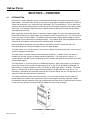
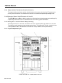
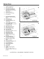
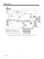
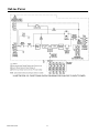
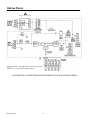

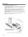
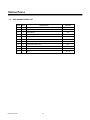
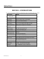
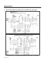
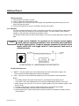
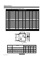
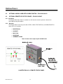
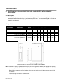
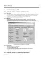
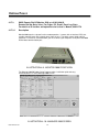
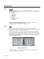
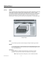
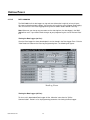
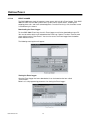

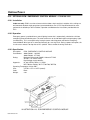
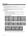
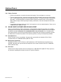
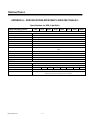
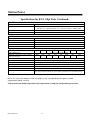
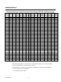

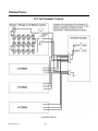
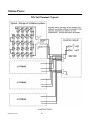
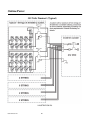
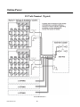
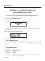
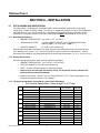
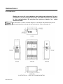
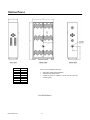
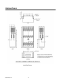
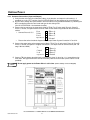
![PROTECTION] 5 E](http://vs1.manualzilla.com/store/data/005801803_1-bb6b523a92d2b05d032451f5b800ca8c-150x150.png)