1
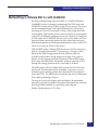
EMC® Host Connectivity Guide
for VMware ESX Server
P/N 300-002-304
REV 45
EMC Corporation
Corporate Headquarters:
Hopkinton, MA 01748-9103
1-508-435-1000
www.EMC.com
Copyright © 2015 EMC Corporation. All rights reserved.
Published November, 2015
EMC believes the information in this publication is accurate as of its publication date. The information is
subject to change without notice.
THE INFORMATION IN THIS PUBLICATION IS PROVIDED “AS IS.” EMC CORPORATION MAKES NO
REPRESENTATIONS OR WARRANTIES OF ANY KIND WITH RESPECT TO THE INFORMATION IN THIS
PUBLICATION, AND SPECIFICALLY DISCLAIMS IMPLIED WARRANTIES OF MERCHANTABILITY OR
FITNESS FOR A PARTICULAR PURPOSE.
Use, copying, and distribution of any EMC software described in this publication requires an applicable
software license.
EMC2, EMC, and the EMC logo are registered trademarks or trademarks of EMC Corporation in the United
State and other countries. All other trademarks used herein are the property of their respective owners.
For the most up-to-date regulator document for your product line, go to EMC Online Support
(https://support.emc.com).
2
EMC Host Connectivity Guide for VMware ESX Server
Contents
Preface............................................................................................................................ 11
Chapter 1
Introduction to VMware Infrastructure/ vSphere
VMware vSphere...............................................................................
vSphere 4.....................................................................................
vSphere 5.....................................................................................
VMware ESX/ESXi Server...............................................................
VMkernel ....................................................................................
Service console ...........................................................................
Useful VMware ESX/ESXi Server utilities and functions ...
Control interface................................................................................
VMware Web UI ........................................................................
VMware vSphere Client ..........................................................
VMware vCenter Server ...........................................................
Connecting EMC storage with ESX/ESXi Server.........................
Chapter 2
18
18
18
19
19
20
21
23
23
23
23
24
Installation of ESX/ESXi Server
Installation .........................................................................................
Installation media ......................................................................
Installation methods..................................................................
Initiator setting and installation .....................................................
Host Bus Adapter (HBA)..........................................................
iSCSI card ...................................................................................
Converged Network Adapter (CNA) .....................................
Adapter installation...................................................................
Install adapter card....................................................................
Recommendations ............................................................................
EMC Host Connectivity Guide for VMware ESX Server
26
26
26
28
28
29
30
31
31
32
3
Contents
Chapter 3
Connectivity
Fibre Channel ....................................................................................
Fabric zoning..............................................................................
VMAX and Symmetrix connectivity.......................................
VNX series and CLARiiON connectivity...............................
iSCSI....................................................................................................
VMware ESX SW iSCSI.............................................................
VMware ESX HW iSCSI ...........................................................
VMAX or Symmetrix connectivity..........................................
VNX series and CLARiiON connectivity...............................
FCoE initiator configurations..........................................................
Configuring Emulex FCoE CNAs with VMware ESX
Server...........................................................................................
Configuring QLogic FCoE CNAs with VMware ESX
Server...........................................................................................
Configuring Brocade FCoE CNAs with VMware ESX
Server...........................................................................................
Cisco Unified Computing System with FCoE .......................
Configuring FCoE for Intel Ethernet Server Adapter with
VMware ESX server ..................................................................
Chapter 4
34
34
34
40
50
51
63
64
67
71
71
80
85
90
92
Array Information and Configuration
VMAX and Symmetrix array configurations................................ 94
Required storage system configuration ................................. 94
Addressing VMAX or Symmetrix devices............................. 94
Required director bit settings for HP-UX 11iv3 (HP-UX
11.31) initiators........................................................................... 98
EMC Symmetrix Management Console (SMC) ................... 99
Recommendations for optimal performance....................... 103
ESX host in the VNX series and CLARiiON environment ....... 106
VNX series and CLARiiON failover modes ....................... 106
Adding the VMware ESX server host to a storage
group ......................................................................................... 109
Performing a VNX series and CLARiiON NDU with
VMware ESX server hosts ...................................................... 110
Manual trespass on VNX series and CLARiiON systems
to recover the original path .................................................... 117
EMC VPLEX .................................................................................... 124
VPLEX documentation ........................................................... 124
Prerequisites ............................................................................. 125
Provisioning and exporting storage ..................................... 125
Storage volumes....................................................................... 128
4
EMC Host Connectivity Guide for VMware ESX Server
Contents
System volumes........................................................................ 130
Required storage system setup .............................................. 131
Required VMAX or Symmetrix FA bit settings................... 131
Supported storage arrays........................................................ 132
Initiator settings on back-end arrays..................................... 133
Host connectivity ..................................................................... 133
Exporting virtual volumes to hosts ....................................... 133
Front-end paths ........................................................................ 138
Configuring VMware ESX hosts to recognize VPLEX
volumes ..................................................................................... 140
EMC XtremIO .................................................................................. 141
Best practices for zoning and subnetting.............................. 141
Configuring a VMware vSphere host ................................... 144
Configuring Fibre Channel HBA........................................... 151
Configuring multipath software............................................ 156
File system and application requirements ........................... 162
Chapter 5
Multipathing in VMware ESX/ESXi Server
Overview .......................................................................................... 168
Path policies .............................................................................. 168
Multipathing in VMware ESX Server with VMAX or
Symmetrix ........................................................................................ 170
Multipathing in VMware ESX 3.x with CLARiiON ................... 171
Native multipathing in VMware ESX/ESXi 4.x and ESXi 5.x .. 172
VMAX or Symmetrix policy ................................................... 172
VNX series and CLARiiON policy ........................................ 172
Multipathing in VMware ESXi/ESX 5.x and ESXi 4.x
with VPLEX............................................................................... 173
ESX Server 4.x........................................................................... 175
ESX/ESXi 4.x and ESXi 5.x ..................................................... 175
PowerPath /VE for VMware ESX/ESXi 4.x and ESXi 5.x......... 177
Major components ................................................................... 178
Supported storage types ......................................................... 178
PowerPath commands............................................................. 179
Claim rules ................................................................................ 180
Appendix A
Migration Considerations
ESX 3.0.x .......................................................................................... 182
ESX 3.5 ............................................................................................. 183
ESX/ESXi 4.x and ESXi 5.x ........................................................... 184
EMC Host Connectivity Guide for VMware ESX Server
5
Contents
Appendix B
Virtual Provisioning
Virtual Provisioning ......................................................................
Terminology .............................................................................
Traditional versus Virtual (thin) Provisioning ...........................
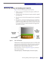
Monitoring, adding, and deleting pool capacity .......................
Virtual LUN architecture and features .......................................
VMware Virtual Machine File System with thin LUN .............
ESX 3.x.......................................................................................
ESX 4.x.......................................................................................
Virtual Provisioning with VNX series and CLARiiON ............
Virtual Provisioning on VMware ESX v3.x .........................
Virtual Provisioning on VMware ESX v4.x .........................
Virtual Provisioning with VMAX or Symmetrix .......................
Main components ....................................................................
Management tools ...................................................................
Virtual Provisioning on EMC VMAX or Symmetrix..........
Implementation considerations ...................................................
Appendix C
Virtual Machine File System
VMFS datastore ..............................................................................
Volume alignment ..........................................................................
Version history ...............................................................................
Size limits ........................................................................................
Appendix D
186
186
188
189
191
193
193
194
195
195
198
208
208
209
210
220
222
223
224
225
Raw Disk Usage and Mapping
Raw disk usage and caveats ......................................................... 228
Raw Device Mappings (RDM) ..................................................... 229
Appendix E
Boot from SAN
Booting from VMAX or Symmetrix storage arrays .................. 232
Booting from VNX series and CLARiiON storage systems .... 234
6
EMC Host Connectivity Guide for VMware ESX Server
Figures
Title
1
2
3
4
5
6
7
8
9
10
11
12
13
14
15
16
17
18
19
20
21
22
23
24
25
26
27
28
29
30
Page
One host, two switches, and one VMAX or Symmetrix array ................. 36
One host, two switches, and four VMAX or Symmetrix arrays .............. 37
SMC Properties verification screen .............................................................. 38
Solution Enabler CLI verification screen .................................................... 39
One host, two switches, and one VNX series or CLARiiON systems .... 42
One host, two switches, and four VNX series or CLARiiON systems ... 43
Connectivity Status dialog ............................................................................ 46
Registering for a failover-enabled environment example ........................ 47
Warning message example ........................................................................... 48
Host reported as attached, but manually registered example ................. 49
SCSI commands encapsulated by Ethernet headers ................................. 50
VMkernel and service console on a single vSwitch .................................. 51
Two NICs on a single vSwitch iSCSI configuration .................................. 57
Two NICs in dual vSwitch iSCSI configuration ........................................ 58
vSwitch configuration .................................................................................... 59
Cisco Unified Computing System example ................................................ 91
SMC interface example .................................................................................. 99
Device Masking and Mapping-Masking dialog box ............................... 100
Masking: Set LUN Addresses dialog box ................................................. 101
Set Port Attributes dialog box .................................................................... 102
Register Initiator Record window .............................................................. 109
Storage Group Properties window ............................................................ 110
Software Installation Wizard ...................................................................... 112
Software Installation Wizard window ...................................................... 113
Non-Disruptive Upgrade Delay window ................................................. 114
Software Package Selection window ......................................................... 116
Software Operation Progress History window ....................................... 117
LUNs example .............................................................................................. 119
View LUN properties .................................................................................. 120
Menu .............................................................................................................. 121
EMC Host Connectivity Guide for VMware ESX Server
7
Figures
31
32
33
34
35
36
37
38
39
40
41
42
43
44
45
8
Confirm trespass LUNs ...............................................................................
Report on LUNs ...........................................................................................
VPLEX provisioning and exporting storage process ..............................
Create storage view .....................................................................................
Register initiators .........................................................................................
Add ports to storage view ..........................................................................
Add virtual volumes to storage view .......................................................
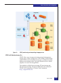
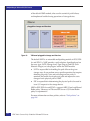
VMkernel pluggable storage architecture ................................................
Traditional storage provisioning ...............................................................
Virtual (thin) provisioning ..........................................................................
Pool % Full Threshold .................................................................................
Reserved capacity .........................................................................................
LUN threshold and allocation limit ..........................................................
Reserved capacity .........................................................................................
Virtual Provisioning on a VMAX or Symmetrix system example ........
EMC Host Connectivity Guide for VMware ESX Server
122
123
127
135
136
137
138
176
188
188
189
190
191
192
208
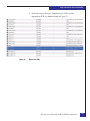
Tables
Title
1
2
3
4
5
6
7
8
9
Page
EMC models and minimum operating system requirements ..................12
Useful utilities and functions for VMware ESX Server 3.x .......................21
Useful utilities and functions for VMware ESX Server 4.x .......................21
Useful utilities and functions for VMware ESXi 5 ......................................22
VMAX or Symmetrix SCSI-3 addressing modes ........................................96
VMAX or Symmetrix director bit setting for ESX Server
environments ....................................................................................................98
Required Symmetrix FA bit settings for connection to VPLEX ..............132
Supported hosts and initiator types ...........................................................140
VMFS/ESX versions .....................................................................................224
EMC Host Connectivity Guide for VMware ESX Server
9
Tables
10
EMC Host Connectivity Guide for VMware ESX Server
Preface
As part of an effort to improve and enhance the performance and capabilities
of its product line, EMC from time to time releases revisions of its hardware
and software. Therefore, some functions described in this document may not
be supported by all revisions of the software or hardware currently in use.
For the most up-to-date information on product features, refer to your
product release notes.
If a product does not function properly or does not function as described in
this document, please contact your EMC representative.
This guide describes the features and setup procedures for VMware
ESX Server host interfaces to EMC Symmetrix, VMAX, VNX, and
CLARiiON storage systems. This document is meant to assist in the
installation and configuration of VMware ESX Server attached to
Symmetrix, VMAX, VNX, and CLARiiON systems.
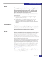
Audience
This guide is intended for use by storage administrators, system
programmers, or operators who are involved in acquiring, managing,
or operating Symmetrix, VMAX, VNX, and CLARiiON, and host
devices.
Readers of this guide are expected to be familiar with the following
topics:
◆
VMAX, Symmetrix, VNX, and CLARiiON system operation
◆
VMware ESX Server operating environment
EMC Host Connectivity Guide for VMware ESX Server
11
Preface
VMAX, Symmetrix,
VNX, and CLARiiON
references
Unless otherwise noted:
◆
Any general references to Symmetrix or Symmetrix array include
the VMAX3 Family, VMAX, and DMX.
◆
Any general references to VNX include VNX5100/5200/5300/
5400/5500/5600/5700/5800/7500/7600/8000.
◆
Any general references to CLARiiON or CLARiiON array include
the FC4700, FC4700-2, CX, CX3, and CX4.
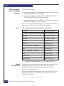
Table 1 lists the minimum EMC Enginuity™ and EMC HYPERMAX™
requirements for EMC VMAX and Symmetrix models.
Table 1
EMC models and minimum operating system requirements
EMC model
Minimum operating system
VMAX 400K a
HYPERMAX 5977.250.189
VMAX 200K a
HYPERMAX 5977.250.189
VMAX 100K a
HYPERMAX 5977.250.189
VMAX 40K
Enginuity 5876.82.57
VMAX 20K
Enginuity 5876.82.57
VMAX 10K (Systems with SN xxx987xxxx)
Enginuity 5876.159.102
VMAX
Enginuity 5876.82.57
VMAX 10K (Systems with SN xxx959xxxx)
Enginuity 5876.82.57
VMAXe®
Enginuity 5876.82.57
Symmetrix DMX-4
Enginuity 5773.79.58
Symmetrix DMX-3
Enginuity 5773.79.58
a. VMAX 400K, VMAX 200K, and VMAX 100K are also referred to as the VMAX3™ Family.
Related
documentation
For the most up-to-date information for supported server and HBA
combinations, always consult the EMC Support Matrix (ESM),
available through E-Lab Interoperability Navigator (ELN) at
http://elabnavigator.EMC.com.
For VMware-specific documentation, such as the VMware ESX Server
Release Notes, ESX Server Administration Guide, and the ESX Server
Installation Guide, go to:
http://www.VMware.com/support
12
EMC Host Connectivity Guide for VMware ESX Server
Preface
For a list of supported guest operating systems, refer to the VMware
Guest Operating System Installation Guide, located at:
http://www.VMware.com/pdf/GuestOS_guide.pdf
Conventions used in
this guide
EMC uses the following conventions for notes and cautions.
Note: A note presents information that is important, but not hazard-related.
IMPORTANT
An important notice contains information essential to operation of
the software.
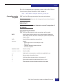
Typographical conventions
EMC uses the following type style conventions in this guide:
Bold
Used for names of interface elements, such as names of windows, dialog boxes,
buttons, fields, tab names, key names, and menu paths, (what the user specifically
selects or clicks)
Italic
Used for full titles of publications referenced in text
Courier
Used for:
• System output, such as an error message or script
• System code
• Pathnames, filesnames, prompts, and syntax
• Commands and options
Courier bold
Used for user input.
Courier italic
Used for variables.
<>
Angle brackets enclose parameter or variable values supplied by the user
[]
Square brackets enclose optional values
|
Vertical bar indicates alternate selections - the bar means “or”
{}
Braces indicate content that you must specify (that is, x or y or z)
...
Ellipses indicate nonessential information omitted from the example
EMC Host Connectivity Guide for VMware ESX Server
13
Preface
Where to get help
EMC support, product, and licensing information can be obtained as
follows.
EMC support, product, and licensing information can be obtained on
the EMC Online Support site as described next.
Note: To open a service request through the EMC Online Support site, you
must have a valid support agreement. Contact your EMC sales representative
for details about obtaining a valid support agreement or to answer any
questions about your account.
Product information
For documentation, release notes, software updates, or for
information about EMC products, licensing, and service, go to the
EMC Online Support site (registration required) at:
https://support.EMC.com
Technical support
EMC offers a variety of support options.
Support by Product — EMC offers consolidated, product-specific
information on the Web at:
https://support.EMC.com/products
The Support by Product web pages offer quick links to
Documentation, White Papers, Advisories (such as frequently used
Knowledgebase articles), and Downloads, as well as more dynamic
content, such as presentations, discussion, relevant Customer
Support Forum entries, and a link to EMC Live Chat.
EMC Live Chat — Open a Chat or instant message session with an
EMC Support Engineer.
eLicensing support
To activate your entitlements and obtain your Symmetrix license files,
visit the Service Center on https://support.EMC.com, as directed on
your License Authorization Code (LAC) letter e-mailed to you.
For help with missing or incorrect entitlements after activation (that
is, expected functionality remains unavailable because it is not
licensed), contact your EMC Account Representative or Authorized
Reseller.
For help with any errors applying license files through Solutions
Enabler, contact the EMC Customer Support Center.
14
EMC Host Connectivity Guide for VMware ESX Server
Preface
If you are missing a LAC letter, or require further instructions on
activating your licenses through the Online Support site, contact
EMC's worldwide Licensing team at [email protected] or call:
◆
North America, Latin America, APJK, Australia, New Zealand:
SVC4EMC (800-782-4362) and follow the voice prompts.
◆
EMEA: +353 (0) 21 4879862 and follow the voice prompts.
We'd like to hear from you!
Your suggestions will help us continue to improve the accuracy,
organization, and overall quality of the user publications. Send your
opinions of this document to:
[email protected]
EMC Host Connectivity Guide for VMware ESX Server
15
Preface
16
EMC Host Connectivity Guide for VMware ESX Server
1
Invisible Body Tag
Introduction to
VMware Infrastructure/
vSphere
This chapter provides information about the VMware infrastructure
vSphere, including:
◆
◆
◆
◆
VMware vSphere................................................................................
VMware ESX/ESXi Server.....................................................................
Control interface......................................................................................
Connecting EMC storage with ESX/ESXi Server..........................
18
19
23
24
Note: In this document, Virtual Infrastructure (VI) and vSphere are used
interchangeably.
Introduction to VMware Infrastructure/ vSphere
17
Introduction to VMware Infrastructure/ vSphere
VMware vSphere
VMware has renamed its infrastructure product to vSphere. The
following versions are briefly discussed in this section:
◆
“vSphere 4” on page 18
◆
“vSphere 5” on page 18
vSphere 4
VMware vSphere 4 is the industry’s first cloud operating system,
transforming IT infrastructures into a private cloud, a collection of
internal clouds federated on-demand to external clouds, delivering IT
infrastructure as a service.
vSphere 4 supports 64-bit VMkernel and service console. The service
console version is derived from a release of a leading enterprise
Linux vendor.
vSphere 5
VMware vSphere 5 supports virtual machines (VMs) that are up to
four times more powerful than previous versions with up to 1
terabyte of memory and 32 virtual CPUs. These VMs are able to
process in excess of 1 million I/O operations per second. When
combined with VMware vSphere 5's enhanced, simplified High
Availability, performance, and availability is greatly improved.
VMware vSphere 5 also supports the automated approach to manage
data center resources, including server deployment and storage
management. Customers define policies and establish the operating
parameters, and VMware vSphere 5 does the rest. The three key
features to enable the automated processes are:
18
◆
Auto-Deploy
◆
Profile-Driven Storage
◆
Storage DRS
EMC Host Connectivity Guide for VMware ESX Server
Introduction to VMware Infrastructure/ vSphere
VMware ESX/ESXi Server
VMware ESX Server is the main building block of the VMware
infrastructure. It provides a platform for multiple virtual machines
sharing the same hardware resources, (including processor, memory,
storage, and networking resources), the ability to perform all the
functions of a physical machine. This maximizes the hardware
utilizing efficiency while minimizing installation capital and
operating cost.
VMware ESX Server consists of two main components, discussed
briefly in this section:
◆
“VMkernel” on page 19
◆
“Service console” on page 20
◆
“Useful VMware ESX/ESXi Server utilities and functions” on
page 21
The interaction between them forms a dynamic and reliable
virtualized environment, providing virtual machines with high
availability, resource management, operational automation and
security features that improve service quality levels even to the most
resource-intensive mission-critical applications.
VMkernel
The ESX Server virtualized layer, VMkernel, runs on bare metal,
handling CPU and memory directly without going through a
third-party operating system. VMkernel uses Scan-Before-Execution
(SBE) to handle special or privileged CPU instructions.
To access other hardware, including network and storage devices,
vmkernel modules are used. Some of the modules are derived from
the Linux kernel modules.
VMkernel can provide services including CPU scheduling, memory
management and virtual switch data processing for virtual machines
to access the underlying physical hardware of the server, where they
are built on.
VMkernel manages all the operating systems on the machine,
including both the service console and the guest operating systems
running on each virtual machine.
VMware ESX/ESXi Server
19
Introduction to VMware Infrastructure/ vSphere
VMkernel is usually interfaced with three major components:
hardware, guest operating system, and the service console.
Service console
The Service Console is available only with ESX, not with ESXi. Until
vSphere 4, both ESX and ESXi were available. vSphere 5 is only
available with ESXi.
vSphere 4
The service console gives access to VMkernel, and thus can provide
management services, including firewall, Simple Network
Management Protocol (SNMP) agents, and a web server to the ESX
Server and the virtual machines built on the server.
For remote access to the service console by a root user through ssh
client software, such as Putty, can be enabled. The root user can
modify settings for ssh, Telnet, and FTP using the security
configuration page in the management interface
(http://<servername>/security-config), or edit the ssh configuration
file directly through service console.
It is recommended that you not run resource-consuming tasks on the
service console since it competes with other virtual machines for
processor cycles in VMkernel scheduling.
vSphere 5
With the Service Console removed, vSphere 5 has a reduced
hypervisor code-base footprint (less than 150 MB vs. ESX's 2 GB).
vSphere 5 completes the ongoing trend of migrating management
functionality from the local command line interface to remote
management tools.
With vSphere 5, instead of using the Service console, VMware created
remote command lines, such as the vSphere Command Line Interface
(vCLI) and PowerCLI, to provide command and scripting capabilities
in a more controlled manner. These remote command line sets
include a variety of commands for configuration, diagnostics and
troubleshooting. For low-level diagnostics and the initial
configuration, menu-driven and command line interfaces are
available on the local console of the server.
20
EMC Host Connectivity Guide for VMware ESX Server
Introduction to VMware Infrastructure/ vSphere
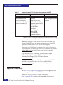
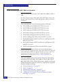
Useful VMware ESX/ESXi Server utilities and functions
This section describes useful utilities and functions for ESX Server
3.x, 4.x, and ESXi 5.
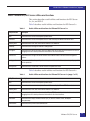
Table 2 describes useful utilities and functions for ESX Server 3.x.
Table 2
Useful utilities and functions for VMware ESX Server 3.x
Utility/Function
Description
fdisk
Command used to create and manipulate partition tables.
vmkfstools
Command used to create and manipulate files on LUNs owned by the VMware ESX Server host.
vmkload_mod
Command used to view, load, remove driver modules in the VMkernel.
vmkdump
Command used to manage the VMkernel’s dump partition.
vm-support
Command used to gather information about the VMware ESX Server itself and virtual machines to assist in
debugging issues or to obtain performance information for the virtual machines.
vmkiscsi-tool
Command used to configure the iSCSI software and hardware initiators and basic iSCSI management
functions.
esxcfg-mpath
Command used to list all or specific paths on the system with its detailed information or to specify a specific
path for operations.
esxcfg-rescan
Command used to rescan HBA or iSCSI initiators and update their status.
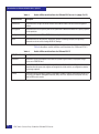
Table 3 describes useful utilities and functions for ESX Server 4.x.
Table 3
Useful utilities and functions for VMware ESX Server 4.x (page 1 of 2)
Utility/Function
Description
fdisk
Command used to create and manipulate partition tables.
vmkfstools
Command used to create and manipulate files on LUNs owned by the VMware ESX Server host.
vmkload_mod
Command used to view, load, remove driver modules in the VMkernel.
vm-support
Command used to gather information about the VMware ESX Server itself and virtual machines to assist in
debugging issues or to obtain performance information for the virtual machines.
vmkvsitools
Command used to display information about lspci, ps, hwclock, VMware, hwinfo, bootOption,
vmksystemswap.
vmkisciadmin
Command used to perform iSCSI administration.
VMware ESX/ESXi Server
21
Introduction to VMware Infrastructure/ vSphere
Table 3
Useful utilities and functions for VMware ESX Server 4.x (page 2 of 2)
Utility/Function
Description
vmkiscsi-tool
Command used to configure the iSCSI software and hardware initiators and basic iSCSI management
functions.
esxcfg-mpath
Command used to list all or specific paths on the system with its detailed information or to specify a specific
path for operations.
esxcfg-rescan
Command used to rescan HBA or iSCSI initiators and update their status.
esxcli
Command used to set the path policy, mask paths, preview and manage third-party storage arrays.
Command can also be used to manage iSCSI NIC bindings.
Table 4 describes useful utilities and functions for VMware ESXi 5.
Table 4
22
Useful utilities and functions for VMware ESXi 5
Utility/Function
Description
vmkfstools
Command to create and manipulate virtual disks, file systems, logical volumes, and physical storage
devices on an ESX/ESXi host.
vmware-cmd
Command to provide an interface to perform operations on a virtual machine, including to retrieve
information about the power state, register and unregister the virtual machine, set configuration variables,
and manage snapshots.
resxtop
Command to retrieve performance statistics. Command is included in vSphere command line interface (CLI)
and is part of the vSphere Management Assistant (vMA), which is an equivalent to esxtop that runs only
inside an ESX service console.
EMC Host Connectivity Guide for VMware ESX Server
Introduction to VMware Infrastructure/ vSphere
Control interface
This section briefly describes the following:
◆
◆
◆
“VMware Web UI” on page 23
“VMware vSphere Client ” on page 23
“VMware vCenter Server” on page 23
VMware Web UI
VMware Web UI is a free option allowing administrators to monitor
or manage the server remotely through a web-based graphical
interface by simply typing the host IP in an internet browser window
and logging on using an administrator password. One of the main
disadvantages of VMware Web UI, compared with VI Client, is that
only one ESX server can be accessed at a time.
VMware vSphere Client
vSphere Client is a graphical user interface that allows the remote
connection from administrators and users of different roles to the
VirtualCenter Management Server or individual ESX Server
installations from any Windows platform. For more information on
vSphere, refer to “VMware vSphere” on page 18.
VMware vCenter Server
Upon release of vSphere 4.0, VMware VirtualCenter is renamed to be
vCenter Server. VMware vCenter Server is a scalable and extensible
platform to manage a virtualized environment.
vCenter Server is a Windows Service running automatically in the
background, monitoring and managing activities even when VI /
vSphere Clients are disconnected or not in use. VirtualCenter can
manage more than one host and it must be accessible by each host
and machines running the Virtual Infrastructure / vSphere Client.
Generally, new versions of VirtualCenter/vCenter Server can be
compatible with its previous versions, while it is not valid vice versa.
For the details of ESX, vCenter Server, and vSphere Client version
compatibility, refer to the vSphere Compatibility Matrices available at
http://www.VMware.com.
Control interface
23
Introduction to VMware Infrastructure/ vSphere
Connecting EMC storage with ESX/ESXi Server
To add or remove EMC® storage devices to or from an ESX/ESXi
Server, complete the following steps:
1. Modify the EMC storage array configuration appropriately using
storage management tools.
Applicable storage configurations include:
• LUN masking
• Creation and assignment of LUNs and mataLUNs to the Fibre
Channel ports that used by VMware ESX/ESXi Server
Storage management tools include:
• GUI-based management interface for EMC VNX® series and
CLARiiON® storage
• EMC Symmetrix® Management Console for VMAX and
Symmetrix storage
• Command line based CLI for VNX series and CLARiiON
storage
• Solution Enabler for VMAX and Symmetrix storage
2. After changing the configuration, rescan the host /initiator
adapter ports to update the changes made in Step 1.
To do this, choose one of the following methods:
• Reboot the VMware ESX/ESXi Server
• Rescan HBA port in vSphere Client
• Execute the esxcfg-rescan command in the VMware
ESX/ESXi Server or in any other remote access software client,
such as PuTTY
24
EMC Host Connectivity Guide for VMware ESX Server
2
Invisible Body Tag
Installation of ESX/ESXi
Server
This chapter covers installation and setting information for the
VMware ESX Server 3.x and 4.x, and VMware ESX Server ESXi 5,
including:
◆
◆
◆
Installation........................................................................................... 26
Initiator setting and installation ...................................................... 28
Recommendations ............................................................................. 32
Installation of ESX/ESXi Server
25
Installation of ESX/ESXi Server
Installation
This section contains the following information:
◆
“Installation media” on page 26
◆
“Installation methods” on page 26
Installation media
CD-ROM
ESX Server can be installed directly from a CD-ROM into a physical
server. ESX 4.x requires a DVD disk with larger size.
ISO image
The ISO image can be loaded through a virtual CD-ROM.
IMPORTANT
ESX Server only supports installation with x 86 architecture servers.
Installation methods
The following are installation methods:
◆
Graphical mode
User can install ESX through graphical instructions.
◆
Text mode
ESX is installed by reading text options and giving commands.
◆
Script install
This appears in ESX 4.x and ESXi 5, which is used for quick install
on first hard drive or deployment on multiple servers in a shorter
time.
Refer to the following sections for specific recommendations for the
following versions:
26
◆
“ESX 3.x ” on page 27
◆
“ESX 4.x” on page 27
◆
“ESXi 5” on page 27
EMC Host Connectivity Guide for VMware ESX Server
Installation of ESX/ESXi Server
ESX 3.x
Note: For the installation of ESX 3.x and ESX 4.x, there are default partition
sizes. It is recommended you use the default sizes.
ESX 3.x is based on 32-bit modified Red Hat version 2.4.21 or newer
kernel.
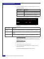
ESX 4.x
/boot
101 MB
primary
swap
544 MB
primary
/
5 GB
primary
/var/log
2 GB
Note: For the installation of ESX 3.x and ESX 4.x, there are default partition
sizes. It is recommended you use the default sizes.
ESX 4.x is based on the Red Hat Linux kernel, which is a 64-bit
system. The default service console partition information is as
follows:
ESXi 5
/boot
1.10 GB
primary
swap
600 MB
primary
/
5 GB
primary
/var/log
2 GB
All freshly installed hosts in vSphere 5 use the GUID Partition Table
format instead of the MSDOS-style partition label. This change
supports ESXi installation on disks larger than 2 TB.
Newly installed vSphere 5 hosts use VMFS5, an updated version of
the VMware File System for vSphere 5. Unlike earlier versions, ESXi 5
does not create VMFS partitions in second and successive disks.
Upgraded systems do not use GUID Partition Tables (GPT), but
retain the older MSDOS-based partition label.
Note: Partitioning for hosts that are upgraded to ESXi 5 differs significantly
from partitioning for new installations of ESXi 5. Refer to the vSphere
Upgrade documentation at http://www.VMware.com/support/pubs.
Installation
27
Installation of ESX/ESXi Server
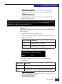
Initiator setting and installation
VMware supports QLogic-, Emulex-, and Brocade-based Fibre
Channel host bus adapters with EMC storage. Refer to EMC Support
Matrix for the most up-to-date supported HBA models.
Both the QLogic iSCSI hardware initiator and the generic networked
interface card (NIC) iSCSI software initiator are supported with EMC
iSCSI storage arrays. Refer to the Linux "iSCSI Connectivity" section
of the EMC Support Matrix for supported configurations and required
driver revision levels.
An EMC-published QLogic iSCSI guide is available on the QLogic
website. Native iSCSI release notes are available on
http://support.EMC.com.
This section provides information on the following:
◆
“Host Bus Adapter (HBA)” on page 28
◆
“iSCSI card ” on page 29
◆
“Converged Network Adapter (CNA)” on page 30
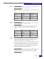
Host Bus Adapter (HBA)
The Fibre Channel HBA driver functions as a device driver layer
below the standard VMware SCSI adapter driver. The Fibre Channel
interface is therefore transparent to the VMware disk administration
system.
Fibre Channel Rate
2 GB/s
4 GB/s
8 GB/s
I/O Bus
PCI
PCI-X 1.0/2.0
PCI-E 1.0a/1.1/2.0
FC Ports
Single
Dual
Quad
There are legacy cards with speed of 1 GB/s; however these cards
were used with earlier versions of ESX. It is recommended to use 4
GB or 8 GB HBA cards starting at ESX 3.x and later to achieve better
performance.
To check QLogic HBA parameters, issue the following command:
# /proc/scsi/qlaxxx/N
28
EMC Host Connectivity Guide for VMware ESX Server
Installation of ESX/ESXi Server
◆
For Emulex HBAs
# /proc/scsi/lpfcxxx/N
◆
For Brocade HBAs
# /proc/scsi/bfaxxx/N
where N is the sequential value of each QLogic HBA installed in
the system, beginning with the number after the last host adapter
number entry in the file.
The parameters contain useful information of the initiator, the
major information including:
• HBA Model Number
• Driver Version
• Firmware Version
• BIOS Version
• Current Speed
• Link Down Timeout Value
• Port Down Retry Times
• WWPN/WWNN of initiator
• WWPN/WWNN of the target being connected
Normally the timeout value for link down events is 30 seconds. To
change the parameters of the HBAs, use utilities like SAN Surfer for
QLogic and HBAnywhere for Emulex. Both offer the graphical
interface and command line interface.
Note: EMC supports fabric boot with VMware ESX Server v2.5.x and later
using the QLogic or Emulex HBAs.
Virtual Machines are recommended to boot over the fabric.
iSCSI card
EMC supports both the hardware QLogic iSCSI HBA and the
software generic NIC iSCSI HBA, in conjunction with EMC iSCSI
storage arrays on the VMware platform.
Initiator setting and installation
29
Installation of ESX/ESXi Server
Note: This example uses QLogic HBAs. The card names are slightly different
for other brands.
All hardware iSCSI HBAs have 1 Gb/s throughput rate. Cards may
have single ports or dual ports.
To check the parameters, issue the following command:
# cat/proc/scsi/qlaxxx/N
where N is the sequential value of each HBA installed in the system,
beginning with the number after the last host adapter number entry
in the file.
The parameters contain useful information of the initiator, the major
information including:
◆
iSCSI Model Number
◆
Driver Version
◆
Firmware Version
◆
IP specification
◆
IQN of initiators
◆
IQN of targets
The parameters can be changed through QLogic SAN Surfer
management utility.
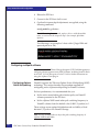
Converged Network Adapter (CNA)
EMC is now supporting Fibre Channel over Ethernet (FCoE)
Converged Network Adapter (CNA) offerings with VMware ESX
Servers. FCoE adapters represent a method to converge both Fibre
Channel and Ethernet traffic over a single physical link to a switch
infrastructure that manages both storage (SAN) and network (IP)
connectivity within a single unit.
Currently supported FCoE Converged Network Adapter (CNA)
offerings are:
30
◆
Emulex LP21000 and LP21002
◆
QLogic QLE8042
EMC Host Connectivity Guide for VMware ESX Server
Installation of ESX/ESXi Server
Currently, the VMware ESX Server versions that support Fibre
Channel over Ethernet are ESX Server 3.5 Update 2 and later and ESX
4.0 and later.
Always refer to the EMC Support Matrix to verify which servers are
supported in FCoE configurations with ESX Server.
Fiber Channel Rate
4 G/s
I/O Rate
10 G/s
I/O Bus
PCI-E
FC Ports
Single
Dual
You may customize the installation according to your server and the
amount of memory and hard disk space you have.
Adapter installation
EMC supports all the in-box drivers come with the different
versions of ESX Server. From ESX 3.x and later versions, there is no
need to manually load the adapter driver into system. ESX will detect
the hardware and load the driver automatically.
For driver version information, refer to EMC Support Matrix or the
VMware Hardware Compatibility Guide.
Install adapter card
When choosing an adapter for your server, it is important to know
which adapter is compatible with your server’s PCI/PCI-X/PCI
Express slots. Certain adapter models have specific voltage
requirements or physical limitations that allow them to only work in
specific slots. There are three general steps to install a card on the
server.
1. Open the server cover.
2. Insert the adapter with correct direction into PCI slot.
3. Connect the Fiber/Ethernet/Twinax cables for FC HBA/iSCSI
HBA/CNA with one end connecting to adapter port and the
other end to the connector on the storage system or a hub/switch
port.
Initiator setting and installation
31
Installation of ESX/ESXi Server
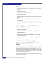
Recommendations
The following are a few recommendations for the installation:
◆
Use static IP addresses.
◆
Set the hardware clock when prompted.
◆
Create at least one user account other than root.
Note: emacs, samba, and NFS are not enabled by default in the Console
OS.
◆
Reboot the system after completing the installation.
• For VMware ESX Server v3.x installations, when the system
reboots, you are prompted with three options boot prompt:
esx, service console, debugging mode
The default boot image for VMware ESX Server v2.5.x is esx.
• For ESX 4.x, there are two option
◆
32
– VMware ESX 4.x, Troubleshooting mode
– Default boot, VMware ESX 4.x.
HBAs installed in the ESX server do not require changes on
parameters in the BIOS. Keep the default BIOS and NVRAM
settings for HBAs.
EMC Host Connectivity Guide for VMware ESX Server
Invisible Body Tag
3
.
Connectivity
This chapter provides HBA and iSCSI configuration information for
the VMware ESX Server with VMAX and Symmetrix and VNX series
and CLARiiON systems.
◆
◆
◆
Fibre Channel...................................................................................... 34
iSCSI ..................................................................................................... 50
FCoE initiator configurations ........................................................... 71
Connectivity
33
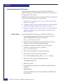
Connectivity
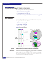
Fibre Channel
Fibre Channel, or FC, is a gigabit speed network technology. A Fibre
Channel SAN is a collection of Fibre Channel nodes that
communicate with each other, typically through fibre-optic media.
Node
A node is defined as a member of the Fibre Channel network. A node
is provided a physical and logical connection to the network by a
physical port on a Fibre Channel switch. Every node requires the use
of specific drivers to access the network.
Fabric switches
Fibre Channel nodes communicate with each other through one or
more Fibre Channel switches, also called fabric switches. The primary
function of a fabric switch is to provide a physical connection and
logical routing of data frames between the attached devices.
Fabric zoning
With ESXi hosts, use a single-initiator zoning or a
single-initiator-single-target zoning. Single-initiator-single-target is
the preferred zoning practice.
IMPORTANT
EMC does not support multi-initiator zones in a VMware ESX
Server fabric environment.
Zoning should be performed on the fabric by creating zone sets that
contain the initiator and the target(s).
VMAX and Symmetrix connectivity
Note: Refer to the EMC Support Matrix or contact your EMC representative
for the latest information on qualified hosts, host bus adapters, and
connectivity equipment.
The VMAX and Symmetrix system is configured by an EMC
Customer Engineer via the VMAX and Symmetrix service processor.
34
EMC Host Connectivity Guide for VMware ESX Server
Connectivity
The EMC Customer Engineer (CE) should contact the EMC
Configuration Specialist for updated online information. This
information is necessary to configure the VMAX or Symmetrix
system to support the customer’s host environment.
After the EMC CE has assigned target IDs and LUNs and brought the
VMAX or Symmetrix channel and disk directors online, reboot the
network operating systems, and go into the configuration program.
Note: All qualified HBAs are listed in the EMC Support Matrix.
Note that the VMware ESX Server installer will recognize LUNs 25
MB or less as management LUNs. This includes any gatekeepers
assigned to the VMware host via Solutions Enabler.
Two possible configuration scenarios are described in the following
two examples:
Example 1
◆
“Example 1” on page 35
◆
“Example 2” on page 36.
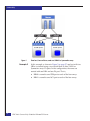
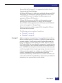
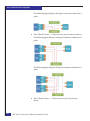
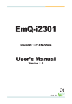
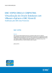
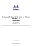
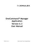
In this example as shown in Figure 1 on page 36, one host with two
HBAs is attached to one VMAX or Symmetrix array using two
separate switches. The zones should be composed of a single initiator
and a single target so they would be created with one HBA and on FA
port.
In this particular example, two switches are used. Using only one
switch is supported, but such a configuration would lack
redundancy. Preferably, a minimum of two switches should be used
to add another level of redundancy. Alternatively, for additional
redundancy, two separate fabrics could be utilized.
Fibre Channel
35
Connectivity
Figure 1
Example 2
36
One host, two switches, and one VMAX or Symmetrix array
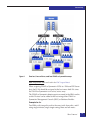
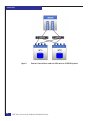
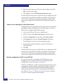
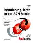
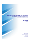
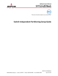
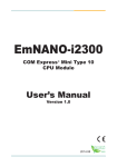
In this example, as shown in Figure 2 on page 37, one host with two
HBAs is attached using a two-switch fabric to four VMAX or
Symmetrix arrays FA ports. In this configuration, the zones are
created with one HBA and one FA port. That is,
◆
HBA0 is zoned to one 15D0 port on each of the four arrays.
◆
HBA1 is zoned to one 16C1 port on each of the four arrays.
EMC Host Connectivity Guide for VMware ESX Server
Connectivity
Figure 2
One host, two switches, and four VMAX or Symmetrix arrays
Note: All qualified HBAs are listed in the EMC Support Matrix.
When assigning VMAX or Symmetrix LUNs to a VMware ESX Server
host, the LUNs should be assigned to the host across both FAs since
the VMAX or Symmetrix is an active/active array.
The VMAX or Symmetrix director ports are zoned to the HBAs on the
switch. Devices can be added to the host using either VMAX or
Symmetrix Management Console (SMC) or Solutions Enabler.
Example for 4.x
Two HBAs with two paths each to the array totals four paths, and if
using single initiator/single target zoning, there are four zones.
Fibre Channel
37
Connectivity
Note: It is recommended to choose "rule of 17" for VMAX or Symmetrix
connectivity (choose two FAs that add up to 17).
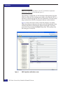
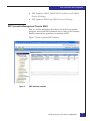
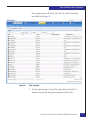
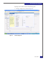
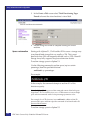
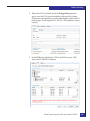
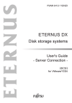
Once zoning is completed, use the Symmetrix Management Console
(SMC) to verify that the initiators are visible on the console. SMC is a
tool that is used to manage the VMAX or Symmetrix. It can be used to
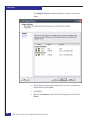
map and mask the VMAX or Symmetrix devices to the initiators.
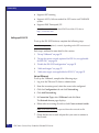
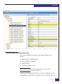
Figure 3 shows the screen used to verify the initiators are visible.
When the initiator is chosen on the pane on the left-hand side of this
window, the details of the initiator appear on the right. You must
ensure that the parameter On Fabric shows Yes. This confirms that
the zoning was successful.
Figure 3
38
SMC Properties verification screen
EMC Host Connectivity Guide for VMware ESX Server
Connectivity
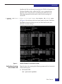
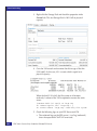
Another tool that can be used to monitor the VMAX or Symmetrix is
Solutions Enabler which, unlike the SMC, uses a command line
interface (CLI). Once the tool is installed on the ESX Server, the
following command can be used to verify that the zoning was
successful:
# symmask -sid <last 3 digits of the symm frame> list logins -dir <dir#> -port
<port#>
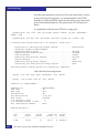
In Figure 4, the initiators that have been zoned are listed. Under the
On Fabric column heading you must see Yes listed beside your
initiators to verify zoning.
Figure 4
Verification of zoning
from initiator side
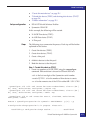
Solution Enabler CLI verification screen
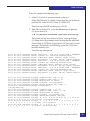
From the host side, running the following commands lists the details
of the initiator ports:
◆
For Emulex HBA:
#cat /proc/scsi/lpfcdd/N
Fibre Channel
39
Connectivity
◆
For QLogic HBA:
#cat /proc/scsi/qla2xxx/N
where N indicates the file for each adapter in the system
These commands also lists the WWNs and WWPNs of the array ports
that the host has been zoned to.
For example:
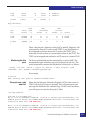
@@@@@ cat /proc/scsi/lpfc820/6
Emulex LightPulse Fibre Channel SCSI driver 8.2.0.30.49vmw
Emulex LP21000-M 10GE PCIe FCoE Adapter on PCI bus 0b device 00 irq 137
BoardNum: 0
Firmware Version: 1.00A5 (A3D1.00A5)
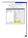
Portname: 10:00:00:00:c9:3c:f8:1c
Nodename: 20:00:00:00:c9:3c:f8:1c
SLI Rev: 3
NPIV Supported: VPIs max 100
RPIs max 512 RPIs used 7
VPIs used 0
Vport List:
Link Up - Ready:
PortID 0x230015
Fabric
Current speed 4G
Physical Port Discovered Nodes: Count 2
t01 DID 241b00 State 06 WWPN 50:06:04:82:d5:f0:c8:d1 WWNN 50:06:04:82:d5:f0:c8:d1
t00 DID 282d00 State 06 WWPN 50:06:04:82:d5:f0:c8:de WWNN 50:06:04:82:d5:f0:c8:de
The WWPNs and WWNs of the array ports are bolded.
VNX series and CLARiiON connectivity
Note: Refer to the EMC Support Matrix or contact your EMC representative
for the latest information on qualified hosts, host bus adapters, and
connectivity equipment.
EMC Access Logix™ must be installed on the VNX series and
CLARiiON storage system to which the VMware ESX Server is being
attached.
VMware ESX Server uses the Linux version of the Navisphere Agent
CLI. The Naviagent must be loaded on the Service Console of the ESX
40
EMC Host Connectivity Guide for VMware ESX Server
Connectivity
Server while the Naviagent CLI is supported on both the Service
Console and the Virtual Machines.
In VMware ESX Server 4.x, both native multipath software and EMC
PowerPath®/VE automatically perform registration to VNX series
and CLARiiON systems. Unisphere/Navisphere Agent is not
required on VMware ESX Server 4.x.
VMware ESX Server owns the HBAs, not the operating systems
running in the virtual machines. As a result, the VMware ESX
Server's HBAs will be registered on the VNX series and CLARiiON
system and assigned to a Storage Group.
The virtual machines will be assigned LUNs through the VMware
ESX Server Service Console.
The following are two examples of zoned hosts:
Example 1
◆
“Example 1” on page 41
◆
“Example 2” on page 43
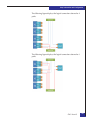
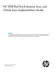
In this example, as shown in Figure 5 on page 42, one host with two
HBAs is attached to one VNX series or CLARiiON system using two
separate switches. Two SP ports on each SP within the systems are
being used. HBA0 is zoned to SPA0 and to SPB1. HBA1 is zoned to
SPA1 and to SPB0. The zones should be composed of a single initiator
and a single target so they would be created with one HBA and on SP
port. Two HBAs with two paths each to the systems totals four paths
and if using single initiator/single target zoning, there are four zones.
In this particular example, two switches are used. Using only one
switch is supported, but such a configuration would lack
redundancy. Preferably, a minimum of two switches should be used
as this adds another level of redundancy. Alternatively, for additional
redundancy, two separate fabrics can be utilized.
Fibre Channel
41
Connectivity
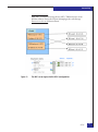
Figure 5
42
One host, two switches, and one VNX series or CLARiiON systems
EMC Host Connectivity Guide for VMware ESX Server
Connectivity
Example 2
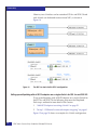
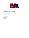
Figure 6
In this example as shown in Figure 6, one host with two HBAs is
attached using a two-switch fabric to four VNX series or CLARiiON
system SPs. In this configuration, the zones are created with one HBA
and one SP port. For instance:
◆
HBA0 is zoned to one SPA port on each of the four systems.
◆
HBA1 is zoned to one SPB port on each of the four systems.
One host, two switches, and four VNX series or CLARiiON systems
Note: All qualified HBAs are listed in the EMC Support Matrix.
When assigning VNX series or CLARiiON LUNs to a VMware ESX
Server host, the LUNs may be assigned to only one SP or their
assignments may be split between the two SPs. Either configuration
is valid.
Fibre Channel
43
Connectivity
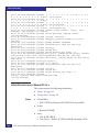
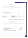
Identifying the WWNs of the HBAs
Consider the following methods:
◆
The recommended method to discover WWNs is to run the
wwpn.pl command for either QLogic or Emulex HBAs. For each
vmhba instance, the wwpn.pl will provide the corresponding
QLogic or Emulex WWPNs.
For example:
[root@l82bi199 /]# /usr/sbin/wwpn.pl
vmhba2: 210000e08b0910a7 (QLogic) 6:1:0
vmhba3: 210100e08b2910a7 (QLogic) 6:1:1
◆
An alternate method to obtain Emulex HBAs’ initiator and target
information is to refer to /proc/scsi/lpfcdd/N (where N
indicates the file for each adapter in the system) when the driver
is loaded. By grep’ing the file(s), the necessary information to
register to host will be reported.
grep the file to obtain the initiator and target information.
For example,
grep DID /proc/scsi/lpfcdd/1
produces output similar to the following for the first Emulex
HBA:
lpfc0t00 DID 060300 WWPN 50:06:01:61:10:60:12:5c WWNN 50:06:01:60:90:60:12:5c
lpfc0t01 DID 060400 WWPN 50:06:01:69:10:60:12:5c WWNN 50:06:01:60:90:60:12:5c
◆
When using QLogic HBAs, the same information is logged in
/proc/scsi/qla2x00/N (where N indicates the file for each
adapter in the system) when the driver is loaded.
grep the file to obtain the initiator and target information.
For example, for a host with QLA23xx HBAs:
grep scsi-qla /proc/scsi/qla2300/0
produces output similar to the following for the first QLogic
HBA:
scsi-qla0-adapter-node=200000e08b0910a7;
scsi-qla0-adapter-port=210000e08b0910a7;
scsi-qla0-target-0=5006016810601270;
scsi-qla0-target-1=5006016010601270;
scsi-qla0-target-2=50060160082012bb;
scsi-qla0-target-3=50060169082012bb;
44
EMC Host Connectivity Guide for VMware ESX Server
Connectivity
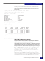
Now that the WWNs have been identified, the VMware ESX Server
host can be registered to the VNX series or CLARiiON system.
The following section will describe the manual registration process.
Manually register the host
In order to manually register the host on the VNX series or
CLARiiON system, perform the following steps:
1. Start the management interface in a web browser on a host to be
used for management purposes.
2. Select the Storage tab so that the arrays being managed by the
management interface are displayed.
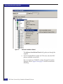
3. Right-click on the appropriate array and select the Connectivity
Status option.
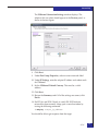
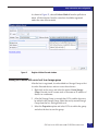
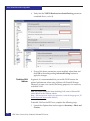
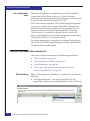
4. The Connectivity Status dialog for that array will show the
Initiator WWNs for each host logged into the array.
An example of the Connectivity Status dialog box can be seen in
Figure 7 on page 46.
Fibre Channel
45
Connectivity
Figure 7
Connectivity Status dialog
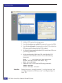
5. In order to manually register your host’s HBAs, select the WWN
of the HBA and click on Register.
You will be prompted to add the server information, such as the
server name and IP address.
Repeat this step for each HBA instance for this VMware ESX
Server host. This will register this HBA or HBAs for your
VMware host.
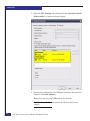
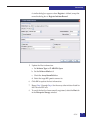
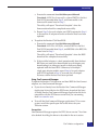
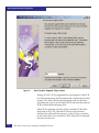
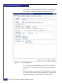
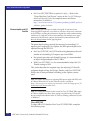
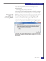
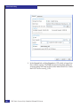
6. Another dialog, Register Initiator Record, appears. When
attaching a VMware ESX Server to a VNX series and CLARiiON,
the standard. For a failover-enabled environment, the required
settings are as follows:
•
•
•
•
46
Initiator Type: CLARiiON Open
ArrayCommPath: Enabled
FailOverMode: 1
Unit Serial Number:Array
EMC Host Connectivity Guide for VMware ESX Server
Connectivity
Note that the failover functionality referred to here is the native
failover functionality incorporated into the VMkernel, not
PowerPath. PowerPath is not available for the VMkernel.
Figure 8 on page 47 shows an example of registering for a
failover-enabled environment.
Note: The box for the ArrayCommPath parameter is checked and the
Failover Mode is set to 1.
Figure 8
Registering for a failover-enabled environment example
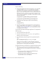
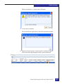
Because no Naviagent is used on the VMware ESX Server, you
will receive a warning message when registering the host.
Figure 9 on page 48 shows an example of the warning message.
Fibre Channel
47
Connectivity
Figure 9
Warning message example
Because the Naviagent is not being used, this warning is to be
expected and is acceptable.
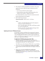
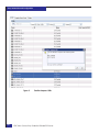
7. Repeat Step 1 through Step 4 for each HBA in the VMware ESX
Server system.
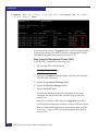
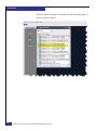
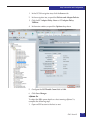
8. To verify that your host has been properly registered, right click
on the array and go to the Hosts tab.
The host will be reported as attached, but manually registered as
in the example of the system named l82bi199.lss.emc.com as
show in Figure 10 on page 49.
48
EMC Host Connectivity Guide for VMware ESX Server
Connectivity
Figure 10
Host reported as attached, but manually registered example
Fibre Channel
49
Connectivity
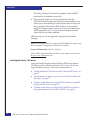
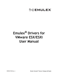
iSCSI
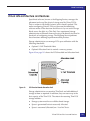
The Internet Small Computer Systems Interface (iSCSI) protocol
enables the transport of SCSI blocks through TCP/ IP network. iSCSI
works by encapsulating SCSI commands into TCP packets and
sending it over IP network. An example is shown in Figure 11.
Figure 11
SCSI commands encapsulated by Ethernet headers
iSCSI is IP-based traffic and therefore can be routed or switched using
standard (10 Mb/s, 100 Mb/s, 1 G, 10 G) Ethernet equipment.
Traditional Ethernet adapters (NICs) are designed to transfer
packetized file level data among PCs, servers, and storage devices,
such as NAS appliances.
In order for NIC to process block level data, the data needs to be
placed into a TCP/IP packet before being sent over the IP network.
This block level data packet creation and TCP/ IP processing is done
through the use of iSCSI drivers. The process, known as software (SW)
iSCSI, is extremely CPU intensive and lowers the overall server
performance. SW iSCSI does not support boot from SAN. For more
information on SW iSCSI, refer to “VMware ESX SW iSCSI” on
page 51.
The TCP/IP processing performance bottleneck has been the driving
force behind the development of TCP/IP offload engines (TOE) on
adapter cards. A TOE removes the TCP/IP processing from the host
CPU and completes TCP/IP processing and packet creation on the
HBA. Thus, a TCP/IP offload storage NIC operates more like a
storage HBA rather than a standard NIC. This is often referred to as
hardware (HW) iSCSI. HW iSCSI supports boot from SAN. For more
information on SW iSCSI, refer to “VMware ESX SW iSCSI” on
page 51.
50
EMC Host Connectivity Guide for VMware ESX Server
Connectivity
The setup of ESX server differs between SW and HW iSCSI. ESX
Server does not support both hardware and software initiators
running simultaneously.
Note: Refer to the EMC Support Matrix for supported HW iSCSI initiators.
Always ensure that the hardware iSCSI initiators are successfully
installed and recognized by the system.
VMware ESX SW iSCSI
This section describes the steps required to configure SW iSCSI
initiator ports.
Note: SW iSCSI does not support boot from SAN.
iSCSI traffic should be isolated from other network traffic.
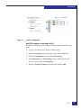
ESX 3.x SW iSCSI
support
Figure 12
◆
Supports only send targets discovery
◆
Requires both VMkernel port and service console to be on the
same vSwitch, as shown in Figure 12
VMkernel and service console on a single vSwitch
◆
Supports NIC-teaming
While configuring a software iSCSI initiator using NICs, VMware
recommends NIC-teaming to provide failover between multiple NICs,
which means the NICs are on the same vSwitch using the same IP
address.
ESX 4.x and ESXi 5.0
SW iSCSI support
◆
Supports both send and static targets discovery
◆
Requires only VMkernel port to be in the network configuration
◆
Supports multipathing
iSCSI
51
Connectivity
◆
Supports NIC-teaming
◆
Supports ALUA, failover mode 4 for VNX series and CLARiiON
system
◆
Supports EMC Powerpath/VE
Note: For more information about EMC PowerPath/VE, refer to
http://www.emc.com.
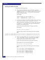
Setting up SW iSCSI
To set up the SW iSCSI initiator, complete the following steps.
Note: Some steps are optional, as noted, depending on the ESX version used.
Each step is outlined in more detail in this section:
1. “Set up VMkernel” on page 52
2. “Set up the service console (optional for ESX 4.x; not applicable
for ESXi 5.0)” on page 54
3. “Enable the SW iSCSI configuration” on page 55
4. “Add send targets” on page 55
5. “Add static targets (not applicable for ESX 3.5)” on page 55
Set up VMkernel
To set up the VMkernel, complete the following steps:
1. Log in to the VMware VI client as administrator.
2. From the inventory panel, select the server to be configured.
3. Click the Configuration tab and click Networking.
4. Click Add Networking.
5. In Connection Type, select VMkernel and click Next.
The Network Access page displays.
6. Either select an existing vSwitch or click Create a virtual switch.
Note: iSCSI traffic should be separated from other network traffic.
7. Check the box next to each adapter that you want to connect to
the vSwitch.
52
EMC Host Connectivity Guide for VMware ESX Server
Connectivity
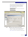
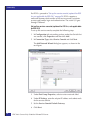
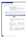
The VMkernel Connection Settings window displays. The
adapters that you select should appear in the Preview panel, as
shown in the next figure.
8. Click Next.
9. Under Port Group Properties, select or enter a network label.
10. Under IP Settings, enter the adapter IP address and subnet mask
for VMkernel.
11. Set the VMkernel Default Gateway. This must be a valid
address.
12. Click Next.
13. Review the Summary and if all of the settings are correct, click
Finish.
14. For ESX 4.x and ESXi 5.0 only, to verify SW iSCSI initiator
network has been correctly setup, open a console window by
issuing the following command:
# vmkping <target_ip_address>
You should be able to get response from the target.
iSCSI
53
Connectivity
For ESX 3.x, proceed to “Set up the service console (optional for ESX
4.x; not applicable for ESXi 5.0)” on page 54. ESX 3.x requires a
vmkiscsid daemon which resides in the service console) to initiates
sessions and handles login and authentication. The actual I/O goes
through VMkernel.
Set up the service console (optional for ESX 4.x; not applicable
for ESXi 5.0)
To set up the service console, complete the following steps:
1. In Configuration tab, networking section, under the vSwitch that
was created, click Properties and then click Add.
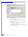
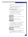
2. In Connection Type, select Service Console and click Next.
The Add Network Wizard dialog box appears, as shown in the
next figure.
3. Under Port Group Properties, select or enter a network label.
4. Under IP Settings, enter the adapter IP address and subnet mask
for the service console.
5. Set the Service Console Default Gateway.
6. Click Next.
54
EMC Host Connectivity Guide for VMware ESX Server
Connectivity
7. Review the Summary and if all of the settings are correct, click
Finish.
8. To verify SW iSCSI initiator network has been correctly set up,
open a console by issuing the following command:
# vmkping <target_ip_address>
You should be able to get response from the target.
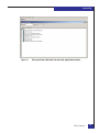
Enable the SW iSCSI configuration
1. Click the Configuration tab and then click Storage Adapters.
2. Select SW iSCSI adapter and then click Properties.
3. Under the General tab, click Configure.
4. Under Status, check the box next to Enabled.
5. If required, amend the iSCSI name and click OK.
Add send targets
Note: This steps is optional for ESX 4.x and ESXi 5.0, which may use Add
static targets.
Add target addresses for the hardware initiator.
Note: Both send and static targets discovery are supported.
To add send targets:
1. Click the Configuration tab and then click Storage Adapters.
2. Select SW iSCSI adapter and then click Properties.
3. Click the Dynamic Discovery tab and then click Add.
4. Enter the send targets server IP and click OK to add target
information from a selected storage system.
Add static targets (not applicable for ESX 3.5)
Note: ESX 4.x and ESXi 5.0 can use either Add Send targets or Add Static
Targets.
1. Click the Configuration tab and then click Storage Adapters.
2. Select SW iSCSI adapter and then click Properties.
3. Click the Static Discovery tab to add static targets and then click
Add.
iSCSI
55
Connectivity
4. Enter the send targets server IP, port, and iqn address and click
OK to add the static targets.
5. Click Close to close the iSCSI Initiator Properties page.
Once the iSCSI initiator ports on the ESX Server are configured, iSCSI
storage must be presented to the ESX Server. Refer to the latest EMC
Support Matrix for the most up-to-date information on which EMC
arrays that are supported via iSCSI attach to VMware ESX Server 3.x
and 4.x.
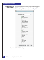
Enable services and agents in the initiator firewall
Configure the service console firewall to accept services and installed
management agents, enabling the services and agents to access the
ESX Server, by completing the following steps:
1. Log in to the VMware VI client as administrator.
2. In the VI Client, under Hosts and Clusters, click the server.
3. Click the Configuration tab and then click Security Profile.
4. Click Properties to open the Firewall Properties dialog box.
This dialog box lists services and management agents.
5. If not already checked, enable the software iSCSI Client by
checking the box.
6. Click OK.
Once the iSCSI initiator ports on the ESX Server are configured, iSCSI
storage must be presented to the ESX Server. Refer to the latest EMC
Support Matrix for the most up-to-date information on which EMC
arrays that are supported via iSCSI attach to VMware ESX Server 3.x.
Network configurations for ESX 4.x and ESXi 5.0
In a two or more NICs’ environment, SW iSCSI may be set up
through the use of a single vSwitch or dual vSwitch network
configuration, as shown in Figure 13 on page 57.
In ESX 4.x and ESXi 5.0, a single vSwitch containing two NICs can be
configured to use NIC teaming or port binding to provide failover
capabilities. Port binding can be enabled by overriding vSwitch
failover order such that each NIC is only bound to one VMkernel
port. Refer to “Set up 1:1 VMkernel to network adapters mapping”
on page 61 for steps to perform port binding.
56
EMC Host Connectivity Guide for VMware ESX Server
Connectivity
Note: EMC recommends having the two NICs/ VMkernel ports are on
different subnets. Ensure the SP ports belonging to the same Storage
Processor are also on different subnets.
Figure 13
Two NICs on a single vSwitch iSCSI configuration
iSCSI
57
Connectivity
Likewise, two vSwitches can be created on ESX 4.x and ESXi 5.0 and
each vSwitch can be bound to one or more NICs, as shown in
Figure 14.
Figure 14
Two NICs in dual vSwitch iSCSI configuration
Setting up multipathing with all iSCSI adapters on a single vSwitch for ESX 4.x and ESXi 5.0
To set up multipathing with all iSCSI adapters on a single vSwitch for
the ESX 4.x and ESXi 5.0, the following steps must be completed.
Each step is outlined in more detail in this section:
1. “Add iSCSI adapters to existing vSwitch” on page 59
2. “Set up 1:1 VMkernel to network adapters mapping” on page 61
Figure 15 on page 59 shows an example of a vSwitch configuration.
58
EMC Host Connectivity Guide for VMware ESX Server
Connectivity
Figure 15
vSwitch configuration
Add iSCSI adapters to existing vSwitch
To add iSCSI adapters to an existing vSwitch, complete the following
steps:
1. Log in to the VMware VI client as administrator.
2. From the inventory panel, select the server to be configured.
3. Click the Configuration tab and click Networking.
4. In Configuration tab, Networking section, under the vSwitch
that was just created, click Properties.
5. Select the Network Adapters tab and then click the Add.
iSCSI
59
Connectivity
The Adapter Selection window displays, as shown in the next
figure.
6. Check the box next to each adapter that you want to connect to
the vSwitch and click Next.
7. Click Next.
8. Review the Summary and if all of the settings are correct, click
Finish.
60
EMC Host Connectivity Guide for VMware ESX Server
Connectivity
Set up 1:1 VMkernel to network adapters mapping
To set up 1:1 VMkernel to network adapters mapping, complete the
following steps:
1. In the vSwitch Properties window, shown in the next figure,
select the VMkernel and click Edit.
iSCSI
61
Connectivity
2. Select the NIC Teaming tab and check the box Override vSwitch
failover order:, as shown in the next figure.
3. Set one active adapter for each VMkernel and move the rest of the
adapters to Unused Adapters.
Repeat this step for every VMkernel on the vSwitch.
Note: There should be the same number of VMkernel and Network
adapters.
62
EMC Host Connectivity Guide for VMware ESX Server
Connectivity
4. Activate host-based multipathing by connecting each VMkernel
ports e.g., vmk0 and vmk1, to the iSCSI initiator from the service
console by issuing the following commands:
• For vSphere 4:
# esxcli swiscsi nic add -n vmk0 -d vmhba32
# esxcli swiscsi nic add -n vmk1 -d vmhba32
# esxcli swiscsi nic list -d vmhba32
• For vSphere 5:
# esxcli iscsi networkportal add -n vmk0 -A vmhba32
# esxcli iscsi networkportal add -n vmk1 -A vmhba32
# esxcli iscsi networkportal list -A vmhba32
Both vmk0 and vmk1 should be listed and there should be two
separate paths to the same target.
5. To remove VMkernel ports from iSCSI initiators, ensure there are
no active session between hosts and targets, and run the
following command from service console:
• For vSphere 4:
# esxcli swiscsi nic remove -n vmk0 -d vmhba32
• For vSphere 5:
# esxcli iscsi networkportal remove -n vmk0 -A vmhba32
VMware ESX HW iSCSI
This section contains information on the VMware ESX HW iSCSI.
ESX 3.X HW iSCSI
support
ESX 4.x and ESXi 5.0
HW iSCSI support
Supports both send and static targets discovery
◆
Supports both send and static targets discovery
◆
Supports ALUA mode, failover mode 4 for VNX series and
CLARiiON systems
◆
Supports EMC PowerPath/VE
Note: For more information about EMC PowerPath/VE, refer to
http://www.emc.com.
Configuring HW iSCSI
initiator
To configure ESX/ESXi hardware initiator (iSCSI HBA), complete the
following steps:
iSCSI
63
Connectivity
1. Log in to the VMware VI/vSphere client as administrator.
2. From the inventory panel, select the server to be configured.
3. Click the Configuration tab, and click Storage Adapters.
4. Select HW iSCSI initiator to configure, and click Properties.
5. In the HW iSCSI Initiator Properties page, click the General tab
and then click Configure.
6. Under iSCSI Properties, can enter an iSCSI name and iSCSI
Alias for the hardware initiator and then click OK.
7. Under Hardware Initiator Properties, add IP settings for the
initiator.
8. Add target addresses for hardware initiator, both send and static
targets discovery are supported:
a. Click the Dynamic Discovery tab, to add send targets, and
then click Add.
b. Enter the send targets server IP and click OK to add target
information from a selected storage system.
Or
a. Click the Static Discovery tab, to add static targets, and then
click Add.
b. Enter the send targets server IP, port, and iqn address and
click OK to add
9. Click Close to close the iSCSI Initiator Properties page.
Once the iSCSI initiator ports on the ESX Server are configured, iSCSI
storage must be presented to the ESX Server. Please refer to the latest
EMC Support Matrix for EMC arrays that are currently supported
through iSCSI attach to VMware ESX Server 3.x and 4.x.
VMAX or Symmetrix connectivity
The following bit settings are required on the director ports for
ESX/ESXi operations:
64
◆
Common serial number (C)
◆
SCSI 3 (SC3) set (enabled)
◆
Unique world wide name (UWN)
EMC Host Connectivity Guide for VMware ESX Server
Connectivity
◆
SPC-2 (Decal) (SPC2) SPC-2 flag is required
The bit settings can be configured using EMC Symmetrix
Management Console or Solutions Enabler. Refer to “VMAX and
Symmetrix array configurations” on page 94 for more details.
This section details the steps needed for:
◆
“Using Solution Enabler” on page 65
◆
“Using Symmetrix Management Console (SMC)” on page 66
Using Solution Enabler
To use Solution Enabler, complete the following steps:
1. Install Solution Enabler for ESX host.
Note: A license is required.
2. Go to the default location:
cd /opt/emc/SYMCLI/V6.5.1/bin
3. Run #./symcfg discover.
4. Subsequently, run #./symcfg list.
5. Ensure the attached VMAX or Symmetrix have a local
attachment.
6. Verify the ESX host is visible to the array by issuing the following
command:
iSCSI
65
Connectivity
#./symmask -sid <last 3 digits of the symm frame> list logins -dir <dir number>
-p <port number> | more
A initiator will be shown as Logged In after a LUN has been masked
to the initiator. Refer to the EMC Symmetrix Management Console
Online Help for information on how to mask a LUN.
Using Symmetrix Management Console (SMC)
To use the SMC, complete the following steps:
1. Log in to the SMC from a browser.
Note: Disable pop-up blockers.
2. Expand the Symmetrix Arrays folder on the left panel and then
select the array connected.
3. Expand the Symmetrix Masking folder.
4. Expand the Host Bus Adapters folder.
5. Expand the iSCSI folder.
The initiator should be listed with a record for every target
connected. Ensure that the HBA and Port Flags in effect are
correctly set.
Similarly, an initiator will be shown as Logged In only after a
LUN has been masked to the initiator, as shown in the next figure.
Refer to Symmetrix Management Console online help available
on on http://support.EMC.com for information about how to
mask a LUN.
66
EMC Host Connectivity Guide for VMware ESX Server
Connectivity
VNX series and CLARiiON connectivity
For a failover-enabled environment, the required settings are as
follows:
◆
Initiator Type: CLARiiON Open
◆
ArrayCommPath: Enabled
◆
FailOverMode: 1
◆
Unit Serial Number: Array
Note: The failover functionality referred to here is the native failover
functionality incorporated into the VMkernel.
In order to manually register the host, you must first identify the iqns
of the initiators. iSCSI name and iqn refers to the same thing. The iqn
iSCSI
67
Connectivity
is used when registering the VMware ESX Server host onto the VNX
series and CLARiiON systems. The iqn can be found from VI/
VSphere client Inventory panel > Configuration tab, Storage
adapters.
To manually add VMware ESX host to VNX series and CLARiiON,
complete the following steps:
1. Log in to the management interface from a browser.
Note: Java is required.
2. Select the Storage tab, right-click on the appropriate array, and
select the Connectivity Status option, as shown in the next figure.
3. Select the initiator iqn from the list, in the Connectivity Status
dialog box.
4. Click Register, or click New if the initiator record cannot be
found.
The Create Initiator Record dialog box displays when New is
clicked, as shown in the next figure.
68
EMC Host Connectivity Guide for VMware ESX Server
Connectivity
A similar dialog box appears when Register is clicked, except the
name the dialog box is Register Initiator Record.
5. Update the Host information:
a. Set Initiator Type to CLARiiON Open.
b. Set the Failover Mode: to1.
c. Check the ArrayCommPath box.
d. Select the target SP - port to connect to.
6. Click OK to update the host information.
7. Repeat Step 3 through Step 6 for the every other initiator listed for
the VMware ESX host.
8. To verify the host has been correctly registered, select the Host tab
in the Enterprise Storage window.
iSCSI
69
Connectivity
The host will be reported as attached, but manually registered, as
shown in the next figure.
70
EMC Host Connectivity Guide for VMware ESX Server
Connectivity
FCoE initiator configurations
This section provides information on configuring the Emulex,
QLogic, Brocade, and Cisco FCoE converged network adapters
(CNAs) with the VMware ESX Server. FCoE adapters represent a
method to converge both Fibre Channel and Ethernet traffic over a
single physical link to a switch infrastructure that manages both
storage (SAN) and network (IP) connectivity within a single unit.
This section contains the following information:
◆
“Configuring Emulex FCoE CNAs with VMware ESX Server” on
page 71
◆
“Configuring QLogic FCoE CNAs with VMware ESX Server” on
page 80
◆
“Configuring Brocade FCoE CNAs with VMware ESX Server” on
page 85
◆
“Cisco Unified Computing System with FCoE” on page 90
◆
“Configuring FCoE for Intel Ethernet Server Adapter with
VMware ESX server” on page 92
Configuring Emulex FCoE CNAs with VMware ESX Server
This section provides information on configuring Emulex FCoE
CNAs with the VMware ESX Server, including:
◆
“Installing the CNA” on page 71
◆
“Updating the Emulex CNA firmware and boot BIOS” on page 72
◆
“Updating the Emulex CEE/Menlo firmware” on page 75
◆
“Installing the Emulex CNA driver” on page 76
Installing the CNA
To install the CNA:
1. Install VMware ESX Server 3.5 update 2 or later on your server.
For instructions on installing the operating system, refer to the
relevant documentatioin at
http://www.VMware.com/support/pubs.
2. Power off the host system.
FCoE initiator configurations
71
Connectivity
3. With the host system powered off, install the CNA and make the
necessary cable connections as instructed in the accompanying
CNA documentation (or on the Emulex website at
www.emulex.com).
The card installs into a single PCI bus slot.
4. Reapply power and allow the system to boot normally.
Updating the Emulex CNA firmware and boot BIOS
Using HBAnywhere
To update the Emulex CNA firmware and boot BIOS for LightPulse
adapters, use HBAnywhere, using the following steps:
1. If you do not already have the Emulex HBAnyware Applications
kit installed on the ESX Server, download the latest available
Emulex HBAnyware Applications kit that is compatible with the
ESX Server version that you are running from www.emulex.com.
2. Install the HBAnyware CLI on the ESX Server:
a. Log in as ‘root’ at the ESX Server console or in a secure shell
session to the ESX Server.
b. Copy the elxVMwarecorekit <kit version>.rpm file to a
directory on the install machine.
c. Using the cd command, change to the directory where you
copied the rpmfile.
d. Install the rpm. Type: rpm -i elxVMwarecorekit <kit
version>.rpm
– The rpm contents are installed in /usr/sbin/hbanyware.
– The hbacmd utility is also located in this directory.
3. Copy the appropriate firmware and BIOS files from the CD-ROM
or the Emulex website to the appropriate directory,
/usr/sbin/hbanyware:
• The firmware file for Emulex LP21000 CNA is ad100a5.all
• The firmware file for Emulex LP21002 CNA is af100a5.all
• The BIOS file for Emulex LP2100x CNA is AB202A2.PRG
4. Execute the command /usr/sbin/hbanyware/hbacmd ListHBAs
and record the port WWN information for all adapters within the
host.
5. To update the Emulex CNA firmware:
72
EMC Host Connectivity Guide for VMware ESX Server
Connectivity
a. Execute the command /usr/sbin/hbanyware/hbacmd
Download <WWPN> <firmwarefile>, where WWPN is the first
Port WWN recorded from Step 4, and firmwarefile is the
firmware file name listed in Step 3.
The utility will report "Download Complete" when the
firmware download has completed successfully.
b. Repeat Step 5a for each adapter port WWN reported in Step 4
to ensure that all adapter instances within the host have been
updated.
6. To update the Emulex CNA Boot BIOS:
a. Execute the command /usr/sbin/hbanyware/hbacmd
Download <WWPN> <BIOSfile>, where WWPN is the first
Port WWN recorded from Step 4, and BIOSfile is the BIOS file
name listed in Step 3.
The utility will report "Download Complete" when the BIOS
download has completed successfully.
b. If the installed adapter is a dual-ported model, then the boot
BIOS does not need to be downloaded to each adapter port;
downloading it to either port results in both ports being
updated with the latest BIOS. Otherwise, for multiple
single-port adapter models, repeat Step 6a for each adapter
port WWN reported in Step 4, to ensure that all adapter
instances within the host have been updated.
Using OneCommand Manager
To update the Emulex CNA firmware and boot BIOS for OneConnect
adapters, use OneCommand Manager:
◆
If you do not already have the Emulex One Command Manager
Application kit installed on the ESX Server, download the latest
available Emulex OneCommand Manager Application kit that is
compatible with the ESX Server version that you are running
from www.emulex.com.
◆
To install the OneCommand Manager application CLI on a new
system, install the specific rpm file for the driver for your
VMware version.
Prerequisites
OneCommand Manager requires the LPFC driver version 7.4 or later
to be loaded. Installing the driver is described in the next section.
FCoE initiator configurations
73
Connectivity
Note the following:
◆
In-band management (FC based management) is not supported
on VMware ESX 3.5 servers. Use out-of band management
(TCP/IP based management) to remotely manage adapters on
ESX 3.5 servers. For VMware ESX 3.5 servers, the firewall on the
ESX Server must be opened to manage systems remotely using
TCP/IP-based management. To enable TCP port #23333, run the
following commands:
esxcfg-firewall --openPort 23333,tcp,in,OneCommand
esxcfg-firewall -openPort 23333,tcp,out,OneCommand
◆
To verify that the correct port is open, run the following
command:
esxcfg-firewall -q
◆
The TCP port number can be changed. If it is not changed, the
default is 23333. Refer to the VMware Server Configuration Guide,
available on http://support.EMC.com, for more details on how
to configure the ESX firewall.
To install the OneCommand Manager application CLI, complete the
followiing steps:
1. Log in to the ESX Server Host COS.
2. Copy the elxocmcore-esxNN-<kit version>.<arch>.rpm file to a
directory on the install machine.
3. Go to the directory where the rpm file is located and install it.
Type:
rpm -U elxocmcore-esxNN-<kit version>.<arch>.rpm
where NN is 35 for an ESX 3.5 system. The rpm contents are
installed in /usr/sbin/hbanyware. The OneCommand Manager
application CLI is also located in this directory.
To upgrade the firmware and Boot bios, complete the following steps:
1. The firmware zip file must be downloaded from the Emulex
website. The file must be unzipped and extracted to a folder on a
local drive.
• The firmware and boot code for OCe10102-FM-E and
OCe10102-FX-E CNA is S2200017.ufi.
• The firmware and boot code for OCe10102-IX-E and
OCe10102-IM-E CNA is S1374004.ufi.
74
EMC Host Connectivity Guide for VMware ESX Server
Connectivity
2. If the adapter is already connected to a boot device, the system
must be in a state in which this type of maintenance can be
performed:
• I/O activity on the bus has been stopped.
• Cluster software, or any other software that relies on the
adapter to be available, is stopped or paused.
It is recommended that you put the host in maintenance mode
before performing firmware upgrade.
3. Run the following command:
hbacmd Download <WWPN|MAC> <FileName>
where
– WWPN is the World Wide Port Name of the adapter to
which you want to load firmware.
– MAC is the MAC address of the NIC or iSCSI port to which
you want to load firmware.
– FileName is the File name of the firmware image to load
(this is the filename specified in Step 1.
Updating the Emulex CEE/Menlo firmware
FCoE adapters include an additional chip component that requires
the latest supported firmware. This chip is commonly referred to as a
CEE (converged enhanced ethernet), or Menlo chip, the purpose of
which is to handle the convergence of storage (FC) and network (IP)
traffic over a single ethernet interface.
To update the CEE/Menlo firmware on the CNAs
1. Copy the appropriate CEE/Menlo firmware file from the
CD-ROM or the EMC-approved section of the Emulex website to
the appropriate directory, /usr/sbin/hbanyware.
The CEE firmware file for Emulex LP2100x CNA is cee-0.5a5.bin.
2. Execute the command /usr/sbin/hbanyware/hbacmd ListHBA
and record the Port WWN information for all adapters within the
host.
3. Execute the command /usr/sbin/hbanyware/hbacmd
CEEdownload <WWPN> <Filename>, where WWPN is the first
Port WWN recorded from Step 2, and Filename is the firmware file
name listed in Step 1.
FCoE initiator configurations
75
Connectivity
The utility will report "Download Complete" when the BIOS
download has completed successfully.
4. If the installed adapter is a dual-ported model, then the
CEE/Menlo firmware does not need to be downloaded to each
adapter port; downloading it to either port results in both ports
being updated with the latest BIOS. Otherwise, for multiple
single-port adapter models, repeat Step 3 for each adapter port
WWN reported in Step 2, to ensure that all adapter instances
within the host have been updated.
CEE firmware can also be upgraded using the OneCommand
Manager.
Note: The following command is supported for LP21000 series adapters only.
This command is not supported for OneConnect adapters.
hbacmd CEEDownload <WWPN> <Filename>
where WWPN is the World Wide Port Name of the adapter and Filename is
the ame of the CEE firmware file.
Installing the Emulex CNA driver
Using the Emulex adapter with the VMware ESX Server requires
CNA driver software. Refer to the latest EMC Support Matrix for
supported driver versions. This section explains how to:
76
◆
“Install the Emulex CNA driver on the VMware ESX Server” on
page 77
◆
“Install drivers for devices as part of a new ESX installation (for
ESX only)” on page 77
◆
“Update or add drivers on existing ESX installations using ESX
update (for ESX only)” on page 78
◆
“Update or add drivers on existing ESX and ESXi installations
using vihostupdate (for both ESX and ESXi)” on page 79
EMC Host Connectivity Guide for VMware ESX Server
Connectivity
Install the Emulex CNA driver on the VMware ESX Server
To install the Emulex CNA driver on the VMware ESX Server:
1. Download the driver RPM package from
http://www.emulex.com. If the driver is an rpm package,
complete the following instructions.
Note: Currently, the Emulex driver included in the VMware ESX Server
3.5 update 2 does not support Emulex FCoE CNAs. Before installing the
CNA driver downloaded in Step 1, the existing Emulex driver must be
uninstalled, as explained in Step 2.
2. Uninstall the existing Emulex driver by completing the following
steps:
a. Execute the command rpm -qa | grep lpfc and record the
name of the existing driver package.
b. Execute the command rpm -e <existing_driver> where
existing_driver is the existing driver package fromStep a.
c. Reboot the server.
3. Install the Emulex FCoE CNA driver that was downloaded in
Step 1:
a. Execute the command rpm -Uvh --force <New driver RPM>
where New driver RPM is the driver package downloaded in
Step 1.
b. Reboot the server.
Following the installation of the proper driver for the FCoE adapter,
the Fibre Channel interface will function identically to that of a
standard Emulex Fibre Channel HBA, as the LP21000/LP21002
simply encapsulates Fibre Channel traffic within ethernet frames.
Install drivers for devices as part of a new ESX installation (for
ESX only)
Note: This procedure has changed since the 3.5 version of driver CD. In ESX
3.5, the driver CD can be used as the boot CD. For ESX 4.0 and later, you will
need the ESX installation DVD to begin.
For ESX v3.5:
Use this CD as a boot CD only when the new driver must enable the
target device on which ESX will be installed. This procedure can only
be used with ESX 3.x.
FCoE initiator configurations
77
Connectivity
1. Place the driver CD in the CD-ROM drive of the host machine.
2. Start the host machine.
3. When prompted for an upgrade or installation, press Enter for
graphical mode.
4. Choose the language you prefer.
5. Select a keyboard type.
6. After you are prompted to swap the driver CD with the ESX 3.5
installation CD, insert the ESX 3.5 installation CD and continue
with ESX installation.
For ESX v4.x:
1. Place the ESX Installation CD in the CD-ROM drive of the host
machine.
2. Start the host machine.
3. Accept the terms of the license agreement.
4. Select a keyboard type.
5. When prompted for Custom Drivers, select Yes to install custom
drivers.
6. The installer prompts you to insert the media containing the
custom drivers.
After you add the custom drivers to the list, the installer prompts
you to reinsert the ESX installation DVD and continue with the
installation.
Update or add drivers on existing ESX installations using ESX
update (for ESX only)
To update or add drivers on existing ESX installations using ESX
update:
1. Power on the ESX host and log into an account with
administrator capability.
2. Place the driver CD in the CD-ROM drive of the ESX host.
3. Mount the driver CD.
4. Navigate to <cd mount point>/offline-bundle/ and locate the
<offline-bundle>.zip file.
78
EMC Host Connectivity Guide for VMware ESX Server
Connectivity
5. Run the esxupdate command to install drivers using the offline
bundle:
esxupdate --bundle=<offline-bundle>.zip update
Update or add drivers on existing ESX and ESXi installations
using vihostupdate (for both ESX and ESXi)
Prerequisite
Before you can update or patch an ESX/ESXi host from the command
line, you must have access to a machine on which you can run the
VMware vSphere Command Line Interface (vSphere CLI). You can
install the vSphere CLI on your Microsoft Windows or Linux system
or import the VMware vSphere Management Assistant (vMA) virtual
appliance onto your ESX/ESXi host.
To update or add drivers on existing ESX and ESXi installations using
the vihostupdate command:
1. Power on the ESX or ESXi host.
2. Place the driver CD in the CD-ROM drive of the host where either
the vSphere CLI package is installed or vMA is hosted.
3. Mount the driver CD.
4. Navigate to <cd mount point>/offline-bundle/ and locate the
<offline-bundle>.zip file.
5. Run the vihostupdate command to install drivers using the
offline bundle:
vihostupdate --server <test.machine.address>--install --bundle
<offline-bundle>.zip
For more details on the vihostupdate command, see the vSphere
Command-Line Interface Installation and Reference Guide located at
http://www.VMware.com.
For ESX 3.5 U2 and later, see the Remote Command-Line Interface
Installation and Reference Guide located at http://www.VMware.com.
Verify that the driver is installed successfully:
1. Run the esxupdate query command.
A message containing the information about the driver appears.
2. View the PCI ID XML file in the /etc/VMware/pciid/ directory.
The driver information is available in the file.
FCoE initiator configurations
79
Connectivity
3. Check for the latest version of the driver module in the following
directory:
/usr/lib/VMware/vmkmod/
4. Enter vmkload_mod -l command to verify that the driver is
loaded and functioning.
The driver is listed in the displayed list.
Configuring QLogic FCoE CNAs with VMware ESX Server
This section provides information on configuring QLogic FCoE
CNAs with the VMware ESX Server, including:
◆
“Installing the CNA” on page 80
◆
“Updating the QLogic CNA boot BIOS” on page 80
◆
“Updating the QLogic CEE/Menlo firmware” on page 82
◆
“Installing the QLogic CNA driver” on page 82
Installing the CNA
To install the CNA:
1. Install VMware ESX Server 3.5 update 2 or later on your server.
For instructions on installing the operating system, refer to the
relevant documentation at http://www.VMware.com.
2. Power off the host system.
3. With the host system powered off, install the CNA and make the
necessary cable connections as instructed in the accompanying
CNA documentation (or on the QLogic website at
www.QLogic.com.
The card installs into a single PCI bus slot.
4. Reapply power and allow the system to boot normally.
Updating the QLogic CNA boot BIOS
To update the QLogic CNA boot BIOS:
1. If you do not already have the QLogic SANsurfer FC HBA CLI
package installed on the ESX Server, download the latest
available version compatible with the ESX Server version that
you are running from www.QLogic.com.
80
EMC Host Connectivity Guide for VMware ESX Server
Connectivity
Note: If the ESX Server has a
/opt/QLogic_Corporation/SANsurferCLI/ directory, the QLogic
SANsurfer FC HBA CLI package is already installed.
2. To install the HBAnyware CLI on the ESX Server:
a. Log in as ‘root’ at the ESX Server console or in a secure shell
session to the ESX Server.
b. Copy the scli-<kit version>.rpm.gz file to a directory on the
install machine.
c. Using the cd command, change to the directory where you
copied the rpm.gz file.
d. Unzip the file. Type: gunzip scli-<kit version>.rpm.gz
e. Install the rpm. Type: rpm -i scli-<kit version>.rpm
– The rpm contents are installed in
/opt/QLogic_Corporation/SANsurferCLI/.
– The scli utility is also located in this directory.
3. Copy the appropriate BIOS file from the CD-ROM or the QLogic
website to the ESX Server. The BIOS file for QLogic QLE8042
CNA is: Q84AF100.bin.
The Boot Code file for QLogic QLE8142 and QLE8152 is
Q8Q10198.bin. This file is the combined binary file which
includes the binaries for the firmware, PXE, FCode, UEFI, and
BIOS.
4. Execute the command
/opt/QLogic_Corporation/SANsurferCLI/scli
and then select options 7 (Utilities), then 1 (Flash update), then 1
(FCoE Engine), and then 1 (Update Entire Image).
5. The utility prompts to enter a file name.
Enter the name of the BIOS file listed in Step 3. The utility should
report the update has completed successfully.
6. Press Enter to continue, then select options 0 (Return to Main
Menu) then 12 to exit the SANsurferCLI utility.
FCoE initiator configurations
81
Connectivity
Updating the QLogic CEE/Menlo firmware
FCoE adapters include an additional chip component that requires
the latest supported firmware. This chip is commonly referred to as a
(converged enhanced ethernet), or Menlo chip, the purpose of which
is to handle the convergence of storage (FC) and network (IP) traffic
over a single ethernet interface.
To update the CEE/Menlo firmware on the CNAs:
1. Copy the appropriate CEE/Menlo firmware file from the
CD-ROM or the EMC-approved section of the QLogic website to
the appropriate directory,
/opt/QLogic_Corporation/SANsurferCLI.
The CEE firmware file for QLogic QLE8042 CNA is
mlo_fw_v1_2_0.bin.
2. Using the SANsurfer Command Line Interface (CLI) From the
CLI menu select:
10: Utilities
When you select FCoE Utility from the Utilities menu, SANsurfer
FC HBA CLI prompts you to select an FCoE Engine, and then
provides the following menu for that engine:
FCoE Utilities Menu
FCoE Engine (QLE8042)
Desc: QLE8042 Mercury CNA
1: Update Firmware
2: Stats
3: Logs
4: Return to Previous Menu
3. To update FCoE Engine firmware, select option 1 from the
Utilities menu:
10: Utilities >n: FCoE Utility >1:
4. To update firmware using the command line option, enter the
following command:
scli -fcoe (<hba instance> | <hba wwpn>) --loadfw <firmware file>
Installing the QLogic CNA driver
Using the QLogic adapter with the VMware ESX Server requires
CNA driver software. Refer to the latest EMC Support Matrix for
supported driver versions.
82
EMC Host Connectivity Guide for VMware ESX Server
Connectivity
To install the QLogic CNA driver on the VMware ESX Server:
Download the driver RPM package from http://www.QLogic.com.
Following the installation of the proper driver for the FCoE adapter,
the Fibre Channel interface will function identically to that of a
standard QLogic Fibre Channel HBA, as the QLE8042 simply
encapsulates Fibre Channel traffic within ethernet frames.
If the driver package is an iso file, burn the iso file into a CD. You can
use the driver CD in several ways, each further discussed in this
section:
◆
“Install drivers for devices as part of a new ESX installation (for
ESX only)” on page 83
◆
“Update or add drivers on existing ESX installations using
esxupdate (for ESX only)” on page 84
◆
“Update or add drivers on existing ESX and ESXi installations
using vihostupdate (for both ESX and ESXi)” on page 84
Install drivers for devices as part of a new ESX installation (for
ESX only)
Note: This procedure has changed since the 3.5 version of driver CD. In ESX
3.5, the driver CD can be used as the boot CD. For ESX 4.0 and later, you will
need the ESX installation DVD to begin.
For ESX v3.5:
Use this CD as a boot CD only when the new driver must enable the
target device on which ESX will be installed. This procedure can only
be used with ESX 3.x.
1. Place the driver CD in the CD-ROM drive of the host machine.
2. Start the host machine.
3. When prompted for an upgrade or installation, press Enter for
graphical mode.
4. Choose the language you prefer.
5. Select a keyboard type.
6. After you are prompted to swap the driver CD with the ESX 3.5
installation CD, insert the ESX 3.5 installation CD and continue
with ESX installation.
FCoE initiator configurations
83
Connectivity
For ESX v4.x:
1. Place the ESX Installation CD in the CD-ROM drive of the host
machine.
2. Start the host machine.
3. Accept the terms of the license agreement.
4. Select a keyboard type.
5. When prompted for Custom Drivers, select Yes to install custom
drivers.
6. The installer prompts you to insert the media containing the
custom drivers.
After you add the custom drivers to the list, the installer prompts
you to reinsert the ESX installation DVD and continue with the
installation.
Update or add drivers on existing ESX installations using
esxupdate (for ESX only)
1. Power on the ESX host and log into an account with
administrator capability.
2. Place the driver CD in the CD-ROM drive of the ESX host.
3. Mount the driver CD.
4. Navigate to <cd mount point>/offline-bundle/ and locate the
<offline-bundle>.zip file.
5. Run the esxupdate command to install drivers using the offline
bundle:
esxupdate --bundle=<offline-bundle>.zip update
Update or add drivers on existing ESX and ESXi installations
using vihostupdate (for both ESX and ESXi)
Prerequisite
Before you can update or patch an ESX/ESXi host from the command
line, you must have access to a machine on which you can run the
VMware vSphere Command Line Interface (vSphere CLI). You can
install the vSphere CLI on your Microsoft Windows or Linux system
or import the VMware vSphere Management Assistant (vMA) virtual
appliance onto your ESX/ESXi host.
To update or add drivers on existing ESX and ESXi installations using
the vihostupdate command:
84
EMC Host Connectivity Guide for VMware ESX Server
Connectivity
1. Power on the ESX or ESXi host.
2. Place the driver CD in the CD-ROM drive of the host where either
the vSphere CLI package is installed or vMA is hosted.
3. Mount the driver CD.
4. Navigate to <cd mount point>/offline-bundle/ and locate the
<offline-bundle>.zip file.
5. Run the vihostupdate command to install drivers using the
offline bundle:
vihostupdate --server <test.machine.address>--install --bundle
<offline-bundle>.zip
For more details on the vihostupdate command, see the vSphere
Command-Line Interface Installation and Reference Guide located at
http://www.VMware.com.
For ESX 3.5 U2 and later, see the Remote Command-Line Interface
Installation and Reference Guide located at http://www.VMware.com.
Configuring Brocade FCoE CNAs with VMware ESX Server
This section provides information on configuring Brocade FCoE
CNAs with the VMware ESX Server, including:
◆
“Installing the CNA” on page 85
◆
“Installing the Brocade 2.0 CNA driver” on page 86
◆
“Updating the Brocade CNA firmware and boot BIOS” on
page 89
Installing the CNA
To install the CNA:
1. Install VMware ESX Server 3.5 update 2 or later on your server.
For instructions on installing the operating system, refer to the
relevant documentation at http://www.VMware.com.
2. Power off the host system.
3. With the host system powered off, install the CNA and make the
necessary cable connections as instructed in the accompanying
CNA documentation. The card installs into a single PCI-e slot.
4. Reapply power and allow the system to boot normally.
FCoE initiator configurations
85
Connectivity
Installing the Brocade 2.0 CNA driver
Using the Brocade adapter with the VMware ESX/ESXi Server
requires CNA driver software. Refer to the latest EMC Support Matrix
for supported driver versions.
If the downloaded driver file is an iso image, burn the iso image into
a CD. You can use the driver CD in several ways:
ESX 4.x Server
◆
“Install drivers for devices as part of a new ESX installation (for
ESX only)” on page 87
◆
“Update existing driver or install new drivers for an existing ESX
installations using esxupdate (for ESX only)” on page 88
◆
“Update existing driver or install new drivers for an existing ESX
and ESXi installations using vihostupdate (for both ESX and
ESXi)” on page 88
To install the Brocade CNA driver on the VMware ESX Server:
1. Download the appropriate CNA driver package from the "10
Gbps ETHERNET TO PCIe CNAs” section on
http://www.brocade.com/hba.
2. Install the driver by following instructions under the "Driver
Packages" section on the driver download page.
3. Configure the firewall as detailed in the Brocade Adapters
Installation and Reference Manual, available at
http://www.brocade.com.
4. Copy the driver package to a temporary directory.
5. Extract the file using the following command:
tar –zxvf brocade_driver_esx35_<version>.tar.gz
6. Run the installer with the following command:
./brocade_install.sh
7. Reboot the system.
8. Confirm the driver package was installed using the following
command:
vmkload_mod –l
An entry for bfa will exist for the storage driver and bna for the
network driver.
86
EMC Host Connectivity Guide for VMware ESX Server
Connectivity
ESXi 5 Server
To install the Brocade CNA driver on the VMware ESXi Server:
1. Place host in maintenance mode.
2. Copy the Brocade driver package to the vMA and untar it.
3. Run the install script
# ./brocade_install_esxi.sh
4. After the host updates successfully, exit from maintenance mode.
5. Using the vSphere Client, right-click ESXi and choose the Exit
Maintenance Mode option.
6. Reboot the ESXi server.
7. After ESXi server reboot is complete, run the following command
to make sure the drivers are installed.
# vmkload_mod -l
The Brocade drivers should now display in the list.
Install drivers for devices as part of a new ESX installation (for
ESX only)
Note: This procedure has changed since the 3.5 version of driver CD. In ESX
3.5, the driver CD can be used as the boot CD. For ESX 4.0 and later, you will
need the ESX installation DVD to begin.
For ESX v3.5:
Use this CD as a boot CD only when the new driver must enable the
target device on which ESX will be installed. This procedure can only
be used with ESX 3.x.
1. Place the driver CD in the CD-ROM drive of the host machine.
2. Start the host machine.
3. When prompted for an upgrade or installation, press Enter for
graphical mode.
4. Choose the language you prefer.
5. Select a keyboard type.
6. After you are prompted to swap the driver CD with the ESX 3.5
installation CD, insert the ESX 3.5 installation CD and continue
with ESX installation.
FCoE initiator configurations
87
Connectivity
For ESX v4.x:
1. Place the ESX Installation CD in the CD-ROM drive of the host
machine.
2. Start the host machine.
3. Accept the terms of the license agreement.
4. Select a keyboard type.
5. When prompted for Custom Drivers, select Yes to install custom
drivers.
6. The installer prompts you to insert the media containing the
custom drivers.
After you add the custom drivers to the list, the installer prompts
you to reinsert the ESX installation DVD and continue with the
installation.
Update existing driver or install new drivers for an existing ESX
installations using esxupdate (for ESX only)
1. Copy the bfa*.iso to some location, such as /root/bfa/bfa*.iso.
2. Create a temporary directory under /tmp eg: /tmp/bfa.
3. Mount the bfa*.iso file on the esx server, such as
mount -t iso9660 -o loop /root/bfa/bfa*.iso /tmp/bfa
4. Run the following command:
/usr/sbin/esxupdate --bundle =
/tmp/bfa/offline-bundle/bfa*.zip --maintenancemode update
5. Verify that the bfa modules shows up under
/usr/lib/VMware/vmkmod directory
6. Reboot the system
7. Verify if the driver is loaded using the vmkload_mod -l
command.
Update existing driver or install new drivers for an existing ESX
and ESXi installations using vihostupdate (for both ESX and ESXi)
Prerequisite
Before you can update or patch an ESX/ESXi host from the command
line, you must have access to a machine on which you can run the
VMware vSphere Command Line Interface (vSphere CLI). You can
install the vSphere CLI on your Microsoft Windows or Linux system
88
EMC Host Connectivity Guide for VMware ESX Server
Connectivity
or import the VMware vSphere Management Assistant (vMA) virtual
appliance onto your ESX/ESXi host.
To update or add drivers on existing ESX and ESXi installations using
the vihostupdate command:
1. Power on the ESX or ESXi host.
2. Place the driver CD in the CD-ROM drive of the host where either
the vSphere CLI package is installed or vMA is hosted.
3. Mount the driver CD.
4. Navigate to <cd mount point>/offline-bundle/ and locate the
<offline-bundle>.zip file.
5. Run the vihostupdate command to install drivers using the
offline bundle:
vihostupdate --server <test.machine.address>--install --bundle
<offline-bundle>.zip
For more details on the vihostupdate command, see the vSphere
Command-Line Interface Installation and Reference Guide located at
http://www.VMware.com.
For ESX 3.5 U2 and later, see the Remote Command-Line Interface
Installation and Reference Guide located at http://www.VMware.com.
The installation of the 2.0 driver will also install/update the firmware
on the CNA.
Following the installation of the proper driver for the FCoE adapter, it
will function identical to that of a standard Brocade Fibre Channel
HBA, as the BR-1020 simply encapsulates Fibre Channel traffic within
ethernet frames.
Updating the Brocade CNA firmware and boot BIOS
To update the Brocade driver and firmware:
1. Download the driver package from www.brocade.com/cna.
2. Follow the instructions for “Installing the Brocade 2.0 CNA
driver” on page 86. . The esxupdate command can be used to
install/update the firmware.
Note: The ESX server must be rebooted after installation.
FCoE initiator configurations
89
Connectivity
Cisco Unified Computing System with FCoE
The Cisco Unified Computing System (UCS) is a next-generation data
center platform that unites compute, network, storage access, and
virtualization into a single system configuration. As shown in
Figure 16 on page 91, configurations consist of a familiar chassis and
blade server combination that works with Cisco's Fabric Interconnect
switches to attach to NPIV-enabled fabrics. This allows for a
centralized solution combining high-speed server blades designed
for virtualization, FCoE connectivity, and centralized management.
Fibre Channel ports on Fabric Interconnect switches must be
configured as NP ports, which requires the connected Fabric switch
to be NPIV-capable. Refer to the latest EMC Support Matrix for
currently supported switch configurations.
In each server blade, an Emulex- or QLogic-based converged network
adapter (CNA) mezzanine board is used to provide Ethernet and
Fibre Channel connectivity for that blade to an attached network or
SAN. These CNAs are based on currently supported PCI Express
CNAs that EMC supports in standard servers and use the same
drivers, firmware, and BIOS to provide connectivity to both EMC
Fibre Channel and iSCSI storage array ports through the UCS Fabric
Extenders and Fabric Interconnect switches that provide both 10 Gb
Ethernet and/or Fibre Channel.
90
EMC Host Connectivity Guide for VMware ESX Server
Connectivity
Figure 16
Cisco Unified Computing System example
In-depth information about UCS and how it utilizes FCoE technology
for its blade servers can be found in the Cisco UCS documentation at
http://www.cisco.com.
The UCS Fabric Interconnect switches are supported with the same
supported configurations as the Cisco NEX-5020. Refer to the Fibre
Channel over Ethernet (FCoE) TechBook, located E-Lab Interoperability
Navigator (ELN) at http://elabnavigator.EMC.com, under the
Topology Resource Center tab, for information on supported
features and topologies.
FCoE initiator configurations
91
Connectivity
Configuring FCoE for Intel Ethernet Server Adapter with VMware ESX server
This section provides information for configuring FCoE for Intel
Ethernet Server Adapter with the VMware ESX server, including:
◆
“Installing the Intel Ethernet Server Adapter” on page 92
◆
“Configuring FCoE for Intel Ethernet Server Adapter on VMware
ESXi 5” on page 92
Installing the Intel Ethernet Server Adapter
To install the adapter, complete the following steps:
1. Install VMware ESXi 5 or later on your server.
For instructions on installing the operating system, refer to the
relevant documentation at
http://www.VMware.com/support/pubs.
2. Power off the host system.
3. With the host system powered off, install the Intel Server Adapter
and make the necessary cable connections as discussed on the
Intel website at http://www.Intel.com. The card installs into a
single PCI bus slot.
4. Reapply power and allow the system to boot normally.
Configuring FCoE for Intel Ethernet Server Adapter on VMware ESXi 5
For instructions on configuring FCoE for the VMware ESX server,
refer to Configuring FCoE for VMware ESX at
http://www.intel.com/content/dam/doc/guide/configuring_FCoE_with_ESX_v1.0.pdf
92
EMC Host Connectivity Guide for VMware ESX Server
4
Invisible Body Tag
Array Information and
Configuration
This chapter provides information about VMAX, Symmetrix, VNX
series, and CLARiiON systems support information specific to the
VMware ESX Server environment.
◆
◆
◆
◆
VMAX and Symmetrix array configurations................................. 94
ESX host in the VNX series and CLARiiON environment......... 106
EMC VPLEX...................................................................................... 124
EMC XtremIO ................................................................................... 141
Array Information and Configuration
93
Array Information and Configuration
VMAX and Symmetrix array configurations
This section provides the following VMAX and Symmetrix array
support information specific to the VMware ESX server:
◆
“Required storage system configuration” on page 94
◆
“Addressing VMAX or Symmetrix devices” on page 94
◆
“EMC Symmetrix Management Console (SMC) ” on page 99
◆
“Recommendations for optimal performance” on page 103
Required storage system configuration
VMAX and Symmetrix system configuration is performed by an
EMC Customer Engineer (CE) through the VMAX or Symmetrix
Service Processor.
The CE will configure the VMAX or Symmetrix Storage Arrays
settings for each Fibre Channel port. The procedures in this
document assume that any switches and storage systems to be used
in this configuration have been installed, and that the VMAX or
Symmetrix Fibre Channel Adapter ports have been connected to the
switch ports.
IMPORTANT
EMC highly recommends using Volume Logix to mask LUNs.
To verify that the VMware ESX Server host can see all of the VMAX
or Symmetrix target devices, configure the host as described in the
remainder of this section.
Addressing VMAX or Symmetrix devices
This section discusses the following:
Fabric addressing
94
◆
“Fabric addressing,” next
◆
“SCSI-3 FCP addressing” on page 95
Each port on a device attached to a fabric is assigned a unique 64-bit
identifier called a World Wide Port Name (WWPN). These names are
factory-set on the HBAs in the hosts, and are generated on the Fibre
Channel directors in the VMAX or Symmetrix system.
EMC Host Connectivity Guide for VMware ESX Server
Array Information and Configuration
Note: For comparison to Ethernet terminology, an HBA is analogous to a NIC
card, and a WWPN to a MAC address.
Note: The ANSI standard also defines a World Wide Node Name (WWNN),
but this name has not been consistently defined by the industry.
When an N_Port (host server or storage device) connects to the fabric,
a login process occurs between the N_Port and the F_Port on the
fabric switch. During this process, the devices agree on such
operating parameters as class of service, flow control rules, and fabric
addressing. The N_Port’s fabric address is assigned by the switch and
sent to the N_Port. This value becomes the source ID (SID) on the
N_Port's outbound frames and the destination ID (DID) on the
N_Port's inbound frames.
The physical address is a pair of numbers that identify the switch and
port, in the format s,p, where s is a domain ID and p is a value
associated to a physical port in the domain. The physical address of
the N_Port can change when a link is moved from one switch port to
another switch port. The WWPN of the N_Port, however, does not
change. A Name Server in the switch maintains a table of all
logged-in devices, so an N_Port may adjust automatically to changes
in the fabric address by keying off the WWPN.
The highest level of login that occurs is the process login. This is used
to establish connectivity between the upper-level protocols on the
nodes. An example is the login process that occurs at the SCSI FCP
level between the HBA and the VMAX or Symmetrix system.
SCSI-3 FCP addressing
The VMAX or Symmetrix director extracts the SCSI Command
Descriptor Blocks (CDB) from the frames received through the Fibre
Channel link. Standard SCSI-3 protocol is used to determine the
addressing mode and to address specific devices.
The VMAX or Symmetrix supports three addressing methods based
on a single-layer hierarchy as defined by the SCSI-3 Controller
Commands (SCC):
◆
Peripheral Device Addressing
◆
Logical Unit Addressing
◆
Volume Set Addressing
All three methods use the first two bytes (0 and 1) of the 8-byte LUN
addressing structure. The remaining six bytes are set to 0s.
VMAX and Symmetrix array configurations
95
Array Information and Configuration
For Logical Unit and Volume Set addressing, the VMAX or
Symmetrix port identifies itself as an Array Controller in response to
a host’s Inquiry command sent to LUN 00. This identification is done
by returning the byte 0x0C in the Peripheral Device Type field of the
returned data for Inquiry. If the VMAX or Symmetrix system returns
the byte 0x00 in the first byte of the returned data for Inquiry, the
VMAX or Symmetrix system is identified as a direct access device.
Upon identifying the VMAX or Symmetrix system as an array
controller device, the host should issue a SCSI-3 Report LUNS
command (0xA0), in order to discover the LUNs.
The three addressing modes, contrasted in Table 5, differ in the
addressing schema (Target ID, LUN, and Virtual Bus) and number of
addressable devices.
Table 5
Addressing mode
Code a
VMAX or Symmetrix SCSI-3 addressing modes
“A”
Bit
“V”
Bit
Response to
“Inquiry”
LUN
discovery method
Possible
addresses
Maximum
logical
devices b
Peripheral Device
00
0
X
0x00 Direct
Access
Access LUNs directly
16,384
256
Logical Unit
10
1
0
0x0C Array
Controller
Host issues “Report
LUNS” command
2,048
128
Volume Set
01
1
1
0x0C Array
Controller
Host issues “Report
LUNS” command
16,384
512
a. Bits 7-6 of byte 0 of the address.
b. The actual number of supported devices may be limited by the type host or host bus adapter used.
Note: The addressing modes are provided to allow flexibility in interfacing
with various hosts. In all three cases the received address is converted to the
internal VMAX or Symmetrix addressing structure. Volume Set addressing is
the default for VMAX or Symmetrix systems. Select the addressing mode that
is appropriate to your host.
SPC-2 director bit
considerations
96
Considerations
EMC Enginuity™ code versions 5671.58.64 (and later) for DMX and
DMX-2, and 5771.87.95 (and later) for DMX-3, provide support for
compliance with newer SCSI protocol specifications; specifically,
SCSI Primary Commands - 2 (SPC-2) as defined in the SCSI
document at http://www.t10.org.
EMC Host Connectivity Guide for VMware ESX Server
Array Information and Configuration
The SPC-2 implementation in Enginuity includes functionality
which, based on OS and application support, may enhance
disk-attach behavior to use newer SCSI commands optimized for a
SAN environment (as implemented in Fibre Channel), as opposed to
legacy (non SPC-2) functionality, which was targeted for older SCSI
implementations utilizing physical SCSI bus-based connectivity
(which cannot leverage the enhanced functionality of newer SCSI
specifications).
In environments sharing director ports between hosts with multiple
vendor operating systems, ensure that all hosts’ operating systems
are capable of supporting the SPC-2 functionality before enabling it
on the port. If any OS sharing the affected director port does not
support SPC-2 functionality, the SPC-2 bit cannot be set on a per-port
basis and must be set on a per-initiator basis using Solutions Enabler
6.4 CLI. Refer to the EMC Solutions Enabler Symmetrix Array Controls
CLI v6.4 CLI Product Guide, available on http://support.EMC.com,
for details regarding how to set the SPC-2 bit on a per-initiator basis.
SPC-2 must be enabled for all initiators on a per-host basis, globally,
so if SPC-2 conformance is enabled for a specific VMAX or
Symmetrix LUN visible to a specific host, SPC-2 conformance must
be enabled for all paths to that same LUN and from that same host.
Offline and online migrations from SPC-2 disabled to SPC-2 enabled
configurations are discussed in the white paper, Enabling SPC-2
Compliancy on EMC Symmetrix DMX Devices Connected to VMware VI3
Environments, available on http://support.EMC.com.
VMAX and Symmetrix array configurations
97
Array Information and Configuration
VMAX or Symmetrix
director bit settings
Table 6
When attaching a VMware ESX Server host to a VMAX or Symmetrix
storage array, the following director settings must be enabled, as
shown in Table 6.
VMAX or Symmetrix director bit setting for ESX Server environments
FC with switch attached
FC with direct attached (DAS)
iSCSI connections
(FC-SW)
ESX 5
C, VCM, SC3, UWN, PP, SPC-2
C, VCM, SC3, UWN, SPC-2
C, SC3, UWN, SPC-2
ESX 4.x
C, VCM, SC3, UWN, PP, SPC-2
C, VCM, SC3, UWN, SPC-2
C, SC3, UWN, SPC-2
ESX 3.x
C, VCM, SC3, UWN, PP, SPC-2
C, VCM, SC3, UWN, SPC-2
C, SC3, UWN, SPC-2
The bit settings can be configured using EMC Symmetrix
Management Console or Solution Enabler.
Refer to the following EMC VMAX and Symmetrix DMX Simple
Support Matrices, located at http://elabnavigator.emc.com, for the
most up-to-date information.
◆
EMC VMAX3 400K/200K/100K
◆
EMC VMAX 40K
◆
EMC VMAX 20K
◆
EMC VMAX 10K (Systems with S/N xxx987xxxx)
◆
EMC VMAXe
◆
EMC Symmetrix DMX-4/DMX-3
Required director bit settings for HP-UX 11iv3 (HP-UX 11.31) initiators
Refer to the following VMAX and Symmetrix DMX Director Bits
Simple Support Matrices, located at http://elabnavigator.emc.com,
for the most up-to-date director port flags configuration
requirements:
98
◆
EMC VMAX 400K, VMAX 200K, and VMAX 100K Director Bit
Settings and Features (T10 and SRDF Metro)
◆
EMC VMAX 40K, VMAX 20K, and VMAX 10K SN xxx987xxxx
Director Bit Settings
EMC Host Connectivity Guide for VMware ESX Server
Array Information and Configuration
◆
EMC Symmetrix VMAX, VMAX 10K SN xxx959xxxx, and VMAXe
Director Bit Settings
◆
EMC Symmetrix DMX-3 and DMX-4 Director Bit Settings
EMC Symmetrix Management Console (SMC)
SMC is a web-based interface that allows you to discover, monitor,
configure, and control EMC Symmetrix arrays. Many of the Solutions
Enabler command line operations can be done in SMC.
Figure 17 shows a generic SMC interface:
Figure 17
SMC interface example
VMAX and Symmetrix array configurations
99
Array Information and Configuration
Device masking using
SMC
Figure 18
You can mask VMAX or Symmetrix devices to an ESX host by using
the SMC. The Device Masking and Mapping - Masking dialogue
box allows you to mask LUNs to the selected initiator (HBA or CNA)
and refresh the VCMDB in one step, as shown in Figure 18.
Device Masking and Mapping-Masking dialog box
If Dynamic Addressing is enabled, you can manually assign the host
LUN addresses for your newly added LUNs on demand by clicking
on Set Dynamic LUN Address. Otherwise, SMC will select next
available host LUN address for the devices.
100
EMC Host Connectivity Guide for VMware ESX Server
Array Information and Configuration
Figure 19 shows the Masking: Set LUN Addresses dialog box.
Figure 19
Masking: Set LUN Addresses dialog box
VMAX and Symmetrix array configurations
101
Array Information and Configuration
Configure director bit
setting using SMC
Figure 20
102
You can configure director bit settings for the ESX host by using the
SMC. Director bit settings can be easily set by configuring Set Port
Attributes for a specific director port, as shown in Figure 20.
Set Port Attributes dialog box
EMC Host Connectivity Guide for VMware ESX Server
Array Information and Configuration
Note: The particular director port must be taken offline before performing a
configuration change session. Once the change completed and the port is set
to online, the SMC console must be refreshed in order to view the changes in
Properties view.
For more information about the Symmetrix Manager Console, refer to
the following documents, available on http://support.EMC.com:
◆
Symmetrix Management Console Release Notes
◆
Symmetrix Management Console Installation Guide
◆
Symmetrix Management Console Online Help
Recommendations for optimal performance
This section provides the recommendations and steps to achieve
optimal performance with the VMAX and Symmetrix DMX Storage
Arrays.
◆
The recommended multipathing setting is Round Robin for the
VMAX and Symmetrix DMX Storage Array families.
◆
Set the Multipath Round Robin policy for the I/O operation limit
to a value of 1 for optimal performance with VMAX or Symmetrix
Storage Arrays. Currently, the VMware default value for this
setting is 1000.
To change the default policy setting from Fixed to Round Robin
for EMC VMAX or Symmetrix devices, complete the following
steps:
1. Open the vSphere CLI (recommended) or the service console.
2. Run the following command:
– For ESXi 5.x:
# esxcli storage nmp satp set
--default-psp=VMW_PSP_RR
--satp=VMW_SATP_SYMM
– For ESXi/ESX 4.x:
# esxcli nmp satp setdefaultpsp --psp VMW_PSP_RR
--satp VMW_SATP_SYMM
VMAX and Symmetrix array configurations
103
Array Information and Configuration
◆
Set the path switching I/O operation limit to 1 for optimal
performance with the EMC VMAX or Symmetrix Family Storage
Arrays (VMAX and DMX devices). Currently, the VMware
default value for this setting is 1000.
1. Open the vSphere CLI (recommended) or the service console.
2. Run the following commands:
– For ESXi 5.x:
To check the I/O operations limit:
#esxcli storage nmp psp roundrobin deviceconfig get
--device=device_NAA
To set the I/O operations limit:
#esxcli storage nmp psp roundrobin deviceconfig set
--device=device_NAA --iops=1 --type iops
– For ESXi/ESX 4.x:
To check the I/O operations limit:
#esxcli nmp roundrobin getconfig --device=device_NAA
To set the I/O operations limit:
#esxcli nmp roundrobin setconfig --device=device_NAA
--iops 1 --type iops
For more detailed information, refer to the VMware Knowledge Base
article EMC VMAX and DMX Symmetrix Storage Array
recommendations for optimal performance on VMware ESXi/ESX
(2072070) located at http://kb.vmware.com/kb/2072070.
Additional information
For more information on EMC-recommended settings, refer to the
following documentation location at http://support.emc.com
◆
Tuning the VMware Native Multipathing Performance of VMware
vSphere Hosts Connected to EMC Symmetrix Storage EMC White
Paper
◆
EMC Knowledge base article emc7440, How to properly tune an
ESX server that is connected to a Symmetrix
For related information, refer to the following VMware
Knowledgebase article:
◆
104
Changing the default pathing policy for new/existing LUNs
(1017760) located at http://kb.vmware.com/kb/1017760
EMC Host Connectivity Guide for VMware ESX Server
Array Information and Configuration
VMAX and Symmetrix array configurations
105
Array Information and Configuration
ESX host in the VNX series and CLARiiON environment
This section provides the following information about the ESX host in
the VNX series and CLARiiON environment:
◆
“VNX series and CLARiiON failover modes ” on page 106
◆
“Adding the VMware ESX server host to a storage group” on
page 109
◆
“Performing a VNX series and CLARiiON NDU with VMware
ESX server hosts” on page 110
◆
“Manual trespass on VNX series and CLARiiON systems to
recover the original path” on page 117
VNX series and CLARiiON failover modes
VNX series and CLARiiON systems with Asymmetric Logical Unit
Access (ALUA) mode is supported beginning with ESX 4.0. For VNX
series and CLARiiON systems, the default failover mode for ESX host
is failover mode 1 with the storage type as Active/Passive. When ESX
host is registered in failover mode 4, ALUA mode is enabled. In such
a case, the VNX series and CLARiiON systems will behave similarly
to an Active/Active array. The ESX server applies the "Fixed" policy
to VNX series and CLARiiON devices in a VMware native
multipathing environment by default.
Note the following:
ALUA failover mode
behavior
◆
ESX 3.5 and earlier do not support ALUA mode
◆
ESX 4.0 and later with VMware native Multipathing fixed policy
supports EMC FLARE® 04.28.00.5.704 or later in ALUA mode
◆
ESX 4.0 and later with PowerPath /VE supports VNX block and
FLARE 03.26 or later in ALUA mode
◆
VNX series supports ALUA
Starting with FLARE release 03.26, EMC introduced the Asymmetric
Active/Active feature for VNX series and CLARiiON systems. This
changes how a host handles having multiple communication paths to
LUNs on the array by permitting I/O to flow to either, or both,
storage processors.
VNX series and CLARiiON Asymmetric Active/Active is based on
the Asymmetric Logical Unit Access (ALUA) standard. The primary
106
EMC Host Connectivity Guide for VMware ESX Server
Array Information and Configuration
ALUA feature allows any I/O request to be sent to either Storage
Processor (SP), and to be executed by the SP that owns the LUN.
However, if a VMware ESX Server 4.x host loses all paths (optimal
path) to the owning SP, VMware native multipathing software will
initiate a trespass using ALUA commands in order to maximize I/O
performance. Without such trespass, I/O may be sent to the
non-owning (non-optimal) SP and then redirected to the owning SP
for processing without errors.
Use of ALUA failover mode has additional benefits when combined
with VMware ESX Sever 4.x native multipathing software, providing
automatic restore of LUNs to its preferred paths after a fault has been
repaired. However, this only applies to "Fixed" policy situation. It
does not apply to "Round Robin" policy.
The whitepaper, EMC CLARiiON Asymmetric Active/Active Feature
(ALUA), available on http://support.EMC.com, provides an in-depth
discussion of ALUA features and benefits.
Path policy
considerations
The use of ALUA failover mode allows users to choose from two
failover policies for VMware Native Multipathing (NMP):
◆
Fixed
◆
Round Robin
Customers must use discretion while choosing the path policy for
their configuration based on the following considerations:
Fixed
The Fixed policy does not provide load balancing by default.Users
can configure load balancing manually by selecting a different active
path for every LUN.
If load balancing is not configured manually, the Fixed path policy
will lead to performance issues if I/O from all LUNs uses the same
path.
The best practice in the case of Fixed failover policy is to manually
configure load balancing.
Round Robin
The Round Robin policy automatically provides load balancing by
definition, but does not restore paths to default owner SP after
disruptions, such as SP reboots or resets. This can cause issues, such
as performance degradation, due to all paths being on one SP, poor
latency, and potential All-Paths-Down and failover messages in the
VMkernel logs.
ESX host in the VNX series and CLARiiON environment
107
Array Information and Configuration
To avoid these issues, customers must manually restore paths after a
disruption, or switch to the Fixed failover policy and manually set up
load balancing by distributing paths.
Boot from SAN (BFS)
with ALUA
There is no failover software available when the system is booting. If
an ESX host loses all optimal paths to the VNX series and CLARiiON
systems, ALUA avoids any issues that can be caused when boot BIOS
attempts to boot from passive paths.
ALUA mode allows I/Os being issued to available non-optimal paths
to complete and boots the ESX host successfully.Without ALUA
failover mode, a manual LUN trespass was required for such a
situation. For more information about Boot from SAN, refer to
Appendix E, “Boot from SAN.”
ESX host registration
on a VNX series and
CLARiiON system
108
To connect an ESX host on a VNX series and CLARiiON systems with
ALUA failover mode, you must set the failover mode to 4 using
either the Unisphere/Navisphere Manager or CLI. This can be done
on a per initiator basis.
EMC Host Connectivity Guide for VMware ESX Server
Array Information and Configuration
As shown in Figure 21, choose Failover Mode 4 from the pull-down
menu. All the initiators from the same host should be registered
under the same failover mode.
Figure 21
Register Initiator Record window
Adding the VMware ESX server host to a storage group
After the host is registered, it can be added to a Storage Group so that
it can be allocated devices and can access those devices.
1. Right click on the array, and select the option Create Storage
Group. Provide it with a name such as the name or IP address of
the host or a nickname.
2. After the Storage Group is created, then LUNs and the host may
be added to the Storage Group. Select the newly created Storage
Group from the list, and right-click on it.
3. Select the Properties option and select LUNs to add to the group
and select the host to own the group.
ESX host in the VNX series and CLARiiON environment
109
Array Information and Configuration
Figure 22
Storage Group Properties window
4. The VMware host will be listed under the Hosts To be Connected
and the OS will report itself as ’Unknown’ if the host was
manually registered on the array. This is expected behavior.
Performing a VNX series and CLARiiON NDU with VMware ESX server hosts
The VNX series block and CLARiiON FLARE, or storage-system
software, is installed via a non-disruptive upgrade, or NDU. This
process allows users to upgrade the system code level without
having to take their hosts offline.
110
EMC Host Connectivity Guide for VMware ESX Server
Array Information and Configuration
Note: Before performing a non-disruptive upgrade (NDU) on a VNX series
and CLARiiON system attached to an ESX Server using Native Multipathing
software, keep track of which LUNs are owned by which Storage Processor.
During an NDU, if the Native Multipathing failover policies other than
"fixed" are used with VNX series and CLARiiON systems, all LUNs may end
up on a single SP after the upgrade.
Once the upgrade is complete, manually trespass each LUN using
Unisphere/Navisphere Manager or CLI to the Storage Processor that owned
the LUN before the NDU process. As a best practice, place LUNs on their
default Storage Processor. This ensures a uniform balance between the two
Storage Processors.
With PowerPath/VE or Native Multipathing software with Fixed failover
policy, LUNs are auto-restored to their original preferred path and SP. In this
scenario, no manual trespass is required after the NDU is complete.
Before starting the NDU procedure, ensure that there are no faults
reported and no failed SPs on the array to be upgraded.
To performing an NDU, complete the following steps:
1. Verify the version of system code level currently running on the
VNX series (block) or CLARiiON (FLARE) system.
2. Select the desired software bundle to which the VNX series or
CLARiiON system will be upgraded.
3. Download the software bundle and extract on the package on the
desktop.
4. Log in to the VNX series or CLARiiON system via a web browser
such as Microsoft Internet Explorer.
5. For VNX series, click on Launch USM from the column of options
on the right of the management interface to begin the NDU
process.
For CLARiiON systems, right-click on the array and select the
Software Operations > Software Installation Wizard to begin
the NDU process. For an example, see Figure 23 on page 112.
ESX host in the VNX series and CLARiiON environment
111
Array Information and Configuration
Figure 23
Software Installation Wizard
The Software Installation Wizard will guide you through the
upgrade.
6. Install UnisphereBlock enabler for VNX series after the NDU
process complete successfully.
For an example on CLARiiON systems through Navisphere
Manager, refer to Figure 24 on page 113 and the instructions
following.
112
EMC Host Connectivity Guide for VMware ESX Server
Array Information and Configuration
Figure 24
Software Installation Wizard window
Click Next to continue.
The next window shown by the Wizard (Figure 25 on page 114)
allows a change to the default 360 second delay. This value may
be changed as indicated in the window.
Note: Please note that reducing the value to one that is too low may incur
data loss.
ESX host in the VNX series and CLARiiON environment
113
Array Information and Configuration
Figure 25
Non-Disruptive Upgrade Delay window
During an NDU, SP B is upgraded first and rebooted. After SP B
has finished rebooting, the Wizard provides a built-in delay of 360
seconds. This delay should provide enough time for the hosts
attached to the array to rescan the SCSI bus and mark the paths to
SP B available before rebooting SPA.
When SP B is rebooted, all of the LUNs owned by SP B will be
trespassed to SPA. The VMware ESX Server native failover
functionality will handle this trespass so that I/O may continue
on the same LUNs now available via SPA. When SPA is rebooted,
the reverse will occur.
114
EMC Host Connectivity Guide for VMware ESX Server
Array Information and Configuration
The Failover Paths window on the VMware ESX Server may be
used to monitor graphically the failovers from one path to
another.
The installation wizard shows the current version of the system
code level (block or FLARE) as well as the software enablers
currently installed on the array. The software enablers should be
upgraded when the FLARE is upgraded so ensure that the
downloaded package includes the software enablers
corresponding to those currently installed.
Use the Browse option to search for the downloaded software
bundle to be used for the upgrade. Select the index file (*.lst) and
click Next to begin the NDU. The .lst file will automatically go to
the packages directory and will pull the necessary files from that
directory.
Under the package name, select operating environment
(Figure 26 on page 116).
ESX host in the VNX series and CLARiiON environment
115
Array Information and Configuration
Figure 26
Software Package Selection window
The progress of the NDU may be monitored via the Software
Operation Progress History window. In the window, each step
completed will be marked with a check mark as shown in
Figure 27 on page 117.
116
EMC Host Connectivity Guide for VMware ESX Server
Array Information and Configuration
Figure 27
Software Operation Progress History window
Once the NDU has completed, return to the main screen and right
click on the array. Select the Storage System Properties option and
then select Software. Select the FLARE Operating Environment
so it is highlighted and select the Commit button. The Commit
button will activate the new FLARE on the array.
Manual trespass on VNX series and CLARiiON systems to recover the original path
In some cases when using the MRU or Round Robin Native
Multipath failover policies, it may be desirable to trespass the LUNs
back to their original path. This may be performed manually using
the Unisphere/Navisphere Manager. The instructions for a manual
LUN trespass are next.
ESX host in the VNX series and CLARiiON environment
117
Array Information and Configuration
Note: When ESX Server is booting from SAN, in some situations the VNX
series and CLARiiON LUN that the ESX Server in installed on trespasses. For
example, if your ESX Server is booting from the VNX series and CLARiiON
systems that an NDU is being performed on, the NDU may cause the ESX
Server boot LUN to trespass (and not auto-restore if it is using Native
Multipath software with MRU or Round Robin failover policy). In this case, if
you happen to reboot the ESX Server after the NDU, it cannot find the disk to
boot from. This is expected behavior because of the way the boot LUN setup
is done in the HBA BIOS. The fix is to use the Unisphere/Navisphere GUI to
trespass the boot LUN back to the default owner.
This problem can be avoided by connecting to the array in ALUA failover
mode.
1. Open a web browser and type in the IP address of the VNX series
and CLARiiON system your host is attached to.
2. Once the GUI is updated with the log-in window, type in the user
name and password for the array.
3. Click on the array to expand the listing of properties.
4. Click on the SP that holds the active path for the LUNs. The LUNs
allocated to that VMware ESX Server host should be listed and
should be associated with the host’s name and the vmhba device
numbers.
118
EMC Host Connectivity Guide for VMware ESX Server
Array Information and Configuration
For example, refer to the LUNs 192, 193, 196, and 197 owned by
host l82bi199 in Figure 28.
Figure 28
LUNs example
5. To view the Properties of the LUNs, right click on the LUN. A
window will provide the specific properties of the LUN.
ESX host in the VNX series and CLARiiON environment
119
Array Information and Configuration
For example, if you were to select LUN 196 that is allocated to the
host, then you would see information as shown in Figure 29:
Figure 29
View LUN properties
As can be seen in the General tab above, LUN 196 is originally
owned by SP A. In this instance, LUN 196 has been trespassed to
SP B.
6. For the host in this example, both LUN 192 and 196 are owned by
SP A while LUNs 193 and 197 are owned by SP B. A trespass has
occurred and currently, all four LUNs are located on SP B.
120
EMC Host Connectivity Guide for VMware ESX Server
Array Information and Configuration
In order to trespass LUNs 192 and 196 back to SP A, right click on
those LUNs. In the menu that is presented (see Figure 30 for an
example), select the option to Trespass.
Figure 30
Menu
7. With the appropriate LUNs are highlighted, select the option to
Trespass. You will be prompted to confirm that the LUNs should
be trespassed as can be seen in Figure 31 on page 122.
Select Yes to continue and to trespass the LUNs.
ESX host in the VNX series and CLARiiON environment
121
Array Information and Configuration
Figure 31
122
Confirm trespass LUNs
EMC Host Connectivity Guide for VMware ESX Server
Array Information and Configuration
8. After the trespass has been completed, only LUNs will be
reported on SP B as is demonstrated in Figure 32.
Figure 32
Report on LUNs
ESX host in the VNX series and CLARiiON environment
123
Array Information and Configuration
EMC VPLEX
For detailed information about EMC VPLEX, refer to the
documentation available at https://support.emc.com.
This section includes the following information:
◆
“VPLEX documentation” on page 124
◆
“Prerequisites” on page 125
◆
“Provisioning and exporting storage” on page 125
◆
“Storage volumes” on page 128
◆
“System volumes” on page 130
◆
“Required storage system setup” on page 131
◆
“Required VMAX or Symmetrix FA bit settings” on page 131
◆
“Supported storage arrays” on page 132
◆
“Initiator settings on back-end arrays” on page 133
◆
“Host connectivity” on page 133
◆
“Exporting virtual volumes to hosts” on page 133
◆
“Front-end paths” on page 138
◆
“Configuring VMware ESX hosts to recognize VPLEX volumes”
on page 140
VPLEX documentation
Refer to the following documents for configuration and
administration operations:
124
◆
EMC VPLEX with GeoSynchrony 5.0 Product Guide
◆
EMC VPLEX with GeoSynchrony 5.0 CLI Guide
◆
EMC VPLEX with GeoSynchrony 5.0 Configuration Guide
◆
EMC VPLEX Hardware Installation Guide
◆
EMC VPLEX Release Notes
◆
Implementation and Planning Best Practices for EMC VPLEX
Technical Notes
◆
VPLEX online help, available on the Management Console GUI
EMC Host Connectivity Guide for VMware ESX Server
Array Information and Configuration
◆
VPLEX Procedure Generator, available at
https://support.emc.com
◆
EMC Simple Support Matrix, EMC VPLEX and GeoSynchrony,
available at http://elabnavigator.EMC.com.
For the most up-to-date support information, you should always
refer to the EMC Support Matrix.
Prerequisites
Before configuring VPLEX in the VMware ESX environment,
complete the following on each host:
◆
Confirm that all necessary remediation has been completed.
This ensures that OS-specific patches and software on all hosts in
the VPLEX environment are at supported levels according to the
EMC Support Matrix.
◆
Confirm that each host is running VPLEX-supported failover
software and has at least one available path to each VPLEX fabric.
Note: Always refer to the EMC Support Matrix for the most up-to-date
support information and prerequisites.
◆
If a host is running EMC PowerPath, confirm that the
load-balancing and failover policy is set to Adaptive.
IMPORTANT
For optimal performance in an application or database
environment, ensure alignment of your host's operating system
partitions to a 32 KB block boundary.
Provisioning and exporting storage
This section provides information for the following:
◆
“VPLEX with GeoSynchrony v4.x” on page 126
◆
“VPLEX with GeoSynchrony v5.x” on page 127
EMC VPLEX
125
Array Information and Configuration
VPLEX with GeoSynchrony v4.x
To begin using VPLEX, you must provision and export storage so that
hosts and applications can use the storage. Storage provisioning and
exporting refers to the following tasks required to take a storage
volume from a storage array and make it visible to a host:
1. Discover available storage.
2. Claim and name storage volumes.
3. Create extents from the storage volumes.
4. Create devices from the extents.
5. Create virtual volumes on the devices.
6. Create storage views to allow hosts to view specific virtual
volumes.
7. Register initiators with VPLEX.
8. Add initiators (hosts), virtual volumes, and VPLEX ports to the
storage view.
You can provision storage using the GUI or the CLI. Refer to the EMC
VPLEX Management Console Help or the EMC VPLEX CLI Guide,
located on http://support.EMC.com, for more information.
Figure 33 on page 127 illustrates the provisioning and exporting
process.
126
EMC Host Connectivity Guide for VMware ESX Server
Array Information and Configuration
Figure 33
VPLEX provisioning and exporting storage process
VPLEX with GeoSynchrony v5.x
VPLEX allows easy storage provisioning among heterogeneous
storage arrays. After a storage array LUN volume is encapsulated
within VPLEX, all of its block-level storage is available in a global
directory and coherent cache. Any front-end device that is zoned
properly can access the storage blocks.
Two methods available for provisioning: EZ provisioning and
Advanced provisioning. For more information, refer to the EMC
VPLEX with GeoSynchrony 5.0 Product Guide, located on
http://support.EMC.com.
EMC VPLEX
127
Array Information and Configuration
Storage volumes
A storage volume is a LUN exported from an array. When an array is
discovered, the storage volumes view shows all exported LUNs on
that array. You must claim, and optionally name, these storage
volumes before you can use them in a VPLEX cluster. Once claimed,
you can divide a storage volume into multiple extents (up to 128), or
you can create a single full size extent using the entire capacity of the
storage volume.
Note: To claim storage volumes, the GUI supports only the Claim Storage
wizard, which assigns a meaningful name to the storage volume. Meaningful
names help you associate a storage volume with a specific storage array and
LUN on that array, and helps during troubleshooting and performance
analysis.
This section contains the following information:
◆
“Claiming and naming storage volumes ” on page 128
◆
“Extents ” on page 128
◆
“Devices ” on page 129
◆
“Distributed devices” on page 129
◆
“Rule sets” on page 129
◆
“Virtual volumes ” on page 130
Claiming and naming storage volumes
You must claim storage volumes before you can use them in the
cluster (with the exception of the metadata volume, which is created
from an unclaimed storage volume). Only after claiming a storage
volume, can you use it to create extents, devices, and then virtual
volumes.
Extents
An extent is a slice (range of blocks) of a storage volume. You can
create a full size extent using the entire capacity of the storage
volume, or you can carve the storage volume up into several
contiguous slices. Extents are used to create devices, and then virtual
volumes.
128
EMC Host Connectivity Guide for VMware ESX Server
Array Information and Configuration
Devices
Devices combine extents or other devices into one large device with
specific RAID techniques, such as mirroring or striping. Devices can
only be created from extents or other devices. A device's storage
capacity is not available until you create a virtual volume on the
device and export that virtual volume to a host.
You can create only one virtual volume per device. There are two
types of devices:
◆
Simple device — A simple device is configured using one
component, which is an extent.
◆
Complex device — A complex device has more than one
component, combined using a specific RAID type. The
componenes can be extents or other devices (both simple and
complex).
Distributed devices
Distributed devices are configured using storage from both clusters
and therefore are only used in multi-cluster plexes. A distributed
device's components must be other devices and those devices must
be created from storage in different clusters in the plex.
Rule sets
Rule sets are predefined rules that determine how a cluster behaves
when it loses communication with the other cluster, for example,
during an inter-cluster link failure or cluster failure. In these
situations, until communication is restored, most I/O workloads
require specific sets of virtual volumes to resume on one cluster and
remain suspended on the other cluster.
VPLEX provides a Management Console on the management server
in each cluster. You can create distributed devices using the GUI or
CLI on either management server. The default rule set used by the
GUI makes the cluster used to create the distributed device detach
during communication problems, allowing I/O to resume at the
cluster. For more information, on creating and applying rule sets,
refer to the EMC VPLEX CLI Guide, available on
http://support.EMC.com.
There are cases in which all I/O must be suspended resulting in a
data unavailability. VPLEX with GeoSynchrony 5.0 is introduces the
new functionality of VPLEX Witness.
EMC VPLEX
129
Array Information and Configuration
When a VPLEX Metro or a VPLEX Geo configuration is augmented
by VPLEX Witness, the resulting configuration provides the
following features:
◆
High availability for applications in a VPLEX Metro configuration
(no single points of storage failure)
◆
Fully automatic failure handling in a VPLEX Metro configuration
◆
Significantly improved failure handling in a VPLEX Geo
configuration
◆
Better resource utilization
IMPORTANT
VMWare does not currently support Geo. Always consult the EMC
Support Matrix (ESM) for the most up-to-date support information.
For information on VPLEX Witness, refer to the EMC VPLEX with
GeoSynchrony 5.0 Product Guide, located on http://support.EMC.com.
Virtual volumes
Virtual volumes are created on devices or distributed devices and
presented to a host via a storage view. Virtual volumes can be created
only on top-level devices and always use the full capacity of the
device.
System volumes
VPLEX stores configuration and metadata on system volumes
created from storage devices. There are two types of system volumes.
Each is briefly discussed in this section:
◆
“Metadata volumes” on page 130
◆
“Logging volumes” on page 131
Metadata volumes
VPLEX maintains its configuration state, referred to as metadata, on
storage volumes provided by storage arrays. Each VPLEX cluster
maintains its own metadata, which describes the local configuration
information for this cluster as well as any distributed configuration
information shared between clusters.
130
EMC Host Connectivity Guide for VMware ESX Server
Array Information and Configuration
For more information about metadata volumes for VPLEX with
GeoSynchrony v4.x, refer to the EMC VPLEX CLI Guide, available on
http://support.EMC.com.
For more information about metadata volumes for VPLEX with
GeoSynchrony v5.x, refer to the EMC VPLEX with GeoSynchrony 5.0
Product Guide, located on http://support.EMC.com.
Logging volumes
Logging volumes are created during initial system setup and are
required in each cluster to keep track of any blocks written during a
loss of connectivity between clusters. After an inter-cluster link is
restored, the logging volume is used to synchronize distributed
devices by sending only changed blocks over the inter-cluster link.
For more information about logging volumes for VPLEX with
GeoSynchrony v4.x, refer to the EMC VPLEX CLI Guide, available on
http://support.EMC.com.
For more information about logging volumes for VPLEX with
GeoSynchrony v5.x, refer to the EMC VPLEX with GeoSynchrony 5.0
Product Guide, located on http://support.EMC.com
Required storage system setup
VMAX/Symmetrix/VNX series and CLARiiON product
documentation and installation procedures for connecting a
VMAX/Symmetrix/VNX series and CLARiiON storage system to a
VPLEX instance are available on http://support.EMC.com.
Required VMAX or Symmetrix FA bit settings
For VMAX or Symmetrix-to-VPLEX connections, configure the
VMAX or Symmetrix Fibre Channel directors (FAs) as shown in
Table 7 on page 132.
Note: EMC recommends that you download the latest information before
installing any server.
EMC VPLEX
131
Array Information and Configuration
Table 7
Required Symmetrix FA bit settings for connection to VPLEX
Set
Do not set
Optional
SPC-2 Compliance (SPC2)
SCSI-3 Compliance (SC3)
Enable Point-to-Point (PP)
Unique Worldwide Name (UWN)
Common Serial Number (C)
Disable Queue Reset on Unit
Attention (D)
AS/400 Ports Only (AS4)
Avoid Reset Broadcast (ARB)
Environment Reports to Host (E)
Soft Reset (S)
Open VMS (OVMS)
Return Busy (B)
Enable Sunapee (SCL)
Sequent Bit (SEQ)
Non Participant (N)
OS-2007 (OS compliance)
Linkspeed
Enable Auto-Negotiation (EAN)
VCM/ACLX a
a. Must be set if VPLEX is sharing VMAX or Symmetrix directors with hosts that require conflicting
bit settings. For any other configuration, the VCM/ACLX bit can be either set or not set.
Note: When setting up a VPLEX-attach version 4.x or earlier with a VNX
series or CLARiiON system, the initiator type must be set to CLARiiON
Open and the Failover Mode set to 1. ALUA is not supported.
When setting up a VPLEX-attach version 5.0 or later with a VNX series or
CLARiiON system, the initiator type can be set to CLARiiON Open and the
Failover Mode set to 1 or Failover Mode 4 since ALUA is supported.
If you are using the LUN masking, you will need to set the
VCM/ACLX flag. If sharing array directors with hosts which require
conflicting flag settings, VCM/ACLX must be used.
Note: The FA bit settings listed in Table 7 are for connectivity of VPLEX to
EMC VMAX or Symmetrix arrays only. For host to EMC VMAX or
Symmetrix FA bit settings, please refer to the EMC Support Matrix.
Supported storage arrays
The EMC VPLEX Simple Support Matrix lists the storage arrays that
have been qualified for use with VPLEX.
Refer to the VPLEX Procedure Generator, available on
http://support.EMC.comk, to verify supported storage arrays.
132
EMC Host Connectivity Guide for VMware ESX Server
Array Information and Configuration
VPLEX automatically discovers storage arrays that are connected to
the back-end ports. All arrays connected to each director in the
cluster are listed in the storage array view.
Initiator settings on back-end arrays
Refer to the VPLEX Procedure Generator, available on
http://support.EMC.com, to verify the initiator settings for storage
arrays when configuring the arrays for use with VPLEX.
Host connectivity
For the most up-to-date information on qualified switches, hosts, host
bus adapters, and software, refer to the always consult the EMC
Support Matrix (ESM), available through E-Lab Interoperability
Navigator (ELN) at http://elabnavigator.EMC.com, under the PDFs
and Guides tab, or contact your EMC Customer Representative.
The latest EMC-approved HBA drivers and software are available for
download at the following websites:
◆
http://www.emulex.com
◆
http:/www.QLogic.com
◆
http://www.brocade.com
The EMC HBA installation and configurations guides are available at
the EMC-specific download pages of these websites.
Note: Direct connect from a host bus adapter to a VPLEX engine is not
supported.
Exporting virtual volumes to hosts
A virtual volume can be added to more than one storage view. All
hosts included in the storage view will be able to access the virtual
volume. The virtual volumes created on a device or distributed
device are not visible to hosts (or initiators) until you add them to a
storage view. For failover purposes, two or more front-end VPLEX
ports can be grouped together to export the same volumes.
A volume is exported to an initiator as a LUN on one or more
front-end port WWNs. Typically, initiators are grouped into initiator
EMC VPLEX
133
Array Information and Configuration
groups; all initiators in such a group share the same view on the
exported storage (they can see the same volumes by the same LUN
numbers on the same WWNs).
An initiator must be registered with VPLEX to see any exported
storage. The initiator must also be able to communicate with the
front-end ports over a Fibre Channel switch fabric. Direct connect is
not supported. Registering an initiator attaches a meaningful name to
the WWN, typically the server’s DNS name. This allows you to audit
the storage view settings to determine which virtual volumes a
specific server can access.
This section provides information on how to export virtual volumes.
134
EMC Host Connectivity Guide for VMware ESX Server
Array Information and Configuration
Exporting virtual volumes consists of the following tasks:
1. Creating a storage view, as shown in Figure 34.
Figure 34
Create storage view
EMC VPLEX
135
Array Information and Configuration
2. Registering initiators, as shown in Figure 35.
Figure 35
Register initiators
Note: When initiators are registered, you can set their type as indicated
in Table 8 on page 140.
136
EMC Host Connectivity Guide for VMware ESX Server
Array Information and Configuration
3. Adding ports to the storage view, as shown in Figure 36.
Figure 36
Add ports to storage view
EMC VPLEX
137
Array Information and Configuration
4. Adding virtual volumes to the storage view, as shown in
Figure 37.
Figure 37
Add virtual volumes to storage view
Front-end paths
This section contains the following information:
◆
“Viewing the World Wide Name for an HBA port” on page 138
◆
“VPLEX ports” on page 139
◆
“Initiators” on page 139
Viewing the World Wide Name for an HBA port
Each HBA port has a World Wide Name (WWN) associated with it.
WWNs are unique identifiers that the VPLEX engine uses to identify
its ports and Host Initiators.
138
EMC Host Connectivity Guide for VMware ESX Server
Array Information and Configuration
You can uses one of the following ways to view WWNs:
◆
Switch’s name server output
◆
EMC ControlCenter or Solution Enabler
◆
syminq command (VMAX or Symmetrix users)
VPLEX ports
The virtual volumes created on a device are not visible to hosts
(initiators) until you export them. Virtual volumes are exported to a
host through front-end ports on the VPLEX directors and HBA ports
on the host/server. For failover purposes, two or more front-end
VPLEX ports can be used to export the same volumes. Typically, to
provide maximum redundancy, a storage view will have two VPLEX
ports assigned to it, preferably from two different VPLEX directors.
When volumes are added to a view, they are exported on all VPLEX
ports in the view, using the same LUN numbers.
Initiators
For an initiator to see the virtual volumes in a storage view, it must be
registered and included in the storage view's registered initiator list.
The initiator must also be able to communicate with the front-end
ports over Fibre Channel connections through a fabric.
A volume is exported to an initiator as a LUN on one or more
front-end port WWNs. Typically, initiators are grouped so that all
initiators in a group share the same view of the exported storage
(they can see the same volumes by the same LUN numbers on the
same WWN host types).
Ensure that you specify the correct host type in the Host Type column
as this attribute cannot be changed in the Initiator Properties dialog
box once the registration is complete. To change the host type after
registration, you must unregister the initiator and then register it
again using the correct host type.
EMC VPLEX
139
Array Information and Configuration
VPLEX supports the host types listed in Table 8. When initiators are
registered, you can set their type, also indicated in Table 8.
Table 8
Supported hosts and initiator types
Host
Initiator type
Windows, MSCS, Linux
default
AIX
Aix
HP-UX
Hp-ux
Solaris, VCS
Sun-vcs
Configuring VMware ESX hosts to recognize VPLEX volumes
VMware ESX in box driver will automatically recognize the volumes
after LUN-masking is done properly.
140
EMC Host Connectivity Guide for VMware ESX Server
Array Information and Configuration
EMC XtremIO
To optimize performance, hosts accessing the EMC XtremIO Storage
Array may require configuring not only to the XtremIO cluster, but
also the host itself. This section describes the necessary procedures
for optimally configuring the host for XtremIO storage. Topics
include the following best practices:
◆
Host hardware and operating cluster settings
◆
FC and iSCSI connectivity and configuration
◆
Multipathing requirements and settings
◆
File system and application requirements
FC Zones and IP subnetting are ways to control the access and traffic
between initiators and targets.
This information is contained in the following sections:
◆
“Best practices for zoning and subnetting” on page 141
◆
“Configuring a VMware vSphere host” on page 144
◆
“Configuring Fibre Channel HBA” on page 151
◆
“Configuring multipath software” on page 156
◆
“File system and application requirements” on page 162
Best practices for zoning and subnetting
This section explains the best practices for allowing a host and the
XtremIO cluster to communicate using 4, 8, or 16 paths per device.
Note that the optimal number of paths depends on the operating
system and server information.
Refer to your Fibre Channel or iSCSI switch user manual for
instructions on the following implementations:
◆
Single X-Brick Cluster — A host may have up to 4 paths per
device.
EMC XtremIO
141
Array Information and Configuration
The following figure displays the logical connection scheme for 4
paths.
◆
Dual X-Brick Cluster — A host may have up to 8 paths per device.
The following figure displays the logical connection schemes for 4
paths.
The following figure displays the logical connection schemes for 8
paths.
◆
142
Four X-Brick Cluster — A host may have up to 16 paths per
device.
EMC Host Connectivity Guide for VMware ESX Server
Array Information and Configuration
The following figure displays the logical connection scheme for 4
paths.
The following figure displays the logical connection scheme for 8
paths.
EMC XtremIO
143
Array Information and Configuration
The following figure displays the logical connection scheme for
16 paths.
Configuring a VMware vSphere host
This section describes the required procedures for configuring a
VMware vSphere host running ESX with the XtremIO Storage Array.
Note: VMware and vSphere are trademarks or registered trademarks of
VMware.
Note: The XtremIO Storage Array supports both VMware ESX and VMware
ESXi. For simplification, all references to ESX server/host apply to both ESX
and ESXi, unless stated otherwise.
Host parameters
settings
This section details the ESX host parameters settings necessary for
optimal configuration when using XtremIO storage.
Note: The following setting adjustments may cause hosts to over stress other
arrays connected to the ESX host, resulting in performance degradation while
communicating with them. To avoid this, in mixed environments with
multiple array types connected to the ESX host, compare these XtremIO
recommendations with those of other platforms before applying them.
144
EMC Host Connectivity Guide for VMware ESX Server
Array Information and Configuration
When using XtremIO storage with VMware vSphere, it is
recommended to set the following parameters to their maximum
values:
◆
Disk.SchedNumReqOutstanding — Determines the maximum
number of active storage commands (I/Os) allowed at any given
time at the VMkernel. The maximum value is 256.
◆
Disk.SchedQuantum — Determines the maximum number of
consecutive "sequential" I/Os allowed from one VM before
switching to another VM (unless this is the only VM on the LUN).
The maximum value is 64.
In addition, the following parameter setting is recommended:
◆
Disk.DiskMaxIOSize— Determines the maximum I/O request
size passed to storage devices. With XtremIO, it is recommend to
change it from 32767 (default setting) to 4096.
Note: For details on adjusting the maximum I/O block size in ESX, refer to
VMware KB article 1003469 on the VMware website at
http://kb.vmware.com/selfservice/microsites/search.do?cmd=displayKC&
docType=kc&docTypeID=DT_KB_1_1&externalId=1003469.
Note: When using vSphere 5.5, the Disk.SchedNumReqOutstanding
parameter can be set on a specific volume rather than on all volumes
presented to the host. Therefore, it should be set only after XtremIO volumes
are presented to the ESX host using ESX command line.
These setting adjustments should be carried out on each ESX host
connected to XtremIO cluster through either the vSphere Client or the
ESX command line.
To adjust ESX host parameters for XtremIO Storage, use one of the
following procedures, explained further in this section:
◆
“Using the vSphere client GUI” on page 145
◆
“Using the ESX host command line (for vSphere 4.1, 5.0, and 5.1)”
on page 146
◆
“Using the ESX host command line (for vSphere 5.5)” on page 146
Using the vSphere client GUI
1. Launch the vSphere client and navigate to Inventory > Hosts and
Clusters.
2. In the Inventory section, locate the ESX host.
EMC XtremIO
145
Array Information and Configuration
3. Click the ESX host icon in the left pane and click the
Configuration tab.
4. From the Software section, click Advanced Settings.
5. Click the Disk section in the Advanced Settings pane.
6. Navigate to the Disk.SchedNumReqOutstanding parameter and
change it to its maximum value (256).
Note: Do not apply this step in a vSphere 5.5 host where the parameter is
set on a specific volume using ESX command line.
7. Navigate to the Disk.SchedQuantum parameter and change it to
its maximum value (64).
8. Navigate to the Disk.DiskMaxIOSize parameter and change it to
4096.
9. Click OK to apply the changes.
Using the ESX host command line (for vSphere 4.1, 5.0, and 5.1)
1. Open an SSH session to the host as root.
2. Run the following commands to set the SchedQuantum,
SchedNumReqOutstanding, and DiskMaxIOSize parameters,
respectively:
esxcfg-advcfg -s 64 /Disk/SchedQuantum
esxcfg-advcfg -s 256 /Disk/SchedNumReqOutstanding
esxcfg-advcfg -s 4096 /Disk/DiskMaxIOSize
Using the ESX host command line (for vSphere 5.5)
1. Open an SSH session to the host as root.
2. Run the following commands to set the SchedQuantum and
DiskMaxIOSize parameters, respectively:
esxcfg-advcfg -s 64 /Disk/SchedQuantum
esxcfg-advcfg -s 4096 /Disk/DiskMaxIOSize
3. Run the following command to obtain the NAA for XtremIO
LUNs presented to the ESX host and locate the NAA of the
XtremIO volume:
esxcli storage nmp path list | grep XtremIO -B1
146
EMC Host Connectivity Guide for VMware ESX Server
Array Information and Configuration
4. Run the following command to set SchedNumReqOutstanding
for the device to its maximum value (256):
esxcli storage core device set -d naa.xxx -O 256
vCenter server
parameter settings
The maximum number of concurrent full cloning operations should
be adjusted based on the XtremIO cluster size. The vCenter Server
parameter config.vpxd.ResourceManager.maxCostPerHost
determines the maximum number of concurrent full clone operations
allowed (default value is 8). Adjusting the parameter should be based
on the XtremIO cluster size as follows:
◆
One X-Brick — 8 concurrent full clone operations
◆
Two X-Bricks — 16 concurrent full clone operations
◆
Four X-Bricks — 32 concurrent full clone operations
◆
Six X-Bricks — 48 concurrent full clone operations
To adjust the maximum number of concurrent full cloning
operations, complete the following steps.
1. Launch the vSphere client to log in to the vCenter Server.
2. From the top menu bar, select Administration > vCenter Server
Settings.
3. Click Advanced Settings.
4. Locate the config.vpxd.ResourceManager.maxCostPerHost
parameter and set it according to the XtremIO cluster size. If you
cannot find the parameter, type its name in the Key field and the
corresponding value in Value field and then click Add.
5. Click OK to apply the changes.
vStorage API for Array
Integration (VAAI)
settings
VAAI is a vSphere API that offloads vSphere operations such as
virtual machine provisioning, storage cloning, and space reclamation
to storage arrays that supports VAAI. XtremIO Storage Array fully
supports VAAI.
This section describes the necessary settings for configuring VAAI for
XtremIO storage, depending on your vSphere version. Refer to Host
Configuration for Microsoft Windows for information on disabling VAAI
and removing any installed VAAI module.
EMC XtremIO
147
Array Information and Configuration
VAAI setting with vSphere 5.x
When using vSphere version 5.x, VAAI is enabled by default.
Therefore, no further action is required to ensure that VAAI is used
with XtremIO storage.
VAAI settings with vSphere 4.1
When using vSphere version 4.1, VAAI is disabled by default. To
make the most of VAAI with vSphere 4.1, you should install and
enable the XtremIO ESX 4.1 VIB on the ESX server.
To download the XtremIO ESX 4.1 VIB, complete the following steps:
1. Access the EMC support page for XtremIO to acquire the
XtremIO ESX 4.1 VIB package.
2. Download the XtremIO ESX 4.1 VIB.
To enable VAAI with XtremIO storage (perform on each ESX 4.1
host):
1. Upload the XtremIO ESX 4.1 VIB to the ESX host using SCP.
2. Open an SSH session to the host as root.
3. Install the XtremIO ESX 4.1 VIB on the ESX server using the
following command:
esxupdate update --bundle=<path on server>
/offline-bundle.zip --nosigcheck
4. Reboot the ESX host.
5. Open an SSH session to the host as root.
6. Load the XtremIO VAAI module using the following command:
vmkload_mod xio_vaaip
7. Verify the XtremIO module is successfully loaded, using the
following command:
vmkload_mod -l
8. Create the VAAI rules and filters, using the following commands:
• esxcli corestorage claimrule add --autoassign --type=vendor
--vendor=XtremIO --model=* --plugin=VAAI_FILTER
--claimrule-class=Filter
• esxcli corestorage claimrule add --autoassign --type=vendor
--vendor=XtremIO --model=* --plugin=XIO-VAAIP
--claimrule-class=VAAI
148
EMC Host Connectivity Guide for VMware ESX Server
Array Information and Configuration
• esxcli corestorage claimrule load --claimrule-class=all
• esxcli corestorage claimrule run --claimrule-class=Filter
9. Use the following command to verify that the correct devices are
claimed:
esxcli vaai device list
10. Use the following command to view the device properties:
esxcli corestorage device list
Enabling VAAI
features
VAAI in ESX can be disabled. Therefore, before using the XtremIO
Storage, you should confirm that VAAI features are enabled on the
ESX host.
To confirm that VAAI is enabled on the ESX server:
1. Launch the vSphere Client and navigate to Inventory > Hosts
and Clusters.
2. In the Inventory section, locate the ESX host.
3. Click the ESX host icon in the left pane and click the
Configuration tab.
4. In the Software section, click Advanced Settings.
5. Select the DataMover section.
6. Verify that the following parameters are enabled (that is, both are
set to 1):
• DataMover.HardwareAcceleratedMove
• DataMover.HardwareAcceleratedInit
7. Select the VMFS3 section.
EMC XtremIO
149
Array Information and Configuration
8. Verify that the VMFS3.HardwareAcceleratedLocking parameter
is enabled (that is, set to 1).
9. If any of the above parameters are not enabled, adjust them and
click OK in the corresponding Advanced Settings section to
apply the changes.
Disabling VAAI
features
In general, it is recommended that you enable VAAI features for
optimal performance when using vSphere with XtremIO Storage.
However, in some cases (mainly for testing purposes) it is necessary
to disable VAAI.
Note: For further information about disabling VAAI, refer to VMware KB
article 1033665 on the VMware website
(http://kb.vmware.com/selfservice/microsites/search.do?language=en_US
&cmd=displayKC&externalId=1033665).
To disable VAAI on the ESX host, complete the following steps.
1. Launch the vSphere client and navigate to Inventory > Hosts and
Clusters.
150
EMC Host Connectivity Guide for VMware ESX Server
Array Information and Configuration
2. In the Inventory section, locate and select the ESX host.
3. Click the Configuration tab.
4. Under Software, click Advanced Settings.
5. Select DataMover.
6. Modify the DataMover.HardwareAcceleratedMove parameter to
disabled (that is, set to 0).
7. Modify the DataMover.HardwareAcceleratedInit parameter to
disabled that is, set to 0).
8. Select VMFS3.
9. Modify the VMFS3.HardwareAcceleratedLocking parameter to
disabled that is, set to 0).
10. Click OK to apply the changes.
To remove the XtremIO VAAI module from the ESX host (only in
vSphere 4.1), complete the following steps.
1. Check the module name to locate the VAAI module for XtremIO,
using the following command:
esxupdate --vib-view query | grep xio
2. Remove the VAAI module for XtremIO, using the following
command:
esxupdate remove -b cross_xio-vaaip_410.1.0-000020
--maintenancemode
Configuring Fibre Channel HBA
When using Fibre Channel with XtremIO, the following FC Host Bus
Adapters (HBA) issues should be addressed for optimal
performance.
Prerequisites
To install one or more EMC-approved HBAs on an ESX host, follow
the procedures in one of these documents, according to the FC HBA
type:
◆
For QLogic and Emulex HBAs — Typically the driver for these
HBAs is preloaded with ESX. Therefore, no further action is
required. Refer to the vSphere and HBA documentation for
further details.
EMC XtremIO
151
Array Information and Configuration
◆
For Cisco USC FNIC HBAs (vsphere 5.x only) — Refer to the
"Virtual Interface Card Drivers" section in the Cisco UCS Manager
Install and Upgrade Guides for complete driver installation
instructions, available at
http://www.cisco.com/en/US/partner/products/ps10281/prod_in
stallation_guides_list.html.
Queue depth and I/O
throttle
Note: Changing the HBA queue depth is designed for advanced users.
Increasing queue depth may cause hosts to overstress other arrays connected
to the ESX host, resulting in performance degradation while communicating
with them. To avoid this, in mixed environments with multiple array types
connected to the ESX host, compare the XtremIO recommendations with
those of other platforms before applying them.
The queue depth setting controls the amount of outstanding I/O
requests per a single path. On vSphere, the HBA queue depth can be
adjusted through the ESX CLI.
◆
For Cisco UCS FNIC, the I/O Throttle setting determines the total
number of outstanding I/O requests per virtual HBA.
◆
For optimal operation with XtremIO storage, it is recommended
to adjust the queue depth of the FC HBA.
◆
With Cisco UCS FNIC, it is also recommended to adjust the I/O
Throttle setting to 1024.
This section describes the required steps for adjusting I/O throttle
and queue depth settings for QLogic, Emulex, and Cisco USC FNIC.
Follow one of these procedures according to the vSphere version
used.
Note: For further information on adjusting HBA queue depth with ESX, refer
to VMware KB article 1267 on the VMware website, available at
(http://kb.vmware.com/selfservice/microsites/search.do?language=en_US
&cmd=displayKC&externalId=1267).
Note: The setting adjustments in this section for Cisco UCS FNIC HBA apply
to VMware vSphere only. Since these settings are global to the UCS chassis,
they may impact other blades in the UCS chassis running a different OS (such
as Windows).
Cisco UCS FNIC
To adjust HBA I/O throttle of the Cisco UCS FNIC HBA, complete
the following steps.
152
EMC Host Connectivity Guide for VMware ESX Server
Array Information and Configuration
1. In the UCSM navigation tree, click the Servers tab.
2. In the navigation tree, expand the Policies and Adapter Policies.
3. Click the FC Adapter Policy Linux or FC Adapter Policy
VMWare.
4. In the main window, expand the Options drop-down.
5. Configure the I/O Throttle Count field to 1024.
6. Click Save Changes.
vSphere 5.x
To adjust the HBA queue depth on a host running vSphere 5.x,
complete the following steps.
1. Open an SSH session to the host as root.
EMC XtremIO
153
Array Information and Configuration
2. To verify which HBA module is currently loaded, use one of the
following commands:
HBA Vendor
Command
QLogic
esxcli system module list | grep ql
Emulex
esxcli system module list | grep lpfc
Cisco UCS FNIC
esxcli system module list | grep fnic
The following shows an example of a host with a QLogic HBA:
3. To adjust the HBA queue depth, use one of the following
commands:
HBA Vendor
Command
QLogic
esxcli system module parameters set -p ql2xmaxqdepth=256 -m qla2xxx
Emulex
esxcli system module parameters set -p lpfc0_lun_queue_depth=256 -m
lpfc820
Cisco UCS FNIC
esxcli system module parameters set –p fnic_max_qdepth=128 –m fnic
Note: The command examples refer to the QLogic qla2xxx and Emulex
lpfc820 modules. Use an appropriate module name based on the output
of the previous step.
4. Reboot the ESX host.
5. Open an SSH session to the host as root.
6. To confirm that queue depth adjustment is applied, use the
following command:
esxcli system module parameters list -m <driver>
154
EMC Host Connectivity Guide for VMware ESX Server
Array Information and Configuration
Note: When using the command, replace <driver> with the module
name, as received in the output of step 2 (for example, lpfc820 or
qla2xxx).
The following is an example of a host with a QLogic HBA and
queue depth set to 256:
vSphere 4.1
To set HBA queue depth on a host running vSphere 4.1, complete the
following steps.
1. Open an SSH session to the host as root.
2. To verify which HBA module is currently loaded, use one of the
following commands:
HBA Vendor
Command
QLogic
vmkload_mod -l | grep ql
Emulex
vmkload_mod -l | grep lpfc
The following is an example of a host with a QLogic HBA.
3. To adjust the HBA queue depth, use one of the following
commands:
HBA Vendor
Command
QLogic
esxcfg-module -s ql2xmaxqdepth=256 qla2xxx
Emulex
esxcfg-module -s lpfc0_lun_queue_depth=256 lpfc820
Note: Use the appropriate module name as received in the output of step
2 (for example, lpfc820 or qla2xxx).
EMC XtremIO
155
Array Information and Configuration
4. Reboot the ESX host.
5. Connect to the ESX host shell as root.
6. Confirm that queue depth adjustments are applied, using the
following command:
esxcfg-module -g <driver>
Note: When using the command, replace <driver> with the module
name, as received in the output of step 2 (for example, lpfc820 or
qla2xxx).
The following is an example of a host with a QLogic HBA and
queue depth set to 256):
Configuring multipath software
Note: You can use EMC Virtual Storage Integrator (VSI) Path Management to
configure path management across EMC platforms, including XtremIO. Refer
to the EMC VSI Path Management Product Guide for further information on
using this vSphere Client plug-in.
Configuring vSphere
Native Multipathing
XtremIO supports the VMware vSphere Native Multipathing (NMP)
technology. This section describes the procedure required for
configuring native vSphere multipathing for XtremIO volumes.
For best performance, it is recommended that you:
◆
Set the native round-robin path selection policy on XtremIO
volumes presented to the ESX host.
◆
Set the vSphere NMP round-robin path switching frequency to
XtremIO volumes from the default value (1000 I/O packets) to 1.
These settings ensure optimal distribution and availability of load
between I/O paths to the XtremIO Storage.
Note: Use ESX command line to adjust the path switching frequency of
vSphere NMP Round Robin.
156
EMC Host Connectivity Guide for VMware ESX Server
Array Information and Configuration
To set vSphere NMP Round Robin configuration, select one of the
following options:
◆
Per volume, using vSphere Client (for each host where the
volume is presented)
◆
Per volume, using ESX command line (for each host where the
volume is presented)
◆
Per host for all XtremIO volumes, presented to the host using ESX
command line
The following procedures detail each of these methods.
Configuring vSphere NMP Round Robin on XtremIO volume in
ESX host using vSphere Client
To configure vSphere NMP Round Robin on an XtremIO volume in
an ESX host, using vSphere Client:
1. Launch the vSphere Client and navigate to Inventory > Hosts
and Clusters.
2. In the Inventory, locate the ESX host.
3. Click the ESX host icon in the left pane and click Configuration.
4. From the Hardware section, click Storage Adapters.
5. From the Storage Adapters list, click the storage adapter through
which the XtremIO volume is presented.
6. Click Devices and locate the XtremIO volume in the Details
lower pane.
7. Right-click the XtremIO volume and click Manage Paths to
display the Manage Paths window for the XtremIO volume. This
window lists all the discovered paths to the XtremIO volume.
8. Open the Path Selection drop-down list and select Round Robin
(VMware) policy.
9. Click Change to apply your selection.
EMC XtremIO
157
Array Information and Configuration
10. Confirm that all listed paths to the XtremIO volume are set with
Active (I/O) status, as shown in the following screen.
Configuring vSphere NMP Round Robin on XtremIO volume in
ESX host using ESX command line
To configure vSphere NMP Round Robin on an XtremIO volume in
an ESX host, using ESX command line:
1. Open an SSH session to the host as root.
2. Run the following command to obtain the NAA of XtremIO
LUNs presented to the ESX host:
#esxcli storage nmp path list | grep XtremIO -B1
3. Use one of the following commands to modify the path selection
policy on the XtremIO volume to round-robin:
158
Version
Command
vSphere 5.x
esxcli storage nmp device set --device <naa_id> --psp VMW_PSP_RR
EMC Host Connectivity Guide for VMware ESX Server
Array Information and Configuration
vSphere 4.1
esxcli nmp device setpolicy --device <naa_id> --psp VMW_PSP_RR
The following is an example for vSphere 5.1:
4. Use the following command to set vSphere NMP round-robin
path switching frequency for an XtremIO volume to 1 I/O packet:
Version
Command
vSphere 5.x
esxcli storage nmp psp roundrobin deviceconfig set -d naa.devicename
--iops 1 --type iops
vSphere 4.1
esxcli nmp roundrobin setconfig --device=naa.devicename --iops 1
Configuring vSphere NMP Round Robin ad default pathing
policy for all XtremIO volumes for vSphere 4.1 using ESX
command line
To configure vSphere NMP Round Robin as the default pathing policy
for all XtremIO volumes (all volumes for vSphere 4.1), using the ESX
command line, complete the following steps:
Note: It is recommended to apply this method before presenting volumes to
the ESX host.
1. Open an SSH session to the host as root.
2. Use one of the following commands to configure the default
pathing policy for newly defined XtremIO volumes to
round-robin with path switching after each I/O packet:
Version
Command
vSphere 5.x
esxcli storage nmp satp rule add -c tpgs_off -e "XtremIO Active/Active" -M
XtremApp -P VMW_PSP_RR -O iops=1 -s VMW_SATP_DEFAULT_AA -t
vendor -V XtremIO
vSphere 4.1
esxcli nmp satp setdefaultpsp --psp VMW_PSP_RR --satp your_SATP_name
EMC XtremIO
159
Array Information and Configuration
For vSphere 5.x, this command also sets the vSphere NMP
round-robin path switching frequency for newly defined XtremIO
volumes to 1.
For vSphere 4.1, this command configures vSphere NMP round-robin
as the default pathing policy for all the new volumes presented to the
ESX host. Therefore, it is recommended to use it when only XtremIO
storage is presented to the host.
For more details, refer to VMware KB article 1017760 on the VMware
website at
http://kb.vmware.com/selfservice/microsites/search.do?cmd=disp
layKC&docType=kc&docTypeID=DT_KB_1_1&externalId=1017760.
Configuring EMC
PowerPath
multipathing
XtremIO supports multipathing using EMC PowerPath/VE. This
section describes the procedure required for configuring PowerPath
multipathing for XtremIO volumes.
PowerPath/VE 5.9 SP1 is the first PowerPath version to support
Native LAM with the ExtremIO storage array. This version is only
qualified to run on vSphere 5.5.
Native multipathing in VMware ESXi 5.5
VMware ESX Server provides support for native multipathing
software as a feature of the OS with PowerPath/VE 5.9 SP1. Native
multipathing software is meant for failover only and Dynamic load
balancing. Native multipathing is the recommended multipathing
choice.
For more information about PowerPath/VE 5.9, refer to the following
document, available on http://support.EMC.com:
EMC PowerPath/VEInstallation and Administration Guide Version 5.9 and
Minor Releases for VMware vSphere
Generic multipathing in VMware ESXi 5.0 and ESXi 5.1
PowerPath/VE version 5.8 is qualified with the following vSphere
versions on XtremIO Storage supporting generic LAM:
◆
◆
vSphere 5.0
vSphere 5.1
PowerPath/VE 5.9 is qualified following vSphere versions on
XtremIO Storage supporting generic LAM:
◆
◆
◆
160
vSphere 5.0
vSphere 5.1
vSphere 5.5
EMC Host Connectivity Guide for VMware ESX Server
Array Information and Configuration
Enabling generic LAM support
To enable the generic LAM support on ESX with XtremIO volumes,
complete the following steps:
1. Open an SSH session to the host as root.
2. Run the following commands:
• esxcli storage core claimrule add --rule=340
--pluginPowerPath --type vendor --vendor XtremIO --model
XtremApp
• esxcli storage core claimrule load
• esxcli storage core claimrule run
3. Reboot the ESX host.
Note: Refer to EMC PowerPath/VE for VMware Installation and Administration
Guide for further information on PowerPath installation via command line.
Disabling generic LAM support
To disable the generic LAM support on ESX with XtremIO volumes:
1. Open an SSH session to the host as root.
2. Run the following commands:
• esxcli storage core claimrule delete --rule=340
• esxcli storage core claimrule load
• esxcli storage core claimrule run
3. Reboot the ESX host.
Known limitations of PowerPath generic LAM
Unlike PowerPath's array-customized LAMs, PowerPath's generic
LAM may not feature optimal failover and load balancing behaviors
for the array it manages.
Note: PowerPath generic LAM is a temporary solution. An XtremIO
customized LAM will be introduced in upcoming PowerPath/VE releases.
The following limitations exist in volumes managed under the
generic LAM:
◆
◆
◆
powermt does not display the XtremIO array ID.
powermt does not display the XtremIO storage interface IDs.
powermt's port-disable feature is not supported.
EMC XtremIO
161
Array Information and Configuration
Post configuration
steps
When host configuration is completed, you can use the XtremIO
storage from the host. Refer to Managing Volumes for further
information on creating, presenting, and managing volumes that can
be accessed from the host via either GUI or CLI.
EMC Virtual Storage Integrator (VSI) Unified Storage Management
version 5.6.1 can be used to provision from within vSphere Client
Virtual Machine File System (VMFS) datastores and Raw Device
Mapping volumes on XtremIO. Furthermore, EMC VSI Storage
Viewer version 5.6.1 extends the vSphere Client to facilitate the
discovery and identification of XtremIO storage devices allocated to
VMware ESX/ESXi hosts and virtual machines.
For further information on using these two vSphere Client plug-ins,
refer to the VSI Unified Storage Management product guide and the
VSI Storage Viewer product guide.
File system and application requirements
This section contains information on the following requirements:
Disk formatting
◆
“Disk formatting” on page 162
◆
“Virtual Machine formatting” on page 163
◆
“Space reclamation” on page 164
◆
“Out-of-space VM suspend and notification with Thin
Provisioning (TPSTUN)” on page 165
When creating volumes in XtremIO for a vSphere host, consider the
following:
◆
162
Disk logical block size — The only logical block (LB) size
supported by vSphere for presenting to ESX volumes is 512 bytes.
EMC Host Connectivity Guide for VMware ESX Server
Array Information and Configuration
◆
Disk alignment — Unaligned disk partitions may substantially
impact I/O to the disk. With vSphere, data stores and virtual
disks are aligned by default as they are created. Therefore, no
further action is required to align these in ESX.
With virtual machine disk partitions within the virtual disk,
alignment is determined by the guest OS. For example, with virtual
machines running older Windows version (such as Windows 2003, or
XP), disk partitions have a 63B offset by default (that is, they are
unaligned). In such cases, it is necessary to ensure that for new virtual
machines guest OS disk partitions are aligned as they are formatted
on the virtual disk. For existing virtual machines, consider using tools
such as UBERalign to realign the disk partitions as required.
Virtual Machine
formatting
For optimal performance, it is recommended to format virtual
machines on XtremIO storage, using Thick Provision Eager Zeroed.
Using this format, the required space for the virtual machine is
allocated and zeroed on creation time. However, with native XtremIO
data reduction, thin provisioning, and VAAI support, no actual
physical capacity allocation occurs.
Thick Provision Eager Zeroed format advantages are:
◆
Logical space is allocated and zeroed on virtual machine
provisioning time, rather than scattered, with each I/O sent by
the virtual machine to the disk (when Thick Provision Lazy
Zeroed format is used).
◆
Thin provisioning is managed in the XtremIO Storage Array
rather than in the ESX host (when Thin Provision format is used).
To format a virtual machine using Thick Provision Eager Zeroed,
complete the following steps.
1. From vSphere Client launch the Create New Virtual Machine
wizard.
2. Proceed using the wizard up to the Create a Disk screen.
EMC XtremIO
163
Array Information and Configuration
3. In the Create a Disk screen select Thick Provisioning Eager
Zeroed to format the virtual machine's virtual disk.
4. Proceed using the wizard to complete creating the virtual
machine.
Space reclamation
Starting with vSphere 5.1, VAAI enables ESX to cause a storage array
to reclaim deleted storage that was used by a VM. This is most
beneficial when VMs are frequently deleted (such as VDI). XtremIO
Storage Array fully supports the space reclamation feature.
To reclaim storage space in vSphere 5.1:
Use the following command to reclaim space (up to a certain
percentage) from the specified datastore:
vmkfstools -y <percentage>
For example:
In the example, the command attempts to reclaim 99% of the
datastore capacity.
Note: In vSphere 5.1 the space reclaim command cannot claim back space
larger than 2 TB. To avoid this issue, use a 2 TB datastore or issue multiple
space reclaim commands with a lower percentage parameter value.
For example, for a 4 TB datastore, issue vmkfstools -y 50 to reclaim 50
percent of the space and then repeat the command to reclaim the other 50
percent of the datastore.
To reclaim storage space in vSphere 5.5:
164
EMC Host Connectivity Guide for VMware ESX Server
Array Information and Configuration
Use the following UNMAP command to reclaim space from a
specified datastore:
esxcli storage vmfs unmap -l <datastore>
In this case, the UNMAP command attempts to reclaim the maximum
space possible (that is,. the reclaimed space can be larger than 2 TB).
Out-of-space VM
suspend and
notification with Thin
Provisioning (TPSTUN)
TPSTUN is a VAAI primitive that enables the array to notify vSphere
when a LUN is running out of space due to thin provisioning
over-commit. The command causes suspending all the virtual
machines on that LUN. XtremIO supports this VAAI primitive.
A virtual machine provisioned on a LUN that is nearing full capacity
usage becomes suspended, and the following message is displayed:
At this point, the VMware administrator can resolve the out-of-space
situation on the XtremIO cluster and prevent the guest OS in the VMs
from crushing.
EMC XtremIO
165
Array Information and Configuration
166
EMC Host Connectivity Guide for VMware ESX Server
5
Invisible Body Tag
Multipathing in
VMware ESX/ESXi
Server
This chapter contains installation information for the VMware
ESX/ESXi Server with VMAX, Symmetrix, VNX series, and
CLARiiON systems, including:
◆
◆
◆
◆
◆
Overview .................................................................................................
Multipathing in VMware ESX Server with VMAX or Symmetrix..
Multipathing in VMware ESX 3.x with CLARiiON..........................
Native multipathing in VMware ESX/ESXi 4.x and ESXi 5.x .........
PowerPath /VE for VMware ESX/ESXi 4.x and ESXi 5.x................
Multipathing in VMware ESX/ESXi Server
168
170
171
172
177
167
Multipathing in VMware ESX/ESXi Server
Overview
Multipathing allows continuous access to the SAN in event of device
or path failure, such as a failure of an HBA or SP. Multipathing can be
used to provide path redundancy for the ESX platform. The VMware
ESX Server provides support for native multipathing software as a
feature of the OS. VMware ESX/ESXi Server provide automated
failover capabilities for HBAs and SPs.
VMware ESX/ESXi Server native multipathing support multiple
paths to a variety of Active/Active and Active/Passive array types,
such as VMAX, Symmetrix, VNX series, and CLARiiON. However,
dynamic load balancing software, such as PowerPath, is not
supported in VMware ESX Server prior to v4.0. Native multipathing
functionality is supported with Active/Active and Active/Passive
arrays and is meant mainly for failover.
ESX/ESXi multipath supports the presentation of storage from
multiple heterogeneous storage arrays concurrently. LUN trespassing
is supported for Active/Passive arrays, such as VNX series and
CLARiiON. However, there are alternate path policies that can be
implemented: MRU (Most Recently Used) and Fixed path policy,
available in v3.x, v4.x, and v5.x, and round robin (RR) path policy,
available beginning in v4.0.
Path policies
The following policies are briefly described:
Fixed
This is the default policy for Active/Active array and always uses the
single preferred path to access the disk. An alternate path is taken
only when the preferred path is not available to access the disk. The
ESX/ESXi host automatically reverts back to the preferred path as
soon as the path becomes available.
Most Recently Used
(MRU)
ESX/ESXi Server uses the single most recently used path to the disk
If this path becomes unavailable, the host switches to an alternative
path and continues to use the new path while it is available. There is
no automatic failback in the MRU policy. The ESX/ESXi host does not
automatically revert back to the preferred path.
Round Robin (RR)
168
Round Robin uses an automatic path selection, rotating through all
available paths and enabling load balancing across the paths. For
Active/Passive arrays, only active paths on the owning SP will be
EMC Host Connectivity Guide for VMware ESX Server
Multipathing in VMware ESX/ESXi Server
used in RR. For Active/Active (but not ALUA) arrays, all paths will
be used in RR.
VMware ESX Server v3.5 and ESX Server v3i enhanced the native
multipathing functionality by providing RR policy from ESX/ESXi
Server v3.5 and later.
Note: PowerPath is supported and available only from v4.0. Service console
is unsupported for ESXi. Access to PowerPath is available only through the
remote powermt (rpowermt) application, not locally. This CLI is available for
installation on a Linux or Windows host (physical or virtual).
esxcfg-mpath-l
VMware ESX Server v3.x has introduced the esxcfg-mpath -l
command to view the configuration and status of the paths of device.
This command is executed from the service console command line
and returns the path information for a LUN device.
Overview
169
Multipathing in VMware ESX/ESXi Server
Multipathing in VMware ESX Server with VMAX or Symmetrix
Fixed path policy is used in the VMAX or Symmetrix and allows you
to manually configure the path to be used. If the preferred path fails,
the fixed path policy will transfer I/O to the live path until the
preferred path is restored. When the preferred path is restored, all
I/O will be transferred back to the preferred path.
Note: To prevent the potential loss of access to disks, different VMAX or
Symmetrix hyper volumes should not be presented to same LUN address.
When a cable is pulled, I/O from the VMware ESX Server and the
virtual machines essentially will be frozen for approximately a
minute. The Fibre Channel HBA driver within the VMware ESX
Server must identify that the link is down before a failover will occur.
During the time that the link is down, the virtual machines will not be
responsive, but they should resume to their normal behavior once the
failover has occurred. In the event that all paths to the storage have
failed, then I/O errors will be reported by the virtual machines.
Access to the /vmfs directory will also fail.
The VMware ESX host automatically sets the multipathing policy
upon the availability of the array it detects. The default array is
Active/Active if no array can be detected by the ESX host.
If the VMware ESX Server is using the native failover functionality
within the kernel, the default setting of the failover mode set to 1.
170
EMC Host Connectivity Guide for VMware ESX Server
Multipathing in VMware ESX/ESXi Server
Multipathing in VMware ESX 3.x with CLARiiON
For Native Multipathing software in ESX v3.x, the Most Recently
Used (MRU) policy is strongly recommended for VNX series and
CLARiiON systems and any other Active/Passive arrays. The reason
for this recommendation is the higher likelihood of path thrashing
occurring on Active/Passive types of arrays when using the Fixed
failover policy. Path thrashing occurs when two hosts are accessing the
same LUN via different storage processors on a disk array. In the case
of VNX series and CLARiiON, this may cause a loop where a LUN is
trespassed from one storage processor to the other and back again.
Such thrashing behavior causes poor performance, such as slow LUN
access or no access to LUNs by the server.
With the MRU policy, VMware ESX Server hosts will use one active
path to a storage processor for I/O processing. A trespass will be
forced to the other storage processor only when no paths are
available to the current storage processor or there is no access to
devices via that storage processor. Therefore, VMware ESX Server
hosts using the MRU policy will quickly settle on accessing a LUN
through the storage processor that is accessible to all hosts.
The MRU policy will not automatically restore the I/O back to the
initial path. This limitation means that there is not an easy way to
restore the paths initially used by the VMware ESX Server hosts to
access the LUNs. The MRU policy will choose the first available path
that avoids performing a trespass.
The trespass back to the original path will need to be performed
manually using the Unisphere/Navisphere Manager or by manually
initiating failover/failback to a particular path using the
Enable/Disable options in VI Client.
Multipathing in VMware ESX 3.x with CLARiiON
171
Multipathing in VMware ESX/ESXi Server
Native multipathing in VMware ESX/ESXi 4.x and ESXi 5.x
VMware ESX Server provides support for native multipathing
software as a feature of the OS. Native multipathing software is
supported with VMAX, Symmetrix, VNX series, and CLARiiON
systems and is meant for failover only. Dynamic load balancing is
supported in ESX/ESXi 4.x and ESXi 5.x by PowerPath/VE.
VMAX or Symmetrix policy
In VMAX or Symmetrix, Fixed path policy is used and allows you to
manually configure the path to be used for single preferred path.
VMware ESX/ESXi 4.x and ESXi 5.x has similar multipathing and
failover functionality as VMware ESX Server 3.x. Additionally,
VMware ESX/ESXi 4.x and ESXi 5.x can support PowerPath and
Round Robin policy.
VNX series and CLARiiON policy
Support for Asymmetric Logical Unit Access (ALUA), sometimes
called Asymmetric Active/Active (AAA), is new in VMware ESX
Server v4.0.
Note: For more information, refer to “ALUA failover mode behavior” on
page 106.
ALUA mode in VNX series and CLARiiON systems is typically used
with Fixed or Round Robin policy. This can be enabled in VNX series
and CLARiiON with ESX/ESXi 4.x and ESXi 5.x by registering the
initiator under Failover Mode 4 and making VNX series and
CLARiiON act as an Active/Active system. In ALUA failover mode,
all paths are active and I/O runs only to optimized paths (owning
SP). For VNX series and CLARiiON systems not capable of ALUA
failover mode support, the MRU or Round Robin policies are
recommended to avoid path thrashing.
172
EMC Host Connectivity Guide for VMware ESX Server
Multipathing in VMware ESX/ESXi Server
Multipathing in VMware ESXi/ESX 5.x and ESXi 4.x with VPLEX
For optimal performance, refer to the following recommendations:
◆
The recommended multipathing setting is Round Robin for
VPLEX Local, VPLEX Metro (non-cross-connect), and VPLEX
Geo. The I/O Limit value should be left at the default setting of
1000.
◆
For VPLEX Metro cross-connect with VMware, PowerPath/VE is
highly recommended.
◆
PowerPath/VE 5.8 includes the auto-standby feature, which
allows each ESXi host to automatically prefer to send I/O to its
local VPLEX cluster over the remote cluster. The host paths
connected to the local VPLEX Cluster will be the active paths,
whereas those connected to the remote VPLEX Cluster will be the
standby paths.
For more information on PowerPath/VE and the auto-standby
feature, see the following support page at
https://support.emc.com/products/1800_PowerPath-VE-for-VM
ware.
There are two issues using NMP for VPLEX Metro cross-connect
environments:
◆
Round-robin path policy for a host connected to both VPLEX
clusters will incur extra read and write latency for I/O operations
to the remote cluster. Roughly half of the I/O will be local and
half will be remote. WAN bandwidth for front-end host traffic
will be consumed. Additional VPLEX inter-cluster
cache-coherency traffic will be sent between clusters.
◆
Fixed path policy requires much manual administrative work to
have all ESXi hosts and all volumes on both clusters to prefer
their local cluster. For a handful of hosts and only a few volumes,
this might be acceptable. But for hundreds of hosts and
thousands of volumes, this is too onerous.
In addition, should the single preferred path fail for whatever
reason, the new path chosen by a host might be at the remote
cluster. It is possible that multiple hosts could all choose the same
new remote director and thus overload that one director. A
manual rebalancing of paths would be required at the new cluster
and then when the old cluster is back online, the exercise must be
repeated again.
Native multipathing in VMware ESX/ESXi 4.x and ESXi 5.x
173
Multipathing in VMware ESX/ESXi Server
Changing default
policy setting
To change the default policy setting from Fixed to Round Robin for
EMC VPLEX devices, complete the following steps:
1. Open the vSphere CLI (recommended) or the service console.
2. Run the following command:
• For ESXi 5.x:
# esxcli storage nmp satp set --default-psp=VMW_PSP_RR --satp=VMW_SATP_INV
• For ESXi/ESX 4.x:
# esxcli nmp satp setdefaultpsp --psp VMW_PSP_RR --satp VMW_SATP_INV
For optimal performance with VPLEX, set the multipath Round
Robin policy for the I/O operation limit to a value of 1000. Currently,
the VMware default value for this setting is 1000.
1. Open the vSphere CLI (recommended) or the service console.
2. Run the following commands:
• For ESXi 5.x:
To check the I/O operations limit:
# esxcli storage nmp psp roundrobin deviceconfig get --device=device_NAA
To set the I/O operations limit:
# esxcli storage nmp psp roundrobin deviceconfig set --device=device_NAA
--iops=1000 --type iops
• For ESXi/ESX 4.x:
To check the I/O operations limit:
# esxcli nmp roundrobin getconfig --device=device_NAA
To set the I/O operations limit:
# esxcli nmp roundrobin setconfig --device=device_NAA --iops 1000 --type iops
Additional information
174
For information on VMware and VPLEX versions recommended
settings, refer to the VMware Compatibility Guide for EMC VPLEX at
http://www.vmware.com/resources/compatibility/detail.php?devi
ceCategory=san&productid=12738&deviceCategory=san&keyword=
vplex&isSVA=1&page=1&display_interval=10&sortColumn=Partner
&sortOrder=Asc
EMC Host Connectivity Guide for VMware ESX Server
Multipathing in VMware ESX/ESXi Server
For related information, refer to the following VMware
Knowledgebase article:
Changing the default pathing policy for new/existing LUNs (1017760),
located at http://kb.vmware.com/kb/1017760.
ESX Server 4.x
VMware ESX Server 4.x uses the esxcfg-mpath -b command to view
the configuration and status of the paths of device. This command is
executed from the service console command line and returns the path
information for a LUN device.
ESX/ESXi 4.x and ESXi 5.x
In ESX/ESXi 4.x and ESXi 5.x, VMkernel storage stack has been
restructured to address some key storage issues including
multipathing handling. The result of this restructuring is that
VMware introduces a new Pluggable Storage Architecture (PSA), an
open and flexible modular framework offered to third-party vendors
to allow integration of their multipathing software solutions with
ESX/ESXi platform.
In ESX/ESXi 4.x and ESXi 5.x, third-party multipathing plug-ins
(MPP) can be installed along with default native multipathing
plug-ins (NMP). Multiple third-party MPPs can also be installed and
run parallel with NMPs. As result third-party MPPs replace behavior
Native multipathing in VMware ESX/ESXi 4.x and ESXi 5.x
175
Multipathing in VMware ESX/ESXi Server
of the default NMP module, take over the control of path failover,
and implement load-balancing operations of storage device.
Figure 38
VMkernel pluggable storage architecture
The default NMP is an extensible multipathing module in ESX/ESXi
4.x and ESXi 5.x. NMP provides a path selection algorithm based on
the array type. SATP (Storage Array Type Plug-in) and PSP (Path
Selection Plug-in) are sub-plug-ins within the NMP module.
◆
SATP is responsible for handling the path failover for given
storage array. It can perform array-specific operation that require
detecting the paths’ state and activating inactive paths. It
monitors the health of each physical path and reports the state
change of each physical path to NMP.
◆
PSP is responsible in determining the physical path to be used to
issue I/O requests to the storage device.
NMP in ESX/ESXi 4.x and ESXi 5.x supports MRU, Fixed, and Round
Robin policy. However, in VMware ESX Server v3.5, Round Robin
policy is experimental.
For more information on these policies, refer to “Path policies” on
page 168.
176
EMC Host Connectivity Guide for VMware ESX Server
Multipathing in VMware ESX/ESXi Server
PowerPath /VE for VMware ESX/ESXi 4.x and ESXi 5.x
EMC PowerPath/VE combines multiple path I/O capabilities,
automatic load balancing, and path failover functions into one
integrated package. It can support dynamic path failover and path
recovery, autorestore, load-balancing, and failover policies including:
◆
VNX series and CLARiiON optimization
◆
Least I/O
◆
Least blocks
◆
Round Robin
◆
Stream IO
◆
VMAX or Symmetrix optimization
◆
Adaptive
EMC PowerPath/VE provides dynamic multipath load balancing
and automatic failover in the event of hardware failure.
PowerPath/VE works with VMware ESX/ESXi 4.x and ESXi 5.x as a
multipathing plug-in that enhances path management capabilities.
Dynamic load balancing is supported. PowerPath/VE distributes
I/O requests to devices across all available paths, thus improving
performance and reducing management time and down time by
eliminating the need to configure paths statistically across devices.
PowerPath checks for live and dead paths periodically. If live paths
are found to be failed, then they are marked as dead. This allows
PowerPath/VE to check the path status to detect problems quickly.
When a failed path is repaired, the path is automatically restored to
its default path.
For more information about PowerPath/VE, refer to the following
documents, available on http://support.EMC.com:
◆
EMC PowerPath/VE Version 5.4 for VMware vSphere, Installation and
Administration Guide
◆
EMC PowerPath/VE Version 5.4 for VMware vSphere, Licensing Guide
◆
EMC PowerPath/VE Version 5.7 for VMware vSphere Installation and
Administration Guide
PowerPath /VE for VMware ESX/ESXi 4.x and ESXi 5.x
177
Multipathing in VMware ESX/ESXi Server
Major components
The PowerPath/VE configuration has two major components:
◆
PowerPath driver (emcp module)
◆
Remote PowerPath CLI (rpowermt server)
The PowerPath/VE driver (emcp module) resides in local ESX host
within kernels so that multipathing and load-balancing functions are
transparent to VMware and Guest OS running on VMware.
The rpowermt CIM client enables communication between the
VMware ESX host and the rpowermt host for the management of
PowerPath/VE, using the remote CLI called rpowermt.
The Remote PowerPath CLI (rpowermt) server is a machine on which
the PowerPath remote multipathing CLI and licenses are installed,
allowing you to configure and manage PowerPath/VE for the ESX
host and to carry out licensing activities remotely using powermt
commands.
Electronic License Management (ELM) is used for PowerPath/VE in
VMware ESX 4.x and ESXi 5.
PowerPath/VE supports both VMware ESX and ESXi hosts. It works
with FC HBAs, software iSCSI initiators, and hardware iSCSI
initiators.
Supported storage types
Supported EMC arrays include VMAX, Symmetrix, VNX series, and
CLARiiON, Celerra, VPLEX. PowerPath/VE supports three types of
storage type:
◆
Active/Active
VMAX or Symmetrix and supported third-party array systems
◆
Active/Passive
VNX series and CLARiiON
◆
ALUA
• VNX series supports ALUA
• CLARiiON supports ALUA mode only with FLARE 26 and
later.
178
EMC Host Connectivity Guide for VMware ESX Server
Multipathing in VMware ESX/ESXi Server
• PowerPath/VE supports ALUA on CLARiiON with all
FLARE versions that support ALUA and all VNX series.
• NMP supports ALUA only with FLARE 28 and later.
Note: For more information on ALUA, refer to “VNX series and
CLARiiON failover modes ” on page 106.
Active/Active
In Active/Active arrays, such as VMAX or Symmetrix, dynamic load
balancing can be achieved through PowerPath. Active/Active means
all paths are equal and can be used simultaneously to achieve
optimum performance.
With Fixed policy, the VMware ESX Server uses all paths to the
storage device for I/O processing to implement and support dynamic
load balancing.
Active/Passive
In Active/Passive arrays, such as VNX series and CLARiiON,
dynamic load balancing is achieved through PowerPath. To
implement dynamic load balancing, the VMware ESX Server host
uses all active paths to the owning storage processor drastically
increasing performance. A trespass is forced to the other storage
processor only when no paths are available on owning SPs or no
access to devices via those owning SPs. PowerPath will automatically
restore the I/O back to the active paths on the default storage
processor owner The trespass back to the original path is done
automatically through PowerPath.
PowerPath/VE will have the same load balancing behavior whether
the host is registered under failover mode 4 (ALUA) or failover mode
1 (Active/Passive).
PowerPath commands
PowerPath commands can be executed only from the remote ESX
host, but it is recommended to use the remote host. Use the rpowermt
display command to display the status of paths being used by
PowerPath in the remote host.
PowerPath /VE for VMware ESX/ESXi 4.x and ESXi 5.x
179
Multipathing in VMware ESX/ESXi Server
Claim rules
Both NMP and PowerPath/VE can be loaded on the same ESX host
and will manage storage visible to it, but both cannot manage the
same storage device at same time. Claim rules are used to assign
storage devices to either NMP or PowerPath/VE. By default,
PowerPath/VE claims all supported devices. This can be changed by
changing the claim rules.
180
EMC Host Connectivity Guide for VMware ESX Server
A
Migration
Considerations
Data migrations from one array to another can be done using
SAN-based functionality (using Open Replicator, EMC SAN Copy™,
EMC MirrorView™, EMC SRDF®, etc.) or using host-based
functionality. This appendix provides pointers for a seamless
VMware ESX Server host-based array data migration.
◆
◆
◆
ESX 3.0.x ............................................................................................ 182
ESX 3.5 ............................................................................................... 183
ESX/ESXi 4.x and ESXi 5.x ............................................................. 184
Migration Considerations
181
Migration Considerations
ESX 3.0.x
For host-based migration for the ESX 3.0.x, use the vmkfstools
command.
To perform the migration, use the following steps:
1. Present the source and target disk(s) to the ESX Server.
2. Create VMFS on the target disk(s) and assign an appropriate
label.
3. Use VC to create VMFS since it automatically aligns VMFS
volumes.
4. Create directories on the target VMFS to match the source VMFS.
5. Copy the configuration files from the source VMFS to the target
VMFS.
6. Power off the virtual machines.
7. Copy the virtual disks using the vmkfstools command.
8. Remove access to the source disk(s).
9. Rescan the SAN fabric.
10. Un register virtual machines from the VC.
11. Delete the source VMFS information from the VC database.
12. Re-label the target VMFS to the original source VMFS label name.
13. Re-register and power on the virtual machines.
182
EMC Host Connectivity Guide for VMware ESX Server
Migration Considerations
ESX 3.5
For host-based migration for the ESX 3.5, use storage VMotion.
Using Storage VMotion, you can migrate a virtual machine and its
disk files from one datastore to another while the virtual machine is
running. You can choose to place the virtual machine and all its disks
in a single location, or select separate locations for the virtual
machine configuration file and each virtual disk. The virtual machine
does not change execution host during a migration with Storage
VMotion.
For details, see the ESX 3.5 Basic System Administration manual,
available at http://www.VMware.com.
ESX 3.5
183
Migration Considerations
ESX/ESXi 4.x and ESXi 5.x
Storage VMotion is also used for host-based migration in ESX/ESXi
4.x and ESXi 5.x. Compared to ESX 3.5, it eliminates some limitations,
enhances performance, and adds some new capabilities.
Improvements include following:
◆
Full GUI-based administration is used instead of command line
based.
◆
Storage VMotion between different storage types of FC, ISCSI,
and NFS are all allowed.
◆
Moving thick VMDKs to thin format is supported.
◆
Migration from VMDKs to RDMs is allowed, as well as the
reverse.
◆
Change block tracking is used to enhance the performance and
efficiency of the migration process, so 2x memory and CPU is no
longer required.
For details to perform Storage VMotion, refer to the vSphere Basic
System Administration Manual, available at
http://www.VMware.com.
184
EMC Host Connectivity Guide for VMware ESX Server
B
Invisible Body Tag
Virtual Provisioning
This chapter provides information about EMC Virtual Provisioning
and VMware ESX.
Note: For further information regarding the correct implementation of EMC
Virtual Provisioning, refer to the Symmetrix Virtual Provisioning
Implementation and Best Practices Technical Note, available on
http://support.EMC.com.
◆
◆
◆
◆
◆
◆
◆
◆
Virtual Provisioning.........................................................................
Traditional versus Virtual (thin) Provisioning.............................
Monitoring, adding, and deleting pool capacity.........................
Virtual LUN architecture and features..........................................
VMware Virtual Machine File System with thin LUN ...............
Virtual Provisioning with VNX series and CLARiiON ..............
Virtual Provisioning with VMAX or Symmetrix.........................
Implementation considerations .....................................................
Virtual Provisioning
186
188
189
191
193
195
208
220
185
Virtual Provisioning
Virtual Provisioning
It is challenging for storage administrators to forecast how much
storage space will be required by the various applications in their
data centers. Administrators typically allocate space based on
anticipated future storage growth. They do this to reduce the need to
add storage later on while applications are running. This can result in
over-provisioning storage capacity. Over-provisioning also leads to
increased power, cooling, and floor space requirements. Even with
careful planning, it may still be necessary to provision additional
storage in the future, which may require application downtime
depending on the operating systems involved.
The term Virtual Provisioning applies to EMC's family of provisioning
technologies. EMC Virtual Provisioning™ presents more storage to an
application than is physically available. Additional physical storage
is allocated automatically when writing new data blocks. Virtual
Provisioning can improve storage capacity utilization and simplify
storage management by presenting the application with sufficient
capacity for an extended period of time. This reduces the time and
effort required to provision additional storage and avoids
provisioning storage that may not be needed.
Terminology
This section provides common terminology and definitions for
Symmetrix and thin provisioning.
Thin LUN
A logical unit of storage where physical space allocated on the
storage system may be less than the user capacity seen by the host
server.
Thin Pool
A group of disk drives used specifically by Thin LUNs. There may be
0 or more Thin Pools on a system. Disks may be a member of no more
than one Thin Pool. Disks in a Thin Pool cannot also be in a RAID
Group.
User Capacity
Usable Pool Capacity
186
Also referred to as Reported Capacity. This is the size of the Thin
LUN as it appears to the host. This term also applies to traditional
LUNs, where Allocated Capacity equals User Capacity.
Pool Capacity measured as Raw Capacity less Overhead (RAID
overhead and mapping overhead).
EMC Host Connectivity Guide for VMware ESX Server
Virtual Provisioning
Total User Capacity
The total capacity seen by all hosts using a Thin Pool.
Allocated Capacity
The amount of actual thin pool space that is allocated for Thin LUNs.
Available Capacity
The amount of thin pool space remaining that can be allocated to
Thin LUNs.
Consumed Capacity
% Full Threshold
Threshold Alert
The amount of Thin Pool that has been reserved and/or allocated for
all the Thin LUNs in the Pool.
A percentage of pool capacity used by the system to generate alerts
when the Allocated Capacity passes the threshold.
An alert issued when the % Full Threshold has been exceeded.
Oversubscribed Thin
Pool
A thin pool whose thin pool enabled capacity is less than the sum of
the reported sizes of the thin devices using the pool.
Thin Pool Subscription
Ratio
The ratio between the sum of the thin device subscribed capacity of
all its bound thin devices and the associated thin pool enabled
capacity. This value is expressed as a percentage.
Thin Pool Allocation
Ratio
The ratio between the thin pool allocated capacity and thin pool
enabled capacity. This value is expressed as a percentage.
Virtual Provisioning
187
Virtual Provisioning
Traditional versus Virtual (thin) Provisioning
Storage provisioning is the process of assigning storage resources to
meet the capacity, availability, and performance needs of
applications. Traditional provisioning, as shown in Figure 39,
allocates the same amount of physical storage space on the storage
system that is presented to the host operating system.
Figure 39
Traditional storage provisioning
With thin provisioning, (Figure 40), user capacity (storage perceived
by the application) is larger than the actual allocated space on the
storage system. This simplifies the creation and allocation of storage
capacity. The provisioning decision is not bound by currently
available physical storage, but is assigned to the server in a
capacity-on-demand fashion from a shared storage pool. The storage
administrator monitors and replenishes each storage pool, not each
LUN.
Figure 40
Virtual (thin) provisioning
With traditional provisioning, the Storage Administrator is
responsible for monitoring storage usage and working with business
people who forecast the amount of storage they will require. Whereas
with Virtual Provisioning, the storage administrator can configure
more storage to a server than is actually allocated on the storage
system. The administrator then monitors the actual usage of physical
storage and adds disk drives to the pool as required.
188
EMC Host Connectivity Guide for VMware ESX Server
Virtual Provisioning
Monitoring, adding, and deleting pool capacity
Figure 41 shows the following types of pool capacity:
Figure 41
◆
Usable pool capacity is the total physical capacity available to all
LUNs in the Pool.
◆
Allocated capacity is the total physical capacity currently assigned
to all Thin LUNs.
◆
Subscribed capacity is the total host reported capacity supported by
the pool.
◆
The value for % Full Threshold (Allocated Capacity/Usable Pool
Capacity) is used to trigger an alert. The initial alert value is usersettable. Increasingly serious alerts will be sent on each successive
5% increment. The last two built-in thresholds will upgrade the
alert severity to Critical.
Pool % Full Threshold
Adding drives to the pool non-disruptively increases available usable
pool capacity for all attached LUNs. Allocated capacity is reclaimed
by the pool when LUNs are deleted. There is no need to defraud.
Reclaimed space is filled with zeroes and reused.
Reserved capacity, as shown in Figure 42 on page 190, can be set at
the LUN level, if desired.
Consumed capacity = Allocated capacity + Reserved capacity.
Monitoring, adding, and deleting pool capacity
189
Virtual Provisioning
Reserved capacity can be guaranteed to one or more thin LUNs, but
is not allocated. It is reserved space that is not available for use by
other LUNs in the thin pool. Reserved capacity can be reclaimed
non-disruptively.
Figure 42
190
Reserved capacity
EMC Host Connectivity Guide for VMware ESX Server
Virtual Provisioning
Virtual LUN architecture and features
Specialized software, known as the Mapping Service, manages the
placement and use of the physical storage used by Virtual LUNs.
Data is written to 8K chunks (extents) and is densely packed. This
makes configuring Virtual LUNs easy, because the underlying
software makes all the decisions about how to lay out actual storage
blocks across the disks in a Thin Pool. Less experienced storage
administrators will benefit from not having to be directly involved in
the details of configuring storage. The Mapping Service performs
these functions adhering to performance best practices.
Storage administrators can manage LUN space utilization with the
following thresholds:
◆
Optional % Full Threshold Alerts
◆
Optional Allocation Limit to control a runaway process
Figure 43 on page 191 shows the LUN threshold and allocation limit.
Figure 43
LUN threshold and allocation limit
Storage administrators can monitor Thin Pools and add additional
storage to them as required. In addition, they can reserve up to the
host capacity of the Thin LUN. The criteria for reserving Thin LUN
storage includes:
◆
Storage system must have available shared storage.
◆
Space is guaranteed but not necessarily allocated.
◆
Space is consumed (allocated) on a "use-first" basis.
Virtual LUN architecture and features
191
Virtual Provisioning
◆
Figure 44
192
Space can be non-disruptively returned to the pool at any time.
Reserved capacity
EMC Host Connectivity Guide for VMware ESX Server
Virtual Provisioning
VMware Virtual Machine File System with thin LUN
This section provides information on the VMware Virtual Machine
File System (VMFS) with Thin LUN for ESX v.3.x and v4.x.
ESX 3.x
The VMFS has some useful characteristics when viewed in a Virtual
Provisioning context. First, a minimal number of thin extents is
allocated from the thin pool when a VMFS is created on virtually
provisioned devices. The amount of storage required to store the file
system metadata is a function of the size of the thin device. VMFS
does not write all of its metadata to disks on creation. The VMFS
formats and uses the reserved area for metadata as requirements
arise.
Using the "zeroedthick" allocation method in VMware, the storage
required for the virtual disks is reserved in the datastore, but the
VMware kernel does not initialize all the blocks. The blocks are
initialized by the guest operating system as write activities to
previously uninitialized blocks are performed. The VMware kernel
provides a number of allocation mechanisms for creating virtual
disks, and not all of them are Virtual Provisioning friendly.
The "eagerzeroedthick" format is not ideal for use with virtually
provisioned devices. The "thin" allocation policy is somewhat Virtual
Provisioning friendly. However, the risk of exceeding the thin pool
capacity is much higher when virtual disks are allocated using this
policy, since the oversubscription to physical storage occurs at two
independent layers that do not communicate with each other.
The VMware cp copy command is thin friendly. DRS, VMotion, and
"cold" VM migration are unaffected. VM clones and templates are
problematic. VM cloning fully allocate all blocks. There is currently
no workaround for this. VMware templates also allocate all blocks.
The workaround is to shrink VMDKs before creating a template and
use the Compact option.
VMware Virtual Machine File System with thin LUN
193
Virtual Provisioning
ESX 4.x
In ESX 4.x, a virtually-provisioned VNX series and CLARiiON LUN
can be configured as "zeroedthick" or "thin". When using the "thin"
virtual disk format, the VMFS datastore is aware of the space
consumed by the virtual machine.
In addition, when using the VCenter features like Cloning, Storage
VMotion, Cold Migration, and Deploying a template, with v4.x, the
"zeroedthick" or "thin" format remains intact on the destination
datastore. In other words, the consumed capacity of the source virtual
disk is preserved on the destination virtual disk and not fully
allocated.
194
EMC Host Connectivity Guide for VMware ESX Server
Virtual Provisioning
Virtual Provisioning with VNX series and CLARiiON
This section provides examples of Virtual Provisioning
implementation with VNX series and CLARiiON on VMware ESX 3.x
and 4.x. The following information is included:
◆
“Virtual Provisioning on VMware ESX v3.x” on page 195
◆
“Virtual Provisioning on VMware ESX v4.x” on page 198
Virtual Provisioning on VMware ESX v3.x
This secton contains the following information:
Setup
◆
“Setup” on page 195
◆
“Preparation” on page 195
◆
“Execution” on page 196
◆
OS and HBAs
• ESX Server 3.5 U2 with Emulex LPe11002-E 4Gb HBA
• ESX Server 3.0.1 with QLogic 2462 4Gb HBA
◆
Switch
• Brocade 48000
• Cisco
◆
Array
• CX4-480 FLARE 04.28.000.5.501 or later
• Thin Pool 2 - RAID6 [264.016 GB (242.013 GB Consumed);
RAID 6; FC]
Preparation
Before you set up Virtual Provisioning on the VNX series and
CLARiiON systems, complete the following steps:
1. Create a thin LUN in the Unisphere/Navisphere Manager, a
sample of which is shown in the following figure, with the size
larger than thin pool available capacity.
Virtual Provisioning with VNX series and CLARiiON
195
Virtual Provisioning
2. Add the LUN created into storage group.
3. Issue the #esxcfg-rescan vmhba1/2 command to rescan the HBA.
4. Issue the #esxcfg-mpath -l command to see the LUNs attached to
ESX server and to ensure that the LUN is added.
5. .In Virtual Center, populate the thin LUN to one Linux VM as an
path-through RDM LUN.
6. In the console mode of the Linux VM, attach the thin LUN,
partition it, and make file system on it. Issue the following
commands:
#echo '- - -' /sys/class/scsi_host/host0/scan
#fdisk /dev/sdj1(assume the LUN is sdj)
#mkfs.ext2 /dev/sdj1
7. Mount the LUN in VM. Issue the following commands:
#mkdir /mnt/test
#mount /dev/sdj1 /mnt/test
Execution
196
During the process, we need to monitor "/var/log/messages" and
"/var/log/vmkernel" on ESX Server and "/var/log/messages" on
Linux VM.
EMC Host Connectivity Guide for VMware ESX Server
Virtual Provisioning
To do this, complete the following steps:
1. Add a LUN, which is over-provisioned, to the host.
Add a 300 GB thin LUN, (which is larger than the size of the thin
pool 264 GB), to the ESX 3.5 U2 host as a RDM LUN.
Thin Pool size is 264 GB and free space is 22 GB.
2. Write files to fill the LUN, or use the dd command to generate
I/O on the thin LUN:
# dd if=/dev/zero bs=307200k count=1024 of=large.tmp
The system and log alert "disk out of space" message displays.
I/O failed after a long attempt since it reached the thin pool limit.
Once it filled up 22 GB free space in thin LUN, there are I/O error
messages. The junk files are still filling up the thin LUN, but it
became extremely slow.
Part of the log messages are:
Oct
Oct
Oct
Oct
Oct
Oct
Oct
Oct
Oct
Oct
Oct
Oct
11
11
11
11
11
11
11
11
11
11
11
11
01:24:47 localhost kernel: SCSI error : <0 0 10 0> return code = 0x8000002
01:24:47 localhost kernel: Current sdj: sense key Hardware Error
01:24:47 localhost kernel: Additional sense: Internal target failure
01:24:47 localhost kernel: end_request: I/O error, dev sdj, sector 44350711
01:24:47 localhost kernel: SCSI error : <0 0 10 0> return code = 0x8000002
01:24:47 localhost kernel: Current sdj: sense key Hardware Error
01:24:47 localhost kernel: Additional sense: Internal target failure
01:24:47 localhost kernel: end_request: I/O error, dev sdj, sector 44322055
01:24:47 localhost kernel: SCSI error : <0 0 10 0> return code = 0x8000002
01:24:47 localhost kernel: Current sdj: sense key Hardware Error
01:24:47 localhost kernel: Additional sense: Internal target failure
01:24:47 localhost kernel: end_request: I/O error, dev sdj, sector 44354735
Oct 11 01:24:50 localhost syslogd: symbolic name: uucp ==> 64
Oct 11 01:24:50 localhost syslogd: symbolic name: news ==> 56
Oct 11 01:24:50 localhost syslogd: leading char in action: /
Oct 11 01:24:50 localhost syslogd: filename: /var/log/spooler
Oct 11 01:24:50 localhost syslogd: Called allocate_log, nlogs = 5.
Oct 11 01:24:50 localhost syslogd: cfline(local7.*
/var/log/boot.log)
Oct 11 01:24:50 localhost syslogd: symbolic name: * ==> 255
Oct 11 01:24:50 localhost syslogd: symbolic name: local7 ==> 184
Oct 11 01:24:50 localhost syslogd: leading char in action: /
Oct 11 01:24:50 localhost syslogd: filename: /var/log/boot.log
Oct 11 01:24:50 localhost syslogd: Opened UNIX socket `/dev/log'.
Oct 11 01:24:50 localhost syslogd: 0: 7F 7F X 7F 7F 7F 7F 7F 7F X X 7F 7F 7F
7F 7F 7F 7F 7F 7F 7F 7F 7F 7F 7F FILE: /var/log/messages
Oct 11 01:24:50 localhost syslogd: 1: X X X X X X X X X X FF X X X
X X X X X X X X X X X FILE: /var/log/secure
Oct 11 01:24:50 localhost syslogd: 2: X X FF X X X X X X X X X X X
X X X X X X X X X X X FILE: /var/log/maillog
Virtual Provisioning with VNX series and CLARiiON
197
Virtual Provisioning
Oct 11 01:24:50 localhost syslogd: 3: X X X X X X X X X FF X X X X
X X X X X X X X X X X FILE: /var/log/cron
Oct 11 01:24:50 localhost syslogd: 4: 1 1 1 1 1 1 1 1 1 1 1 1 1 1
1 1 1 1 1 1 1 1 1 1 1 WALL:
Oct 11 01:24:50 localhost syslogd: 5: X X X X X X X 7 7 X X X X X
X X X X X X X X X X X FILE: /var/log/spooler
Oct 11 01:24:50 localhost syslogd: 6: X X X X X X X X X X X X X X
X X X X X X X X X FF X FILE: /var/log/boot.log
Oct 11 01:24:50 localhost syslogd: logmsg: syslog.info<46>, flags 4, from
localhost, msg syslogd 1.4.1: restart.
Oct 11 01:24:50 localhost syslogd: Called fprintlog, logging to FILE
/var/log/messages
Oct 11 01:24:50 localhost syslogd: syslogd: restarted.
Oct 11 01:24:50 localhost syslogd: Debugging disabled, SIGUSR1 to turn on
debugging.
Oct 11 01:24:50 localhost syslog: syslogd shutdown succeeded
Oct 11 01:24:50 localhost syslogd: Allocated parts table for 1024 file
descriptors.
Oct 11 01:24:50 localhost syslogd: Starting.
Oct 11 01:24:50 localhost syslogd: Called init.
Oct 11 01:24:50 localhost syslogd: Called allocate_log, nlogs = -1.
Oct 11 01:25:09 localhost sshd(pam_unix)[22777]: authentication failure; logname=
uid=0 euid=0 tty=ssh ruser= rhost=sgtgchoiel1c.corp.emc.com user=root
Oct 11 01:25:15 localhost sshd(pam_unix)[22779]: session opened for user root by
root(uid=0)
Oct 11 01:25:28 localhost exiting on signal 2
Oct 11 01:25:36 localhost syslogd 1.4.1: restart.
Oct 11 01:25:36 localhost syslogd: Allocated parts table for 1024 file
descriptors.
Oct 11 01:25:36 localhost syslogd: Starting.
Oct 11 01:25:36 localhost syslogd: Called init.
Oct 11 01:25:36 localhost syslogd: Called allocate_log, nlogs = -1.
Oct 11 01:25:36 localhost syslogd:
cfline(*.info;mail.none;authpriv.none;cron.none
/var/log/messages)
Virtual Provisioning on VMware ESX v4.x
This secton contains the following information:
Setup
◆
“Setup” on page 198
◆
“Preparation” on page 199
◆
OS and HBAs
• ESX 4.1 RTM and Emulex LPe11002-E 4 Gb 2 port HBA
◆
Switch
• Brocade DS 5000B
◆
Array
• CX4-480 FLARE 30
• Thin_Pool_1 - RAID 1/0 (1TB,916.056GB consumed, SATA)
198
EMC Host Connectivity Guide for VMware ESX Server
Virtual Provisioning
Preparation
Complete the following steps:
1. Create a Storage Pool with the name Thin_Pool_1 by using two
available disks. The free capacity is 916.056 GB.
2. Right-click the Storage Pool and choose Create LUN. The
General tab displays.
Virtual Provisioning with VNX series and CLARiiON
199
Virtual Provisioning
3. In the General tab, set User Capacity to 1 TB, which is larger than
the available capacity. The Thin box must be checked, otherwise
an error prompt will stop creation of this kind of thin LUN. Name
the LUN ThinProvisioning_LUN.
200
EMC Host Connectivity Guide for VMware ESX Server
Virtual Provisioning
4. When thin LUN is created, check the Storage Pool properties
again, since the LUN oversubscribed the Storage Pool volume.
The percent and capability oversubscribed figures can be found at
bottom right. This Storage Pool is 114.192% subscribed on virtual
capacity.
5. In the LUNs tab, add the thin LUN to the ESX server in VNX
series and CLARiiON Unisphere.
Virtual Provisioning with VNX series and CLARiiON
201
Virtual Provisioning
6. Rescan HBA to make sure the LUN has been presented to ESX
Server.
7. In the Virtual Center, populate the thin LUN to one Linux VM as a
path-through RDM LUN.
8. In the console mode of the Linux VM, attach the thin LUN,
partition it, and make file system on it. Issue the following
commands:
#echo '- - -' > /sys/class/scsi_host/host0/scan
#fdisk /dev/sdb1(assume the LUN is sdb)
#mkfs.ext2 /dev/sdb1
9. Mount the LUN in VM. Issue the following commands:
#mkdir /mnt/test
#mount /dev/sdb1 /mnt/test
10. In Linux VM, use the df -h command to show the volume usage.
Using the Virtual-provisioned device
Once the thin-pool is full, ESX will stop writing to the device and the
array will prompt a critical error message when the pool threshold is
reached. During the process, you need to monitor
/var/log/messages and /var/log/vmkernel on the ESX Server and
/var/log/messages on the Linux VM.
In the test, the dd command is used to generate I/O on the thin LUN
to simulate writing large files to the thin LUN:
# dd if=/dev/zero bs=1048576k count=1024 of=large.tmp
This example command creates a file called "large.tmp." The block
size is 1048576KB(1 GB) and the count is 1024. The generated file size
should be 1 TB.
202
EMC Host Connectivity Guide for VMware ESX Server
Virtual Provisioning
When the free physical capacity has been filled, VNX series and
CLARiiON will give a critical alert, such as the following:
1. Click the alert, to display the details. In this example, the display
shows that the Storage Pool is full and capacity needs to be
increased.
2. From the Storage menu at the top of the main screen for your
array in Unisphere, go to Storage > Pools/RAID Groups. This
takes you to the Pools tab of the Storage menu. The following
screen shows that Thin_Pool_1 is being used and is fully
subscribed.
Virtual Provisioning with VNX series and CLARiiON
203
Virtual Provisioning
3. Right-click the Storage Pool and check the properties inthe
General tab. This test Storage Pool is 100% full on physical
capacity.
4. Go to the VM console and examine the disk usage of the thin
LUN (sdb1). In this case, 93% is used, which is equal to its
physical capacity.
When the thin LUN is full, the file system on it becomes
read-only. A reboot of the VM is required to resume the write
access.
[root@VP-rhel5-lsi test]# rm large.tmp
rm: remove regular file `large.tmp'? y
rm: cannot remove `large.tmp': Read-only file system
5. Check the following logs on yout ESX Server and VM.
a. The vmkernel logs on the ESX server (/var/log/vmkernel)
show the expected 0x7 0x27 0x7 error code:
204
EMC Host Connectivity Guide for VMware ESX Server
Virtual Provisioning
Log snippet:
Jun 22 04:07:50 SGELVMW169 vmkernel: 3:12:15:11.875 cpu0:4104)NMP:
nmp_CompleteCommandForPath: Command 0x2a (0x41027f494140) to NMP device
"naa.6006016035c01
c0050fd82bcef79df11" failed on physical path "vmhba2:C0:T0:L15" H:0x0 D:0x2 P:0x0
Valid sense data: 0x7 0x27 0x7.
Jun 22 04:07:50 SGELVMW169 vmkernel: 3:12:15:11.875 cpu0:4104)ScsiDeviceIO: 1672:
Command 0x2a to device "naa.6006016035c01c0050fd82bcef79df11" failed H:0x0 D:0x2
P:0x0 Valid sense data: 0x7 0x27 0x7.
Jun 22 04:07:50 SGELVMW169 vmkernel: 3:12:15:11.875 cpu0:4096)NMP:
nmp_CompleteCommandForPath: Command 0x2a (0x41027f452840) to NMP device
"naa.6006016035c01c0050fd82bcef79df11" failed on physical path"vmhba2:C0:T0:L15"
H:0x0 D:0x2 P:0x0 Valid sense data: 0x7 0x27 0x7.
Jun 22 04:07:50 SGELVMW169 vmkernel: 3:12:15:11.875 cpu0:4096)ScsiDeviceIO: 1672:
Command 0x2a to device "naa.6006016035c01c0050fd82bcef79df11" failed H:0x0D:0x2
P:0x0 Valid sense data: 0x7 0x27 0x7.
b. The host messages logs on the ESX Server
(/var/log/messages) do not show any error messages.
c. Logs on VMs show I/O errors. The following is an example of
the errors in the /var/log/messages file in a Red Hat RHEL 5
VM:.
Log snippet:
Jun 22 04:07:50 VP-rhel5-lsi kernel: sd 0:0:1:0: SCSI error: return code = 0x080
00002
Jun 22 04:07:50 VP-rhel5-lsi kernel: sdb: Current: sense key: Data Protect
Jun 22 04:07:50 VP-rhel5-lsi kernel:
ASC=0x27 ASCQ=0x7
Jun 22 04:07:50 VP-rhel5-lsi kernel:
Jun 22 04:07:50 VP-rhel5-lsi kernel: end_request: I/O error, dev sdb, sector 187
8153895
Jun 22 04:07:50 VP-rhel5-lsi kernel: Buffer I/O error on device sdb1, logical block
234769229
Jun 22 04:07:50 VP-rhel5-lsi kernel: lost page write due to I/O error on sdb1
Jun 22 04:07:54
0x08000002
Jun 22 04:07:54
Jun 22 04:07:54
Jun 22 04:07:54
Jun 22 04:07:54
1878481959
Jun 22 04:07:54
0x08000002
Jun 22 04:07:54
VP-rhel5-lsi kernel: sd 0:0:1:0: SCSI error: return code =
VP-rhel5-lsi
VP-rhel5-lsi
VP-rhel5-lsi
VP-rhel5-lsi
kernel: sdb: Current: sense key: Data Protect
kernel:
ASC=0x27 ASCQ=0x7
kernel:
kernel: end_request: I/O error, dev sdb, sector
VP-rhel5-lsi kernel: sd 0:0:1:0: SCSI error: return code =
VP-rhel5-lsi kernel: sdb: Current: sense key: Data Protect
Virtual Provisioning with VNX series and CLARiiON
205
Virtual Provisioning
Jun 22 04:07:54 VP-rhel5-lsi kernel:
ASC=0x27 ASCQ=0x7
Jun 22 04:07:54 VP-rhel5-lsi kernel:
Jun 22 04:07:54 VP-rhel5-lsi kernel: end_request: I/O error, dev sdb, sector
1878490159
Expanding the Storage Pool
To be able to continue use the Storage Pool, you can expand it with
available physical disks in the array. This operation in Unisphere
interface is straight-forward.
1. Right-click the Storage Pool and choose Expand.
2. There are "Automatic" and "Manual" modes to choose. Choose
the mode you want. The manual mode allows youto select
specific disks.
206
EMC Host Connectivity Guide for VMware ESX Server
Virtual Provisioning
Before commitment, a system alert will display.
3. Choose Yes to continue.
The successful message displays once the expansion succeeds.
4. Refresh the display pane. The pool space is increased and the
critical error message disappears from system dashboard.
Virtual Provisioning with VNX series and CLARiiON
207
Virtual Provisioning
Virtual Provisioning with VMAX or Symmetrix
This section provides the following information:
◆
“Main components” on page 208
◆
“Management tools” on page 209
◆
“Virtual Provisioning on EMC VMAX or Symmetrix” on page 210
Main components
Symmetrix Virtual Provisioning consists of three main components,
each explained further in this section:
◆
“Thin device” on page 208
◆
“Data device” on page 209
◆
“Thin pool” on page 209
Figure 45 shows an example:
Figure 45
Thin device
208
Virtual Provisioning on a VMAX or Symmetrix system example
Symmetrix Virtual Provisioning creates a new category of Symmetrix
devices, called a thin device (TDEV). A TDEV consumes no physical
disk space. However, it uses 143 KB of cache and an additional 8 KB
of cache for every GB of reported device size.
EMC Host Connectivity Guide for VMware ESX Server
Virtual Provisioning
Thin devices can be mapped and masked prior to a host, just like a
regular VMAX or Symmetrix device. This mapping and masking can
be done prior to binding the thin device to a Thin pool.
When a thin device is bound to a thin pool, Enginuity automatically
allocate 12 tracks (768 KB) to the thin device, unless specified.
A thin device can be replicated using EMC VMAX or Symmetrix local
and remote replication products.
Data device
Thin pool
A data device (TDAT) is a non-addressable VMAX or Symmetrix
device, not visible to host. It cannot be mapped, masked, replicated,
or configured as metadevices. Data devices can be dynamically
added to a Thin pool to increase the size of the Thin pool. It should
also be protected. A data device provides physical storage space for
thin devices and does not support dynamic sparing.
A thin pool contains an aggregate amount of space, made up from
data devices that have been assigned to the pool. It can be
dynamically grown or reduced by adding or removing the number of
data devices.
Note the following:
◆
It requires at least one data device to bind a TDEV.
◆
It is required that you use the same protection type for the TDAT
in the pool.
◆
It is recommended that you use the same size for all the TDAT in
the pool.
◆
It is preferable to categorize thin pools with VMAX or Symmetrix
support at a maximum of 510 pools.
◆
The most efficient use of pool resources is achieved by using a
minimal number of pools so that the capacity can be shared.
Management tools
Configuring, replicating, managing, and monitoring thin devices and
thin pools involves the same tools and the same or similar functions
as those used to manage traditional arrays. Use Symmetrix
Management Console or Solutions Enabler to configure and manage
Virtual Provisioning.
Virtual Provisioning with VMAX or Symmetrix
209
Virtual Provisioning
Virtual Provisioning on EMC VMAX or Symmetrix
Note: The VMAX3 Family includes VMAX 400K, VMAX 200K, and VMAX
100K.
The VMAX Family includes VMAX 40K, VMAX 20K/VMAX, VMAX 10K
(Systems with SN xxx987xxxx), VMAX 10K (Systems with SN xxx959xxxx),
and VMAXe.
This section explains Virtual Provisioning on the following:
◆
VMAX 400K with HYPERMAX 5977.250.189 or later
◆
VMAX 200K with HYPERMAX 5977.250.189 or later
◆
VMAX 100K with HYPERMAX 5977.250.189 or later
◆
VMAX 40K with Enginuity 5876 with ESX 4.1 or later
◆
VMAX 20K with Enginuity 5876 with ESX 4.1 or later
◆
VMAX with Enginuity 5874 or later with ESX 4.1 or later
◆
VMAX 10K (Systems with SN xxx987xxxx) with Enginuity 5876
with ESX 4.1 or later
◆
VMAX 10K (Systems with SN xxx959xxxx) with Enginuity 5876
with ESX 4.1 or later
◆
VMAXe with Enginuity 5875 or later with ESX 4.1 or later
Note: For supported Solutions Enabler and corresponding Enginuity
versions, refer to the appropriate EMC Simple Support Matrix for VMAX 40K,
VMAX 20K/VMAX, VMAX 10K (Systems with SN xxx987xxxx), VMAX 10K
(Systems with SN xxx959xxxx), or VMAXe, available through E-Lab
Interoperability Navigator (ELN) at http://elabnavigator.EMC.com.
This section demonstrates how to create a thin device, data device,
and thin pool on VMAX 400K, VMAX 200K, and VMAX 100K, VMAX
40K, VMAX 20K/VMAX, VMAX 10K (Systems with SN xxx987xxxx),
VMAX 10K (Systems with SN xxx959xxxx), and VMAXe using EMC
Solutions Enabler, including:
◆
◆
◆
◆
◆
210
“Setup configuration” on page 211
“Steps” on page 211
“Monitoring the thin pool” on page 217
“Thin pool error code when full” on page 217
“Adding new data devices (TDAT) on a filled pool (Write
balancing)” on page 218
EMC Host Connectivity Guide for VMware ESX Server
Virtual Provisioning
◆
“Create thin metadevices” on page 218
“Unbind thin device (TDEV) and draining data devices (TDAT)”
on page 218
“Further information” on page 219
◆
ESX 4.1 RTM with Solutions Enabler
◆
Symmetrix VMAX SE
◆
◆
Setup configuration
In this example, the following will be created:
Steps
◆
2x 10 GB Thin device (TDEV)
◆
4x 4 GB Data device (TDAT)
◆
1x Thin pool
The following steps summarize the process. Each step will be further
explained in this section.
1. Create thin devices (TDEV).
2. Create data devices (TDAT).
3. Create a thin pool.
4. Add data devices to the thin pool.
5. Bind thin devices to the thin pool.
Step 1: Create thin devices (TDEV)
1. Create two numbers of 10 GB TDEV using the symconfigure
command. FBA emulation is chosen for VMware ESX host.
<sid> is the last two digits of the Symmetrix serial number.
<numberOfTDEV> is for the number of thin devices to create.
<n> is for the numeric size of the LUN in either MB | GB | CYLS.
./symconfigure -sid <sid> -cmd "create dev count=<numberOfTDEV>, size=<n> [MB |
GB | CYLS], emulation=FBA, config=TDEV;" prepare -nop
./symconfigure -sid <sid> -cmd "create dev count=<numberOfTDEV>, size=<n> [MB |
GB | CYLS], emulation=FBA, config=TDEV;" commit -nop
./symconfigure -sid 98 -cmd "create dev count=2, size=11000, emulation=FBA,
config=TDEV;" commit
Execute a symconfigure operation for symmetrix '000194900098' (y/[n]) ? y
A Configuration Change operation is in progress. Please wait...
Establishing a configuration change session...............Established.
Virtual Provisioning with VMAX or Symmetrix
211
Virtual Provisioning
Processing symmetrix 000194900098
Performing Access checks..................................Allowed.
Checking Device Reservations..............................Allowed.
Initiating COMMIT of configuration changes................Queued.
COMMIT requesting required resources......................Obtained.
Local: COMMIT............................................Done.
New symdevs: 18FE:18FF
Terminating the configuration change session..............Done.
The configuration change session has successfully completed.
2. Verify that the TDEV has been created and unbounded:
./symdev list -sid 098 -TDEV -unbound
Symmetrix ID: 000194900098
Device Name
Directors
Device
--------------------------- ------------- ------------------------------------Cap
Sym Physical
SA :P DA :IT Config
Attribute
Sts
(MB)
--------------------------- ------------- ------------------------------------18FE Not Visible
???:? NA:NA TDEV
N/Grp'd
NR
10313
18FF Not Visible
???:? NA:NA TDEV
N/Grp'd
NR
10313
A newly created TDEV will be in a Not Ready (NR) state until it is
bound to a thin pool.
The back-end directors DA:IT will show NA:NA because no backend
devices has been allocated to the TDEV.
2. Create data devices (TDAT)
1. Four data devices each 4 GB in size is created. One additional
parameter, attribute=datadev, is required for making TDAT. The
available protection type for TDAT are two-way-Mirror, RAID 5,
and RAID 6.
./symconfigure -sid <sid> -cmd "create dev count=<numberOfTDAT>,
attribute=datadev, size=<n>[MB | GB | CYLS], emulation=FBA, config=<2-way-Mir |
RAID-5 | RAID-6>;" commit -nop
./symconfigure -sid 098 -cmd "create dev count=4, attribute=datadev, size=4GB ,
emulation=FBA, config=2-way-mir ;" commit -nop
A Configuration Change operation is in progress. Please wait...
Establishing a configuration change session...............Established.
Processing symmetrix 000194900098
Performing Access checks..................................Allowed.
Checking Device Reservations..............................Allowed.
Initiating COMMIT of configuration changes................Queued.
212
EMC Host Connectivity Guide for VMware ESX Server
Virtual Provisioning
COMMIT requesting required resources......................Obtained.
Local: COMMIT............................................Done.
New symdevs: 1900:1903
Terminating the configuration change session..............Done.
The configuration change session has successfully completed.
2. Verify that the data device has been created.
./symdev -sid <sid> list -datadev
./symdev -sid 098 list -datadev
-nonpooled
-nonpooled
Symmetrix ID: 000194900098
Device Name
Directors
Device
--------------------------- ------------- ------------------------------------Cap
Sym Physical
SA :P DA :IT Config
Attribute
Sts
(MB)
--------------------------- ------------- ------------------------------------1900 Not Visible
???:? 07A:DD 2-Way Mir
N/A
(DT) RW
4097
1901 Not Visible
???:? 08B:CA 2-Way Mir
N/A
(DT) RW
4097
1902 Not Visible
???:? 08A:DA 2-Way Mir
N/A
(DT) RW
4097
1903 Not Visible
???:? 07A:CC 2-Way Mir
N/A
(DT) RW
4097
Note the differences between data devices and thin devices. Data
devices have attributes of (DT), RW status, and the back-end directors
are listed.
Step 3: Create a thin pool
A thin pool, named TP, is created.
./symconfigure -sid <sid> -cmd "create pool <poolName> type=thin;" commit -nop
./symconfigure -sid 098 -cmd "create pool TP type=thin;" commit -nop
A Configuration Change operation is in progress. Please wait...
Establishing a configuration change session...............Established.
Performing Access checks..................................Allowed.
Checking Device Reservations..............................Allowed.
Committing configuration changes..........................Reordering.
Creating pools ...........................................Done.
Committing configuration changes..........................Committed.
Terminating the configuration change session..............Done.
The configuration change session has successfully completed.
Virtual Provisioning with VMAX or Symmetrix
213
Virtual Provisioning
Step 4: Add data devices to the thin pool
Data device are added to the thin pool and enabled. It is enabled so
that data tracks can be allocated to TDEV. A thin pool is enabled upon
the adding of TDAT to the pool.
./symconfigure -sid <sid> -cmd "add dev <TDATID>:<TDATID> to pool <poolName>
type=thin, member_state=Enable;" commit -nop
./symconfigure -sid 098 -cmd "add dev 1900:1902 to pool TP type=thin,
member_state=Enable;" commit -nop
A Configuration Change operation is in progress. Please wait...
Establishing a configuration change session...............Established.
Performing Access checks..................................Allowed.
Checking Device Reservations..............................Allowed.
Locking devices...........................................Locked.
Committing configuration changes..........................Reordering.
Adding pool devs .........................................Done.
Enabling pool devs .......................................Done.
Committing configuration changes..........................Committed.
Terminating the configuration change session..............Done.
The configuration change session has successfully completed.
Alternatively, data devices can be added in a disabled state.
./symconfigure -sid <sid> -cmd "add dev <TDATID>:<TDATID> to pool <poolName>
type=thin, member_state=Disable;" commit -nop
./symconfigure -sid 98 -cmd "add dev 1903 to pool TP type=thin,
member_state=Disable;" commit -nop
A Configuration Change operation is in progress. Please wait...
Establishing a configuration change session...............Established.
Performing Access checks..................................Allowed.
Checking Device Reservations..............................Allowed.
Locking devices...........................................Locked.
Committing configuration changes..........................Reordering.
Adding pool devs .........................................Done.
Committing configuration changes..........................Committed.
Terminating the configuration change session..............Done.
The configuration change session has successfully completed.
Data devices can be dynamically added and enabled at a later stage
when the pool threshold is low.
./symconfigure -sid <sid> -cmd "enable dev <TDATID> in pool <poolName> type=thin;"
commit -nop;
214
EMC Host Connectivity Guide for VMware ESX Server
Virtual Provisioning
The thin pool is enabled after the data device is added. Note that
there are four data device in the pool out of which only three have
been enabled.
./symcfg -sid <sid> show -pool <poolName> -thin -detail
./symcfg -sid 98 show -pool TP -thin -detail
Symmetrix ID: 000194900098
Symmetrix ID
Pool Name
Pool Type
Dev Emulation
Dev Configuration
Pool State
# of Devices in Pool
# of Enabled Devices in Pool
Max. Subscription Percent
:
:
:
:
:
:
:
:
:
000194900098
TP
Thin
FBA
2-Way Mir
Enabled
4
3
None
Enabled Devices(3):
{
-----------------------------------------------------Sym
Total
Alloc
Free Full Device
Dev
Tracks
Tracks
Tracks (%) State
-----------------------------------------------------1900
65544
0
65544
0 Enabled
1901
65544
0
65544
0 Enabled
1902
65544
0
65544
0 Enabled
---------- ---------- ---------- ---Tracks
196632
0
196632
0
}
No Thin Devices Bound to Device Pool TP
Step 5: Bind thin devices to the thin pool
Several thin devices can be bound to a single thin pool. However,
each thin device can only be bound to a thin pool.
When binding several TDEV to a thin pool, it is important to note the
subscription limit of the pool. Over-subscription occurs when TDEVs
bound to a thin pool is greater than the total capacity of TDAT in the
pool. Over-subscription creates a risk when the pool becomes full.
Writes to TDEVs will fail and an IO error is returned. Storage
administrators have to monitor the pool threshold and prevent a
"pool full" condition.
Data devices should be added to the pool before the pool fills up.
Effectively enable new TDATs on all existing pool drives and add the
same number of data device as the original pool size. TDAT must
Virtual Provisioning with VMAX or Symmetrix
215
Virtual Provisioning
have the same protection and consist of the same emulations as those
in the pool. For pool expansion, it is recommended to add TDATs
from drives of the same RPM, equal size data drives, equal amount of
space from underlying drives, and spread across DA and physical
drives.
It is preferable to allocate more TDATs to a large pool.
./symconfigure -sid <sid> -cmd "bind TDEV <devID>:<devID> to pool <poolNAME>;"
commit -nop
./symconfigure -sid 098 -cmd "bind TDEV 18fe:18ff to pool TP;" commit -nop
A Configuration Change operation is in progress. Please wait...
Establishing a configuration change session...............Established.
Processing symmetrix 000194900098
Performing Access checks..................................Allowed.
Checking Device Reservations..............................Allowed.
Locking devices...........................................Locked.
Committing configuration changes..........................Started.
Binding devices...........................................Done.
Committing configuration changes..........................Committed.
Terminating the configuration change session..............Done.
The configuration change session has successfully completed.
Verify the thin pool configuration.
./symcfg -sid <sid> show -pool <poolName> -thin -detail
./symcfg -sid 98 show -pool TP -thin -detail
Symmetrix ID: 000194900098
Symmetrix ID
Pool Name
Pool Type
Dev Emulation
Dev Configuration
Pool State
# of Devices in Pool
# of Enabled Devices in Pool
Max. Subscription Percent
:
:
:
:
:
:
:
:
:
000194900098
TP
Thin
FBA
2-Way Mir
Enabled
4
3
None
Enabled Devices(3):
{
-----------------------------------------------------Sym
Total
Alloc
Free Full Device
Dev
Tracks
Tracks
Tracks (%) State
-----------------------------------------------------1900
65544
12
65532
0 Enabled
216
EMC Host Connectivity Guide for VMware ESX Server
Virtual Provisioning
1901
1902
65544
12
65532
0
65544
0
65544
0
---------- ---------- ---------- ---Tracks
196632
24
196608
0
Enabled
Enabled
}
Thin Devices(2):
{
----------------------------------------------------------------------Pool
Pool
Pool
Sym
Total Subs
Allocated
Written
Dev
Tracks
(%)
Tracks
(%)
Tracks
(%) Status
----------------------------------------------------------------------18FE
165000
84
12
0
0
0 Bound
18FF
165000
84
12
0
0
0 Bound
---------- ----- ---------- ----- ---------- ----Tracks
330000
168
24
0
0
0
}
When a thin device is bound to a thin pool, by default, Enginuity will
automatically allocate 12 tracks to each TDEV. A pre-allocation may
be configured to allocate more than 12 tracks to the TDEV. Also,
allocation of tracks is done in a round robin fashion on the TDAT. The
TDEV can be mapped and masked to an ESX server as a normal LUN.
Monitoring the thin
pool
The thin pool threshold may be monitored by symcli or SMC. The
recommended pool utilization per pool is between 60 and 80%. The
symcli command to monitor the threshold of a thin pool is as follows:
./symcfg -sid <sid> -action <./script.sh> monitor -i <poll_interval> -pool
<poolName> -thin -percent <threshold_percentage>
For example:
#!/bin/sh
Echo "Warning: Pool Space is reached threshold mark."
Thin pool error code
when full
When the pool becomes full under Enginuity 5874 or later, writes to
TDEVs fails and an IO error is returned. This will generate an error
message 0x4 0x44 0x0 in the vmkernel logs. On the virtual machines,
you will receive an error the thin pool is filled.
/var/log/vmkernel
With ESX 4.0 and VMAX 5874
May 21 17:21:19 SGELVMW161 vmkernel: 18:01:20:33.608 cpu1:4214)ScsiDeviceIO: 747:
Command 0x2a to device "naa.60000970000194900098533031314431" failed H:0x0 D:0x2
P:0x0 Valid sense data: 0x4 0x44 0x0.
May 21 17:21:19 SGELVMW161 vmkernel: 18:01:20:33.619 cpu1:4214)ScsiDeviceIO: 747:
Command 0x2a to device "naa.60000970000194900098533031314431" failed H:0x0 D:0x2
P:0x0 Valid sense data: 0x4 0x44 0x0.
Virtual Provisioning with VMAX or Symmetrix
217
Virtual Provisioning
With ESX 4.1 and VMAX 5874
Jun 22 19:42:12 SGELVMW199-ESX41 vmkernel: 0:00:44:18.199 cpu0:4112)NMP:
nmp_CompleteCommandForPath: Command 0x2a (0x41027f9c2440) to NMP device
"naa.60000970000194900098533031314345" failed on physical path "vmhba2:C0:T0:L33"
H:0x0 D:0x2 P:0x0 Valid sense data: 0x4 0x44 0x0.
Jun 22 19:42:12 SGELVMW199-ESX41 vmkernel: 0:00:44:18.199 cpu0:4112)ScsiDeviceIO:
1672: Command 0x2a to device "naa.60000970000194900098533031314345" failed H:0x0
D:0x2 P:0x0 Valid sense data: 0x4 0x44 0x0.
Adding new data
devices (TDAT) on a
filled pool (Write
balancing)
In the event when a thin pool becomes full, write to TDEVS fails. To
remediate the problem, more data devices should be added to the
thin pool. After adding the TDATs, new writes will only striped
across the newly added TDAT. This may lead to a performance
impact on the thin pool especially if the number of TDAT added is
small.
Therefore, it is advisable to perform a write balance operation on the
thin pool on adding new TDAT to a thin pool. A write balance
operation will re-distribute written extents from filled TDATs to the
emptier TDATs. The symcli command to perform write balance is as
follows:
./symconfigure -sid <sid> -cmd "start balancing on pool <poolName> type=thin;"
commit -nop -v
During this operation, the pool state will change to from Enabled to
Balancing. Write balance operation will run on all data devices and
iterate until the differential threshold among all TDAT is within 10%.
Create thin
metadevices
Thin metadevices are created using the same syntax as metadevices
for regular volumes. The symcli command to perform thin
metadevice creation is as follows:
./symconfigure -sid <sid> -cmd "form meta from dev <meta_head>,
config=concatenated; add dev <LUN> to meta <meta_head>;" commit -nop -v
Thin metadevices have to be created before the thin devices are
bound to a thin pool.
Note: The configuration of thin metadevice is concatenated. Striping of thin
metadevice will not create performance improvement as strippng is already
done on the data devices in a thin pool.
218
EMC Host Connectivity Guide for VMware ESX Server
Virtual Provisioning
Unbind thin device
(TDEV) and draining
data devices (TDAT)
Prior to unbinding a TDEV, the status has to be set as Not Ready
using the symdev command.
./symdev -sid <sid> -range <TDEVId>:<TDEVId> not_ready -nop
The TDEV may be unbound from the pool using the symconfigure
command.
./symconfigure -sid <sid> -cmd "unbind tdev <TDEVId>:<TDEVId> from pool
<poolName>;" commit -nop
After unbinding the TDEV, data devices may also be disabled. This
results in data device draining, where the allocated tracks are
distributed to the remaining TDATs.
Further information
For more in-depth discussions on Symmetrix Virtual Provisioning,
refer to the following white papers, available on
http://support.EMC.com.
◆
Implementing EMC Symmetrix Virtual Provisioning with VMware
vSphere
◆
Implementing Virtual Provisioning on EMC Symmetrix with VMware
Infrastructure
Virtual Provisioning with VMAX or Symmetrix
219
Virtual Provisioning
Implementation considerations
When implementing Virtual Provisioning, it is important that realistic
utilization objectives are set. Generally, organizations should target
no higher than 60 percent to 80 percent capacity utilization per pool.
A buffer should be provided for unexpected growth or a "runaway"
application that consumes more physical capacity than was originally
planned for. There should be sufficient free space in the storage pool
equal to the capacity of the largest unallocated thin device.
Organizations should also balance growth against storage acquisition
and installation timeframes. It is recommended that the storage pool
be expanded before the last 20 percent of the storage pool is utilized
to allow for adequate striping across the existing data devices and the
newly added data devices in the storage pool.
When using high availability in a cluster configuration, it is expected
that no single point of failure exists within the cluster configuration
and that one single point of failure will not result in data
unavailability, data loss, or any significant application becoming
unavailable within the cluster. Virtual provisioning devices (thin
devices) are supported with cluster configurations; however,
over-subscription of virtual devices may constitute a single point of
failure if an out-of-space condition should be encountered. To avoid
potential single points of failure, appropriate steps should be taken to
avoid under-provisioned virtual devices implemented within high
availability cluster configurations.
220
EMC Host Connectivity Guide for VMware ESX Server
C
Invisible Body Tag
Virtual Machine File
System
This appendix provides information about the Virtual Machine File
System (VMFS).
◆
◆
◆
◆
VMFS datastore ................................................................................
Volume alignment ............................................................................
Version history..................................................................................
Size limits ..........................................................................................
Virtual Machine File System
222
223
224
225
221
Virtual Machine File System
VMFS datastore
VMware VMFS is a high-performance cluster file system for ESX
Server virtual machines that allows multiple ESX Servers to access
the same virtual machine storage concurrently.
Each virtual machine is encapsulated in a small set of files which are
stored on VMFS by default on physical SCSI disks and partitions.
This set of files mainly includes the following:
◆
vmx, the virtual machine configuration file
◆
nvram, the virtual machine BIOS
◆
vmdk, the virtual machine hard disk
◆
vmsd, the dictionary file for snapshots and the associated vmdk
VMFS efficiently stores the entire virtual machine state in a central
location to simplify virtual machine provisioning and administration.
222
EMC Host Connectivity Guide for VMware ESX Server
Virtual Machine File System
Volume alignment
VMware file system volumes created using VI / vSphere Client are
automatically aligned on 64 KB boundaries. Detailed description of
track and sector alignments in x86 environments can be referred to in
the VMware ESX Server Using EMC CLARiiON Storage Systems
Solutions Guide, Section 3.8.4, and the VMware ESX Server Using EMC
Symmetrix Storage Systems Solutions Guide, Section 3.9.4. Both
documents are available on http://support.EMC.com.
Volume alignment
223
Virtual Machine File System
Version history
There are three versions of VMFS. Table 9 includes the latest entire
VMFS file system version with their corresponding ESX Server
versions, a summary of each VMFS version properties and
limitations, and their official names.
Table 9
224
VMFS/ESX versions
VMFS
ESX Server
Summary
VMFS2
3.x (limited)
4.x (limited)
• A flat file system with no directory structure
• Readable but not writable for ESX 3.x
VMFS3
3.x
4.x
5
•
•
•
•
VMFS5
5
•
A new file system with directory structure implemented
Not compatible with older version of ESX Server
Where VM configuration file is stored by default
Compatible with ESXi 5
Support of greater than 2TB disk size for RDMs in physical
compatibility mode
• Ability to reclaim physical storage space on thin provisioned
storage devices
• Default block size is 1 MB. Upgraded VMFS5 volume will
inherit the VMFS3 block size value.
EMC Host Connectivity Guide for VMware ESX Server
Virtual Machine File System
Size limits
The maximum extent file size allowed by both VMFS2 and VMFS3
file system is 2048 GB (2 TB). VMFS5 supports greater than 2 TB
storage devices for each VMFS extent.
Details about the storage maximums for VMFS can be found in
vSphere documentation, available at http://www.VMware.com.
Size limits
225
Virtual Machine File System
226
EMC Host Connectivity Guide for VMware ESX Server
D
Invisible Body Tag
Raw Disk Usage and
Mapping
This appendix provides information about raw disk usage and
mapping.
◆
◆
Raw disk usage and caveats ........................................................... 228
Raw Device Mappings (RDM) ....................................................... 229
Raw Disk Usage and Mapping
227
Raw Disk Usage and Mapping
Raw disk usage and caveats
Raw disk (non-RDM) is used only in ESX Server versions previous to
2.5. For ESX Server 2.5 and greater, please use RDMs for direct access
to SAN LUNs. Please skip to the "Raw Device Mappings (RDM)" on
page 20. There are occasions where the Virtual Machine configuration
file will need to be manually edited when using directly accessed raw
devices (and not RDMs). If an event occurs that forces a change in the
paths to the devices, then it is possible that access to a raw disk device
may be lost due to a dead path. In such a case as this, the Virtual
Machine configuration file will need to be modified to reflect a usable
path for the raw device.
For instance, if all the LUNs referenced by the Virtual Machine are
still accessible by the VMware ESX Server, but the original paths have
changed due to a problem such as a lost cable, then the Virtual
Machine configuration file will need to be edited.
Example:
Assume a LUN originally has four paths with the following notation:
vmhba3:3:5
vmhba3:4:5
vmhba4:3:5
vmhba4:4:5
The Virtual Machine configuration file contains a line referencing a
path that is now dead:
scsi0:0.present = "TRUE"
scsi0:0.name = "vmhba3:3:5:0"
A path fault occurs and raw disk device "vmhba3:3:5" is no longer.
The user will need to locate the new canonical name for the LUN. If
all paths from vmhba3 are no longer accessible, and assuming that
target numbers have not changed, then the canonical name will be
"vmhba4:3:5". The user will have to edit the Virtual Machine
configuration file and change the scsi0:0.name value:
scsi0:0.present = "TRUE"
scsi0:0.name = "vmhba4:3:5:0"
If Raw Device Mappings (RDMs) are used instead of raw disks, and
all the LUNs referenced by the RDMs are still accessible by the ESX
Server using the original LUN numbers, no user action is required.
ESX will access the LUNs via the currently available paths.
228
EMC Host Connectivity Guide for VMware ESX Server
Raw Disk Usage and Mapping
Raw Device Mappings (RDM)
VMware ESX Server v2.5.0 onwards introduced a new technology
called Raw Device Mapping (RDM). Essentially, raw device mapping
is a SCSI pass-through technology that allows Virtual Machines to
pass SCSI commands directly to the physical hardware. This is an
improvement over using raw devices.
Raw Device Mappings use a mapping file located on a VMFS volume
that hold the metadata pertaining to a raw device. This mapping file
becomes a symbolic link from the VMFS volume to the raw LUN.
Instead of allocating the raw LUN to a Virtual Machine, the mapping
file is now used. The metadata contained in the mapping file is used
to manage and redirect disk access to the physical device.
Raw Device Mappings (RDM)
229
Raw Disk Usage and Mapping
230
EMC Host Connectivity Guide for VMware ESX Server
E
Invisible Body Tag
Boot from SAN
This appendix provides information about booting the VMware ESX
Server from VMAX, Symmetrix, VNX series, and CLARiiON
systems.
◆
◆
Booting from VMAX or Symmetrix storage arrays..................... 232
Booting from VNX series and CLARiiON storage systems....... 234
Boot from SAN
231
Boot from SAN
Booting from VMAX or Symmetrix storage arrays
For VMware ESX Server v2.5.x and later, hosts have been qualified
for booting from VMAX or Symmetrix devices interfaced through
Fibre Channel as specified in the EMC Support Matrix. Booting from
SAN is supported for VMware’s native failover functionality and
PowerPath/VE, but currently only ESX v4.0 supports
PowerPath/VE.
Note: If VMware’s native failover functionality is not used and it is necessary
to use a VMAX or Symmetrix device as a boot disk, you should shut down
the Virtual Machines and the ESX Server during any maintenance procedures
that might cause the boot disk to become unavailable to the host.
The VMAX or Symmetrix device that is to contain the Master Boot
Record (MBR) for the host must have a logical unit number (LUN)
between the range of 0-127 and must have a LUN number different
than any other device visible to the host.
Note that this includes the case of the VMAX or Symmetrix Volume
Logix database device. The Volume Logix device is write-protected so
the installer will fail to write the MBR to this device.
◆
To force the installer to avoid an attempt to write to this device,
EMC recommends masking the LUN. The administrative host
must first initialize the Volume Logix database. The LUN may
then be masked by modifying the active configuration file to
enable the fba flag2 to restrict access to the Volume Logix
database.
◆
An alternative to masking the VCM DB (Volume Logix Database),
is to map the Volume Logix database so that it is the highest LUN
presented to the host However, the LUN number should not be
later than 254 (FE) if it is to be used by Solutions Enabler or EMC
Ionix ControlCenter running on a Microsoft host.
Note: The EMC-recommended method is to use LUN masking.
When attaching the VMware host to the VMAX or Symmetrix storage
array, use the adapter in the lowest-numbered PCI slot in the server.
To keep the configuration and installation simple, it is recommended
that only that HBA be cabled to the array. Ensure that the boot BIOS
or firmware has been applied to your HBA and that the boot BIOS
has been enabled on the HBA to be used for boot.
232
EMC Host Connectivity Guide for VMware ESX Server
Boot from SAN
Prior to the installation on a VMAX or Symmetrix LUN, the Linux
host HBA must have successfully logged into the array. Using
Solutions Enabler from another host, at least one LUN must be
assigned to the host.
During the installation procedure, it is recommended, but not
required, that only one LUN be allocated to the host for ease of use.
After the installation has completed, additional LUNs can be
assigned to the host.
For ESX 3.x and later, the installation is based on a modified Red Hat
version 2.4.21 or newer kernel. Hence the commands, bootfromsan
or bootfromsan-text are not necessary.
Cautions
IMPORTANT
If VMware loses all paths to the array for a long enough period, the
disks disappear from the system. A hard reboot is required to bring
the system back to a usable state.
Any of these events could crash a system booting from a VMAX or
Symmetrix storage array:
Restrictions
◆
Lost connection to the VMAX or Symmetrix system (pulled or
damaged cable connection).
◆
VMAX or Symmetrix service and upgrade procedures, such as
on-line VMAX or Symmetrix microcode upgrades and/or
configuration changes.
◆
VMAX or Symmetrix director failures, including failed lasers.
◆
VMAX or Symmetrix system power failure.
◆
Storage area network service/upgrade procedures such as
firmware upgrades or hardware replacements.
For ESX 3.x and later
Only SW iSCSI environments are not supported when booting
from the SAN.
◆
Booting from VMAX or Symmetrix storage arrays
233
Boot from SAN
Booting from VNX series and CLARiiON storage systems
VMware ESX Server v2.5.x hosts have been qualified for booting
from CLARiiON devices interfaced through Fibre Channel as
specified in the EMC Support Matrix.
EMC does not recommend booting VMware ESX Server from the
VNX series and CLARiiON systems unless the host is using
VMware’s native failover functionality.
Note: If VMware’s native failover functionality is not used and it is necessary
to use a VNX series and CLARiiON device as a boot disk, you should shut
down the Virtual Machines and the ESX Server during any maintenance
procedures that might cause the boot disk to become unavailable to the host.
The VNX series and CLARiiON device that is to contain the Master
Boot Record (MBR) for the host must have a lower logical unit
number (LUN) than any other device visible to the host. This device
must be mapped as /dev/sda by the VMware ESX Server operating
system for the boot to succeed from the device.
Note that this includes the case of the VNX series and CLARiiON
ghost LUN. If the LUN 0 presented to a SCSI path is not owned by the
SP attached to that path, a disconnected LUN 0 (ghost LUN) will be
presented. The ghost LUN is not write-enabled so that the MBR
cannot be written to it. Always ensure that the boot LUN is owned by
the correct SP and does not trespass at any time; trespass of the boot
LUN would result in a system crash.
When attaching the VMware host to the VNX series and CLARiiON
storage array, use the adapter in the lowest-numbered PCI slot in the
server. To keep the configuration and installation simple, it is
recommended that only that HBA be zoned to the array. Ensure that
the boot BIOS or firmware has been applied to the HBA and that the
boot BIOS has been enabled on the HBA to be used for SAN boot.
Prior to the installation, the VMware ESX Server must have been
registered on the array and assigned to a Storage Group. If using
version v2.1.x and prior, the host’s HBAs will need to be manually
registered on the VNX series and CLARiiON storage systems. The
boot LUN chosen for the VMware ESX Server should have the lowest
possible LUN ID below 256.
234
EMC Host Connectivity Guide for VMware ESX Server
Boot from SAN
At least one LUN must be bound to the host’s Storage Group and
owned by the SP connected to the HBA being used for the fabric boot.
The lowest-numbered path to the boot LUN must be the active path.
For ESX 3.0 and earlier, since the lowest numbered path to the boot
LUN must be active, attaching to the VNX series and CLARiiON
system via direct connect or FC-AL is not supported. Only FC-SW
environments are supported when booting from the SAN.
It is required that the boot LUN be assigned Host LUN ID 0.
During the installation procedure, it is recommended, but not
required, that only one LUN be assigned to the Storage Group for
ease of use. After the installation has completed, additional LUNs can
be added to the Storage Group.
For ESX 3.x and later, the installation is based on a modified Red Hat
version 2.4.21 or newer kernel. Hence the commands, bootfromsan
or bootfromsan-text are not necessary.
Cautions
IMPORTANT
If VMware loses all paths to the array for a long enough period, the
disks disappear from the system. A hard reboot is required to bring
the system back to a usable state.
Restrictions
For ESX 3.x and later
Only SW iSCSI environments are not supported when booting
from the SAN.
◆
Booting from VNX series and CLARiiON storage systems
235
Boot from SAN
236
EMC Host Connectivity Guide for VMware ESX Server
Index
Symbols
E
vSphere Client 23
EMC storage devices, connecting with ESX Server
24
Emulex FCoE CNAs, configuring 71
ESX Server, connecting with EMC storage 24
A
adapter card installation 31
addressing modes 96
ALUA (Asymmetric Logical Unit Access) 106
ALUA, failover mode behavior 106
Asymmetric Logical Unit Access (ALUA) 106
B
boot disk 232
Booting 232
Booting, from Symmetrix storage arrays 232
Booting, from VNX/CLARiiON storage arrays
234
Brocade FCoE CNAs, configuring 85
C
CEE (converged enhanced ethernet) chip 75, 82
Cisco Unified Computing System (UCS) 90
CLARiiON, connectivity 40
Command Descriptor Blocks (CDB) 95
connectivity
Symmetrix 34
VNX/CLARiiON 40
converged enhanced ethernet (CEE) chip 75, 82
Converged Network Adapter 30
D
data migrations 181
F
failover modes, VNX/CLARiiON 106
FCoE initiator configurations 71
Fibre Channel 34
Fibre Channel over Ethernet (FCoE)
configuring Emulex CNAs 71
configuring QLogic FCoE CNAs 80
H
Host Bus Adapters 28
I
installation, recommendations 32
intallation 26
intallation, methods 26
iSCSI cards 29
iSCSI protocol 50
L
LUN
trespass, manual 117
M
manual LUN trespass 117
Master Boot Record (MBR) 232
EMC Host Connectivity Guide for VMware ESX Server
237
Index
media 26
Menlo chip 75, 82
multipathing, in VMWare ESX/ESXi 4.x, ESXi 5.x
172
P
path, fixed 168
path, Most Recently Used (MRU) 168
pool capacity, monitoring, adding, deleting 189
PowerPath/VE 177
Q
QLogic FCoE CNAs, configuring 80
R
Raw Device Mapping (RDM) 229
Raw disk 228
RDM, Raw Device Mapping 229
S
SCSI-3 Controller Commands (SCC) 95
SCSI-3, FCP addressing 95
service console 20
SMC Symmetrix Management Console 99
Solution Enable, using 65
Symmetrix
addressing 94
booting the VMware ESX Server 232
connectivity 34
Volume Logix device 232
Symmetrix connectivity 34
Symmetrix Management Console (SMC) 99
Symmetrix Management Console (SMC) 66
Symmetrix storage arrays, booting from 232
Symmetrix, connectivity 64
T
thin provisioning 188
U
UCS (Unified Computing System 90
Unified Computing System 90
Unified Computing System (UCS) 90
238
EMC Host Connectivity Guide for VMware ESX Server
V
vCenter Server 23
Virtual LUN
architecture, features 191
Virtual Machine File System (VMFS) 193, 221
Virtual Provisioning 186
Virtual Provisioning, with Symmetrix 208
Virtual Provisioning, with VNX/CLARiiON 195
VMFS, datastore 222
VMFS, Virtual Machine File System 193
VMkernel 19
VMware ESX HW iSCSI, configuring 63
VMware ESX Server 19
VMware ESX Server, utilities and functions 21
VMWare ESX SW iSCSI initiator ports,
configuring 51
VMware Web UI 23
VNX/CLARiiON
connectivity 40
VNX/CLARiiON NDU 110
VNX/CLARiiON storage arrays, booting from
234
VNX/CLARiiON, connectivity 67
Volume Logix 232
vSphere 18
W
World Wide Port Name (WWPN 94