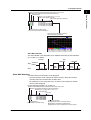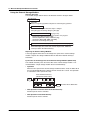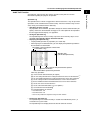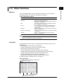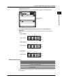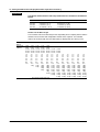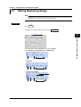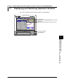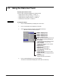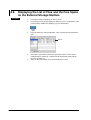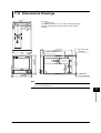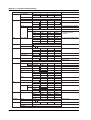
1
User’s
Manual
Model DX102P/DX104P/DX106P/DX112P
DAQSTATION DX100P
*
Yokogawa Electric Corporation
4
L
5 A 1
0
1 E 0
4
*
IM 04L05A01-01E
4th Edition
Tag
Filter
Moving average
#1
#2
Display
Group set/Trip line
Color
Zone
Graph
#5
#5 - #1
#5 - #2
#5 - #3
Time
Batch set
#8
#9
Item
Ref.section
5.1
5.2
5.10
5.9
5.16
5.6
5.8
Use/Not lot nember, Auto increment of lot
number, Headers 1 to 3
Set the date and time
5.17
5.15
Header string to be written to file
5.7
Name of directory to which data are to be saved
Display direction (trend, bar graph),
5.13
Background color, Trend line width, Trip line
width, Grid for the trend display, Interval for
switching group displays (Scroll time), Scale digit
LCD brightness
5.14
Turn On/Off the LCD backlight saver
Transition time for the LCD backlight saver and
conditions that restore the backlight
Zone upper and lower limits
5.11
Number of scale divisions for the trend and
5.12
bar graph, Bar graph base position, Scale
display position for trends
Turn On/Off partial expanded display
5.11
Position and boundary for the partial expanded display
Measurement channel display color
Group name, Assign channels to groups
Trip line position, display color
Group name and message strings
Trend display update rate, Auto save interval
Assign an action to the USER key
Tag name
5.3
Filter time constant/Off (DX102P/DX104P)
5.4
Number of samples for the moving average/Off 5.4
(DX106P/DX112P)
5.5
Input type, span, scale, etc.
Alarm type, Alarm value, Output relay On/Off
Output relay number
#7: [Save/Load] operations. #10 to #16: [Math set 1], [Math set 2], [Math set 3], [Calibration
Correction], [DST], [End], and [System Mode] are assigned.
File
LCD
View
#6
#5 - #4
Message
#4
Partial
Trend/Save interval
USER key
#3
Alarm delay time
Title
Range
Alarm
Soft key
Setting Items in the Engineering Mode
CUT ALONG THIS LINE
FOLD ALONG THIS LINE
DAQSTATION DX100P
Model DX102P/DX104P
DX106P/DX112P
Press the DISP/ENTER key to display the screen menu or the
operation screen.
Press the up, down, right, or left arrow key to select the
operation screen.
60
120
1h
480
4h
1200
10 h
Yokogawa Electric Corporation
43 h
125 ms 500 ms
Sampling length (approx.) 10 h
Sampling Interval (s)
5s
30 s
120 s
600 s
IM 04L05A01-01E
4th Edition
86 h 18 days 108 days 434 days 2170 days
1s
• When Acquiring the event data from four measurement channels
28 h 115 h 12 days 72 days 144 days 289days 1157 days 2893 days
30
15 min 30 min
Sampling length
(approx.)
10
0.5
Sampling Interval (s)
2
Display Update Rate 15 s 1 min 5 min
Sampling Interval and Sampling length for Display Data and Event Data (see
appendix 4)
• When Acquiring the display data from four measurement channels
DISP/
ENTER
Switching Operation Screens (see chapter 7)
Operation Screens (see section 1.3)
Trend / Digital/Bar graph / Information (Alarm Summary / Alarm ACK Summary /
Message Summary / Memory Summary) / Historical Trend / 4 Screen Display /
Sign Record Screen
Use this quick reference together with the user’s manual IM 04L05A01-01E.
Quick
Reference
Flow of operation (an example)
1 Login (6.1)
• Press the FUNC key.
• Enter the user name, user ID,
and the password.
• If you try to login using
incorrect passwords for three
consecutive times, the user
registration becomes invalid.
2 Operation preparation such as
changing settings
Press the MENU key to enter
the engineering mode.
3 Execute Memory Start by entering
the batch/lot No. (6.2)
• Press the START key.
• Enter the batch/lot No. and
comments.
• Set the cursor to [Start] and
press the DISP/ENTER key.
while running
4 Settings cannot be changed
5 Memory Stop (6.2)
6 Sign the data (6.3)
• Check the data.
• Sign to the data using the
assigned authority level.
• If you try to sign using
incorrect passwords for three
consecutive times, the user
registration becomes invalid.
7 Logout (6.1)
NOTE
Operations on the DX100P
Record of operations (Operation log, section 1.5)
Record of setting changes (Setting change log
and setup file, section 1.5)
Be sure to set a strage medium
to the drive.
Display data or event data file
(section 1.4)
• Batch/lot number
• Measured/computed data
• Name of the user who
executed Memory Start/
Memory Stop
Setup data used
Login information
Operation log
Alarm summary
Alarm ACK summary
Message summary
•
•
•
•
•
•
• Approval information
User name
Pass/fail
Comment
Enclosed in parentheses are reference sections.
To avoid injury, death of personnel or damage to the instrument, the
operator must refer to the explanation in the User’s Manual or Service
Manual.
FUNC
Writes messages.
Stops computation.
key function (see section 3.4)
Logs out.
Saves the display data.
Load the display/event data
in the external storage medium.
Saves a screen
image data.
Executes manual
sampling.
Enters the batch number
and lot number.
Startss computation. Saves the event data.
Resets computation.
ESC key
Setting screens
Soft keys
Menu screen
[End] soft key + DISP/ENTER key
[System mode]
soft key
+
DISP/ENTER key
Engineering mode
MENU or
ESC
Menu screen
Soft keys
Setting screens
System mode
Release the User locked icon.
Displays the MODBUS STATUS screen.
Retrieves time information
from a SNTP server.
Starts the e-mail.
Lists files in the external
Changes pssword.
storage medium.
Displays the log
screen.
Performs the e-mail
transmission test.
Performs the FTP test.
MENU key
Operation mode
Swtiching the Mode (see section 3.3)
Power ON
Login
Operation
screens
[End] soft key
+
DISP/ENTER key
When logged in
as a registered
administrator,
the system mode
can be entered.
IM 04L05A01-01E
Foreword
Thank you for purchasing the YOKOGAWA DAQSTATION DX100P.
This User’s Manual contains useful information about the functions, installation, wiring,
operating procedures, and troubleshooting of the DX100P. To ensure correct use,
please read this manual thoroughly before operation.
Keep this manual in a safe place for quick reference in the event a question arises.
In addition, a quick reference is provided on the previous page. This reference briefly
explains operations that are used frequently. Separate this reference from the manual
for use.
The following four manuals, including this one, are provided as manuals for the DX100P.
Manual Name
Manual No.
Description
DX100P User’s Manual
IM 04L05A01-01E
This manual. Explains all functions and
procedures of the DX100P excluding the
communication functions.
DX100P/DX200P
Operation Guide
IM 04L05A01-02E
Briefly explains basic operations of the
DX100P/DX200P.
DX100P/DX200P
Communication Interface
User’s Manual
IM 04L05A01-17E
Explains the communication functions of
the Ethernet/serial interface.
DAQSIGNIN
User’s Manual
IM 04L05A01-61E
Describes the functions and operating
procedures of DAQSIGNIN that comes with
the package.
Notes
• This manual describes the DX100P style number “S5.”
• The contents of this manual are subject to change without prior notice as a result of
continuing improvements to the DX100P’s performance and functions.
• Every effort has been made in the preparation of this manual to ensure the accuracy
of its contents. However, should you have any questions or find any errors, please
contact your nearest YOKOGAWA dealer.
• Copying or reproducing all or any part of the contents of this manual without
YOKOGAWA’s permission is strictly prohibited.
• The TCP/IP software used in this product and the documentation for that TCP/IP
software are based in part on BSD Networking Software, Release 1 licensed from The
Regents of the University of California.
Trademarks
• Microsoft, MS-DOS, Windows, and Windows NT are either registered trademarks or
trademarks of Microsoft Corporation in the United States and/or other countries.
• Zip is either a registered trademark or a trademark of Iomega Corporation in the
United States and/or other countries.
• Adobe, Acrobat, and PostScript are trademarks of Adobe Systems incorporated.
• For purposes of this manual, the TM and ® symbols do not accompany their
respective trademark names or registered trademark names.
• Company and product names that are used in this manual are trademarks or
registered trademarks of their respective holders.
Revisions
First edition
Second edition
Third edition
Fourth edition
December 2001
July 2002
November 2003
August 2004
Disk No. RE33
4th Edition: August 2004 (YK)
All Rights Reserved, Copyright © 2001 Yokogawa Electric Corporation
IM 04L05A01-01E
i
Safety Precautions
The following general safety precautions must be observed during all phases of
operation. If the DX100P is used in a manner not specified in this manual, the protection
provided by the DX100P may be impaired. YOKOGAWA Electric Corporation assumes
no liability for the customer’s failure to comply with these requirements.
This product is a measurement category II (CAT II) instrument.
*
Mesurement category II (CAT II)
Applies to measuring circuits connected to low voltage installation, and electrical instruments
supplied with power from fixed equipment such as electric switchboards.
The DX100P conforms to IEC safety class I (provided with terminal for protective
grounding), Installation Category II, and EN61326-1 (EMC standard), class A (use in a
commercial, industrial, or business environment).
Please use this instrument as a mesurement category II (CAT II) instrument.
This instrument is for indoor use only.
Symbols
The following symbols are used on the DX100P.
“Handle with care.” To avoid injury, death of personnel or damage to
the instrument, the operator must refer to the explanation in the User’s
Manual or Service Manual.
Functional ground terminal. Do not use this terminal as a protective
ground terminal.
Protective ground terminal.
AC
ON (power)
OFF (power)
Safety Precautions
Make sure to comply with the following safety precautions. Failure to comply may
result in injury or death (electric shock hazard).
WARNING
Power Supply
Before connecting the power cord, ensure that the power supply voltage
matches the voltage rating for the instrument, and for desktop types, that it is
within the maximum rated voltage for the power cord itself.
Power Cord and Plug (Desktop Type)
To prevent an electric shock or fire, be sure to use the power cord supplied by
YOKOGAWA. The main power plug must be plugged into an outlet with a
protective grounding terminal. Do not invalidate protection by using an extension
cord without protective grounding.
Protective Grounding
Make sure to connect the protective grounding to prevent electric shock before
turning ON the power.
ii
IM 04L05A01-01E
Safety Precautions
Necessity of Protective Grounding
Never cut off the internal or external protective grounding wire or disconnect the
wiring of the protective grounding terminal. Doing so poses a potential shock
hazard.
Defect of Protective Grounding
Do not operate the instrument when the protective grounding or the fuse might
be defective. Also, make sure to check them before operation.
Fuse
To prevent fire, only use a fuse that has a rating (voltage, current, and type) that
is specified by the instrument. When replacing a fuse, turn OFF the power
switch and unplug the power cord. Never short the fuse holder.
Do Not Operate in Explosive Atmosphere
Do not operate the instrument in the presence of flammable liquids or vapors.
Operation of any electrical instrument in such an environment constitutes a
safety hazard.
Do Not Remove Covers
Some areas inside the instrument have high voltages. Do not remove the cover
if the power supply is connected. The cover should be removed by
YOKOGAWA’s qualified personnel only.
External Connection
Connect the protective grounding before connecting to the item under
measurement or control unit.
Damage to the Protection
Using the instrument in a manner not specified in this manual can damage the
instrument’s protection.
Safety Precautions in Handling the Batteries
WARNING
• Abide by the following precautions in handling the batteries. If the
batteries are not handled correctly, dangerous conditions may result such
as the batteries exploding or leaking.
• Insert the batteries according to the polarity indicated on the remote control
terminal.
• Use only the specified batteries.
• Do not mix different types of batteries.
• Do not mix new and old batteries.
• Do not short the positive and negative terminals of the batteries.
• Do not charge the batteries.
• If the remote control terminal is not going to be used for an extended time,
remove the batteries from the remote control terminal.
• Dispose the batteries correctly. Do not burn or disassemble the batteries.
• Do not use batteries that are leaking.
• If the battery liquid comes in contact with your hands or face, thoroughly
wash using water.
Exemption from Responsibility
• YOKOGAWA makes no warranties regarding the product except those stated in the
WARRANTY that is provided separately.
• YOKOGAWA assumes no liability to any party for any loss or damage, direct or
indirect, caused by the user or any unpredictable defect of the product.
IM 04L05A01-01E
iii
Checking the Contents of the Package
Unpack the box and check the contents before operating the DX100P. If some of the
contents not correct or missing or if there is physical damage, contact the dealer from
which you purchased them.
DX100P Main Unit
There is a name plate on the back side of the key panel cover. Open the cover and check
that the model name and suffix code given on the name plate match those on the order.
Panel mount type
Desktop type
MODEL
STYLE
SUFFIX
SUPPLY
FREQUENCY
NO
Made in Japan
MODEL
STYLE
SUFFIX
MODEL
SUFFIX
STYLE
NO
SUPPLY
FREQUENCY
NO
Made in Japan
MODEL
Model code
DX102
DX104
DX106
DX112
External storage
medium
Language
Options
*1
*2
*3
*4
*5
*6
*7
*8
iv
Suffix code Optional code
–2
–3
–5
–2
/AR1
/AR2
/A3
/C2
/C3
/F1
/H2
/H5[ ]
/M1
/N1
/N2
/P1
/R1
/TPS2
/TPS4
/KB1
/KB2
/CC1
Description
DAQSTATION DX100P (2 ch)
DAQSTATION DX100P (4 ch)
DAQSTATION DX100P (6 ch)
DAQSTATION DX100P (12 ch)
100 MB Zip disk
Flash memory card
250 MB Zip disk
English, deg.F/DST (DAQSIGNIN included)
Alarm output relay (2 relays)/remote control*1
Alarm output relay (4 relays)/remote control*1
Alarm output relay (6 relays)*1
RS-232 interface*2
RS-422-A/485 interface*2
FAIL/memory end output relay*3
Clamped input terminal
Desktop type*4
Computation function (report function included)
Cu10, Cu25 RTD input/3 terminal isolated RTD
3 terminal isolated RTD*5
24 VDC/AC power supply
Remote control
24 VDC Power supply for transmitter(2 loops)*6
24 VDC Power supply for transmitter(4 loops)*7
Easy Text Entry (with remote control)*8
Easy Text Entry (without remote control)*8
Calibration Correction
/AR1, /AR2, and /A3 cannot be specified simultaneously
/C2 and /C3 cannot be specified simultaneously.
If /F1 is specified, /A3 cannot be specified.
/H5: Can only be specified when /P1 is simultaneously specified., /H5D: UL, CSA cable, /H5F: VDE cable,
/H5R: SAA cable, /H5J: BS cable
/N2 can only be specified on DX106, and DX112 models.
If /TPS2 is specified, /TPS4, /AR2, /A3 and /F1 cannot be specified.
If /TPS4 is specified, /TPS2, /AR1, /AR2, /A3 and /F1 cannot be specified.
/KB1 and /KB2 cannot be specified simultaneously.
IM 04L05A01-01E
Checking the Contents of the Package
NO. (Serial No.)
When contacting the dealer from which you purchased the DX100P, please quote the
serial No.
Standard Accessories
The following standard accessories are supplied with the DX100P. Make sure that all
items are present and undamaged.
2
1
/H5D
3
5
4
/H5J
/H5F
/H5R
6
/H5H
7. One of these power cord types is supplied according to the instrument’s suffix code
ID No.
8
IM 04L05A01-01E
Number Part Name
Part Number/Model Q’ty Notes
1
A1347EF
1
A1352EF
1
2
Terminal screw
5
M4, for supplementary use
3
Mounting bracket B9900BX
2
For panel mounting (except /H5[ ]
models)
4
User’s Manual
IM 04L05A01-01E
1
This manual
User’s Manual
IM 04L05A01-17E
1
DX100P/DX200P Communication
Interface
User’s Manual
IM 04L05A01-61E
1
DAQSIGNIN
User’s Manual
IM 04L05A01-02E
5
Application
software
(DAQSIGNIN)
DXA150-02
1
Included only when the suffix code
for language is “-2.”
For Windows 98, Windows Me,
Windows NT4.0, Windows 2000,
Windows XP.
Provided on a CD.
6
External storage
medium
A1053MP
1
A1056MP
1
B9968NL
1
Zip disk (100 MB), included only
when the suffix code for external
storage medium is “-2.”
Zip disk (250 MB), included only
when the suffix code for external
storage medium is “-5.”
Flash memory card (32–MB CF card
+ adapter, capacity and model of the
CF card may vary). Provided only
when the suffix code for the external
storage medium is “-3.”
Fuse
250 V 1 A, time lag (except /P1
model)
250 V 4 A, time lag (/P1 model)
DX100P/DX200P Operation Guide
v
Checking the Contents of the Package
Number Part Name
Part Number/Model Q’ty Notes
7
A1006WD
1
A1009WD
1
A1024WD
1
A1023WD
1
A1064WD
1
438227
1
8
Power cord
Remote control
Provided only when “/H5D” is
specified for the optional code.
Maximum rated power voltage: 125 V
Provided only when “/H5F” is
specified for the optional code.
Maximum rated power voltage: 250 V
Provided only when “/H5R” is
specified for the optional code.
Maximum rated power voltage: 250 V
Provided only when “/H5J” is
specified for the optional code.
Maximum rated power voltage: 250 V
Provided only when “/H5H” is
specified for the power supply code.
(complies with the CCC) Maximum
rated power voltage: 250 V
Provided only when “/KB1” is terminal
specified for the optional code.
Alkaline batteries (2 pieces), an ID
code entry label, and a character
label are included.
Optional Accessories (Sold Separately)
The following optional accessories are available for purchase separately. If you make an
order, make sure that all items are present and undamaged.
For information about ordering accessories, contact the dealer from which you
purchased the DX100P.
vi
Number
Part Name
Part Number/Model
Q’ty
Notes
1
Zip disk
A1053MP
A1056MP
1
1
100 MB
250 MB
2
Flash memory card
(CF card + adapter)
B9968NL
1
32–MB card
(capacity and model of
the CF card may vary,
please be careful when
ordering)
3
Shunt resistor
(for the screw terminal)
4159 20
4159 21
4159 22
1
1
1
250 Ω ±0.1%
100 Ω ±0.1%
10 Ω ±0.1%
4
Shunt resistor
(for the clamped
input terminal)
4389 20
4389 21
4389 22
1
1
1
250 Ω ±0.1%
100 Ω ±0.1%
10 Ω ±0.1%
5
Fuse
A1347EF
4
A1352EF
4
250 V 1 A time lag
(except /P1 model)
250 V 4 A, time lag (/P1
model)
B9900BX
2
6
Mounting bracket
7
Remote control terminal
438227
1
8
Validation Document
for DX100P
438221
438222
438223
1
1
1
Electronic file
A4 size paper
Letter size paper
IM 04L05A01-01E
How to Use this Manual
Structure of the Manual
This user’s manual consists of the following sections.
For details on the communication functions and DAQSIGNIN provided with the package,
see the respective manuals (IM 04L05A01-17E and IM 04L05A01-61E).
Chapter
Title and Description
1
Overview of Functions
Describes the functional overview of the DX100P.
2
Before Using the DX100P
Describes the names of each part of the DX100P and how to install and wire the
DX100P.
3
Common Operations
Describes how to use the storage medium drive, run mode, and common key
operations.
4
Settings in the System Mode
Describes how to set various items in the system mode.
5
Settings in the Engineering Mode
Describes how to set various items in the engineering mode.
6
Basic Operation (Operation Mode)
Describes the procedures from logging in and recording measured data to adding
approval information to the recorded result.
7
Switching Operation Screens
Describes how to use the operation screen such as the trend screen and digital
screen. Describes the operations that can be performed using the arrow keys
and the DISP/ENTER key on the front panel.
8
Other Operations (Operations Using the FUNC and USER Keys)
Describes the operations that can be performed using the FUNC and USER
keys.
9
Troubleshooting
Describes the error messages and the troubleshooting measures of the DX100P.
10
Maintenance
Describes fuse replacement and other information.
11
Specification
Describes the specifications of the DX100P.
Appendix
Describes the parameters and initial values of the engineering mode and system
mode, data formats of ASCII files, types of data that the DX100P generates, and
the time for acquiring display data and event data to the internal memory.
Index
Note
This manual covers information regarding DX100Ps that have a suffix code for language “-2”
(English).
For details on setting the displayed language, see section 4.9.
IM 04L05A01-01E
vii
How to Use this Manual
Conventions Used in This Manual
Unit
K ....... Denotes “1024.” Example: 768 KB (File capacity)
k ........ Denotes “1000.”
M ....... Denotes “1024K.” Example: 100 MB
B ....... “Bytes.” Example: 100 MB
Symbols
The following symbols are used in this manual.
Improper handling or use can lead to injury to the user or
damage to the instrument. This symbol appears on the
instrument to indicate that the user must refer to the user’s
manual for special instructions. The same symbol appears in
the corresponding place in the user’s manual to identify those
instructions. In the manual, the symbol is used in conjunction
with the word “WARNING” or “CAUTION.”
WARNING
Describes precautions that should be observed to prevent injury
or death to the user.
CAUTION
Describes precautions that should be observed to prevent minor
or moderate injury, or damage to the instrument.
Note
Provides important information for the proper operation of the
instrument.
Reference
⇒“ ”
Indicates a reference item.
Example: ⇒ “3.6 Entering Numbers and Characters”
Notation Regarding Procedures
On pages that describe the operating procedures in Chapter 3 through 8, the following
symbols are used to distinguish the procedures from their explanations.
[ ]
Represents contents that are displayed on the screen.
Example: [Volt]
#1
Denotes the soft key that is used to make a selection on the
engineering and system mode menus.
Procedure
Follow the steps indicated with numbers. The procedures are
given with the premise that the user is carrying out the steps for
the first time. Depending on the operation, not all steps need to
be taken.
Explanation
This section describes the setting parameters and the
limitations regarding the procedures. It does not give a detailed
explanation of the function. For detail on the function, see
chapter 1.
viii
IM 04L05A01-01E
1
Contents
Foreword ......................................................................................................................................... i
Safety Precautions .......................................................................................................................... ii
Checking the Contents of the Package .......................................................................................... iv
How to Use this Manual ................................................................................................................ vii
3
Chapter 1 Overview of Functions
1.1
1.2
1.3
1.4
1.5
1.6
1.7
1.8
1.9
1.10
2
Overview of the DX100P .................................................................................................. 1-1
Functions of the Input Section ......................................................................................... 1-2
Display Function .............................................................................................................. 1-6
Measured/Computed Data Save Function ..................................................................... 1-20
Function for Managing Measured/Computed Data ........................................................ 1-31
Alarm Function ............................................................................................................... 1-39
Computation Function and Report Function (/M1 Option) ............................................. 1-43
FAIL/Memory End Output Function (/F1 option) ............................................................ 1-51
Remote Control Function (/R1 Option) .......................................................................... 1-53
Other Functions ............................................................................................................. 1-55
4
5
6
Chapter 2 Before Using the DX100P
2.1
2.2
2.3
2.4
2.5
2.6
2.7
2.8
2.9
Precautions on the Use of the DX100P ........................................................................... 2-1
Names of Parts and Functions ......................................................................................... 2-3
Installing the DX100P ...................................................................................................... 2-6
Input Signal Wiring ........................................................................................................... 2-8
Alarm Output Wiring (/AR1, /AR2, /A3 Option) .............................................................. 2-12
FAIL/Memory End Wiring (/F1 Option) ........................................................................... 2-14
Remote Control Wiring (/R1 Option) .............................................................................. 2-15
24 VDC Transmitter Power Supply Wiring (/TPS2, /TPS4, Option) ............................... 2-16
Power Supply Wiring ...................................................................................................... 2-18
7
8
9
Chapter 3 Common Operations
3.1
3.2
3.3
3.4
3.5
3.6
3.7
Turning ON/OFF the Power ............................................................................................. 3-1
Inserting/Removing the External Storage Medium .......................................................... 3-2
Run Mode ........................................................................................................................ 3-4
Operations in the Operation Mode ................................................................................... 3-5
Setting the Functions (System Mode and Engineering Mode) ......................................... 3-7
Entering Numbers and Characters ................................................................................ 3-22
Using the Remote Controll Terminal .............................................................................. 3-24
Chapter 4 Configuration in the System Mode
4.1
4.2
4.3
4.4
4.5
4.6
4.7
4.8
4.9
4.10
IM 04L05A01-01E
Setting the Auxiliary Alarm Function ................................................................................ 4-1
Setting the A/D Integration Time, Scan Interval, Burnout, Reference Junction
Compensation, and Temperature Unit ............................................................................. 4-3
Setting the Method of the Display/Event Data Acquisition and Saving ............................ 4-5
Registering Users and Setting the Login Function and Electronic Signature Function .... 4-9
Assigning Actions to the Remote Control Terminals (/R1 Option) ................................. 4-16
Setting the Report Function ........................................................................................... 4-17
Setting the Timer for TLOG Data Acquisition and TLOG Computation .......................... 4-19
Setting System Relays (/F1 Option) ............................................................................... 4-21
Setting the Auxiliary Functions ....................................................................................... 4-22
Setting the Time Zone .................................................................................................... 4-24
ix
10
11
App
Index
Contents
4.11
4.12
4.13
4.14
4.15
4.16
Saving/Loading Setup Data ........................................................................................... 4-25
Loading the Login Information ....................................................................................... 4-28
Clearing the Data in the Internal Memory and Initializing the Setup Data ..................... 4-29
Setting Items That Are Allowed to Be Changed While Data Acquisition Is in Progress . 4-30
Setting the Time Deviation Limit for Time Correction ..................................................... 4-31
Using the Storage Area of the External Storage Medium Cyclically
(FIFO Operation of the Storage Media) ......................................................................... 4-32
Chapter 5 Configuration in the Engineering Mode
5.1
5.2
5.3
5.4
5.5
5.6
5.7
5.8
5.9
5.10
5.11
5.12
5.13
5.14
5.15
5.16
5.17
5.18
5.19
5.20
5.21
5.22
5.23
5.24
Setting Measuring Range ................................................................................................ 5-1
Setting Alarm .................................................................................................................... 5-5
Setting Tag Names ........................................................................................................... 5-7
Setting Input Filter and Moving Average .......................................................................... 5-8
Setting the Alarm Delay Period ........................................................................................ 5-9
Setting the Display Update Rate and Auto Save Interval ............................................... 5-10
Setting the File Header and Directory Name ................................................................. 5-12
Assigning an Action to the USER Key ........................................................................... 5-13
Setting Groups and Trip Lines ....................................................................................... 5-14
Setting the Channel Display Colors (Trend, Bar Graph) ................................................ 5-16
Setting Zone Displays/Partial Expanded Displays (Trend) ............................................ 5-17
Setting the Scale Division, Bar Graph Base Position (Bar Graph), and Scale Position
(Trend) ........................................................................................................................... 5-19
Setting the Display Direction, Background Color, Waveform Line Width, Trip Line Width,
Grid, Scroll Time, and Scale digit ................................................................................... 5-24
Setting the Brightness of the Screen and the Backlight Saver Function ........................ 5-26
Setting the Date and Time ............................................................................................. 5-27
Setting the Message String ............................................................................................ 5-28
Setting the Batch Information ......................................................................................... 5-29
Setting Equations, Alarms, and Constants for Computation Channels (/M1 Option) ..... 5-30
Setting the Timer Number and Sum Scale for TLOG Computation (/M1 Option) .......... 5-38
Setting the Rolling Average (/M1 Option) ....................................................................... 5-39
Setting the Calibration Correction (/CC1 Option) ........................................................... 5-40
Setting the DST .............................................................................................................. 5-42
Saving/loading the Setup Data ...................................................................................... 5-43
Saving the Data in the Internal Memory to the External Storage Medium Using Keys .. 5-45
Chapter 6 Basic Operation
6.1
6.2
6.3
Login/Logout .................................................................................................................... 6-1
Executing Memory Start/Memory Stop ............................................................................ 6-4
Signing Display Data/Event Data ..................................................................................... 6-6
Chapter 7 Switching Operation Screens (Operations Using the Arrow Keys
and DISP/ENTER Key)
7.1
7.2
7.3
7.4
7.5
x
Displaying and Switching Operation Screens .................................................................. 7-1
Using the Trend, Digital, and Bar Graph Screens ............................................................ 7-3
Using the Overview Screen ............................................................................................. 7-8
Using the Information Screen (Alarm Summary, Alarm ACK Summary,
Message Summary, and Memory Summary) ................................................................... 7-9
Using the Historical Trend .............................................................................................. 7-12
IM 04L05A01-01E
Contents
1
Chapter 8 Other Key Operations
8.1
8.2
8.3
8.4
8.5
8.6
8.7
8.8
8.9
8.10
8.11
8.12
Setting the Batch Number, Lot Number, and Comment ................................................... 8-1
Writing Messages Strings (Trend) .................................................................................... 8-3
Storing Measured/Computed Data at Arbitrary Times (Manual Sampling) ...................... 8-5
Starting/Stopping Computation, Resetting Computation, Releasing Computation Dropout
Display (/M1 Option) ........................................................................................................ 8-6
Saving the Screen Image (Snap Shot) ............................................................................ 8-8
Saving the Display Data/Event Data to the External Storage Medium
Using Key Operation ........................................................................................................ 8-9
Signing Display/Event Data Files on the External Storage Medium .............................. 8-10
Displaying the List of Files and the Free Space on the External Storage Medium ........ 8-12
Displaying the Log Screen/System Screen .................................................................... 8-13
Changing the Password ................................................................................................. 8-16
Acknowledging Alarms (Alarm ACK) .............................................................................. 8-17
Clearing the User Locked Icon ....................................................................................... 8-18
2
3
4
5
Chapter 9 Troubleshooting
9.1
9.2
A List of Messages ........................................................................................................... 9-1
Troubleshooting Flow Chart ........................................................................................... 9-13
6
Chapter 10 Maintenance
10.1
10.2
10.3
10.4
Periodic Maintenance .................................................................................................... 10-1
Replacing the Fuse ........................................................................................................ 10-2
Calibration ...................................................................................................................... 10-3
Recommended Replacement Periods for Worn Parts ................................................... 10-5
8
Chapter 11 Specifications
11.1
11.2
11.3
11.4
11.5
11.6
11.7
11.8
11.9
Input Specifications ........................................................................................................ 11-1
Display Specifications .................................................................................................... 11-3
Data Storage Specifications ........................................................................................... 11-5
Alarm Function Specifications ........................................................................................ 11-7
Specifications of the Function Used to Manage the Data .............................................. 11-8
Specifications of Communication Functions ................................................................ 11-10
Specifications of Optional Functions ............................................................................ 11-11
General Specifications ................................................................................................. 11-16
Dimensional Drawings ................................................................................................. 11-21
9
10
11
Appendix
Appendix 1
Appendix 2
Appendix 3
Appendix 4
Appendix 5
Appendix 6
Parameters and Initial Settings ......................................................................... App-1
Data Formats of ASCII Files ............................................................................ App-10
Data Type ........................................................................................................ App-15
Time for Acquiring Display Data/Event Data to the Internal Memory .............. App-16
Operation Log Contents and Display .............................................................. App-18
Style Numbers and Functions ......................................................................... App-20
App
Index
Index
IM 04L05A01-01E
7
xi
Chapter 1 Overview of Functions
1.1
1
Overview of the DX100P
Overview of Functions
Unlike conventional recorders that record data on charts, the DX100P displays the
measured data acquired in the internal memory to a LCD in the form of waveforms,
numerical values, and bar graphs. The measured data can also be saved to external
storage media such as Zip disks and flash memory cards.
DX100P
External storage medium
Zip disk
Flash memory card
1
2
DISP/
ENTER
3
4
The measured data are managed as follows:
• Only registered users can operate the DX100P.
• The batch number and lot number can be attached to the measured data files.
• Operations and setting changes are recorded in the order of occurrence.
• Up to three users can add approval information to the measured data file.
Communication Function (See IM 04L05A01-17E)
You can carry out the following types of operations by using the Ethernet communication
function.
• Transmit the measured data in units of files to the server on the network (FTP client
function).
• Load the measured data on the DX100P, configure and operate the DX100P from a
PC on the network (setting/measurement server function).
• Retrieve the files on the external storage medium of the DX100P from a PC on the
network (FTP server function).
• Display the screen of the DX100P on a Web browser on a PC (Web server function).
• Transmit e-mail messages to preset recipients when events occur (e-mail
transmission function).
• Synchronize to the time on an SNTP server on the network (SNTP client function).
• Transmit time information to clients on the network as an SNTP server (SNTP server
function).
DX100P
PC
Time data
PC
Configures and operates
the DX100P.
Loads the measured
data and files.
E-mail/Web screens
Time data
The DX100P transfers
measured data files.
FTP server
Primary
Secondary
SNTP server
DAQSIGNIN (See IM 04L05A01-61E)
By using the DAQSIGNIN that comes standard with the DX100P, the following
operations are possible.
• Adding approval information to the measured data file
• Converting the measured data to ASCII, Lotus, or Excel formats
• Configuring the setup file for the DX100P
• Receiving the setup data from the DX100P, sending the setup data to the DX100P via
the Ethernet interface.
IM 04L05A01-01E
1-1
1.2
Functions of the Input Section
Number of Measurement Channels/Scan Interval
The number of measurement channels and scan intervals for different models are listed
in the table below. For the procedure related to setting the scan interval, see section 4.2.
Model
Number of Measurement Channels
Scan interval
DX102P
DX104P
DX106P
DX112P
2 channels
4 channels
6 channels
12 channels
125 ms or 250 ms
125 ms or 250 ms
1 s or 2 s
1 s or 2 s
Input Type and Computation
You can select the input type of a measurement channel from DC voltage, thermocouple,
resistance temperature detector (RTD), and digital input (contact signal or voltage
signal). For the setting procedure, see section 5.1.
Input type
Description
Measures a DC voltage in the range ±20 mV to ±50 V.
See the explanation below.
Measures the temperature corresponding to the appropriate range for
R, S, B, K, E, J, T, N, W, L, and U.
Resistance temperature Measures the temperature corresponding to the appropriate range for
detector (RTD)
Pt100, JPt100, Cu10*, and CU25.*
Digital input (DI)
Displays the contact input or voltage input signals by correlating them to
0% or 100% of the display range.
Contact input: Closed contact is “1.” Open contact is “0.”
Voltage input: Less than 2.4 V is “0.” Greater than or equal to 2.4 V is
“1.”
DC voltage
DC current
Thermocouple (TC)
* Cu10 and CU25 are optional (/N1).
DC Current Input
A shunt resistor is attached to the input terminal. The current signal is converted to a
voltage signal and measured. The measurable range is the range equivalent to the “DC
voltage” range indicated above after converting the current to the voltage signal. A 250
Ω shunt resistor, for example, is used to convert a 4 to 20 mA to a 1 to 5 V.
Name
Model Code
Specification
Shunt resistors
(for screw terminals)
4159 20
4159 21
4159 22
250 Ω ±0.1%
100 Ω ±0.1%
10 Ω ±0.1%
Shunt resistors
(for clamped terminals)
4389 20
4389 21
4389 22
250 Ω ±0.1%
100 Ω ±0.1%
10 Ω ±0.1%
Input Range and Measurable Range
You can select the “Input range” that is appropriate for the input signal for “DC voltage,”
“TC,” “RTD,” and “DI” (for example, R, S, B, K, E, J, T, N, W, L, and U are available input
ranges for “TC”). For each “Input range,” a measurable range is defined (for example,
the measurable range for R of “TC” is “0.0°C to 1760°C”). For details, see section 5.1.
You can specify an arbitrary range within the measurable range as a display span.
Measurable range (Example: TC Type R)
1760.0°C
Display span
1500.0°C(Upper limit of the display span)
300.0°C(Lower limit of the display span
0.0°C
1-2
IM 04L05A01-01E
1.2 Functions of the Input Section
1
Computation
Difference computation
+
Measured
value
Input value
−
Measured value of the reference channel
Note
Even if the input type or the measurement range of the difference computation channel and
the reference channel is not the same, the difference computation is performed according to
the following rules.
• When the decimal position between the reference channel and the difference computation
channel is different, the measured value of the reference channel is adjusted to the decimal
position of the measured value of the difference computation channel to make the computation.
Example: When the measured value of the difference computation channel is 10.00 and
the measured value of the reference channel is 100.0, the computation result
becomes 10.00 – 100.0 = –90.00.
• When the units for the reference channel and the difference computation channel are
different, the measured value is not adjusted.
Example: When the measured value of the difference computation channel is 10.00 V
and the measured value of the reference channel is 5.00 mV, the computation
result becomes 10.00 V – 5.00 mV = 5.00 V.
• When the reference channel is set to [Scale] or [Sqrt], the computation uses the scaled values.
•
When the calibration correction (see next page) is applied to the channel, values after
correction is used for the computation.
Scaling
When the input type is set to “DC voltage,” “thermocouple,” “RTD,” or “digital input,” the
input value is converted to a value in the appropriate unit and the converted value
becomes a measured value of the channel.
Scaling
Square root computation
Input value
5V
Measured value
300.0 °C
Input value
Input value
1V
√
Scaling
Measured
value
−100.0 °C
Square Root
When the input type is set to “DC voltage,” the square root of the input value is
computed. The computed result is scaled to a value in the appropriate unit and the
scaled value becomes a measured value of the channel.
Note
•
The DX100P uses the following square-root computation:
Fx = (F max – Fmin )
•
IM 04L05A01-01E
Vx – Vmin
V max – Vmin
+ F min
• Vmin: Lower limit of span • Fmin: Lower limit of scale • Vx: Input voltage
• Vmax: Upper limit of span • Fmax:Upper limit of scale • Fx: Scaling value
When the value inside the square root is negative, the measured value is indicated as
when Fmin < Fmax: “–
,” or when Fmin > Fmax: “+
”.
1-3
Overview of Functions
You can also perform computation on the input values such as the “difference,” “square
root,” and “scaling.” For the setting procedure, see section 5.1.
Difference Computation
The value obtained by subtracting the measured value of another channel (this channel is
called a “reference channel”) from the input value becomes a measured value of the channel.
1.2 Functions of the Input Section
Calibration Correction (/CC1 Option)
Corrects the measured value of each channel using ten-segment linearizer
approximation and makes the resultant value the measured value of the channel.
You can set arbitrary true values (measured values after correction) for up to 16 points of
arbitrary measured values. Linear approximation is used between two segment points.
For the setting procedure, see section 5.21.
True value
(measured value after correction)
Input processing
Y5
Input value
Y4
(Moving average/Filter)
(Square root computation)
(Scaling)
X
Y3
Calibration correction
Y2
Y
Y1
X1 X2
X3 X4
X5
Measured value
(measured value before correction)
(Difference computation)
Displayed on the screen
Burnout
When measuring temperature using a thermocouple and the thermocouple burns out,
you can specify the measurement result to be set to positive over range* or negative over
range.* Burnout can be set on each measurement channel. For the setting procedure,
see section 4.2.
*
Positive over range is a condition in which the input signal is over the upper limit of the
measurable range. The measured value is indicated as “+
.”
Negative over range is a condition in which the input signal is below the lower limit of the
measurable range. The measured value is indicated as “.”
Note
•
•
When the alarm is set to detect positive or negative over range, the occurrence of burnout of
thermocouple can be displayed as an alarm.
Turn the burnout function OFF when connecting the input wires in parallel with other devices.
Reference Junction Compensation (RJC)
When measuring the temperature using a thermocouple, the reference junction
compensation can be used. You can select whether to use the reference junction
compensation provided by the DX100P or external reference junction compensation. If
you are using external reference junction compensation, you will also set the reference
voltage. For the setting procedure, see section 4.2.
Note
•
•
When using the reference junction compensation of the DX100P, see “Precautions to be
taken while wiring” in section 2.4, “Input Signal Wiring.”
When using the external reference junction compensation, set an appropriate reference
junction compensation voltage. As in the example in the following figure, if the reference
junction temperature for the external reference junction compensation is T0 °C, set the
thermoelectromotive force of the 0 °C reference for T0 °C as the reference junction
compensation voltage.
An example of External reference junction compensation
External reference junction compensation
DX100P
(Maintain the junction between the thermocouple
and the copper wire at T0 °C)
Copper wire
1-4
Thermocouple
IM 04L05A01-01E
1.2 Functions of the Input Section
1
Filter and Moving Average
Effects of using filter(Output response fot a step input)
Input
63.2% of the output value
Output response curve (when using the filter)
2, 5, 10 s (time constant, the time it takes to reach 63.2% of the output value)
Moving Average (DX106P and DX112P)
The input signal of the measurement channel is set to the averaged value of the m most
current data points (the number of moving-averaged data points) acquired at the scan
interval. The number of moving-averaged data points can be set in the range 2 to 16.
The figure below shows an example indicating the operation of the buffer for the moving
average computation when the number of moving-averaged data points is set to “5.”
Buffer data at the
nth sampling
Buffer data at the
n+2th sampling
New data
Buffer data at the
n+1th sampling
New data
1
10.0mV
15.0mV
10.0mV
2
5.0mV
10.0mV
15.0mV
3
0.0mV
5.0mV
10.0mV
4
–5.0mV
0.0mV
5.0mV
5
–10.0mV
–5.0mV
Deleted
Moving average value
0.0mV
0.0mV
Deleted
5.0mV
8.0mV
Integration Time of the A/D Converter
The DX100P uses an A/D converter to convert the sampled analog signal to a digital
signal. By setting the integration time to match the time period corresponding to one
cycle of the power supply or an integer multiple of one cycle, the power supply frequency
noise can be effectively eliminated.
The integration time of the A/D converter is selected from the table below.
Model
Integration Time of the A/D Converter
DX102P/DX104P
Select 16.7 ms (60 Hz), 20 ms (50 Hz), or Auto
DX106P/DX112P
Select 16.7 ms (60 Hz), 20 ms (50 Hz), 100 ms, or Auto
• If “Auto” is selected, the DX100P will automatically detect the power supply frequency
and select 16.7 ms or 20 ms. However, the integration time is fixed to 20 ms on /P1
models that use the 24 VDC power supply.
• Because 100 ms is an integer multiple of 16.7 ms and 20 ms, this setting can be used
to eliminate the power frequency noise for either frequency, 50 Hz or 60 Hz. 100 ms
is available on the DX106P and DX112P. However, when the integration time is 100
ms, the scan interval is fixed to 2 s.
For the setting procedure, see section 4.2.
IM 04L05A01-01E
1-5
Overview of Functions
The filter and moving average are used to suppress the effects of noise that is riding on
the signal. Filtering is provided on the DX102P and DX104P. Moving average is
provided on the DX106P and DX112P. The filter or moving average can be set on each
channel. For the setting procedure, see section 5.4.
Filter Function (DX102P and DX104P)
Suppresses the effects of noise above the frequency determined by the specified time
constant. The time constant can be set to 2 s, 5 s, or 10 s.
1.3
Display Function
Common Items Related to the Display
5.5” TFT Color LCD and the Screen Configuration
The DX100P has a 10.4” TFT color LCD (240-by-320 dot resolution). The screen
consists of the status display section and the data display section.
Status display section
Data display section
• Status Display Section
Displays the displayed screen name, date and time or batch number/lot number, user
name, internal memory/external storage medium usage condition, alarm condition,
and computation condition (/M1 option). For details, see page 1-18.
• Data Display Section
Displays measured/computed data* using numerical values, waveforms, bar graphs,
and so on. Shows the setup screen when setting functions.
*
The measured values of measurement channels and the computed values of computation
channels (/M1 option) of the DX100P including the time information when they are acquired
are called "measured data" and "computed data," respectively.
Group Display
The data displayed on the trend, digital, and bar graph screens are the data of
measurement or computation channels that are assigned to the group. Up to 6 channels
can be assigned to a single group. Up to 6 groups can be registered. The groups are
common to the trend, digital, and bar graph screens. For the procedure used to assign
channels to groups, see section 5.9.
On the trend, digital, and bar graph screens, the displayed groups can be automatically
switched at 5 s, 10 s, 20 s, 30 s, or 1 min intervals. For the setting procedure, see
section 5.13.
Channel Number or Tag Name Display
The channels can be displayed as channel number or tags. The setting applies to all
channels. For the setting procedure, see sections 4.9 and 5.3.
Alarm Indication
Alarms are checked at all times and displayed on the relevant screens using alarm type
symbols. For details related to setting alarms, see sections 4.1, 5.2, and 5.18.
1-6
Name
Symbol
|
Name
Symbol
Upper limit alarm
Lower limit alarm
Difference upper limit alarm
Difference lower limit alarm
H
L
h
l
|
|
|
|
Upper limit on rate-of-change alarm
Lower limit on rate-of-change alarm
Delay upper limit alarm
Delay lower limit alarm
R
r
T
t
IM 04L05A01-01E
1.3 Display Function
1
Trend Screen
Trend (Vertical)
Scale
Display update rate(Time/div)
Message
Trip line
Tag/Channel no.
Measured/computed value
Unit
Alarm mark
Numerical display section
Trend (Vertical, All channel display)
Waveform for all channels that are
registered to display the trend
Data from selected group
Trend Display (Horizontal, Type 1)
Trend Display (Horizontal, Type 2)
Updating the Waveform and Updating the Numerical Display
One division along the time axis consists of 30 dots on the LCD. The displayed
waveform is updated at an interval corresponding to one dot. This interval is determined
by the time period corresponding to one division (referred to as the display update
rate). For the procedure related to setting the display update rate, see section 5.6. The
relationship between the display update rate and the speed of movement of waveforms
is as follows:
Display Update Rate (/div)
15 s*1 30 s*1 1 min 2 min 5 min 10 min 15 min 20 min 30 min 1 h
Interval corresponding
to one dot (s)
0.5
1
2
Speed of movement of waveforms*2 2376 1188 594
(approximate value, mm/h)
2h
4 h 10 h
4
10
20
30
40
60
120 240 480 1200
297
119
59
40
30
20
10
5
2.5 1.0
*1 for DX102P and DX104P only
*2 Speed of movement of waveforms = 30 (dots) × 0.33 mm (dot pitch) × 60 min / [display
update rate (min)]
Measured/computed values are updated every second. However, when the scan
interval on the DX106P/DX112P is 2 s, the update rate is also 2 s.
IM 04L05A01-01E
1-7
Overview of Functions
Displays the waveform of the measured and computed data. The direction of the
waveform display can be set to horizontal or vertical. For details related to the display
method, see section 7.2.
1.3 Display Function
Displayed Data
The data displayed on the screen are a maximum and minimum values of the data that
are sampled at the scan interval, within the time period corresponding to one dot.
Displayed data of the waveform (when the display update rate is set to one minute)
} 2 s (1 dot)
Maximum value
1 division (30 dots)
=1 min.
Minimum value
When the display update rate is set to one minute,
the time period corresponding to one dot (the
sampling interval of displayed data) is 2 s.
Displayed Information
The following Information can be displayed.
Information
Description
All channel display
Waveforms of all channels that were set to display the trend are displayed on one trend screen.
⇒“Sections 4.3 and 7.2”
Message writing
Specified messages can be written at arbitrary points in time. Messages are written to the
internal memory and displayed on the waveform display section. See the explanation on next
page. ⇒“Sections 5.16 and 8.2”
Display direction of waveforms The waveform can be displayed vertically or horizontally. ⇒“Section 5.13”
1-8
Displayed color of waveforms
The displayed color of waveforms can be specified for each channel. The color also applies to
the bar graph. ⇒“Section 5.10”
Thickness of waveform lines
You can select from 1, 2, or 3 dots. The specified thickness of waveform lines applies to all
channels. ⇒“Section 5.13”
Trip line display
Displays a line to indicate a particular value of interest (trip line) for each group. You can select
the thickness of the displayed line from 1, 2, or 3 dots. Up to four trip lines can be displayed on
a single group. ⇒“Sections 5.9 and 5.13”
Scale display
A scale appropriate for the measured item can be displayed for each channel. The number of
divisions of the scale created by the main scale marks can be set to a value in the range 4 to
12 div (also applies to the bar graph). Medium and small scale marks are displayed in between
the main scale marks. ⇒“Section 5.12”
You can select whether or not to display the scale for each channel.
Grid
The specified number of lines are displayed on the waveform display area. ⇒“Section 5.13”
Turn ON/OFF the numerical
display section
The numerical display section can be turned ON or OFF.
If the numerical display section is turned OFF, the display shows only the waveform and the
scale. ⇒“Section 7.2”
Zone display
The waveform of each channel is displayed in its display range (zone). The waveforms are
easier to view, because they do not overlap. See the explanation of the zone display below.
⇒“Section 5.11”
Partial expanded display
You can expand the important section of the display range. See the explanation of the partial
expanded display below. ⇒“Sections 4.9 and 5.11”
IM 04L05A01-01E
1.3 Display Function
1
*
Overview of Functions
Messages
There are the following two types of messages.
• Preset Messages
Messages are set beforehand and recalled and written when necessary.
Number of messages available: 56 messages (8 messages x 7 groups)*
The eight messages of group 7 can be assigned to the USER key and the remote control
function (/R1 option) to be written.
• Free Messages
Messages are entered when you need to enter them.
Preset messages
Trend screen
Group 1
1
2
3
4
5
6
7
8
Start
1Material 1
2
3
1
4
2
5
3
6
4
7
5
8
6
7
8
2
7
Free messages
Set the message when you wish to write it.
Explanation Regarding the Zone Display
The display range (zone) can be set for each channel. In the example shown in the
figure below, channel 1 is displayed in the zone 0 to 30%, channel 2 in the zone 30 to
60%, and channel 3 in the zone 60 to 100%.
Normal display
Zone display
Zone 1 Zone 2 Zone 3
0%
30%
100%
60%
100%
0%
CH1
CH2
CH3
Explanation Regarding the Partial Expanded Display
By compressing a section of the display scale of the waveform, the remaining section of
is expanded. You specify a value on the display scale (boundary value) to be moved to
another position on the display scale (boundary value displacement position). In the
example shown below, 0 V (boundary value) is moved to the 30% position of the display
scale (boundary value displacement position). The section below the boundary
represents –6 V to 0 V and the section above the boundary represents 0 V to 6 V.
Normal Display
Partial Expanded Dispaly
Expanded portion
Compressed portion
0
–6V
IM 04L05A01-01E
% of full display span
50
100
0
Measured value
6V
0
–6V
30
0
Measured value
100
6V
1-9
1.3 Display Function
Digital Screen
The measured/computed data are displayed using numerical values in large size. See
section 7.2.
Tag/Channel no.
Measured/computed value
Unit
Alarm mark
Updating of the Numerical Display
Measured/computed values are updated every second. However, when the scan
interval on the DX106P/DX112P is 2 s, the update rate is also 2 s.
Note
•
Numerical Display of Measurement Channels (Common to Trend, Digital, and Bar
Graph Displays)
When the measured values of measurement channels are over range (see below), the
measured values are indicated as “+
•
” or “−
.” Otherwise, the numerical values
are displayed.
Over Range of Measurement Channels
• For DC voltage input, over range occurs when the measured value of the measurement
channel exceeds ±5% of the measurable range. For example, the measurable range
when the measurement range is 2 V is –2.000 to 2.000 V. If the measured value exceeds
2.200 V, + over range occurs; if the measured value falls below –2.200 V, – over range
occurs.
• For thermocouple or RTD input, over range occurs when the measured value exceeds
approximately ±10°C of the measurable range. For example, the measurable range when
the measurement range is R is 0.0 to 1760.0°C. If the measured value exceeds
approximately 1770.0°C, + over range occurs; if the measured value falls below
approximately −10.0°C, − over range occurs.
Numerical display of computation channels (common to trend, digital, and bar graph
displays)
See section 1.7.
Alarm Indication
The indications of preset alarm marks vary depending on the hold/non-hold setting of
alarm indication (see section 1.6) as follows. The indication patterns are common to
trend, digital and bar graph.
Non hold
Hold
Alarm ACK
Alarm ACK
Occurrence
Alarm
Release
Alarm
indication
1-10
Green
Red
Green
Green
Brinks
in red
Brinks
in green Green Green
Brinks
in red
Red
Green
IM 04L05A01-01E
1.3 Display Function
1
Bar graph Screen
Overview of Functions
The measured/computed data are displayed using bar graphs. See section 7.2.
Bar Graph (Horizontal)
Starting point of the bar (normal)
Starting point of the bar (center)
Tag/Channel no.
Unit
Measured/computed
value
Bar graph
(in channel color)
Alarms mark
Upper limit of span
Alarm point mark
Lower limit of span
Bar Graph (Vertical)
Tag/Channel no.
Alarm mark
Upper limit of span
Alarm point mark
Bar graph
Lower limit of span
Unit
Measured/computed value
Updating of the Bar Graph and the Numerical Display
Measured/computed values are updated every second. However, when the scan
interval on the DX106P/DX112P is 2 s, the update rate is also 2 s.
Displayed Information
The following Information can be displayed.
IM 04L05A01-01E
Information
Description
Display direction
The bar graphs can be displayed horizontally or vertically.
⇒ “Section 5.13”
Base position
When the bar graph is displayed horizontally, the starting point
of the bar (base position) can be set to the minimum edge of the
measurement scale or to the center position. ⇒ “Section 5.12”
Displayed color
The displayed color of the channels are common with the trend.
⇒ “Section 5.10”
Scale display
The number of divisions of the scale can be set to a value in the
range 4 to 12 (common with the trend). ⇒ “Section 5.12”
1-11
1.3 Display Function
Overview Screen
Displays a list of measured/computed values and alarm conditions of all measurement/
computation channels.
• You can move the cursor to select a channel and display the trend or bar graph of the
group containing the selected channel.
• Alarm ACK operation can be performed on each alarm. Alarm ACK operation refers
to the operation performed to clear the alarm display and relay output (option).
For details on the operations on the overview screen, see section 7.3.
Tag/Channel no.
Cursor
The area corresponding to
a channel on which an alarm
is occurring is displayed in red.
Alarms occuring
Measured/
computed value
Updating of the Numerical Display
Measured/computed values are updated every second. However, when the scan interval
on the DX106P/DX112P is 2 s, the update rate is also 2 s.
Alarm Indication
The display in the channel display area and channel No./tag name when an alarm occurs
on any of the channels varies depending on the hold/non-hold setting of alarm indication
(see section 1.6) as follows.
Non hold
Hold
Alarm ACK*
Alarm ACK*
Occurrence
Alarm
Release
Brinks
Brinks
Tag/channel
Area corres- Green
ponding to
a channel
Red
Green
Green
Red
Green
Green
Red
Green
* When all alarms occurred from the channel
are acknowledged by the alarm ACK operations
Alarm Summary
A list of the most recent alarms can be displayed.
• Up to 240 incidents can be stored to the internal memory. When this number is
exceeded, data are overwritten from the oldest data.
• By scrolling the screen using arrow keys, the alarms stored in the internal memory
can be displayed.
• By selecting an alarm from the list using arrow keys, the historical trend of the display
data or event data containing the alarm can be recalled. For a description on the
historical trend display, see “Historical Trend” in this section.
For the operating procedure, see section 7.4.
1-12
IM 04L05A01-01E
1.3 Display Function
1
Overview of Functions
Number of the alarm information displayed at the bottom of the screen
Number of the alarm information in the internal memory
Tag/Channel no.
Alarm No. (1, 2, 3, 4) /Type (H, L, h, l, R, r, T, t)
Date & Time (alarm occurred)
Date & Time (alarm was released)
Mark (indicates the alarm status)
Cursor (selects the alarm information)
Historical trend of the data containing
the selected alarm information
.
Alarm Mark Indication
The mark indication varies depending on the hold/non-hold setting of alarm indication
(see section 1.6) as follows.
Non hold
Hold
Alarm ACK
Alarm ACK
Occurrence
Alarm
Pelease
Mark
Red
Brinks
in red
Green
Brinks
in green
Green
Brinks
in red
Red
Green
Alarm ACK Summary
A record of alarm ACK operations can be displayed.
• Up to 240 incidents can be stored to the internal memory. When this number is
exceeded, data are overwritten from the oldest data.
• By scrolling the screen using arrow keys, the alarms ACKs stored in the internal
memory can be displayed.
For the operating procedure, see section 7.4.
Number of Alarm ACK information displayed at the bottom of the screen
Number of Alarm ACK information in the internal memory
Alarm No. (1, 2, 3, 4) /Type (H, L, h, l, R, r, T, t)
Alarm ACK time
User name
Tag/Channel no.
Mark (indicates the alarm status)
IM 04L05A01-01E
(Space): Key operation
[R]: Operation via remote control (/R1 option)
[M]: Operation via Ethernet communications
[S]: Operation via serial communications (/C2, /C3 option)
1-13
1.3 Display Function
Message Summary
The messages and the times when they were entered are displayed in a list.
• Up to 250 messages can be stored to the internal memory. When this number is
exceeded, data are overwritten from the oldest data.
• By scrolling the screen using arrow keys, the messages stored in the internal memory
can be displayed.
• By selecting a message from the list using arrow keys, the historical trend of the
display data or event data containing the message can be recalled. For a description
on the historical trend, see “Historical Trend” in this section.
For the operating procedure, see section 7.4.
Number of the message displayed at the bottom of the screen
Number of the messages in the internal memory
Message/Date and time the message was written
User name
Cursor
(Space): Key operation
[R]: Operation via remote control (/R1 option)
[M]: Operation via Ethernet communications
[S]: Operation via serial communications (/C2, /C3 option)
Historical trend of the data containing
the selected message
1-14
IM 04L05A01-01E
1.3 Display Function
1
Memory Summary
*
For a description on the display data and event data, see section 1.4.
• The number of manual sampled data, TLOG data (/M1 option), and report data (/M1
option) residing in the internal memory are displayed.
• For models that have the alarm output relays (option), the ON/OFF state of the relays
are also listed.
For the operating procedure, see section 7.4.
Report data
TLOG data
Manual sampled data
Number of data sets in the internal memory
The maximum number of data sets the internal memory can hold
Date and time the last data were acquired
Status of alarm output relays
Red: Activated
Green: Released
Data type
(display data or event data)
Sampling status
Number of samplings
Date and time data acquisition ended
Cursor Date and time data acquisition started
Historical trend of the selected data
Report Data (/M1 option)
Report data residing in the internal memory can be displayed.
For details related to the report data, see section 1.7. For the operating procedure, see
section 7.4.
The index number of the report data currently displayed
The number of report data in the internal memory
Report type
Date and time the report started
Date and time the report was created
Unit Status
Tag/Channel no.
IM 04L05A01-01E
Average, maximum,
minimum, and sum values
1-15
Overview of Functions
The information pertaining to the display data and event data in the internal memory is
displayed.
• By selecting the display data* or event data* using the arrow keys, the historical trend
display can be recalled. For a description on the historical trend, see “Historical
Trend” in this section.
1.3 Display Function
Historical Trend
The waveform of the past display data* and event data* in the internal memory can
be displayed. This function is called “Historical trend.”
*1 For details of display data and event data, see section 1.4.
Methods Used to Display the Historical Trend
The following four methods are available in displaying the historical trend of the display
data or event data in the internal memory:
• Display from the alarm summary. For the operating procedure, see section 7.4.
• Display from the message summary. For the operating procedure, see section 7.4.
• Display from the memory summary. For the operating procedure, see section 7.4.
• Recall from the screen menu. For the operating procedure, see section 7.5.
Information Displayed on the Historical Trend
Alarms and scales are not displayed on the historical trend display.
Zoom factor of the time axis
Time axis
The background color is the opposite
of the trend display (black or white).
Screen switch display
Display reference position
(the newest data being displayed)
Date and time at the display reference
position, or date and time at the cursor
position
Cursor
Trip line
Tag/Channel no.
Unit
Measured/computed values
at the cursor position
Top row: Maximum value
Bottom row: Minimum value
Maximum/minimum values
over the entire display range
Top row: Maximum value
Bottom row: Minimum value
Operation on the Historical Trend
The following operations can be carried out. For the operating procedure, see section
7.5.
• Measured/computed values and the date and time at an arbitrary position can be read
by moving the cursor using the arrow keys.
• The waveform can be scrolled along the time axis using the the arrow keys.
• The time axis can be expanded or reduced.
• The information of the data being displayed on the historical trend can be displayed.
• You can display all the data points of the file displayed on the historical trend display
in a section of the screen (all data display) and specify the range of data to be
displayed on the historical trend using a frame.
Date and time at the upper end of the frame
indicating the display range
All data display
Frame indicating the display range
Cursor
1-16
IM 04L05A01-01E
1.3 Display Function
1
Sign Record Screen
Viewing Method
• If “Batch Stop sign record” is specified, the sign record screen appears when Memory
Stop is executed (see section 6.2).
• The sign record screen appears through the “data load” operation using the FUNC
key (see section 8.7).
Information Displayed on the Sign Record Screen
See the explanation in the “Historical Trend” section.
Cursor
Maximum/minimum values
over the entire display range
Top row: Maximum value
Bottom row: Minimum value
Measured/computed values at the cursor position
Top row: Maximum value
Bottom row: Minimum value
Operation on the Sign Record Screen
The following operations can be carried out. For the operating procedure, see section
6.3.
• Sign (add approval information to) the display data files or the event data files
on the external storage medium.
• View the operation log, alarm summary, alarm ACK summary, and message
summary and confirm the information.
• Select an alarm on the alarm summary and display the waveform around the
point where the alarm occurred.
• Select a message on the message summary and display the waveform around
the point when the message was written.
The following functions are the same as those for the historical trend.
• Measured/computed values and the date and time at an arbitrary position can be read
by moving the cursor using the arrow keys.
• The waveform can be scrolled along the time axis using the cursor keys.
• The time axis can be expanded or reduced.
• The file information of the loaded file can be displayed.
• You can display all the data points of the loaded file in a section of the screen (all data
display) and specify the range of data to be displayed on the historical trend using a
frame.
IM 04L05A01-01E
1-17
Overview of Functions
Loads the display/event data file saved on the external storage medium and
displays the waveform.
1.3 Display Function
Status Display Section
The following information is displayed in the status display section during operation
mode or engineering mode.
Usage condition of the internal memory (see section 1.4)
DISP: Indicates display data.
EVENT: Indicates event data.
Indicates the usage condition of the data acquisition area.
When the data storage area in the internal memory becomes full,
[Overwrite] is displayed.
Indicates the remaining time allowed for data acquisition.
The unit varies depending on the remaining time. Value below
the unit is truncated
(example: displays "1hour" even if the time is 1 hour 56 minutes).
Number of blocks of data in the internal memory
The maximum number of blocks that the internal memory
can retain is 16. Thus, a value less than or equal to 16.
(When the number of blocks exceeds 16, the block is
overwritten from the block with the oldest data.)
Maximum number of blocks that the internal
memory can retain (16)
Alarm icon (see section 1.6)
Displayed when any alarm is activated.
User Locked icon (see section 1.5)
Displayed when the user is invalidated
due to wrong operations.
Internal memory icon (see section 6.2)
Data acquisition to the
internal memory is stopped.
Data acquisition to the
internal memory is in
progress.
Name of the user logged in (see section 1.5)
Screen name or group name
For all channel display on the
trend screen, "All" is displayed.
Date and time
Displayed in yellow while the time
is being corrected (see section 1.10).
E-mail icon (communication function)
Displayed when the e-mail
transmission is started.
Computation icon (M1 option, see section 1.7)
No icon: Computation stopped
White icon: Computation started
Yellow icon: Computation dropout occurred
External storage media icon
The operation cover on the front panel is open.
Accessing the external storage medium.
Displayed alternately every 5 s.
Batch number-lot number
If the "batch number-lot number" exceeds
20 characters, the "date and time" position
is used to display the "batch number-lot number."
Waiting.
Storage medium error. Displayed only when
the cyclical use of the storage area (Media FIFO)
is specified (see section 1.4).
The green level display indicates the amount of
external storage medium used. When the free
space on the external storage medium falls
below 10% of the external storage medium
capacity or 6 Mbytes, the indicator turns red.
1-18
IM 04L05A01-01E
1.3 Display Function
1
Setting the Display Conditions of the LCD
IM 04L05A01-01E
LCD Environment
Setting
Background color of the
operation screen
The background color of the screen can be set to white or black.
The initial setting is “white.” For the procedure, see section 5.13.
LCD brightness
The brightness of the LCD can be set between eight levels. The
initial setting is “4.” For the procedure, see section 5.14.
Backlight saver
The lifetime of the LCD backlight can be extended by automatically
dimming the light when there is no key operation for a certain
amount of time. The screen returns to the original brightness with a
key operation or an alarm occurrence. The initial setting is set so
that the backlight saver is disabled. For the procedure, see section
5.14.
1-19
Overview of Functions
The display conditions of the LCD can be configured.
1.4
Measured/Computed Data Save Function
Data Type
The types of measured/computed data that can be saved to the external storage medium
are as follows.
Type
Description
Display data
Waveform data displayed on the trend display. The data is managed
using batch/lot numbers or a file name Mddhhmma.DBD.
Data format: BINARY (Undisclosed)
Event data
Measured/computed data (instantaneous value) that have been
continuously sampled at a specified sampling interval. The data is
managed using batch/lot numbers or a file name Mddhhmma.DBE.
Data format: BINARY (Undisclosed)
Manual sampled data
Measured/computed data (instantaneous value) at an arbitrary point.
File name: Mddhhmma.DMN
Data format: ASCII
TLOG data
(/M1 Option)
Measured/computed data (instantaneous value) at intervals set using
a timer.
File name: Mddhhmma.DTG
Data format: BINARY (Undisclosed)
Report data
(/M1 Option)
Hourly, daily, weekly, and monthly report data.
File name: Mddhhmma.DHR (hourly), Mddhhmma.DDR (daily)
Mddhhmma.DWR (weekly), Mddhhmma.DMR (monthly)
Data format: ASCII
*
For details on the file name “Mddhhmma.extension,” see appendix 3.
Display Data and Event Data
The measured/computed data is written to the internal memory of the DX100P at a
specified interval as display data or event data from the time Memory Start* is executed
to the time Memory Stop* is executed and automatically saved to the external storage
medium at a specified interval. You can select whether to save the measured/computed
data as display data or event data (see section 4.3).
*
For details on Memory Start and Memory Stop, see section 1.5.
Display Data and Event Data
Maximum value
Minimum value
Display data
Event data
Measured/computed
data at scan intervals
Time
Scan interval
Sampling inteval of event data
Sampling inteval of display data (Time corresponding to
one dot on the screen)
Display data are used to display waveforms on the DX100P’s screen. Display data
consists of maximum and minimum values of the measured or computed data sampled
at the scan interval within the time period corresponding to one dot on the time axis on
the screen.
1-20
IM 04L05A01-01E
1.4 Measured/Computed Data Save Function
Display Update
Rate (/div)
15 s*
30 s*
1 min 2 min 5 min
10 min 15 min 20 min 30 min 1 h
2h
4h
10 h
Sampling interval
of display data (s)
0.5
1
2
20
240
480
1200
*
4
10
30
40
60
120
for DX102P and DX104P only
Display data can be likened to the conventional recording on the chart sheet and are
useful for long-term data acquisition.
Event data are instantaneous values of the measured/computed data at specified
sampling intervals. The sampling interval can be selected from the selections below.
You cannot specify a sampling interval that is faster than the scan interval. For the
setting procedure, see section 4.3.
DX102P, DX104P: 125 ms, 250 ms, 500 ms, 1 s, 2 s, 5 s, 10 s, 30 s, 60 s,
120 s, 300 s, and 600 s
DX106P, DX112P: 1 s, 2 s, 5 s, 10 s, 30 s, 60 s, 120 s, 300 s, and 600 s
By setting the sampling interval equal to the scan interval, all measured/computed data
sampled at the scan interval can be saved. This is useful when you wish to acquire the
measured/computed data in detail.
Channels for Saving the Display Data / Event Data
You can specify the channels to save the display data or event data. For the procedure,
see section 4.3. By default, the data of all measurement/computation channels is set to
be saved.
Acquiring Display Data/Event Data to the Internal Memory
The size of the internal memory for acquiring display data or event data is 5 MB*1.
The display data or event data in the internal memory is divided into blocks according to
the timing*2 used to save data to the external storage medium. When the acquisition
area is full or when the number of blocks*3 in the internal memory exceeds 16, data is
overwritten from the oldest data.
*1 For details on how to estimate the maximum sampling length from the number of channels
which data is to be acquired to and the sampling interval, see appendix 4.
*2 See the section “Saving Display Data and Event Data to the External Storage Medium.”
*3 The display data or event data in the internal memory can be confirmed using memory
summary (see section 7.4).
When the acquisition area is full
Start
Overwrite
Block 1
Internal memory
Block 2
Block 3
Saved to the external storage medium
When the number of blocks
exceeds 16
Start
Overwrite
Block
Internal memory 1 2 3
•••
15 16
Saved to the external storage medium
IM 04L05A01-01E
1-21
1
Overview of Functions
The time period corresponding to one dot is called “the sampling interval of display data.”
The sampling interval of display data is determined by the display update rate. The
relationship between the display update rate and the sampling interval of display data is
as follows:
1.4 Measured/Computed Data Save Function
Type of Process When Saving Display Data and Event Data
You can set the type of process to “Batch” or “Continue”(Continuous). “Batch” is suitable
for managing data at the batch level through batch process. “Continuous” is suitable for
managing data of a process that is continuously run through the rotation of operators or
administrators.
The following points differ between “Batch” and “Continuous.”
Saving of the Data to the External Storage Medium
• “Batch”
Data is saved so that 1 data file/batch is achieved as much as possible.
• The interval for saving the data in the internal memory to the external storage
medium is fixed* to the maximum interval that can be specified on the DX100P. If
the acquisition to the memory is stopped before 1 interval elapses, 1 data file/batch
is achieved.
*
The value varies depending on the number of channels of data that is saved and the
sampling interval.
• Data cannot be saved using key operation.
• “Continuous”
You can select the interval for saving the data in the internal memory to the external
storage medium.
Signing Data Files (Adding Approval Information)
• “Batch”
In the case of 1 data file/batch, the file can be signed using the DX100P or the
DAQSIGNIN that came with the package.
If a single batch of data is made up of multiple files, the DX100P cannot be used to
sign the data. You can use the DAQSIGNIN software that came with the package.
*
In the DAQSIGNIN, the batch can be handled as 1 data file/batch.
• “Continuous”
You can use either the DX100P or the DAQSIGNIN software that came with the
package to sign each data file.
1-22
IM 04L05A01-01E
1.4 Measured/Computed Data Save Function
1
Saving Display Data and Event Data to the External Storage Medium
Note
•
•
Use an external storage medium formatted to “FDISK 1 partition (hard disk format).”
If a memory card larger than 32 MB is formatted using Windows XP, FAT32 is selected by
default. The DX100P cannot use memory cards formatted to FAT32. When formatting a
memory card on Windows XP, select FAT for the file system.
Information Saved to the Display Data and Event Data Files
The following information is saved to the display data and event data files.
Content of the display data and event data files
• Header string (see section 5.7)*
• Batch information (see “Batch Function” in section 1.5)
• Measured/computed data
• Setup data while running
• Login information (see “Login Function” in section 1.5)
• Operation log (see “Audit Trail Function” in section 1.5)
• Alarm summary
• Alarm ACK summary
• Message summary
Approval information
(see “Electronic Signature Function” in section 1.5)
* The header string is common to the manual sampled data,
TLOG data (option), and report data (option).
Added after data
acquisition to the
memory is stopped.
Note
The limitation on the number of alarm information, message information, and operation logs
that can be stored to the internal memory are shown below. When the maximum number is
exceeded, the information is overwritten from the oldest information. Therefore, if the alarm
information, message information, or operation log exceeds its maximum number before the
display data/event data is saved to the external storage medium, the overwritten information
is not stored to the display data/event data file.
Alarm information: 240 max. Message information: 250 max. Operation log: 2000 max.
Data Save Destination Directory (See Page 1-28)
You can specify the name of the save destination directory on the external storage
medium (up to 8 alphanumeric characters. Initial value is “DATA0”) (see section 5.7).
*
Display data, event data, manual sample data, TLOG data, report data, and screen image
data files are saved to this directory.
Note
Back up the data on the external storage medium.
IM 04L05A01-01E
1-23
Overview of Functions
Type of External Storage Medium
The measured/computed data in the internal memory can be saved to the following
external storage media.
• Zip disk (100 MB or 250 MB)
• Flash memory card (4 MB to 440 MB): The size varies depending on the memory
card that you are using.
1.4 Measured/Computed Data Save Function
Auto Save
The display data/event data in the internal memory is saved automatically to the external
storage medium according to the timing shown below. For the procedure, see section 4.3.
• Every interval indicated below
• Display data
Auto save interval (10 minutes to 31 days*1, see section 5.6)
Fixed to the maximum selectable interval*2 if the process type is set to “Batch.”
• Event data
Data length (3 minutes to 31 days*1, see section 4.3)
Fixed to the maximum selectable data length*2 if the process type is set to “Batch.”
*1 The selections vary depending on the number of channels of data that is saved and the
sampling interval.
*2 The value varies depending on the number of channels of data that is saved and the
sampling interval.
• Specified time
You can specify a time to save the data as follows. This operation is called “data
saving through memory timeup.”
*
Batch data file saved using memory timeup cannot be signed on the DX100P (see page 1-37).
• Every hour on the hour
• Specified hour on the hour every day
• Specified hour on the hour on the specified day every week
• Specified hour on the hour on the specified day every month
• When the acquisition to the memory is stopped
Examples of data save operation to the external storage medium
Example 1
Auto save interval or data length: 1 day
Date and time when data is saved to the external storage medium: Not use
After starting at 13:10, data is saved every 24 hours after (at 13:10 everyday).
7/19 13:10
7/20 13:10
7/21 13:10
7/22 13:10
Memory start
Saved to the external storage medium
Example 2
Auto save interval or data length: 1 day
Date and time when data is saved to the external storage medium: 0 hour every day.
After starting at 13:10 on July 19th, data is saved at 0 hour on July 20th and then every
day after and at 0 hour every day (the same time for both in this example).
7/19 13:10 7/20 0:00
7/21 0:00
7/22 0:00
Memory start Saved to the external storage medium
Example 3
Auto save interval or data length: 12 hours
Date and time when data is saved to the external storage medium: 0 hour every day.
After starting at 13:10 on July 19th, data is saved at 0 hour on July 20th and then every
12 hours after and at 0 hour every day (0 hour occurs at the same time as the 12 hour timing).
7/19 13:10 7/20 0:00
12:00
7/21 0:00
12:00
7/22 0:00
12:00
Memory start
Saved to the external storage medium
Example 4
Auto save interval or data length: 2 day
Date and time when data is saved to the external storage medium: 0 hour every day.
After starting at 13:10 on July 19th, data is saved at 0 hour on July 20th and then every 2 days
after and at 0 hour every day (the 2-day timing occurs at the same time as 0 hour).
7/19 13:10 7/20 0:00
Memory start
1-24
7/21 0:00
7/22 0:00
Saved to the external storage medium
IM 04L05A01-01E
1.4 Measured/Computed Data Save Function
If the acquisition to the memory is stopped Data is saved at every prescribed interval (T)
and when the acquisition to the memory is
before the first auto save interval or data
stopped.
length, 1 data file/batch results.
Memory start
Memory stop
T
2T
Memory stop
Saved to the external
storage medium
1 data file/batch
A single batch data is divided into three files.
Saving Data Using FUNC Key Operation (Only When the Process Type Is Set to
“Continuous”)
Through FUNC key operation, display data/event data can be saved to the external
storage medium at an arbitrary time after memory start. For the operating procedure,
see section 8.6.
Below is the behavior of the DX100P when this operation is executed.
• When Saving Data at Auto Save Intervals (Display Data) or Data Length (Event
Data)
Saving of the data is repeated at auto save intervals or every data length from the
point when data is saved through key operation.
Example: When auto save interval or data length is set to 1 hour
Example: When auto save interval or data length is set to 1 hour
Data saved through key operation.
10:00
11:00
12:0012:20
13:20 Time
11:20
Save to the external
storage medium.
The data here is saved.
Note
The save operation using the auto save interval or data length is executed by counting the
auto save interval or data length from the last time the data was saved.
• When Saving Data at Specified Times
The operation continues without change after saving the data through key operation.
Example: When data is saved every hour on the hour
15:25 Data saved through key operation.
Start
13:10
14:00
15:00
16:00
17:00 Time
Save to the external
storage medium.
The data here The data here
is saved.
is saved.
Note
If the saving of the data to the external storage medium is not complete due to reasons such
as insufficient free space, the following operation takes place.
• The next time data is saved to the external storage medium, unsaved data is also saved.
• If Memory Start is not executed, the unsaved data is saved when the operation cover is
closed.
• You cannot execute Memory Start when unsaved data exists.
IM 04L05A01-01E
1-25
1
Overview of Functions
If the process type is set to “Batch” and the acquisition to the memory is stopped before
the specified interval elapses, 1 data file/batch is achieved.
1.4 Measured/Computed Data Save Function
Manual Sampled Data
• When the manual sample operation is executed, the instantaneous values of all
channels (excluding the measurement channels that are set to Skip and the
computation channels that are turned Off) are acquired to the internal memory.
Manual sample operation is executed.
T1
T2
Ta
T3
T4
Time
Save the display/event data to
the external storage medium.
The measured/computed data of all channels are acquired to the
internal memory and saved to the external storage medium.
• Up to 50 data sets can be stored to the internal memory. When this number is
exceeded, data are overwritten from the oldest data.
• The first time manual sample is executed, a manual sampled data file is created on
the external storage medium. The data are appended to this file for each successive
manual sample operation.
For the operating procedures, see section 8.3.
Note
•
•
•
The number of manual sampled data in the internal memory can be confirmed on the memory
summary (see section 1.3).
When there is no medium in the drive at the time when manual sample is executed, all
unsaved data are saved the first time when manual sample is executed, after the storage
medium is reinserted into the drive.
A character string can be set as a file header (see section 5.7).
TLOG Data (Only on models with the optional computation function (/M1))
• TLOG data is created from the time computation is started to the time computation is
stopped.
• The instantaneous values of all channels (excluding the measurement channels that
are set to Skip and the computation channels that are turned Off) are acquired to the
internal memory at each time interval set by timers and when the computation is
stopped.
Start
computation
T1
Interval time set by the timer
t1
t2
tn
Stop
computation
T2
tn+1
Time
The measured/computed data of all channels are acquired to the
internal memory and saved to the external storage medium.
• Up to 400 data sets can be stored to the internal memory. When this number is
exceeded, data are overwritten from the oldest data.
• The first time TLOG data are acquired, a TLOG data file is created on the external
storage medium. The data are appended to this file at each time interval. When the
number of TLOG data sets exceeds 400, a new file is created.
For the setting procedures, see section 4.7.
Note
•
•
•
1-26
Up to 16 blocks (number of computation start/stop operations) of TLOG data can be stored to
the internal memory. When the number of blocks in the internal memory exceeds 16, TLOG
data are overwritten even if the number of data sets is less than 400.
The number of TLOG data sets in the internal memory can be confirmed on the memory
summary (see section 1.3).
When there is no medium in the drive at the time when data are supposed to be saved, all
unsaved data are saved the first time when the interval time expires after the storage medium
IM 04L05A01-01E
1.4 Measured/Computed Data Save Function
Report Data (Only on Models with the Optional Computation Function (/M1))
• A report is created from the time Memory Start is executed to the time Memory Stop is
executed.
• The average, maximum, minimum, and sum can be computed for the specified
channels at predetermined intervals and the result can be stored to the internal
memory.
• You can select one hour (hourly report), one day (daily report), one hour/one day
(hourly and daily report), one day/one week (daily and weekly reports), or one day/one
month (daily and monthly reports) for the interval.
The interval time for the report creation (1 hour, 1 day, 1week, or 1 month)
Memory Start
T1
t1
t2
tn
Memory Stop
T2
tn+1
Time
The average, maximum, minimum, and sum for the specified channels
stored to the internal memory and saved to the external storage medium.
• Up to 50 data sets can be stored to the internal memory. When this number is
exceeded, data are overwritten starting with the oldest data.
When “daily and monthly reports” is specified, for example, the total number of daily
and monthly reports that can be stored in the internal memory is 50.
• The first time report computation is executed, a report data file is created on the
external storage medium. A file is created for each type of report such as hourly,
daily, weekly, and monthly reports. The data are appended to this file at each time
interval.
Dividing Report Files
The report files are divided at the following times.
• When the data acquisition is stopped (Memory Stop).
• For hourly reports
• When the 0:00 report is created every day.
• When the number of data sets in the file reaches 25.
• For daily reports
• When the report for the first day of the month is created every month
• When the number of data sets in the file reaches 32.
For the setting procedures, see section 4.6.
Note
•
•
•
IM 04L05A01-01E
The number of report data sets in the internal memory can be confirmed on the memory
summary (see section 1.3).
When there is no medium in the drive at the time when data are supposed to be saved, all
unsaved data are saved the first time when the interval time expires after the storage medium
is reinserted into the drive.
A character string can be set as a file header (see section 5.7).
1-27
Overview of Functions
•
1
is reinserted into the drive.
A character string can be set as a file header (see section 5.7).
1.4 Measured/Computed Data Save Function
Using the External Storage Medium
Directory Structure
The external storage medium consists of directories shown in the figure below.
Root directory
Setup file
Saves a setup file (.ppl) when setup data is saved using key operation.
SET0 directory
Saves the following files when the setup is changed.
Setup file (.ppl) and setting change log file (.dpl)
Data save destination directory (See page 1-23.)
• Saves the following files when data acquisition is in progress.
Display data (.dbd), even data (.dbe),
manual sampled data (.dmn), TLOG data (.dtg),
report data (.DHR, .DDR, .DWR, and .DMR)
• Saves the screen image data (.png).
Data save destination directory while data acquisition is not in progress
(See page 1-30.)
Saves the display data, event data, manual sampled data, TLOG data,
and report data in the internal memory.
Replacing the External Storage Medium
A message appears when there is not enough free space on the external storage
medium. Replace the storage medium before the data in the internal memory is
overwritten.
Cyclical Use of the Storage Area of the External Storage Medium (Media FIFO)
This method constantly saves the newest files to the external storage medium. This
method enables a single storage medium to be used continuously.
• Operation
When the free space on the external storage medium becomes small, the oldest file in
the save destination directory is deleted, and the newest file is saved. This operation
is referred to as FIFO (First In First Out).
Save destination directory
(Retains the newest n files)
n+1
n
......
3
2
1
n+1
n
......
3
2
1
The oldest file is deleted first.
• FIFO Operation in the Data Save Destination Directory
Retains up to the newest 1000 files.
• FIFO Operation in the SET0 Directory
Retains up to the newest 100 files.
1-28
IM 04L05A01-01E
1.4 Measured/Computed Data Save Function
1
Note
•
•
•
•
• When an Error Occurs on the Storage Medium
The following alarms are output when an alarm occurs on the storage medium.
• The external storage medium icon in the status display section changes to an error
indication.
• Memory end output is possible using the system relay (/F1 option).
• An E-mail can be transmitted (see IM04L05A01-17E).
• The error is output as status information via the communication interface (see
IM04L05A01-17E).
Note
If a normal storage medium is detected such as by replacing the storage medium, the storage
medium error status is cleared.
IM 04L05A01-01E
1-29
Overview of Functions
•
•
If the free space on the storage medium after saving the file is less than 1 MB, the oldest files
are deleted in order from the save destination directory before saving the file. A free space of
at least 1 MB is available after saving the file.
All the files in the save destination directory are applicable to be deleted.
If enough free space cannot be obtained even when the files are deleted, the data is not
saved.
FIFO operation is carried out even when more than 1000 files exists in the data save
destination directory from the beginning.
If directories other than the data save destination directory are created on the storage
medium, the area that can be used for the data save destination directory is reduced. It is
recommended that a storage medium dedicated solely to saving data be used.
File Division
Manual sampled data files, report data files (hourly or monthly), and setting change log files
are often excluded from files that are deleted, because the date of creation of these files is
updated each time new data is added. To prevent this problem, these files are divided when
the file exceeds 100 KB only when FIFO operation is specified. Below are estimations of the
amount of data that can be saved to a divided 100-KB file.
• Manual Sampled Data Files
3525 or 388 samples when the number of channels is 1 or 30, respectively
• Report Data Files (Hourly and Monthly)
When the number of report channels is 30: 48 weeks for weekly and 48 months for
monthly
• Setting change log files
1161 logs or less
1.4 Measured/Computed Data Save Function
Data Storage While Data Acquisition Is Stopped
The data in the internal memory can be saved to an external storage medium when data
acquisition is stopped. This operation can be carried out only by an administrator. For
the operating procedure, see section 5.24.
Data That Are Saved
The display data, event data, manual sampled data, TLOG data, and report data in the
internal memory are saved.
Save Destination Directory (see page 1-28)
The data saved using this method is saved to the following directory. The sequence
number of the directory name is incremented by 1 each time the data save operation is
carried out.
“The specified directory name”.A** (where ** is a sequence number)
Precautions to Be Taken When Using Display Data Files and Event Data Files
• Use the display data files and event data files as reference data.
The login information, setup data, alarm summary, operation log, message summary,
and acknowledge information that exist at the time data save operation from the
internal memory is carried out are saved to the display data files and event data files.
The information may be different from the information when the data was stored by
the auto save function.
• The file name in file information is displayed in red.
To distinguish these files from those saved by the auto save function, the file names
of these files are displayed in red in the file information (see section 8.7).
Saving Data via Ethernet
The display data, event data, report data, and screen image data can be automatically
transferred to an FTP server via Ethernet for storage. Conversely, the DX100P can
operate as an FTP server. In this case, the DX100P is accessed from a PC and the files
on the external storage medium can be retrieved for storage. For details on these
functions, see the DX100P/DX200P Communication Interface User’s Manual (IM
04L05A01-17E).
1-30
IM 04L05A01-01E
1.5
1
Relationship between the Operations on the DX100P and the Function for Managing Data
The measured/computed data of the DX100P can be managed using the login function,
batch function, audit trail function, and electronic signature function. The following figure
indicates the operations on the DX100P and each of the functions.
Flow of operation
Operations on the DX100P
Audit trail function
Operation log (record of operations)
Login function
1 Login
2 (Operation preparation
such as changing settings)
Batch function
3 Execute Memory Start by
entering the batch/lot No.
4 (Settings cannot be
changed while running)
5 Memory Stop
6 Sign the data
Electronic signature function
Setting change log (record of setting
changes and setup file)
Record measured/computed data
(display data or event data,
see section 1.4)
• Batch/lot number
• Measured/computed data
• Name of the user who executed
Memory Startt/Memory Stop
• Setup data while running
• Login information
• Operation log
• Alarm summary
• Message summary
• Approval information
User name
Pass/fail
Comment
7 Logout
Explanation of Terminology
• Login/logout
Login refers to the steps taken by the user who is registered in the DX100P to enable
operations on the DX100P by entering the user name, user ID, and password. Logout
refers to the steps taken to terminate the login condition.
• Memory Start/Memory Stop
Operation for starting or stopping the recording of the display data or event data. When
Memory Start is executed, the display data or event data is acquired to the internal memory at a
specified interval and automatically saved to the external storage medium.
• Electronic Signature Function and Sign
The electronic signature function is used to add approval information (pass or fail) to
data files by checking the saved data. Sign refers to the action of adding such
information. This corresponds to electronic signature.
• Audit Trail Function
This function saves information used to check the past run progress.
• Log
This log contains records such as operations in order of occurrence in a
predetermined format.
Note
The measured/computed data of the DX100P is saved to the external storage medium. Make
sure to back up the data.
IM 04L05A01-01E
1-31
Overview of Functions
Function for Managing Measured/Computed
Data
1.5 Function for Managing Measured/Computed Data
Login Function
The DX100P can be used only by the users that have been registered beforehand. You
are required to enter ID information (user name, user ID, and password) to log in in the
following cases.
• When the DX100P is turned On.
• When the system mode is ended.
• When you log in after logging out.
Power On
For the detail of the operation, engineering,
and system modes, see section 3.3.
Logged out
Setting changes are cancelled.
Log out operation
Log in operation
Auto logout (see below)
Operation Mode
Key operation
Key operation
Key operation
Engineering Mode
System Mode
Key operation
Administrators only
Auto Logout
You can set the DX100P so that users are logged out automatically if there is no key
operation for a specified time (see section 4.4). If a user is logged out automatically from
the engineering and system modes, the setting changes are cancelled.
Operations That Can Be Carried Out When Logged Out
When logged out, the operation screen can be switched using the DISP/ENTER key and
arrow keys. However, alarm ACK operation on the overview screen and changing of the
screen when displaying the sign record screen (see section 4.4 for the setup procedure)
are not possible.
Types of Users
A user can be an “administrator” or a “user.” For details on the settings, see section 4.4.
For details on the operating procedure, see section 6.1.
• Administrator
Administrators can perform all operations on the DX100P.
Item
Description
Number of administrators
that can be registered
3
Range of operations
All operations.
Login method
You can select from login only using keys or login using keys and via
communications.
ID information
• User name (up to 20 alphanumeric characters)
• User ID (you can specify whether to use the user ID,. Up to 8
alphanumeric characters.)
• Password (You can set the password expiration. 6 to 8
alphanumeric characters.)
Note
At least one administrator must be registered to use the login function. If there is no
administrator registered, the login function is disabled (the DX100P can be operated without
logging in). In addition, the electronic signature function cannot be used.
1-32
IM 04L05A01-01E
1.5 Function for Managing Measured/Computed Data
1
Item
Description
Number of users
that can be registered
90
Range of operations
Operations in the system mode is prohibited.
Each user is allowed to perform specific operations that have been
assigned. Possible operations are shown below.
• Sign record operation
• START key operation
• STOP key operation
• MENU key operation
• USER key operation*1
• DISP/ENTER key operation*2
• Alarm ACK operation (on the overview screen/USER key*1)
• Zip disk eject operation (for models with the Zip drive)
• Batch number/lot number write operation, comment write operation
(FUNC key)
• Message write operation (FUNC key/USER key*1)
• Snapshot operation (FUNC key/USER key*1)
• Computation start/stop, computation reset, computation dropout
ACK operations (for models with the computation option (/M1),
FUNC key/USER key*1)
• Display data save (FUNC key)*3, event data save (FUNC key)*3,
manual sample operation (FUNC key/USER key*1)
• Display data load, event data load (FUNC key)
• E-mail start/stop, e-mail test (FUNC key)
• Other operations (assign names to the four screens, display logs,
display a list of files in the external storage medium, change the
password, perform an FTP test, and display the “Modbus Status”
screen) (FUNC key)
• Calibration correction setting
Login method
You can select from login only using keys, login only via
communications, or login using keys and via communications.
ID information
• User name (up to 20 alphanumeric characters)
• User ID (you can specify whether to use the user ID,. Up to 8
alphanumeric characters.)
• Password (You can set the password expiration. 6 to 8
alphanumeric characters.)
*1 Even if the operation of the USER key is enabled, if the action assigned to the USER key is
disabled, the action is not executed when you press the USER key.
*2 If the DISP/ENTER key operation is disabled, you cannot perform an alarm ACK operation on
the overview display nor assign a name to the 4 screen display.
Even if the DISP/ENTER key operation is disabled, you can use the DISP/ENTER key on the
sign record screen and in the engineering mode.
*3 Operation is not allowed, if the type of process is set to “Batch” (settings made here are
invalid).
User ID and Password
The combination of the user ID and password must be unique.
User Locked
If the user enters a wrong password three consecutive times when prompted to enter the
password, the user is invalidated and can no longer log in.
For the procedure in clearing the user locked condition, see section 6.1.
Saving and Loading Login Information (see section 4.12)
The login information refers to the settings of the “Admin tool” as described in
section 4.4. It contains user information and information on the usage method of the
login function and signin function.
The information is set in the system mode. It is distinguished from other settings of the
system mode as “login information.”
IM 04L05A01-01E
1-33
Overview of Functions
User
Users are registered by the administrator.
1.5 Function for Managing Measured/Computed Data
• Saving Login Information
Login information is saved within the setup file (.ppl extension)*.
*
For details on the file name, see appendix 3.
• Loading Login Information
Login information can be loaded from a setup file (.ppl extension) on the external
storage medium and used as login information of the DX100P. When login
information is loaded, the passwords of all administrators and users are reset to their
default passwords (see section 6.1).
Log in via the Ethernet
Only one type of login is possible at a time.
• Login using keys
• Connection to the setting function via the Ethernet (see IM04L05A01-17E).
*
Connection from the DAQSIGNIN via the Ethernet belongs to this type (see IM04L05A0161E).
PC
Serial
communication
PC
(DAQSIGNIN)
Simultaneous connection is
not possible.
(only one type of connection)
DX100P
1
2
Setting function
3
6
7
8
4
9
5
10
11
16
21
26
12
17
22
27
13
18
23
28
14
19
24
29
15
20
25
30
DISP/
ENTER
Login
using keys
PC
Setting function
Ethernet
Batch Function
You can add batch information to the display data/event data file.
Batch Number and Lot Number
Batch numbers and lot numbers can be added to display data/event data files. The file
name can be identified using “batch number-lot number.”
• Batch number (up to 32 characters).
• Lot number (up to 8 numbers)
The lot number does not have to be specified.
Automatic Increment of the Lot Number
The lot number can be automatically increased by one at Memory Stop. For the setting
procedure, see section 5.17.
Other Batch Information
• The following information can be added to the display data/event data files. For
details on the settings, see section 5.17, 6.2, and 8.1.
• Header 1 (up to 64 characters).
• Header 2 (up to 64 characters).
• Header 3 (up to 64 characters).
• Comment information.
• Comment 1 (up to 32 characters).
• Comment 2 (up to 32 characters).
• Comment 3 (up to 32 characters).
• Date and time when the comment was written and user name
• The following information is automatically added to the display data/event data files.
• Serial number of the DX100P (the number written on the name plate of the DX100P).
• Date and time of Memory Start and user name
• Date and time of Memory Stop and user name
1-34
IM 04L05A01-01E
1.5 Function for Managing Measured/Computed Data
1
Audit Trail Function
Operation Log
The operation on the DX100P is logged in the order of occurrence. Logs of up to 2000
operations can be recorded to the internal memory. When the number of logs exceed
2000, the log is overwritten from the oldest log.
• Operations That Are Logged
Key operations on the DX100P, operations through the remote control function (/R1
option), and via the communication are logged. For a description on the operations
that are logged and the display, see appendix 5.
• Saving the Operation Log
The operation log from the last memory stop to the current memory stop is saved
within the corresponding display data/event data file.
• Displaying the Operation Log
• Displayed through FUNC key operation (see section 8.9).
• When signing the recorded data file, you can display the operation log within the
file and confirm the information.
The number of the log displayed on the last line
Total number of logs
Operation type
(see the description below.)
Name of the user who performed the operation
Operation information
Date and time when operation was performed
None: Key operations
[R]: via the remote control function (/R1 option)
[M]: On the setting function of the setting/measurement server via the Ethernet*1*2
[m]: On the monitor function of the setting/measurement server via the Ethernet*1
[T]: On the setting function of the Maintenance/test server via the Ethernet*1
[t]: On the monitor function of the Maintenance/test server via the Ethernet*1
[F]: On the FTP server via the Ethernet*1
[S]: via the serial communications (/C2, /C3 options)*1
[P]: User locked on the DAQSIGNIN*2
[Y]: Auto operation by the DX100P*3
*1 See IM04L05A01-17E.
*2 See IM04L05A01-61E.
*3 Such as the periodic time adjustment using the SNTP function.
• Clearing the Operation Log
The operation log in the internal memory is cleared when initialization (clear 1) is
executed in the system mode.
The operation log in the display data/event data file cannot be cleared.
IM 04L05A01-01E
1-35
Overview of Functions
Operation log, setting change log, and the setup file at that point are saved as
information regarding the progress of operation.
1.5 Function for Managing Measured/Computed Data
Setting Change Log and Setup File
When settings are changed, the setup file after the change is saved to the external
storage medium. At the same time, the log of the setting change is recorded to the
internal memory and saved to the external storage medium. There is a one-to-one
relationship between the saved setup file and the setting change log. They
contain the same numbers that are assigned in the order of occurrence.
Setup files
Setting change log
2001/10/31 10:15:04
2001/10/30 14:28:24
2001/10/29 16:46:58
2001/10/27 09:06:36
..........
..........
..........
..........
.
.
.
• Operations That are Saved
• Setting change of engineering mode items* (see chapter 5)
• Setting change of system mode items* (see chapter 4)
* “File operation” items (load/save settings and load/save login information) are excluded.
• Setup file
• Saving the Setup File
The setup file (.PPL extension) is saved to the SET0 directory of the external
storage medium.
*
For details on the file name, see appendix 3.
• Displaying the Setup File
DAQSIGNIN provided with the package can be used to view the information.
• Setting Change Log
• Saving the Setting Change Log
Up to 200 setting change logs are recorded to the internal memory. When the
number of logs exceed 200, the log is overwritten from the oldest log.
The setting change log file (.DPL extension) is created in the SET0 directory of the
external storage medium and the logs are added.
*
For details on the file name, see appendix 3.
• Displaying the Setting Change Log
Displayed through FUNC key operation (see section 8.9). The numbers that are
assigned in the order of occurrence are not displayed. This number can be
confirmed using the DAQSIGNIN that came with the package.
The number of the log displayed on the last line
Total number of logs
Name of the user who changed the settings
Setup file name that was saved
Date and time when settings were changed
• Clearing the Setting Change Log
The setting change log in the internal memory is cleared when initialization (clear
1) is executed in the system mode.
1-36
IM 04L05A01-01E
1.5 Function for Managing Measured/Computed Data
1
Electronic Signature Function
Files That Can Be Signed and Signing Procedure
The signing procedure varies depending on the type of process (“Batch” or “Continuous”)
that was used when the data was acquired.
For "Batch" process
When the batch data is saved in units of 1 data file/batch
Data file
• Can be signed using the DX100P
• Can be signed using DAQSIGNIN
Data file
When a single batch data is made up of multiple files
•
•
•
Cannot be signed using the DX100P* 1
Can be signed collectively using DAQSIGNIN* 2
Files can be combined to a single file using DAQSIGNIN.
Data file
*1 Because signing at the file level is prohibited for batch data.
*2 Because the data of all files can be viewed and confirmed at
once using DAQSIGNIN.
For "Continuous" process
•
•
Can be signed at the file level using the DX100P.
Can be signed at the file level using DAQSIGNIN.
Data file
Signing Using the DX100P
Signing record screen is used. For details on the displayed information, see “Sign
Record Screen” in section 1.3. For details on the operating procedure, see section 6.3.
• You can set the signing record screen to automatically appear when memory stop is
executed (see section 4.4).
• You can load display data/event data files saved on the external storage medium
using key operation and sign them (see section 8.7).
IM 04L05A01-01E
1-37
Overview of Functions
This function is used to add the following approval information to the displayed data/
event data files that are saved on the external storage medium.
• Pass or fail
• Comment
• Name of the user who added the information and the date and time when the
information was added
1.5 Function for Managing Measured/Computed Data
User That Can Sign and Sign Authority Level
• Logged-in user can sign the files. However, users without sign authority cannot sign.
• Three different authority levels of signs can be placed on a single display data/event
data file (Sign1, Sign2, and Sign3). You can assign meanings to Sign1, Sign2, and
Sign3. For example, Sign1, Sign2, and Sign3 can be assigned to the operator,
the quality control personnel, and the manager, respectively.
• The administrator can sign at all authority levels.
• Each user is assigned a sign authority level by the administrator. Users can sign
using the assigned authority level. However, users without sign authority level can be
specified.
• Sign at the same authority level is allowed once.
Confirming the Data
When signing files, the following information can be confirmed on the sign record screen.
• Measured/computed values and waveforms
• File information (batch number/lot number, serial number of the DX100P, Memory
Start/stop time, operation user name, header string, comment, and sign record
information)
For a display example, see section 6.3.
• Operation log (for a display example, see section 6.3)
• Alarm summary (for a display example, see “Alarm Summary” in section 1.3)
• Alarm ACK summary (for a display example, see “Alarm ACK Summary” in section
1.3)
• Message summary (for a display example, see “Message Summary” in section 1.3)
Canceling the Approval Information
Once approval information is added, it cannot be cancelled or changed.
Note
If the data is damaged, you cannot sign the data. An error message is displayed.
Signing Using DAQSIGNIN
See the DAQSIGNIN User’s Manual, IM 04L05A01-61E.
Function for Handling Changes Made to the Display Data/Event Data
Display data/event data is in BINARY format, and the format is not disclosed. If the data
is altered, the status of the file is set to “damaged” (see section 8.7) and cannot be
signed.
Functions When the Login Function Is Not Used
Below are the operations when the login function is not used (when an administrator is
not registered).
• There is no login operation. Operation mode is enabled when the power is turned ON
and when system mode is ended.
• The electronic signature function cannot be used.
• You can enter the engineering mode and change settings when data acquisition is in
progress. However, you cannot change the range, computation, batch, and display
update rate settings. In addition, you cannot enter the system mode.
• The setup file is not saved to the external storage medium even when settings are
changed in the engineering mode.
1-38
IM 04L05A01-01E
1.6
1
Alarm Function
Alarm Type
Number of Alarms
You can set up to four alarms for each channel.
Alarm Conditions
The following eight conditions are available:
• Upper Limit Alarm (H)
An alarm occurs when the measured value exceeds the alarm value.
• Lower Limit Alarm(L)
An alarm occurs when the measured value falls below the alarm value.
Upper limit alarm
Alarm occurrence
Lower limit alarm
Measured
alarm value /computed data
Alarm release
Alarm release
alarm value
Alarm occurrence
Measured/computed data
• Delay Upper Limit Alarm (T)
An alarm occurs when the measured value remains above the alarm value for the
specified time period (delay period).
• Delay Lower Limit Alarm (t)
An alarm occurs when the measured value remains below the alarm value for the
specified time period (delay period).
Delay upper limit alarm example (“T” is the specified delay period)
X1
Measured/computed data
X2
X3
X4
Alarm value
T1
T
Alarm occurrence
Alarm release
• Alarm does not occur at T1, because the time period is shorter than the specified
delay period (T).
• The input exceeds the alarm value at X2, but the alarm occurs at X3 at which the
specified delay period elapses (the time when the alarm occurs is the time at X3).
• The input falls below the alarm value at X4 and the alarm is released.
Note
Special cases of the delay upper/lower limit alarm
• When delay alarm is set on a computation channel and the computation is stopped in a
condition in which the computed value is exceeding the alarm setting, the alarm is turned ON
after the specified period (delay period) elapses.
• Alarm detection is reset upon a power failure. It restarts the operation after the power
recovers.
• If an alarm is occurring at the time of the alarm setting change and the measured value is
exceeding the new alarm setting, the alarm continues.
IM 04L05A01-01E
1-39
Overview of Functions
This function generates an alarm when the measured/computed data meets a certain
condition. When an alarm occurs, information notifying the alarm occurrence is
displayed on the screen. In addition, a signal can be output from the relay output
terminals (/AR1, /AR2, or /A3 option) on the rear panel of the DX100P.
1.6 Alarm Function
• Difference Upper Limit Alarm (h)*1
An alarm occurs when the difference between the measured values of two channels
becomes greater than or equal to the alarm value.
• Difference Lower Limit Alarm (l)*1
An alarm occurs when the difference between the measured values of two channels
becomes smaller than or equal to the alarm value.
*1 Can be specified only on difference computation channels.
• Upper Limit on Rate-of-Change Alarm (R)*2
The amount of change of the measured values over a certain time interval is checked.
An alarm occurs when the amount of increase becomes greater than or equal to the
specified value.
• Lower Limit on Rate-of-Change Alarm (r)*2
The amount of change of the measured values over a certain time interval is checked.
An alarm occurs when the amount of decrease becomes greater than or equal to the
specified value.
*2 Can be specified only on measurement channels.
Upper limit on rate-of-change alarm
Lower limit on rate-of-change alarm
R alarm
Measured T1
value
Measured
T2
value
Variation
|T2-T1|
T1
Variation
|T2-T1|
T2
r alarm
t1
t2
t1
Time
t2
Time
Interval
t2-t1
Interval
t2-t1
The interval is defined by the following equation and is set in terms of the number of
samplings.
Interval = scan interval × number of samplings
Alarm Hysteresis
This applies to upper (H) and lower (L) limit alarms on measurement channels.
A width (hysteresis) can be specified on the value used to set or release the alarm. This
prevents the alarm from being set or released repetitively when the measured value is
fluctuating around the alarm value. The hysteresis is fixed to 0.5% of the display span
(display scale if the range is set to [Scale]). For the setting procedure, see section 4.1.
Upper Limit Alarm (H)
Alarm occurrence
Alarm value
1V
Hysteresis (approx. 0.5%)
Measured value
Alarm release
Lower Limidt Alarm (L)
Measured value
Hysteresis (approx. 0.5%)
1V
Alarm occurrence
1-40
Alarm release
Alarm value
IM 04L05A01-01E
1.6 Alarm Function
1
Alarm Indication
Overview of Functions
The alarm conditions are displayed as alarm icons in the status display section and
through the trend, digital, bar graph, overview and other screens. The detailed
information about the alarms is displayed in the alarm summary.
Alarm Indication Example (Overview screen)
The area corresponding to a channel on which
Alarms occurring an alarm is occurring is displayed in red.
Hold/Non-Hold of the Alarm Indicator
There are two methods in displaying alarms.
• Clears the alarm display when the cause of the alarm is no longer met (non-hold).
• Holds the alarm display until the alarm ACK operation is executed (hold).
For the procedure related to setting the alarm indication, see section 4.1.
Alarm Output Relay (/AR1, /AR2, or /A3 option)
If you are using a model with the optional alarm output relay, a contact signal can be
generated according to the alarm conditions. The following functions can be specified on
the alarm output relay. For the procedure related to setting the functions, see section
4.1.
Reflash
When multiple alarms are set to one alarm output relay, this function notifies the
succeeding alarms after the first alarm that causes the relay activation. When a
succeeding alarm occurs, the output relay temporarily turns OFF (approximately 500
ms). The reflash alarm function is set only to output relays I01, I02, and I03.
(assuming I01 is assigned)
Channel 1
(assuming I01 is assigned)
Alarm status
Channel 2
(assuming I01 is assigned)
Channel 3
(I01 output)
Alarm relay status Output relay
(option)
(reflash: on)
Approx. 500 ms
Alarm relay status Output relay
(option)
(reflash: off)
Approx. 500 ms
(I01 output)
Note
If you set the reflash alarm, relays I01 to I03 become dedicated to reflash alarms regardless
of the number of alarm output relay points. Therefore, I01 to I03 operate as OR logic and
non-hold regardless of the settings made in “AND/OR of alarm output relays” and “Hold/Nonhold operation of the alarm output relay” on the next page.
IM 04L05A01-01E
1-41
1.6 Alarm Function
AND/OR of Alarm Output Relays
When sharing an alarm output relay among multiple alarms, you can select from the
following conditions that cause the alarm output relay to be activated.
• AND: Activated when all alarms are being generated simultaneously.
• OR: Activated when at least one of the alarms is being generated.
Specify the alarm output relay to operate under the AND condition as in [I01 (first
relay) to Ixx (where xx is the relay number)].
Channel 1
Alarm status
Channel 2
AND
Alarm relay status
OR
Energize/De-energize Operation of the Alarm Output Relay
You can select whether to energize or de-energize the alarm output relay when the
alarm occurs. By selecting de-energize, the alarm output relay will operate in the same
manner as when the alarm occurs when the power supply is disrupted. Energize or deenergize applies to all alarm output relays.
Energize
NO
C
NC
NO
C
De-energize
NO
C
NC
NO
C
NC
NO
NC
NO
When power is turned OFF When no alarm occurs
C
NC
C
NC
When an alarm occurs
NO: Normally opened, C: common, NC: normally closed
Hold/Non-Hold Operation of the Alarm Output Relay
There are two methods in operating the alarm output relay.
• Turns OFF the output relay when the cause of the alarm is no longer met (non-hold).
• Holds the output relay ON until the alarm acknowledge operation is executed (hold).
Non hold
Hold
Alarm ACK
Alarm ACK
Occurrence
Alarm
Release
Alarm Activated
Output
Relay Released
Note
When the system mode is entered, the activated/released condition of the previous alarm
output relay is held. (Alarm detection is not carried out in the system mode, and you cannot
release the alarm output relay.)
1-42
IM 04L05A01-01E
1.7
1
Equations can be written to computation channels by using the measured data or
computed data as variables. The result of the computation can be displayed or stored.
For report functions, see page 1-48.
Computation Channels and Execution of Equation
Number of the computation channels varies as shown in the table below. Computation is
performed at the scan interval.
Model
Computation channels
DX102P
DX104P
DX106P
DX112P
Channel 31 to 38 (8 channels)
Channel 31 to 38 (8 channels)
Channel 31 to 42 (12 channels)
Channel 31 to 42 (12 channels)
Types of Computations
In the table below, y represents the computed result. X and n generally represent the
measured data and a constant. For details, see “Data that can be used in equations.”
Type
Description
Four arithmetical operations
Addition (+), subtraction (–), multiplication (×), and division
(/)
Determines the power. y = Xn
SQR
Determines the square root.
ABS
Determines the absolute value.
LOG
Determines the common logarithm. y = log10x
EXP
Determines the exponent. y = ex
Relational computation
Determines <, ≤, >, ≥, =, ≠ of two elements and outputs “0”
or “1.”
Logical computation
Determines the AND (logical product), OR (logical sum),
XOR (exclusive logical sum) of two elements, NOT
(negation) of an element and outputs “0” or “1.”
TLOG computation
Determines the sum, maximum, minimum, average, and
maximum – minimum (P–P) values at specified time
intervals over the time interval. There are three timers used
to set the time interval. For detail, see page 1-43.
Data That Can Be Used in Equations
For TLOG computation, only measured and computed data can be used. For all other
computations, all types of data can be used.
Measured Data
The data are specified using channel numbers in computing equations. If scaling is in
effect, the scaled values are used in the computation.
Computed Data
The data are specified using channel numbers in computing equations.
Constants (K01 to K12)
The values assigned to K01 to K12 can be used as constants. Enter the values as K01
to K12 in the equations.
Range of constants (Maximum number of significant digits is 5):
–9.9999E + 29 to –1.0000E – 30, 0, 1.0000E – 30 to 9.9999E + 29
Communication Input Data (C01 to C12)
Data that have been specified through the communication interface can be used. Enter
the data as C01 to C12 in the equations. For the procedure used to set the data, see the
IM 04L05A01-01E
1-43
Overview of Functions
Computation Function and Report Function
(/M1 Option)
1.7 Computation Function and Report Function (/M1 Option)
DX100P/DX200P Communication Interface User’s Manual (IM 04L05A01-17E).
Range of numerical values (Maximum number of significant digits is 5):
–9.9999E + 29 to –1.0000E – 30, 0, 1.0000E – 30 to 9.9999E + 29
Conditions of the Remote Control Terminals (D01 to D08, /R1 option)
The conditions of the remote input signal can be assigned to “1” and “0,” and used in the
equations. Enter the data as D01 to D08 (the number following the letter D is the remote
terminal number) in the equations.
The correlation between the conditions of the remote input signal and the value “1” and
“0” are shown below.
Type of the remote
input signal
Status
“1” or “0”
Contact
close
open
1
0
Open collector
Voltage level is Lo at the remote terminal
Voltage level is Hi at the remote terminal
1
0
Computation Data Dropout
Computation data dropout occurs when the computation is not completed within the scan
interval.
• The computation icon displayed in the status display section turns yellow (see page 118 and section 8.4).
• When computation data are acquired to the internal memory, the data immediately
before a computation drop out are substituted for the computation data at the time of
the dropout.
• When this occurs frequently, lower the CPU load by reducing the number of
computation channels or making the scan interval longer.
How to Write Equations
See section 5.18.
Unit Handling
The unit corresponding to the measured/computed data in the equation is not
compensated. In computations, measured and computed data are handled as values
without units. For example, if the measured data from channel 01 is 20 mV and the
measured data from channel 02 is 20 V, the computed result of 01 + 02 is 40.
Order of Precedence of the Operators
The order of precedence of the operators in the equation is as follows.
Type
Functions
Power
Logical negation
Multiplication and division
Addition and subtraction
Greater than/less than
Equal/not equal
Logical AND
Logical OR, exclusive OR
Operator
(higher precedence)
ABS( ), SQR( ), LOG( ), EXP( ), TLOG.MAX( ),
TLOG.MIN(), TLOG.P-P( ), TLOG.SUM( ), TLOG.AVE( )
NOT
,/
+, –
.GT., .LT., .GE., .LE.
.EQ., .NE.
AND
OR, XOR
(lower precedence)
Displaying the Computed Result
The computed result of computation channels can be displayed on each operation
screen. See section 1.3.
1-44
IM 04L05A01-01E
1.7 Computation Function and Report Function (/M1 Option)
1
Numerical Display
Data Condition
Computation
Display
The computed result exceeds 99999999.
positive over display range
+
The computed result is below –9999999.
negative over display range –
The value exceeds 3.4E + 38, or is below
–3.4E + 38 in the middle of computation.
overflow
+
–
An error is detected.
error
When the following computation is specified,
a computation error occurs.
• X/0
• SQR (–X)
• LOG (–X)
• When a skipped channel No. is entered in the equation.
+
The number of stacks (see section 5.18)
in the equation exceeds 17.
+
error
or
Rolling Average
The moving average of the computed result of the equation specified for the computation
channel is determined, and the result is displayed as computed data for that channel.
The sampling interval and the number of samples can be specified for each channel.
The maximum sampling interval is 1 hour; the maximum number of samples is 64. The
initial setting is [Off] (do not perform moving average). For the setting procedure, see
section 5.20.
Note
•
•
•
While the number of samples acquired is less than the specified number of samples, the
average of acquired data is computed.
The computation error data are not included in the rolling average computation.
If the computed data exceeds the upper or lower limit, the data is clipped at the upper or
lower limit, and the moving average is computed. The upper and lower limit is ±100000000
excluding the decimal point. The decimal point position is the same as that of the specified
value for the span lower limit.
Alarm
You can set up to 4 alarms on each computation channel. The alarm types are upper
limit alarm (H), lower limit alarm (L), delay upper limit alarm (T), and delay lower limit
alarm (t). The hysteresis is fixed to 0. For the setting procedure, see section 5.18.
Acquiring and Saving the Computed Data
Similar to measured data, computed data can be acquired to the internal memory as
display data or event data and saved to the external storage medium (see section 1.4).
TLOG Data
The instantaneous values of all channels (excluding measurement channels set to Skip
and computation channels set to Off) can be saved at intervals specified by a timer. For
a description on the saving of the TLOG data, see section 1.4. For a description on the
timer operation, see the explanation in the “TLOG Computation” section on the next
page. For details on the timer settings, see section 4.7.
Note
TLOG computed data and TLOG data are not the same. TLOG computed data refers to the
result of the TLOG computation. TLOG data refers to the measured/computed data of all
channels acquired at specified intervals.
IM 04L05A01-01E
1-45
Overview of Functions
The range of displayed values of computed data is from –9999999 to 99999999
excluding the decimal point. The decimal point position corresponds to the position of
the decimal point of the upper and lower limit span of the computation channel.
However, special displays are used for cases given in the table below.
1.7 Computation Function and Report Function (/M1 Option)
TLOG Computation
Determines the sum, maximum, minimum, average, and maximum – minimum (P–P)
values of the specified channel at specified time intervals. The interval is set by timers.
The example shown in the following figure indicates the case in which the average value
of channel 1 over each interval, TLOG.AVE(01), is determined.
Channel 31
Equation : TLOG.AVG(01)
Scan interval
Average value
Average value
Interval set by a timer
Time
Sampling
Timer Mode
There are two timer modes: absolute mode and relative mode.
• Absolute Mode
Timer expires at times determined from the reference time and the interval. The
reference time is specified by the hour (00 to 23).
Example 1: Reference time: 14:00
Interval: 12 h
The expiration time is set to 2:00 (2:00 AM) and 14:00 (2:00 PM).
Example 2: Reference time: 00:00
Interval: 10 min
The expiration time is set to 0:00, 0:10, 0:20, ..., 23:40, and 23:50. For
example, if the computation is started at 9:36, the time expiration will
occur at 09:40, 09:50, 10:00, and so on.
• Relative Mode
The timer is started when the computation is started. The timer is repeated at each
interval. The timer is suspended while the power is lost.
Example:
Interval: 00:15
The timer expires every 15 minutes after the computation is started.
For the procedure related to setting the timer type and the interval, see section 4.7. For
the procedure related to setting the timer to be used, see section 5.19.
Sum Scale of the TLOG.SUM
In the sum computation (TLOG.SUM) of time series, data are summed over the scan
interval. However, for flow values that have units /s, /min, or /h, a simple summation
results in the actual value not matching the computed result, because the scan interval
and the unit of the input values are different. In these cases, the unit of the data
measured over the scan interval is converted to match the unit of the input values and
the computation is performed.
For example, if the scan interval is 2 s, and the input value is 100 m3/min, a simple
summation would add 100 every 2 s resulting in 3000 after one minute. However, if the
computing unit is set to /min, then 2 s/60 s is multiplied every scan interval before the
value is added giving a result that has a m3/min unit. The following equations are
applied. The scan interval unit is in seconds.
Off
∑(measured value)
/s
∑(measured value) x scan interval
/min
∑(measured value) x scan interval/60
/h
∑(measured value) x scan interval/3600
For the setting procedure, see section 5.19.
1-46
IM 04L05A01-01E
1.7 Computation Function and Report Function (/M1 Option)
1
Interval
Reset
2
3
Reset
Reset
Reset = On
Reset = Off
The summed value is reset to “0” at every interval when “Reset” is “On,” or the
summed value from the start of computation is derived when “Reset” is “Off.”
If Power is Lost While the TLOG Computation Was in Progress
The TLOG computation is resumed when the power is restored. The operation varies
depending on whether power is restored before or after the scheduled time to create the
TLOG data.
Time of Recovery
TLOG Computation Operation
After the time to create
the TLOG data
TLOG data are created immediately when power is
restored. The measured/computed data up to the time of the power
disruption are used. At the next scheduled TLOG computation time,
data will be used from the point in time after the power was
restored.
Before the time to create
the TLOG data
After power is restored, TLOG data are created at the normally
scheduled time to perform the TLOG computation. All measured/
computed data excluding the power disruption period are used.
How the Measured/Computed Data are Handled When There is an Abnormality in
the Data
Type of Abnormal Data
Report Data
AVE
MAX/MIN/P-P
SUM
Positive over*
Negative over*
Error
not used
not used
not used
used
used
not used
not used
not used
not used
*
IM 04L05A01-01E
“over range” for measurement channels or “computation overflow” for computation channels
1-47
1
Overview of Functions
Reset Action
Whether or not to reset the computed result at every timeout is selectable. The figure
below shows the action of TLOG.SUM computation.
Example: Result of the TLOG.SUM computation
1.7 Computation Function and Report Function (/M1 Option)
Report Function
This function is used to create hourly, daily, weekly, and monthly reports. The report
data can be displayed on the screen. The report data are saved to the external storage
medium in ASCII format. For data formats, see appendix 2, “Data Formats of ASCII
Files.” For the setting procedure, see section 4.6.
Types of Reports
• Hourly Report
On every hour on the hour, the average, maximum, minimum, and sum values of the
specified channels are determined from an hour of data up to the current hour and
stored to the internal memory.
• Daily Report
At the specified time everyday, the average, maximum, minimum, and sum values of
the specified channels are determined from a day of data up to the specified time and
stored to the internal memory.
• Weekly Report
At the specified time of the specified day every week, the average, maximum,
minimum, and sum values of the specified channels are determined from a week of
data up to the specified time and stored to the internal memory.
• Monthly Report
At the specified time of the specified date every month, the average, maximum,
minimum, and sum values of the specified channels are determined from a month of
data up to the specified time and stored to the internal memory.
Report Data Display
For a display example of report data, see section 1.3.
Combinations of Reports That Can be Created
The reports created by the DX100P can be set to “hourly only,” “daily only,” “hourly and
daily,” “daily and weekly,” or “daily and monthly.”
Number of Measurement and Computation Channels That Can Be Assigned to the
Report
Up to 12 channels can be assigned to one report.
The report data are not created for channels that are set to Skip or those that have the
computation turned Off.
About the Sum Scale
In the sum computation, data are summed over the scan interval. However, for flow
values that have units /s, /min, /h, or /day a simple summation results in the actual value
not matching the computed result, because the scan interval and the unit of the input
values are different. In these cases, the unit of the data measured over the scan interval
is converted to match the unit of the input values and the computation is performed.
1-48
IM 04L05A01-01E
1.7 Computation Function and Report Function (/M1 Option)
If Power is Lost While the Report Function is in Progress
If a power disruption occurred while the report function was in progress, the report
function will resume after the power is restored. The exact operation will vary depending
on whether the power is restored before or after the scheduled time to create a report.
Time of Recovery
Report Operation
After the time to create the Report data are created immediately after power is restored. The
report
measured/computed data up to the time of the power disruption are
used. For the next scheduled report, data after the power recovery
are used.
Before the time to create
the report
After power is restored, report data are created at the time of the
next normally scheduled report. All measured/computed data
excluding the power disruption period are used.
How the Measured/Computed Data Are Handled When There is an Abnormality in
the Data
Type of Abnormal Data
Positive over*
Negative over*
Error
*
Report Data
Average value
Maximum/Minimum value
Sum value
not used
not used
not used
used
used
not used
not used
not used
not used
“over range” for measurement channels or “computation overflow” for computation channels
Displaying the Report
The reports can be displayed using the key operations. For the operating procedure,
see section 7.4.
• Status Display
If the data of a measurement or a computation channel enter any of the conditions
listed below within the relevant time period (one hour for hourly reports for example), a
symbol that indicates the condition is output to the report.
Data Condition
Symbol
Common to measurement and computation channels
Measurement error or computation error
E
For measurement channels
Positive (+) over range (See page 1-10)
Negative (–) over range (See page 1-10)
O
O
For computation channels
Positive (+) computation overflow (when the value exceeds 3.4E + 38)
O
Negative (–) computation overflow (when the value falls below –3.4E + 38) O
IM 04L05A01-01E
Power failure/Time change
Symbol
Power failure
P
Time change
C
1-49
1
Overview of Functions
For example, if the scan interval is 2 s, and the input value is 100 m3/min, a simple
summation would add 100 every 2 s resulting in 3000 after one minute. However, if the
sum unit is set to /min, then 2 s/60 s is multiplied every scan interval before the value is
added giving a result that has a m3/min unit. The following equations are applied. The
scan interval unit is in seconds.
Off
∑(measured value)
/s
∑(measured value) x scan interval
/min
∑(measured value) x scan interval/60
/h
∑(measured value) x scan interval/3600
/day
∑(measured value) x scan interval/86400
1.7 Computation Function and Report Function (/M1 Option)
Numerical Display
The range of displayed values of report data is from –9999999 to 99999999 excluding
the decimal point. The decimal point position corresponds to the position of the decimal
point of the lower limit span of the computation channel.
However, special displays are used for cases given in the table below.
• Measurement Channel
Item
Data Condition of Measurement Channels
Displayed value
AVE
(Average value)
When all data are measurement errors or over range
(Blank)
MAX, MIN
(Maximum value,
minimum value)
• When all data are measurement errors
• Positive (+) over range
• Negative (–) over range
(Blank)
99999
–99999
SUM
(Sum value)
• When all data are measurement errors or over range
• When the sum value exceeds 3.4E + 38
• When the sum value is below –3.4E + 38
(Blank)
9.999999E + 99
–9.999999E + 99
• Computation Channel
Item
Data Condition of Computation Channels
Displayed value
AVE
(Average value)
When all data are computation errors or over range
(Blank)
MAX, MIN
(Maximum value,
minimum value)
• When all data are computation errors
• When the maximum value exceeds 99999999
• When the minimum value is below –9999999
(Blank)
999999999
–99999999
The decimal position that was specified when the span for the channel was specified is reflected
in the maximum and minimum values. For example, if the span setting of the channel is “200.0,”
then “99999999” is output when the value exceeds “99999999.9” and “–99999999” is output
when the value is below “–999999.9.”
SUM
(Sum value)
• When all data are computation errors or
computation overflow
• When the sum value exceeds 3.4E + 38
• When the sum value is below –3.4E + 38
(Blank)
9.999999E + 99
–9.999999E + 99
Storing to the Internal Memory and Saving to the External Storage Medium
For the description, see section 1.4.
1-50
IM 04L05A01-01E
1.8
FAIL/Memory End Output Function (/F1 option)
FAIL Output
When a failure occurs in the CPU of the DX100P, the relay contact signal (1 signal) is
output.
The relay is energized when the CPU is normal; it is de-energized when a CPU failure
occurs (de-energized on failure). Therefore, relay output is carried out even when the
power is turned OFF (even during a power failure) (see figure below). You cannot
change this behavior.
• FAIL relay output (de-energized on failure)
NO
C
NC
During normal operation
*
NO
C
NC
When a failure occurs
NO
C
NC
When power is turned OFF
NO, C, and NC are names of the relay output terminals.
NO: Normally Opened, C: Common, NC: Normally Closed
Memory End Output
The relay is energized when either of the following conditions is met. You cannot
change this behavior.
• When the remaining free space on the external storage medium is less than equal to
10% or 6 MB (when the storage area is not used cyclically (Media FIFO))
When an external storage medium error is detected (when the storage area is used
cyclically (Media FIFO))
• When the remaining amount of time of the internal memory (time until overwriting
starts) is less than or equal to the specified time (memory alarm time) if an external
storage medium is not inserted in the drive
For details on setting the memory alarm time, see section 4.9.
• Relay Operation
NO
C
NC
During normal operation
NO
C
NC
When a failure occurs
NO
C
NC
When power is turned OFF
Memory Start/Stop Output
The relay is energized when Memory Start operation is executed and is de-energized
when Memory Stop operation is executed. You cannot change this behavior.
• Relay Operation
NO
C
NC
During Memory Stop
IM 04L05A01-01E
NO
C
NC
During Memory Start
1-51
Overview of Functions
FAIL output, memory end output, or Memory Start/Memory Stop output can be assigned
to the two output relays. For the procedure, see section 4.8.
1
1.8 FAIL/Memory End Output Function (/F1 option)
Outputting the User Locked Condition
If a wrong password is entered three consecutive times when logging in or signing, the
user is locked. At this point, the relay is energized. When the operation of
acknowledging the user lock (see section 6.1) is executed, the relay is de-energized.
You cannot change this behavior.
• Relay Operation
NO
C
NC
During normal operation
NO
C
NC
When user lock occurs
Outputting the Presence of Login Users
The relay is energized when there is a user* logged into the DX100P. Otherwise, the
relay is de-energized. You cannot change this behavior.
*
Login using keys and login to the setting function via the Ethernet or serial interface.
• Relay Operation
NO
C
NC
When there is
no logged-in user
1-52
NO
C
NC
When there is
a logged-in user
IM 04L05A01-01E
1.9
1
Remote Control Function (/R1 Option)
Overview of Functions
When a contact or open collector signal is applied to the remote control terminal, a
predetermined action is carried out.
Arbitrary actions can be assigned to the eight remote control terminals.
For the setting procedure, see section 4.5.
DX100P
Dry contact
Open collector
1
2
3
6
7
8
4
9
5
10
11
16
21
26
12
17
22
27
13
18
23
28
14
19
24
29
15
20
25
30
DISP/
ENTER
Actions That Can Be Assigned
Enclosed in parentheses are soft key expressions.
• None: [None]
No action is assigned.
• Memory Start/Memory Stop: [StartStop]
• Remote input: Edge (Rising/start, falling/stop)
• Executes Memory Start and Memory Stop.
• After Memory Start is executed, applying a rising signal produces no effect. After
Memory Stop is executed, applying a falling signal produces no effect.
• Acknowledge alarms: [AlarmACK]
• Remote input: Trigger, 250 ms or more
• Acknowledges all alarms.
• Adjusting the Internal Clock: [Time adj]
• Remote input: Trigger, 250 ms or more
• Adjusts the internal clock of the DX100P to the nearest hour depending on the time
when the remote signal is applied.
Operation when data acquisition is stopped
Time of signal input
New time
00 min. 00 s to 01 min. 59 s
Adjusts the internal clock down to the nearest hour.
Example: 10 hr. 01 min. 50 s becomes 10 hr. 00 min. 00 s.
02 min. 00 s to 57 min. 59 s
Time is unchanged.
58 min. 00 s to 59 min. 59 s
Adjusts the internal clock down to the nearest hour.
Example: 10 hr. 59 min. 50 s becomes 11 hr. 00 min. 00 s.
Operation when data acquisition is in progress
If the signal input time is within the specified time deviation from the nearest hour,
the time is gradually corrected. Otherwise, the time is not corrected. For details on
the behavior, see section 1.10.
• Starts/Stops Computation (option): [Math]
• Remote input: Edge (Rising/start, falling/stop)
• Starts/stops the computation. This is valid only on models with the computation
function (/M1 option).
• If the computation is started, applying a rising signal produces no effect. If the
computation is stopped, applying a falling signal produces no effect.
IM 04L05A01-01E
1-53
1.9 Remote Control Function (/R1 Option)
• Clears Computed Results (option): [Math rst]
• Remote input: Trigger, 250 ms or more
• Resets the data on all computation channels. This is valid only on models with the
computation function (/M1 option) and while the computation is stopped. For all
other cases, applying the remote signal produces no effect.
• Manual Sampling: [M.sample]
• Remote input: Trigger, 250 ms or more
• The instantaneous values of all measurement and computation channels
(excluding the measurement channels that are set to [Skip] and the computation
channels that are turned Off) can be stored to the internal memory.
• Writing Messages: [Message1] to [Message8]
• Remote input: Trigger, 250 ms or more
• Displays a message at the position corresponding to the time when the signal was
applied on the trend screen. [Message1] to [Message8] correspond to messages 1
to 8 of the message group 7. The displayed message is also written to the internal
memory. When the data acquisition to the internal memory is stopped, messages
cannot be displayed or written. Applying a remote signal produces no effect.
• Snap Shot: [Snapshot]
• Remote input signal: Trigger, 250 ms or more
• Saves the current screen image data to the external storage medium. The
snapshot function operates in all modes (operation mode, engineering mode, and
system mode). Error messages, even if they are displayed, are not saved.
Remote Input Signal
The above operations are carried out on the rising or falling edge of the remote signal
(edge) or the ON signal lasting at least 250 ms (trigger).
Edge (rising/falling)
Rising
Trigger
Falling
250 ms or more
For contact inputs, the remote signal rises when the contact switches from open to
closed and falls when the contact switches from closed to open. For open collector
signals, the remote signal rises when the collector signal (voltage level of the remote
terminal) goes from high to low and falls when the collector signal goes low to high.
1-54
IM 04L05A01-01E
1
1.10 Other Functions
One of the following actions can be assigned to the USER key. For the setting and
operating procedure, see section 5.8, and chapter 8, respectively.
Actions That Can Be Assigned
Name of Action
Action
None
AlarmACK
None
Release alarm indication and relay
output (when alarm display and alarm output relay action is
set to “hold.” ⇒“Section 4.1”)
Starts/stops computation (when the computation function
(/M1) is equipped). ⇒“Section 8.4”
Clears computed results (when the computation function
(/M1) is equipped and the computation is suspended).
⇒“Section 8.4”
Stores instantaneous values of all channels to the internal
memory. ⇒“Section 8.3”
Displays messages and stores them to the internal memory.
⇒“Section 8.2”
Saves the screen image data to the external storage
medium. ⇒“Section 8.5”
Math
Math rst
M.sample
Message 1 to Message 8
Snapshot
Note
If you log in as a user that is not allowed to perform action assigned to the USER key, the
action is not executed when you press the USER key.
Log Display
A list of phenomena that occurred can be displayed in the order of occurrence for the
following items:
• A log of operations (2000 most recent operations)
• A log of setting changes (200 most recent setting changes)
• Error messages (50 most recent messages)
• A log of communication commands (200 most recent commands)
• A log of file transfers using the FTP client function (50 most recent transfers)
• A log of e-mail transmissions (the 50 most recent transmissions)
• A log of Web operations (the 50 most recent operations)
• A log of access to the SNTP server (the 50 most recent operations)
For details related to the display format, see section 8.9.
Error Log Example
The number of the log displayed on the last line
Total number of logs
Error message
Error code (see chapter 9)
Date and time of occurrence
IM 04L05A01-01E
1-55
Overview of Functions
USER key
1.10 Other Functions
Time Change Function
The time of the DX100P internal clock can be changed using keys, remote control
function (/R1 option), or SNTP client function.
• Key Operation
The DX100P internal clock is set to the specified time.
• Remote Control Function
The DX100P internal clock is adjusted to the nearest hour. See section 1.9.
• SNTP Client Function
The DX100P internal clock is set to the time retrieved from an SNTP server.
The time correction operation varies depending on whether data acquisition is progress
on the DX100P.
• When Data Acquisition Is Stopped
The time of the DX100P internal clock is changed immediately.
• When Data Acquisition Is in Progress
The time of the DX100P internal clock is gradually corrected. While the time is being
gradually adjusted, the date/time in the status display section is displayed in yellow
(see page 1-18).
Note
Operation of gradually correcting the time of the internal clock
If the time deviation between the time of the DX100P internal clock and the correct time (the
specified time) is within a specified value, the time on the DX100P is adjusted by 1/64 s for
each second. Otherwise, the time is not corrected. The maximum value of time deviation for
changing the time (tm in the figure below) can be selected in the range of 10 s to 5 min.
Time specified using keys or
Time on retrieved from an SNTP server
the DX100P
Time deviation
tm
tm
Range in which the time is changed
Remote signal input time
Nearest (Time for adjusting to the nearest hour)
hour
Time deviation
tm
tm
Range in which the time is changed
Example: When changing the time to 12 hours 55 minutes 35 seconds when the internal
clock is 12 hours 55 minutes 32 seconds
The time deviation of 3 seconds is adjusted by 1/64 s for each second. The internal clock will
be set to the correct time 192 seconds later.
1-56
IM 04L05A01-01E
1.10 Other Functions
1
System Screen
Overview of Functions
The total number of inputs on the DX100P, the capacity of the internal memory, the
communication functions, the external storage medium drive, the options, the MAC
address, and the firmware version number can be displayed. For the operating
procedure, see section 8.9.
Number of measurement channels*1
Number of computation channels
Internal memory capacity
Optional functions
Communication function
External storage medium drive
Remote controller ID*2
MAC address
Firmware version number
*1 When the cramped input terminal is equipped (/H2 option), “C” is indicated as “ANALOG:
8(C)” in this example.
*2 Displayed when the easy text entry is equipped (/KB1 and /KB2 options).
Displayed Language
The displayed language can be selected from English, Japanese, German, or French.
For the setting procedure, see section 4.9.
Daylight Savings Time
The DX100P time can be adjusted automatically to Daylight Savings Time if the DX100P
is used in a region in which the time is set ahead by 1 hour during the summer season.
• The start and end times of DST are specified as in “12th hour on the first Sunday of
June.”
The DX100P automatically sets the time ahead by 1 hour at the start time every year.
The DX100P automatically sets the time back by 1 hour at the end time.
Example: If the DST start time is set to “2nd hour on the first Sunday in April,” the
time on the DX100P is set to “3rd hour” at that time.
Example: If the DST end time is set to “1st hour on the last Sunday in October,” the
time on the DX100P is set to “0 hour” at that time.
• The start and end of DST are recorded in the operation log.
For the setting procedure, see section 5.21.
Temperature Unit
The temperature unit can be set to Celsius (°C) or Fahrenheit (°F). This applies to all
channels. For the setting procedure, see section 4.2.
IM 04L05A01-01E
1-57
1.10 Other Functions
24 VDC Power Supply for Transmitter (/TPS2, /TPS4 option)
Provides 24 VDC power to up to two (/TPS2) or four (/TPS4) transmitters. As the output
from the transmitter is a 4 to 20 mA signal on the same cable as for power supply, the
cable is connected to the input terminal of the DX100P and displayed on the DX100P’s
screen. For the terminal arrangement, see section 2.9.
Snap Shot (Saving the Screen Image Data)
The image data displayed on the screen can be saved to the external storage medium
through key operation. The data is in PNG format and can be pasted to commercially
sold software programs such as document creation software. For the operating
procedure, see section 8.5.
Easy Text Entry (/KB1, /KB2 Option)
You can control the DX100P using the keys on the remote control terminal.
• Set the remote controller ID on the DX100P and the ID number on the remote control
terminal to the same value.
• You can set a value between 0 and 31 for the remote controller ID and ID number.
For the setting procedure, see section 4.9.
Light-receiving section
Infrared signal output section
Note
•
•
1-58
The remote control terminal can be used to control both the DX100P and the DX200P.
Using a single remote control terminal, you can control DX100Ps or DX200Ps with different
remote controller IDs by changing the ID number on the remote control terminal.
IM 04L05A01-01E
Chapter 2 Before Using the DX100P
2.1
Precautions on the Use of the DX100P
Read the following precautions before using the DX100P and the external storage
medium (Zip disk, flash memory card).
2
• Use care when cleaning the DX100P, especially any plastic parts. When cleaning,
wipe with a dry, soft cloth. Do not use chemicals such as benzene or thinner, since
these may cause discoloring and deformation.
• Keep electrically charged objects away from the DX100P as this may cause malfunction.
• Do not apply volatile chemicals to the LCD monitor or panel keys. Do not allow rubber
and vinyl products to remain in contact with the DX100P for long periods of time. This
may damage the DX100P.
• Do not apply shock to the DX100P.
• When not in use, make sure to turn OFF the power switch.
• If there are any symptoms of trouble such as strange odors or smoke coming from the
DX100P, immediately turn OFF the power and unplug the power cord. Then, contact
your nearest YOKOGAWA dealer.
CAUTION
Don’t put any weight on the DX100P while it is in reclined position with its front
feet up, as it may damage the feet.
IM 04L05A01-01E
2-1
Before Using the DX100P
Handling Precautions
2.1 Precautions on the Use of the DX100P
Handling Precautions of External Storage Media
• Take special care in handling external storage media as they are delicate products.
For general precautions, see the instruction manual that came with the external
storage medium.
• Zip disks may not operate properly under high or low temperature environment. Use
the DX100P in the specified temperature range.
• Remove the external storage medium from the drive when turning ON/OFF the
DX100P.
• Do not remove the external storage medium while the access lamp is lit. Doing so
can destroy the data on the medium.
• It is recommended to keep a duplication of the saved data on the external storage
medium.
• If you are using a commercially available compact flash card on DX100Ps in the ATA
flash memory card drive, be careful of static electricity. The DX100P may not operate
properly if you touch the compact flash card that is inserted into the DX100P when
your body is charged with static electricity.
• Handling the CF Card and Adapter
Insert the CF card into the adapter as shown in the figure below. The card should
remain in the adapter when removing it from the card slot on the DX100P.
Insert the card until these
edges are nearly flush.
Adaptor
Do not force the CF card when inserting it into the adapter. If the card
does not seem to fit, make sure you are inserting it right-side up.
CF card
CAUTION
Don’t expose the Zip drive to vibration or shocks, as it may damage the drive.
2-2
IM 04L05A01-01E
2.2
Names of Parts and Functions
Front Panel
2
Before Using the DX100P
Light-receiving section for the infrared signal from
the remote control terminal
(valid only on models with the /KB1 or /KB2 option)
1
Front cover
knob
5
1
2
3
4
DISP/
ENTER
3
12
key panel
cover knob
1.
2.
3.
4.
5.
2
4
DISP/
ENTER
6
START
STOP
7
USER
FUNC
ESC
MENU
10 11 8
9
LCD screen
Displays various operation screens such as the trend screen and the setup screen to
configure the DX100P.
Label
A label used to distinguish the channels. Write on this label and use it as a
reference.
Operation key
Left, right, up, and down arrow keys and the DISP/ENTER key. The keys are used
to switch the operation screen in the operation mode. In the setup screens, the keys
are used to select parameters and to confirm the new settings.
Key panel cover
Open this cover to access the keys besides the arrow keys and the DISP/ENTER
key. Open the cover by pulling the tab on the upper left corner of the cover toward
you.
Front cover
Open the front cover when turning ON/OFF the DX100P or inserting or removing the
external storage medium. Open the cover by pushing down on the tab located at the
center of the top edge of the cover and pulling it forward. Keep the cover closed at
all times except when accessing the power switch and the external storage medium.
Note
For DX100Ps which are side-by-side mounted vertically, when a front panel is opened the
down arrow key may interfere the upper front panel.
IM 04L05A01-01E
2-3
2.2 Names of Parts and Functions
6.
START key
Press this key to execute Memory Start. The data acquisition to the internal memory
starts, and the waveform is displayed on the trend screen. If the model has the
optional computation function (/M1), computation and report also starts
simultaneously.
7. STOP key
Press this key to execute Memory Stop. The data acquisition to the internal memory
stops. The updating of the waveform on the trend display also stops. If the model
has the optional computation function (/M1), the report is stopped.
8. ESC key
Used to cancel an operation. Also used to return to the menu screen from the
setting screens.
9. MENU key
Used to enter the engineering mode from the operation mode.
10. USER key
Executes the action assigned to this key. For the procedure related to assigning
actions, see section 5.8.
11. FUNC key
Used to execute various functions in the operation mode. For the functions that you
can execute, see section 3.4.
12. Soft keys
Pressing the FUNC key displays a function name that is assigned to the soft keys at
the bottom of the screen. The soft key can be used to carry out the assigned
function.
In addition, selections are assigned to the soft keys in the engineering or system
mode at the bottom of the screen. In this case, you can press the soft key to select
the assigned selection.
with ATA flash memory card drive
with Zip drive
13
14
15
14
15
13. Power switch
14. Storage medium drive
Zip drive or ATA flash memory card drive depending on the specification.
15. Eject button (Access indicator for Zip drive)
Used when ejecting the storage medium. Also is the access indicator for the Zip
drive. The access indicator is lit while the Zip disk is being accessed.
2-4
IM 04L05A01-01E
2.2 Names of Parts and Functions
Rear Panel
2
3 (RS-232)
1(Note1)
1(Note2)
2
5
4
1.
2.
3.
4.
5.
6.
6
3 (RS-422A/485)
(Fieldbus)
Note1 Panel mount type models
Desktop type models with /P1
Note2 Desktop type models without /P1
Power terminals and a protective ground terminal
Connect the power cord and the protective ground cord.
Ethernet port
Connect the Ethernet cable (10Base-T).
Serial interface port (/C2, /C3 option)
RS-232 port or RS-422A/485 port depending on the specification. Connect the
interface cable.
Input terminals
Connect the input signal cable of the item being measured.
Option terminals (/AR1, /AR2, /A3, /F1, /R1, /TPS2, /TPS4 option)
Connect optional input/output signal cables.
Functional ground terminal
Note
See the DX100P/DX200P Communication interface user’s manual (IM 04L05A01-17E) to use
Ethernet port and the serial interface port.
Desktop Type
1.
2.
Carrying handle
Foot (four) and folding stand (two)
1
2
IM 04L05A01-01E
2-5
Before Using the DX100P
L N
2.3
Installing the DX100P
Installation Location
Install the DX100P indoors, in a location that meets the following conditions. See also
the normal operating conditions described in section 11.8, “General Specifications.”
• Instrument panel
The DX100P is designed for panel mounting.
• Well-ventilated location
To prevent overheating, install the DX100P in a well-ventilated location. For the panel
mount type, see “Panel Cutout” in section 11.9, “Dimensional Drawings.”
For the desktop type, a space of 50 mm or more from the right, left and top surface of
the DX100P is recommended.
• Minimum mechanical vibrations
Choose an installation location with the minimum mechanical vibration.
• Horizontal
Install the DX100P horizontally (However, the DX100P can be inclined up to 30
degrees backwards for panel mounting).
Note
•
•
Condensation may occur if the DX100P is moved to another place where both the ambient
temperature and humidity are higher, or if the temperature changes rapidly. In addition,
measurement errors will result when using thermocouples. In this case, let the DX100P
adjust to the new environment for at least one hour before using it.
The lifetime of the LCD may be shortened if the DX100P is used in a high-temperature
environment over a long period of time. It is recommended that the backlight brightness of
the LCD be set low when the DX100P is installed in a relatively hot environment (40°C or
higher). For setting the LCD brightness, see section 5.14.
Do not install the DX100P in the following places:
• Outdoors
• In direct sunlight or near heat sources
Install the DX100P in a place with small temperature fluctuations near room
temperature (23°C). Placing the DX100P in direct sunlight or near heat sources can
cause adverse effects on the internal circuitry.
• Where an excessive amount of soot, steam, moisture, dust, or corrosive gases
are present
Soot, steam, moisture, dust, and corrosive gases will adversely affect the DX100P.
Avoid such locations.
• Near strong magnetic field sources
Do not bring magnets or instruments that produce electromagnetic fields close to the
DX100P. Operating the DX100P in strong magnetic fields can cause errors in the
measurements.
• Bad angle for viewing the screen
Because the DX100P uses a 5.5” TFT color LCD, it is difficult to view the display from
an extreme angle. Please install the DX100P so that the monitor can be viewed from
the front.
2-6
IM 04L05A01-01E
2.3 Installing the DX100P
Installation Procedure (Panel Mount Type)
CAUTION
Tightening the screws too much can deform the case or damage the bracket.
Panel Mounting
2 mm to 26 mm
Mounting Bracket (B9900BX)
For panel cutout and external dimensions, see section 11.9, “External Dimensions.”
IM 04L05A01-01E
2-7
2
Before Using the DX100P
The DX100P should be mounted on a steel panel of thickness 2 mm to 26 mm.
1.
Insert the DX100P from the front side of the panel.
2.
As shown in the figure below, mount the DX100P to the panel using the
mounting brackets that came with the package.
•
Use two brackets to support the top and bottom or the left and right sides of
the case. (Remove the seal that is covering the holes for the mounting
brackets beforehand.)
•
The proper torque for tightening the mounting screws is 0.8 to 1.2 Nm.
2.4
Input Signal Wiring
CAUTION
• If a strong tension is applied to the cable wired to the DX100P, the terminals of
the DX100P and/or the cable can be damaged. In order to prevent tension from
being applied directly on the terminals, fasten all wiring cables to the rear of the
mounting panel.
• To prevent fire, use signal wires having a temperature rating of 70°C or more.
Precautions to Be Taken While Wiring
Take the following precautions when wring the input signal cables.
• It is recommended that crimp-on lugs (designed for 4 mm screws) with
insulation sleeves be used on the lead wire ends. However, this does not apply
to the optional clamped terminals (optional code /H2).
Crimp-on lug
• For clamped input terminals (/H2), the following wires are recommended.
Cross sectional area of the conductor or conductors
• Single conductor: 0.14 mm2 to 1.5 mm2
• Stranded conductors: 0.14 mm2 to 1.0 mm2
• Stripped cable length: approximately 5 mm
• Take measures to prevent noise from entering the measurement circuit.
• Move the measurement circuit away from the power cable (power circuit) and
ground cable.
• It is desirable that the item being measured does not generate noise. However, if
this is unavoidable, isolate the measurement circuit from the item. Also, ground the
item being measured.
• Shielded wires should be used to minimize noise caused by electrostatic induction.
Connect the shield to the ground terminal of the DX100P as necessary (make sure
you are not grounding at two points).
• To minimize noise caused by electromagnetic induction, twist the measurement
circuit wires at short, equal intervals.
• Make sure to earth ground the protective ground terminal through minimum
resistance (less than 100 Ω).
• When using internal reference junction compensation on the thermocouple
input, take measures to stabilize the temperature at the input terminal.
• Always use the input terminal cover.
• Do not use thick wires which may cause large heat dissipation (cross sectional
area 0.5 mm2 or less recommended).
• Make sure that the ambient temperature remains reasonably stable. Large
temperature fluctuations can occur if a nearby fan turns ON or OFF.
• Connecting the input wires in parallel with other devices can cause signal
degradation, affecting all connected devices.
If you need to make a parallel connection, then
• Turn the burnout function OFF. (See section 4.2)
• Ground the instruments to the same point.
• Do not turn ON or OFF another instrument during operation. This can have
adverse effects on the other instruments.
• RTDs cannot be wired in parallel.
2-8
IM 04L05A01-01E
2.4 Input Signal Wiring
WARNING
To prevent electric shock, ensure the main power supply is turned OFF.
2
Before Using the DX100P
CAUTION
• Do not apply input signals that exceed the following values. This can damage
the DX100P.
• Maximum input voltage
Voltage range of 2 VDC or less or thermocouples: ±10 VDC
Voltage range between 6 and 50 VDC:
±60 VDC
• Maximum common mode noise voltage
250 VACrms (50/60Hz)
• The DX100P is an INSTALLATION CATEGORY II product.
Wiring Procedure
1.
2.
3.
Turn OFF the power switch of the DX100P and remove the input terminal cover.
Connect the input signal wires to the input terminals.
Replace the input terminal cover and fasten it with screws.
Note
Input signal wires of diameter less than or equal to 0.3 mm may not be secured firmly for
clamped input terminals. Fold over the conducting section of the wire, for example, to make
sure that the wire is securely connected to the clamped input terminal.
IM 04L05A01-01E
2-9
2.4 Input Signal Wiring
• Input Terminal Position
Input terminal
• Terminal Arrangement
DX102/DX104
Clamped Input Terminals (/H2)
Standard Input Terminals
CH4
CH3
CH2
CH1
CH 3
CH 1
/b
+/A
-/B
/b
+/A
-/B
CH 4
CH 2
DX106
Standard Input Terminals
Clamped Input Terminals (/H2)
CH4
CH6
CH2
CH5
CH1
CH3
CH 5
CH 3
CH 1
/b
+/A
-/B
/b
+/A
-/B
CH 6
CH 4
CH 2
DX112
Standard Input Terminals
Clamped Input Terminals (/H2)
CH12
CH4
CH10 CH8
CH6
CH2
CH11
CH9
CH5
CH1
CH7
CH3
CH 11
CH 9
CH 7
CH 5
CH 3
CH 1
/b
+/A
-/B
/b
+/A
-/B
CH 12
CH 10
CH 8
CH 6
CH 4
CH 2
Note
For the DX106P and DX112P, RTD input terminals A and B are isolated on each channel.
Terminal b is shorted internally across all channels. However, for options /N1 (Cu10, Cu25
RTD input, 3 terminal isolated RTD) and /N2 (3 terminal isolated RTD), input b is isolated for
each channel.
2-10
IM 04L05A01-01E
2.4 Input Signal Wiring
• Wiring Diagram
Thermocouple Input
DC Voltage and DI Input
Extension leadwire
2
+
+
–
–
–
Before Using the DX100P
+
DC voltage input
Resistance Temperature Detector Input
DC Current Input
b
+
A
B
A
B
b
–
+
DC current input
–
Shunt resistor
NOTE: For a 4 to 20 mA input, use a
shunt resistor of 250 Ω ±0.1%.
Leadwire resistance: 10 Ω max./wire
The resistance of the three wires
should be approximately equal.
IM 04L05A01-01E
2-11
2.5
Alarm Output Wiring (/AR1, /AR2, /A3 Option)
WARNING
• To prevent electric shock, ensure the main power supply is turned OFF.
• If a voltage of more than 30 VAC or 60 VDC is to be applied to the alarm output
terminal, use ring-tongue crimp-on lugs with insulation sleeves on all terminals
to prevent the wires from slipping out when the screws become loose.
Furthermore, use double-insulated wires (dielectric strength of 2300 VAC or
more) for the signal wires on which a voltage of more than 30 VAC or 60 VDC is
to be applied. For all other wires, use basic insulated wires (dielectric strength
of 1350 VAC). To prevent electric shock, attach the terminal cover after wiring
and make sure not to touch the terminals.
CAUTION
To prevent fire, use signal wires having a temperature rating of 70°C or more.
Wiring Procedure
1.
2.
3.
2-12
Turn OFF the power switch of the DX100P and remove the cover for the option
terminal.
Connect the alarm output cables to the terminal.
The terminal arrangement will be one of the figures shown on the next page
depending on the alarm output relay option (number of outputs) and the /F1
option.
Replace the terminal cover and fasten it with screws.
IM 04L05A01-01E
2.5 Alarm Output Wiring (/AR1, /AR2, /A3 Option)
Alarm Terminal Position
Enclosed in parentheses are the relay numbers assigned to each option terminal.
2
Before Using the DX100P
Option terminal
(I01 to I06)
Terminal Arrangement (Only the position of the alarm output terminals is
indicated.)
When the relay is not energized, NC is closed and NO is open. C is the common
terminal.
• /AR1, /AR1/F1
02
01
NC
C
NO
Option Terminal
• /AR2, /AR2/F1
02
01
NC
C
NO
Option Terminal
04
03
• /A3, /A3/R1
06
05
02
01
NC
C
NO
Option Terminal
04
03
Contact Specifications
Item
Specification
Output type
Relay transfer contact (energize/de-energize switchable)
Output capacity
250 VAC (50/60 Hz), 3A
250 VDC, 0.1 A (resistive load)
Dielectric strength
1500 VAC (50/60 Hz) for one minute between output terminals and the
ground terminal
For details related to the switching of energized/de-energized state of the alarm relays,
see section 4.1.
IM 04L05A01-01E
2-13
2.6
FAIL/Memory End Wiring (/F1 Option)
W
WARNING
• To prevent electric shock, ensure the main power supply is turned OFF.
• If a voltage of more than 30 VAC or 60 VDC is to be applied to the FAIL/Memory
End output terminal, use ring-tongue crimp-on lugs with insulation sleeves on all
terminals to prevent the wires from slipping out when the screws become loose.
Furthermore, use double-insulated wires (dielectric strength of 2300 VAC or
more) for the signal wires on which a voltage of more than 30 VAC or 60 VDC is
to be applied. For all other wires, use basic insulated wires (dielectric strength
of 1350 VAC). To prevent electric shock, attach the terminal cover after wiring
and make sure not to touch the terminals.
CAUTION
To prevent fire, use signal wires having a temperature rating of 70°C or more.
Wiring Procedure
1.
Turn OFF the power switch of the DX100P and remove the cover for the option
terminal.
2.
Connect the FAIL/Memory End output cables to the terminal.
The terminal arrangement for the FAIL/Memory End output option is as follows.
Terminal Position
Option terminal
Terminal Arrangement (Only the position of the FAIL/Memory End output
terminals is indicated.)
When the relay is not energized, NC is closed and NO is open. C is the common terminal.
FAIL*
(System relay 2)
Memory End*
(System relay 1)
NC
C
Option Terminal 1
NO
3.
* Initial settings.
Fail, Memory End, Memory
Start/Stop, User Locked, or
Presence of Login Users
can be assigned (see
section 4.8).
Attach the option terminal cover and secure it with screws.
Note
For details on the relay operation, see section 1.8.
Contact Specifications
The contact specification is the same as that for the alarm output. See section 2.5.
2-14
IM 04L05A01-01E
2.7
Remote Control Wiring (/R1 Option)
2
WARNING
CAUTION
To prevent fire, use signal wires having a temperature rating of 70°C or more.
Wiring Procedure
1.
Turn OFF the power switch of the DX100P and remove the cover for the option
terminal.
Connect the remote control signal cables to the terminal.
The terminal arrangement for the remote control option is as follows.
2.
Terminal Position
Option terminal
Terminal Arrangement (Only the position of the remote control terminals is
indicated.)
C is a common terminal for terminals 1 through 8.
6 3 C
4
1
Option Terminal
7
3.
8 5 2
Replace the terminal cover and fasten it with screws.
Note
Use shielded wires for the remote control wires to reduce the effects of noise. Connect the
shield to the ground terminal of the DX100P.
Input Specifications
Item
Specification
Input signal
Voltage-free (dry) contact, open-collector (TTL or transistor)
Input conditions
ON voltage: Less than or equal to 0.5 V (30 mA DC)
Leakage current in the OFF state: No more than 0.25 mA
Signal duration: 250 ms minimum
Input type
Photocoupler isolation (one side common)
Internal isolated power source (5 V ±5%)
Dielectric strength
500 VDC for one minute between input terminals and the ground
terminal
For the control actions and setting procedures, see sections 1.9 and 4.5 respectively.
IM 04L05A01-01E
2-15
Before Using the DX100P
To prevent electric shock, ensure the main power supply is turned OFF.
2.8
24 VDC Transmitter Power Supply Wiring (/
TPS2, /TPS4, Option)
WARNING
To prevent electric shock, ensure the main power supply is turned OFF.
CAUTION
• Never short-circuit the power supply terminals or apply an external voltage,
otherwise damage to the DX100P may result.
• Do not use current that exceeds the maximum output current (25 mADC). This
may cause damage to the DX100P.
• To prevent fire, use signal wires having a temperature rating of 70°C or more.
Wiring Diagram
Arrange the wires as shown below.
DX100P
Current
24 VDC power
supply terminal
+
–
Transmitter
+
Input terminal
–
Shunt resistor: 250 ohms
Wiring Procedure
1.
2.
Turn OFF the power switch of the DX100P and remove the cover for the option
terminal.
Connect the 24 VDC power supply wires to the terminal.
The terminal arrangement for the 24 VDC power supply option is as follows.
Terminal Position
Option terminal
2-16
IM 04L05A01-01E
2.8 24 VDC Transmitter Power Supply Wiring (/TPS2, /Tps4, Option)
• /TPS2
Option Terminal
+
–
2
Option Terminal
+
–
Note
Use shielded wires to reduce the effects of noise. Connect the shield to the ground terminal
of the DX100P.
IM 04L05A01-01E
2-17
Before Using the DX100P
• /TPS4
2.9
Power Supply Wiring
For Panel Mount Type
Precautions to Be Taken When Wiring the Power Supply
To prevent electric shock and damage to the DX100P, observe the following warnings.
WARNING
• To prevent electric shock, ensure the main power supply is turned OFF.
• To prevent the possibility of fire, use 600 V PVC insulated wire (AWG18) or an
equivalent wire for power wiring.
• Make sure to earth ground the protective earth terminal through a grounding
resistance less than 100 Ω before turning ON the power.
• Use crimp-on lugs (designed for 4 mm screws) for power and ground wiring
termination (See section 2.4, “Input Signal Wiring”).
• To prevent electric shock, make sure to attach the transparent terminal cover.
• Make sure to provide a power switch (double-pole type) on the power supply
line in order to separate the DX100P from the main power supply. Put an
indication on this switch as the breaker on the power supply line for the
DX100P.
Switch Specification
Rated power current:
1 A or more (except /P1 model), 3 A or more (/P1
model)
Rated rush current:
60 A or more (except /P1 model), 70 A or more (/P1
model)
Use a switch complied with IEC60947-1, 3.
• Connect a fuse (between 2 A and 15 A) to the power line.
The power switch and fuse used on the power supply line should be
• CSA approved (for the use in North America) or
• VDE approved (for the use in Europe).
• Do not add a switch or fuse to the ground line.
Use a power supply that meets the following conditions:
Item
except /P1 model
Rated power supply
100 to 240 VAC
Allowable power supply voltage range 90 to 132 or 180 to 264 VAC
Rated power supply frequency
50/60 Hz
Allowable power supply frequency range 50/60 Hz±2%
Maximum power consumption
45 VA (100 V),
62 VA (240 V)
/P1 model
24 VDC/AC
21.6 to 26.4 VDC/AC
50/60 Hz (for AC)
50/60 Hz±2% (for AC)
30 VA (for DC),
45 VA (for AC)
Note
Do not use a supply voltage in the range 132 to 180 VAC, as this may have adverse effects
on the measurement accuracy (applies to all models except the ones with the /P1 option).
2-18
IM 04L05A01-01E
2.9 Power Supply Wiring
Wiring Procedure
1.
Turn OFF the power switch of the DX100P and remove the transparent power
terminal cover.
2.
Connect the power supply wires and the protective ground wire to the power
terminals.
Before Using the DX100P
except for /P1 model
for /P1 model
L N
Protective ground wire
Pwer supply wires
3.
Replace the power terminal cover, and fasten it with screws.
For the Desktop Type
Models with /H5D, /H5F, /H5R, or /H5J Option
• Precautions to Be Taken When Wiring the Power Supply
To prevent electric shock and damage to the DX100P, observe the following
warnings.
WARNING
• Before connecting the power cord, ensure that the power supply voltage
matches the voltage rating for the instrument, and that it is within the maximum
rated voltage for the power cord itself.
• Confirm that the power is turned OFF before connecting the power cord.
• To prevent electric shock and the possibility of fire, use only the power cord for
the DX100P that is supplied by YOKOGAWA.
• Always use protective earth terminal to prevent electric shock. Connect the
power cord of the DX100P to a three-pole power outlet that has a protective
earth terminal.
• Never use an extension cord that does not have protective earth terminal,
otherwise the protection function will be compromised.
Use a power supply that meets the following conditions:
Item
conditions
Rated power supply
100 to 240 VAC
Allowable power supply voltage range 90 to 132 or 180 to 264 VAC
Rated power supply frequency
50/60 Hz
Allowable power supply frequency range 50/60 Hz±2%
Maximum power consumption
45 VA (100 V),
62 VA (240 V)
Note
Do not use a supply voltage in the range 132 to 180 VAC, as this may have adverse effects
on the measurement accuracy (applies to all models except the ones with the /P1 option).
IM 04L05A01-01E
2
2-19
2.9 Power Supply Wiring
• Connection Procedure
1.
Check that the power switch of the DX100P is turned OFF.
2.
Connect the power cord (supplied with the DX100P) to the power connector on
the rear panel of the DX100P.
3.
Ensure that the power supply voltage is within the maximum rated voltage for
the power cord, then plug the other end of the power cord into an outlet that
meets the conditions below. Use only a 3-prong AC outlet with a protective
ground terminal.
Models with /H5 Option
The wiring procedure of the power supply is the same as that for the panel mount type.
2-20
IM 04L05A01-01E
Chapter 3 Common Operations
3.1
Turning ON/OFF the Power
Procedure
Turning ON the Power
1.
Check the following points before turning ON the power.
• The power cord/wires are connected correctly to the DX100P.
• The DX100P is connected to the correct power supply (see section 2.9).
• The proper fuse is set (see section 10.4).
3
Common Operations
CAUTION
If the input wires are connected in parallel with another instrument, avoid turning
ON/OFF the DX100P or the other instrument when either one is in operation.
This may affect the reading.
2.
3.
4.
Open the front cover.
Turn ON the power switch.
Close the cover.
After performing a self-diagnosis for a few seconds, a screen in the operation
mode appears.
Note
•
•
•
If nothing is displayed when the power switch is turned ON, turn OFF the power switch and
check the points listed in step 1. After checking the points, turn ON the power switch again.
If the unit still does not work, it is probably malfunctioning. Contact your nearest
YOKOGAWA dealer for repairs.
If an error message is displayed on the screen, take measures according to the description in
chapter 9, “Troubleshooting.”
Turn ON the power, let the DX100P warm up for at least 30 minutes, and then start the
measurements.
Turning OFF the Power Switch
1.
Open the front cover and remove the external storage medium (see section 3.2).
2.
Turn OFF the power switch.
3.
Close the front cover.
IM 04L05A01-01E
3-1
3.2
Inserting/Removing the External Storage
Medium
This section describes the procedures to insert and remove the external storage
medium. Two types of media can be used depending on the specification.
• Model DX1 -2: Zip disk
• Model DX1 -3: Flash memory card
For the handling procedure of the storage medium, see section 2.1.
Procedure
Inserting the Storage Medium
1.
Open the front cover by pressing down on the knob that is located in the center
of the upper section of the cover and pulling forward. Insert the medium into the
drive until a click is heard.
Zip disk
2.
Flash memory card
When the power switch is turned ON, closing the front cover causes the
DX100P to detect the existence of an external storage medium in the drive. If
the storage medium is detected, an external storage medium icon is displayed in
the status display section of the screen.
External storage medium icon
Note
Keep the front cover closed during operation except when accessing the power switch and
the external storage medium. This will protect the storage medium and the drive from foreign
particles such as dust.
Removing the Storage Medium
Floppy disks and flash memory cards can be removed from the drive regardless of
whether the DX100P is turned ON or OFF. Zip disks cannot be removed when the
DX100P is turned OFF.
1.
Check that the storage medium is not being accessed.
Note
•
•
3-2
The access indictor is lit while the storage medium is being accessed.
A message “Data are being saved to the medium.” is displayed while measured/computed
data are being saved to the medium.
IM 04L05A01-01E
3.2 Inserting/Removing the External Storage Medium
2.
3.
Open the front cover by pressing down on the knob that is located in the center
of the upper section of the cover and pulling forward. Push the eject button to
remove the storage medium.
Close the front cover. If the DX100P is turned ON, the external storage medium
icon in the status display section disappears.
Zip disk
Flash memory card
3
Common Operations
Note
•
•
You cannot eject the Zip disk unless you log in using key operations as a user who is
permitted to eject the Zip disk (see section 4.4).
The Zip disk can be removed from the time the power is turned ON until the DX100P boots
up.
Procedure When the Zip Disk Cannot Be Ejected
If the Zip disk cannot be removed by performing the steps given in the “Removing the
storage medium” section, carry out the following steps to remove it.
1.
Open the front cover by pressing down on the knob that is located in the center
of the upper section of the cover and pulling forward.
2.
Insert a pin of approx. 1 mm in diameter into the eject button hole and press
slowly. This will cause the Zip disk to be ejected.
Zip disk eject hole
Eject button
Insert a pin.
Explanation
Format Type of the External Storage Media
Use a formatted storage medium on the PC.
• Zip disk:
FDISK 1 partition (hard disk format)
• Flash memory card:
FDISK 1 partition (hard disk format)
IM 04L05A01-01E
3-3
3.3
Run Mode
The DX100P has three run modes, operation mode, engineering mode, and system
mode. The function and relationship of each mode is described below.
Mode Types
Power ON
[END] soft key - DISP/ENTER
Logged out
Login
operation
Logout operation
Operation mode
Store or cancel the configuration
Operation screens
MENU
[END] soft key - DISP/ENTER
Engineering mode
Menu screen
Soft key
MENU or
ESC
Setting screens
[System mode] soft key
- DISP/ENTER
(Adiministrators only)
System mode
Menu screen
Soft key
ESC
Setting screens
Operation Mode
• This is the mode you enter when you turn ON the power and log in.
• This mode is used to acquire measured/computed data to the internal memory and
save the data to the external storage medium.
• The operation screen is displayed.
Engineering Mode*
• The DX100P enters this mode when the MENU key is pressed in the operation mode.
• The DX100P cannot enter this mode when Memory Start is executed.
• Settings such as input range and alarms are entered.
• Input scan is being executed. Alarm detection is also in operation.
System Mode*
• This mode can be entered only when you logged in as an administrator.
• This mode is entered by pressing the system mode soft key on the engineering mode
menu screen.
• Sets the basic environment of the DX100P such as the input format and the save
format of measured/computed data.
• The input scan operation stops when this mode is entered. Alarm detection is also
disabled. The condition of the alarm output relay (option) retains the condition
existing immediately before.
*
3-4
The DX100P can be configured so that a portion of the settings of these modes can be
changed even when data acquisition is in progress (see page 3-6).
IM 04L05A01-01E
3.4
Operations in the Operation Mode
Note
Operations in the operation mode can be executed only when logged in as an administrator
or a user that has permission to use the operation (see section 1.5).
3
Operations Using the Arrow Keys and the DISP/ENTER Key
Operations Using the START/STOP Key
Executes Memory Start/Stop. For the operating procedure, see section 6.2.
Operations Using the FUNC Key and Soft Keys
Pressing the FUNC key displays a menu that is assigned to the soft keys at the bottom
of the screen. The menu varies depending on the setup information and options.
Menu Example of the FUNC Key
Menu
Reference
Function (conditions to be displayed on the soft key menu)
Logout
Batch
Message
Manual sample
Math START/Math STOP
Math reset
6.1
8.1
8.2
8.3
8.4
8.4
Math ACK
8.4
Snapshot
Save Display/Save Event
8.5
8.6
Data Load
8.7
File list
Log
Password change
E-Mail START/E-Mail STOP
FTP test
E-Mail test
SNTP
Modbus master
User Locked ACK
8.8
8.9
8.10
Log out (only when logged in)
Display the batch screen.
Write messages.
Saves the measured/computed data (instantaneous values) once.
Start/stop computation (only for models with the computation option (/M1))
Set the computed value of the computation channel to 0 (only on models with the
computation option (/M1) while the computation is stopped).
Set the icon indicating computation data dropout back to normal (only on models
with the computation option (/M1) when computation data dropout occurred)
Saves the current screen image data to the external storage medium.
Saves the display data or event data to the external storage medium (only when
[Type of process] is set to [Continue] and Memory Start is executed.)
Loads the display data or event data from the external storage medium and
displays the data on the sign record screen.
Displays a list of files of the external storage medium.
Displays the log screen/system screen.
Changes the login password.
Enables/disables the e-mail transmission function.
Executes an FTP test.
Transmit test mail messages to recipients 1 and 2.
Adjusts the time to the time retrieved from an SNTP server.
Displays the status of the data read using the Modbus master function.
Clearing the User Locked icon (operation allowed only when you logged in as an
administrator)
*
*
*
*
*
8.12
*
IM 04L05A01-01E
See the DX100P/DX200P Communication Interface User’s Manual, IM 04L05A01-17E.
3-5
Common Operations
Switches the operation screen such as trend, digital, and bar graph. For the operating
procedure, see chapter 7.
3.4 Functions and Operations in the Operation Mode
Procedure
Below is the procedure for carrying out “File list” that is indicated in the second line of the
menu examples.
1.
2.
3.
Pressing the FUNC key displays a menu that is assigned to the soft keys at the
bottom of the screen.
Press the [Next] soft key to show the next menu.
Press the [File list] soft key. The FUNC key menu is cleared and a list of files of
the external storage medium is displayed.
Operations Using Other Keys
USER Key
Executes the assigned functions (see section 5.8).
Setup Operation While Data Acquisition Is in Progress
The following settings can be entered while data acquisition is in progress. For a
description of the settings required to use this function, see section 4.14.
Operations That Can Be Carried Out by an Administrator
• Set the calibration correction (/CC1 option) (see section 5.21)
• Register administrators and users (see section 4.4)
• Change the time (see section 5.15)
Operations That Can Be Carried Out by a User
• Set the calibration correction (/CC1 option) (see section 5.21)
Note
If an auto save operation takes place during setup operation, the DX100P returns to the
operation mode automatically and the setup data is canceled.
3-6
IM 04L05A01-01E
3.5
Setting the Functions (System Mode and
Engineering Mode)
Procedure for Setting Functions
Set an administrator first. Then, log in as an administrator and set items of the system
mode and engineering mode.
3
Turn ON the power switch.
Common Operations
See section 3.2.
Insert an external storage medium into the drive.
Press the MENU key to enter the engineering mode.
The DX100P can be operated without logging in
at the time of factory shipment.
Press the system mode soft key to enter the system
mode.
Set the conditions for the login function.
Set the conditions for the sign record function.
Register administrators.
Save the settings and exit from the system mode.
You are logged out.
See section 4.4.
See “Key Operations in the System Mode”
(page 3-16).
From this point, you must log in to operate the
DX100P.
See section 6.1.
Log in as an administrator that was registered.
Press the MENU key to enter the engineering mode.
Press the system mode soft key to enter the system
mode.
Set users, login mode, and other items.
Save the settings and exit from the system mode.
You are logged out.
Log in as an administrator or user that was
registered.
See “Key Operations in the System Mode”
(page 3-16).
For details on users and login mode, see section 4.4.
For details on other items, see the respective
sections in chapter 4.
See “Key Operations in the System Mode”
(page 3-16).
See section 6.1.
Press the MENU key to enter the engineering mode.
Set items of the engineering mode.
Save the settings and exit from the engineering
mode to the operation mode. (End of setting)
IM 04L05A01-01E
See the respective sections in chapter 5.
See “Key Operations in the Engineering Mode”
(page 3-13).
3-7
3.5 Setting the Functions (System Mode and Engineering Mode))
The Menu Screen and Items of the Engineering Mode
The [Math set1] and [Math set2] are displayed when the /M1 option is equipped. The
[Calibration correction settings] is displayed when the /CC1 option is equipped.
[System Mode] appears only when the login function is not used or when the login
function is used and you log in as an administrator.
3-8
IM 04L05A01-01E
3.5 Setting the Functions (System Mode and Engineering Mode)
Soft key
Settings in the engineering mode
Title
Item
Ref.
section
#1
Range
Input type, measurement range, upper and lower
limits of span, reference channel for difference
computation, upper and lower limits of scale, Unit
Alarm type, Alarm value, Output relay number
5.1
#2
Tag
Filter
Moving average
Tag name
Filter time constant/Off (DX102P/DX104P)
Number of samples for the moving average/Off
(DX106P/DX112P)
5.3
5.4
5.4
Alarm
#3
Trend/Save interval
USER key
Trend display update rate, Auto save interval
Assign an action to the USER key
5.6
5.8
#4
Message
Message string
5.16
Group name, Assign channels to groups
Trip line position, display color
5.9
5.10
#5
Display
#5 - #1
Group set
Trip line
#5 - #2
Color
Measurement channel display color
#5 - #3
Zone
Graph
Zone upper and lower limits
5.11
Number of scale divisions, Bar graph base position 5.12
Specify the scale display position for trends
Turn On/Off partial expanded display, Position and 5.11
boundary for the partial expanded display
Partial
#5 - #4
View
Direction
LCD
Trend display direction, Bar graph display direction, 5.13
Background color (white or black), Trend line width,
Trip line width, Grid for the trend display, Group
display switching interval (Scroll time), Scale digit
LCD brightness, Turn On/Off the LCD backlight
5.14
saver, Transition time for the LCD backlight saver
and conditions that restore the backlight
#5 - #5
Math (Color)
Computation channel display color
#5 - #6
Math (Zone)
Math (Graph)
Zone upper and lower limits
5.11
Number of scale divisions for the trend and bar
5.12
graph displays, Bar graph base positions,
Specify the scale display position for trends
Turn On/Off partial expanded display
5.11
Position and boundary for the partial expanded display
Math (Partial)
#6
File
5.10
Header string to be written to file
A name of directory to which data are to be saved
5.7
5.23
#7
Save/Load
#7 - #1
Save settings
Save setup data to the external storage medium
#7 - #2
Load settings
Load setup data from the external storage medium 5.23
#7 - #3
Save data to media
Save data to the external storage medium
5.24
#8
Time
Enter the current time
5.15
#9
Batch set
Use/do not use lot number, Auto increment of lot
number, Headers 1 to 3
5.17
#10
Math set1 (Expression)
5.18
Math set1 (Alarm)
Computing equations, display span, and unit for
computation channels
Alarm type, Alarm value, Output relay number
#11
Math set2 (Constant )
Constants (K01 to K12)
5.18
#12
Math set3 (Tag)
Tag names of the computation channels
Math set3 (TLOG
Timer number used in TLOG, sum unit
Math set3 (Rolling average)Turn On/Off the rolling average, Sampling interval
and the number of samples for the rolling average
Math set3 (Alarm delay time)
5.3
5.19
5.20
#13*
Calibration correction
Segments for calibration correction
5.21
#14*
DST
Start/end times of DST
5.22
#15*
End
End the engineering mode
3.5
#16*
System Mode
Enter the system mode
3.5
*
IM 04L05A01-01E
3
5.5
5.18
5.5
The soft key varies depending on optional functions equipped.
3-9
Common Operations
Alarm delay time
5.2
3.5 Setting the Functions (System Mode and Engineering Mode)
The Menu Screen and Items of the System Mode
The menu screen and items of the system mode are as follows. Enclosed in
parentheses are reference sections.
3-10
IM 04L05A01-01E
3.5 Setting the Functions (System Mode and Engineering Mode)
Settings in the system mode
Title
Item
Ref.
section
#1
Alarm
Reflash alarm
AND operation of alarm output relays
Energize/de-energize alarm output relays
Hold/non-hold alarm output relays
Hold/non-hold alarm displays
Rate-of-change alarm interval
Turn On/Off the alarm hysteresis
4.1
#2
A/D
Integration time of the A/D converter
4.2
Scan interval
Burn out Off/Up/Down
Reference junction compensation (internal or external,
compensation voltage when using external)
Temperature unit
4.2
Temperature
#3
Application, Memory
#3 - #1
Application
Type of process
4.3
Whether to clear the displayed waveform at Memory Start
#3 - #2
Memory
Save method to the external storage medium
Type of data to be acquired
Event data
• Sampling interval
• Data length (file size)
#3 - #3
Memory & trend
Measurement channels to acquire data/display the 4.3
waveform
Computation channels to acquire data/display the waveform
Date and time to save data
4.3
#4
Admin tool
#4 - #1
Batch system settings
Login settings
4.4
• Use/Not use user ID
• Auto logout On/Off
• Enable/Disable screen change operation while logged out
Sign record settings
• Use/Not use electronic signature function
• Sign at Memory Stop On/Off
• Use/Not use user ID when signing
#4 - #2
Admin settings
Registration of administrator
Login method, user name, user ID, password,
password expiration duration
4.4
#4 - #3
User settings
(Specifiable only when logged
in as an administrator)
Registration of user
Login method, user name, user ID, password,
password expiration duration, Login mode No.
Enable/disable calibration correction settings
4.4
#4 - #4
Login mode settings
(Specifiable only when logged
in as an administrator)
Login mode number
Sign authority level or no authority
Enable/disable key operations
Enable/disable alarm ACK operation
Enable/disable Zip disk removal
Enable/disable other functions
4.4
#5
Tag display or channel number display
Minimum remaining amount of internal memory at
which to generate the alarm
Displayed language
Use/Not use partial expanded display
Remote controller ID
Turn ON/OFF the FIFO operation of the storage
medium
4.9
Memory timeup
Aux
Media FIFO
4.16
#6
Save/Load, Initialize
#6 - #1
Save settings
Save setup data to the external storage medium
4.11
#6 - #2
Load settings
Load setup data from the external storage medium
4.11
#6 - #3
Load login settings
Load login settings* from the external storage medium 4.12
#6 - #4
Initialize
Initialize the setup data in the internal memory and 4.13
clear measured/computed data and logs
*
IM 04L05A01-01E
4.3
Setup data that belongs to “Admin tool.”
3-11
3
Common Operations
Soft key
3.5 Setting the Functions (System Mode and Engineering Mode)
Soft key
Settings in the engineering mode
Title
Item
Ref.
section
#7
Option
#7 - #1
Remote (/R1)
Action assignment to remote terminals
4.5
#7 - #2
Report (/M1)
Report types
Date/Time of creation
Report channel assignments
Sum scale
4.6
#7 - #3
Timer (TLOG)
(/M1)
Timer mode (absolute time/relative time)
Interval
Reference time for the absolute timer
Turn On/Off reset at each interval
Turn On/Off data storage
4.7
#7 - #4
System relay (/F1)
Action assignment to system relays
4.8
#8
Communications
#8 - #1
Ethernet (IP_Address)**
#8 - #2
Ethernet (DNS)**
#8 - #3
FTP transfer file**
#8 - #4
FTP connection**
#8 - #5
Control (Timeout, Keep alive)**
#8 - #6
Serial, Memory out**
#8 - #7
Modbus master (BASIC)**
#8 - #8
Modbus master (DOMMAND)**
#9
Web, E-Mail**
#9 - #1
Web
#9 - #2
Basic E-Mail settings**
#9 - #3
Alarm E-Mail settings**
#9 - #4
Scheduled E-Mail settings**
#9 - #5
System E-Mail settings**
#9 - #6
Report E-Mail settings**
#10
Active storage change
Set the time, set the user registration, set the
calibration correction, and turn ON/OFF the
calibration correction change message
4.14
#11
Date & Time
Time deviation limit for allowing the gradual
correction of the time
Time deviation from GMT
4.15
4.10
End the system mode
3.5
Time Zone
#12
SNTP
#12 - #1
Basic settings**
#12 - #2
SNTP synched to start**
End
End
** See the DX100P/DX200P Communication Interface User’s Manual (IM 04L05A01-17E).
3-12
IM 04L05A01-01E
3.5 Setting the Functions (System Mode and Engineering Mode)
Key Operations in the Engineering Mode
Below is a description of the operating procedure when the name of message group 2 is
set to “P1process.”
Procedure
Entering the Engineering Mode
Note
•
1.
Press the MENU key. The engineering mode menu screen appears.
Setting the Message String
IM 04L05A01-01E
2. Press the [#4] (Message) soft key to show
the setup screen.
3. Press the [2] soft key to set “2” in the
group number box. The cursor (blue)
moves to the group name box.
4. Pressing the [Input] soft key displays a
window used to enter the group name.
5. Enter the group name “P1process” and
press the DISP/ENTER key. The group
name box turns yellow, and the cursor
moves to the message 1 box. For the
procedures related to entering character
strings, see section 3.6.
3-13
3
Common Operations
•
Engineering mode can be entered only when logged in as an administrator or a user that has
permission to enter the engineering mode (see section 1.5).
You cannot enter the engineering mode when Memory Start is executed, when the sign
record screen is displayed, when saving data to an external storage medium, or when there is
data that has not been saved to the external storage medium.
3.5 Setting the Functions (System Mode and Engineering Mode)
Confirming the Settings
6.
Press the DISP/ENTER key. The parameters in the group name box are
confirmed and turn white. The cursor returns to the first item (group number
box) of the screen.
Canceling the Settings
6.
Press the ESC key. A window appears for you to confirm the cancellation.
Select [Yes] or [No] using the arrow keys and press the DISP/ENTER key.
Yes: Cancels the settings and returns to the engineering mode menu screen.
No: Does not cancel the settings and returns to the screen that was shown
before the ESC key was pressed.
Finishing the Settings
7.
Press the MENU key or the ESC key to return to the engineering mode menu
screen.
• Returning to the Operation Mode
8.
Press the soft key corresponding to [End]. A window appears for you to select
whether to save the settings. Select [Yes], [No], or [Cancel] using the arrow
keys and press the DISP/ENTER key.
Yes: Saves the settings and returns to the operation mode. The settings of the
engineering mode are activated. When settings are changed, the setup file
is saved to the external storage medium, and the log of setting change
operations is saved to the setting change log.
Note
If the external storage medium is not inserted, an error message “Media has not been
inserted” appears and the DX100P cannot return to the operation mode. The error message
is cleared by pressing the ESC key. Insert an external storage medium into the drive and
carry out the procedure again.
No: Does not save the settings and returns to the operation mode. The settings
of the engineering mode remain the same as those before the setting change
operation.
Cancel: Cancels the “operation to end the engineering mode” and returns to the
engineering mode menu screen. The setting changes made up to that point are
retained.
3-14
IM 04L05A01-01E
3.5 Setting the Functions (System Mode and Engineering Mode)
• Proceeding to the System Mode
8.
Press the system mode soft key*. A window appears for you to select whether
to save the settings. Select [Yes], [No], or [Cancel] using the arrow keys and
press the DISP/ENTER key.
*
Appears only when logged in as an administrator.
3
Note
If the external storage medium is not inserted, an error message “Media has not been
inserted” appears and the DX100P cannot proceed to the system mode. The error message
is cleared by pressing the ESC key. Insert an external storage medium into the drive and
carry out the procedure again.
No: Does not save the settings and proceeds to the system mode. The settings
of the engineering mode remain the same as those before the setting change
operation.
Cancel: Cancels the “operation to proceed to the system mode” and returns to
the engineering mode menu screen. The setting changes made up to that point
are retained.
Copying and Clearing Character Strings
When entering character strings, you can copy and paste preexisting strings or clear
them. The soft keys used to perform these operations appear only when these
operations are possible.
For example, if you wish to set the string “Process1 Start” to message 1, you can copy
the group name “Process1” and add the string “Start”.
Procedure
Copying Character Strings
1.
Move the cursor to the group name box and press the [Copy] soft key. The
[Paste] soft key appears.
2.
Move the cursor to the message 1 box and press the [Paste] soft key.
“Process1” is pasted.
Clear
Copy
Paste
Clearing Character Strings
1.
Move the cursor to the string you wish to clear and press the [Clear] soft key.
IM 04L05A01-01E
3-15
Common Operations
Yes: Saves the settings and proceeds to the system mode. The settings made
in the engineering mode are activated. When settings are changed, the setup
file is saved to the external storage medium, and the log of setting change
operations is saved to the setting change log.
3.5 Setting the Functions (System Mode and Engineering Mode)
Key Operations in the System Mode
Below is a description of the operating procedure when displaying tag names in place of
channel numbers.
Procedure
Entering the System Mode
1.
Carry out the procedure described in “Proceeding to the System Mode” on the
previous page to enter the system mode. The menu screen appears.
Note
•
•
System mode can be entered only when logged in as an administrator.
If you change the data save format in the system mode ([Application], [Memory] and [Memory
and Trend] items of the [#2] setup screen), save the settings, and return to the operation
mode, the measured/computed data in the internal memory is cleared. Save important data
to the external storage medium before entering the system mode.
Setting the Use of Tag Names
2. Press the [Next] soft key to show the next
page.
3. Press the [#5] (AUX, Media FIFO) soft
key
4. Press the [Tag] soft key to set “Tag” in the tag/channel box. The tag/channel box turns
yellow,
3-16
IM 04L05A01-01E
3.5 Setting the Functions (System Mode and Engineering Mode)
Confirming the Settings
5.
Press the DISP/ENTER key to confirm the settings of the tag/channel box.
Since the cursor moves to the first item on the screen (tab/channel box in this
case), the tag/channel box turns blue.
Canceling the Settings
5.
Press the ESC key. A window appears for you to confirm the cancellation.
3
Common Operations
Select [Yes] or [No] using the arrow keys and press the DISP/ENTER key.
Yes: Cancels the settings and returns to the system mode menu screen.
No: Does not cancel the settings and returns to the screen that was shown
before the ESC key was pressed.
Finishing the Settings
6.
Press the ESC key to return to the system mode menu screen.
7.
Press the [End] soft key. A window appears for you to select whether to save
the settings.
Select [Yes], [No], or [Cancel] using the arrow keys and press the DISP/ENTER
key.
Yes: Saves the settings and you are logged out. The settings of the system
mode are activated. When settings are changed, the setup file is saved to
the external storage medium, and the log of setting change operations is
saved to the setting change log.
Note
•
•
If the external storage medium is not inserted, an error message “Media has not been
inserted” appears and the DX100P cannot end the system mode. The error message is
cleared by pressing the ESC key. Insert an external storage medium into the drive and carry
out the procedure again.
If you end the system mode, you are logged out.
No: Does not save the settings and you are logged out. The settings of the
system mode remain the same as those before the setting change operation.
Cancel: Cancels the “operation to end the system mode” and returns to the
system mode menu screen. The setting changes made up to that point are
retained.
IM 04L05A01-01E
3-17
3.5 Setting the Functions (System Mode and Engineering Mode)
Function Setup Example
The function setup items and values for the case of a batch process when setting the
users that can log in and batch conditions and recording the measured data of input
channel CH1 as shown in the figure below are described.
Bold characters indicate items set in the system mode; thin characters indicate items
set in the engineering mode or input items in the operation mode.
The numbers inside the parentheses correspond to the numbers assigned to the items of
the setup screen on the succeeding pages.
Login conditions
Sign record conditions
Adminstrator
Login method:
Key operations and via
the Ethernet
User name: ABC2001
User ID: 5555
Password: AAAAAA
Password expire: Off
User
Login method:
Key operations
User name: ope1
User ID: 6666
Password: yvspmj
Password expire: 1 month
Login mode:
• MENU key is prohibited
• Enable to sign as "Sign 1"
Auto logput: Off
Sign at Memory Stop
Use user ID when signing
(1)
(2)
(3)
(4)
(5)
Batch conditions
(6)
(7)
(8)
(9)
(10)
Use lot number
Use lot number auto increment
Batch number: Process1
Lot number: 00000001
Header1: Manager ABC2001
Header2: Supervisor None
Header3: Operator ope1
Comment1: sample
(11)
(12)
(13)
Measurement channel
(14)
(15)
(16)
(17)
(18)
(19)
(20)
(21)
1
2
3
4
(24)
(25)
(26)
(27)
(28)
(29)
(30)
(31)
Display screens
DX100P
Channel: CH1
Tag name: TI-001
Input type: Type T thermocouple
Measuring range: 0.0 to 200.0 °C
Alarm: Upper limit alarm155 °C
Burn out: Up
Scan interval: 1 s
Use "Alarm ACK"
(22)
(23)
DISP/
ENTER
Group: GROUP1
Trip line position: 78%
Sclale: 0.0 to 200.0 °C(4 divisions)
Waveform update interval: 10 s
Trend diaplay: Vertical
Bar graph display: Vertical
Clear the displayed waveform
at Memory Start.
(32)
(33)
(34)
(35)
(36)
(37)
(38)
Measured data saving method
Acquire the display data of CH1 and save them to the external storage
medium.
(39)
• Type of process: Batch
(40)
• Sampling interval: 10 s
(41)
• Saving interval: Automatically set by the DX100P (cannot be changed) (42)
• Name of directory: P1DATA
(43)
• Header for data file: P1sample
(44)
3-18
IM 04L05A01-01E
3.5 Setting the Functions (System Mode and Engineering Mode)
Login Condition, Sign Record Condition (System Mode)
• Setting Loginn, Sign Record (See section 4.4)
(3) (8)
(13)
3
Common Operations
Use Electronic Signature Function
(22)
(23)
• Setting Administrator (See section 4.4)
(1)
(2)
(3)
(4) "????????" denauts the default password.
(5)
• Setting Users (See section 4.4)
(6)
(7)
(8)
(9) "????????" denoutes the default password.
(10)
Number of the login mode applied
• Setting Login Mode for Users (See section 4.4)
Setting Data Saving (See section 4.3)
(40)
(38)
(12)
(11)
Setting Data Saving (See section 4.3)
Setting Data Saving (See section 4.3)
(39)
"Display data"
is set.
IM 04L05A01-01E
(39)
"CH1" is set.
3-19
3.5 Setting the Functions (System Mode and Engineering Mode)
Setting Use of Alarm ACK Operation (System Mode, See section 4.1)
(21)
Setting Scan Interval/Burnout (System Mode, See section 4.2)
(20)
(19)
Setting Measurement Channel/Alarm (Engineering Mode, See section 5.1)
(14)
(17)
(16)
(16)
(18)
Setting Tag Name (Engineering Mode, See section 5.3)
(15)
Setting Group/Trip Line (Engineering Mode, See section 5.9)
(32)
(32) CH1, CH2, CH3, and CH4
are assigned to GROUP1
in this setting.
(33)
3-20
IM 04L05A01-01E
3.5 Setting the Functions (System Mode and Engineering Mode)
Setting Display Direction (Engineering Mode, See section 5.13)
(36)
(37)
3
Common Operations
Setting Scale Divisionst (Engineering Mode, See section 5.12)
(34)
Setting Display Update Rate (Engineering Mode, See section 5.6)
(35)(41)*1
(42)*2
*1 When the display update rate [/div] is 5 min,
the waveform is updated every 10 s.
*2 Automatically determined when the type
of process (40) is [Batch]. Fixed.
Setting Header/Name of Directory (Engineering Mode, See section 5.7)
(44)
(43)
Setting Batch Function (Engineering Mode, See section 5.17)
(24)
(25)
(28)
(29)
(30)
Setting Batch Number/Lot Number/Comment (Operation Mode, See section 8.1 or 6.2)
(26)
(27)
(31)
IM 04L05A01-01E
3-21
3.6
Entering Numbers and Characters
Entering Numbers
The operation to enter numbers is used such as when setting the date, time, and the
display span of the input range.
Window for entering numbers
Procedure
When the window used to enter the numbers appears, enter the value according to the
following key operations.
Cursor (blue)
Shifts the cursor
To shift the cursor to the left or right, select [<-] or [->]
using the arrow keys and press the DISP/ENTER key.
To confirm the number entered, select [ENT] using the
arrow keys and press the DISP/ENTER key.
To enter a number, select the number using the arrow keys
and press the DISP/ENTER key.
[-]: Minus sign
[Sp]: Space
3-22
IM 04L05A01-01E
3.6 Entering Numbers and Characters
Entering Characters
Used to set tag names, set message strings, set or enter passwords.
Window for entering numbers
3
Common Operations
Insert/Overwrite
Selected character type
Procedure
When the window used to enter the string appears, enter the characters according to the
following key operations.
Cursor (blue)
Shifts the cursor
Select the character using the arrow keys
and press the DISP/ENTER key.
To shift the cursor to the left or right, select [<-] or [->]
using the arrow keys and press the DISP/ENTER key.
To confirm the character entered, select [ENT] using the
arrow keys and press the DISP/ENTER key.
Displays the selection.
Displays the selection.
[Ins] soft key: Selects insert or overwrite.
[Over]: Overwrites the cursor position.
[Ins]: Inserts at the cursor position.
[Bs] soft key: Deletes the character to the left of the cursor position.
[Del] soft key: Deletes the character at the cursor position.
[A/a/1] soft key: Each time the key is pressed, the character type assigned to the
character input keys switches.
A: upper-case alphabet characters, numbers, and symbols
a: lower-case alphabet characters, numbers, and symbols
1: numbers
IM 04L05A01-01E
3-23
3.7
Using the Remote Controll Terminal
Handling Precautions
• If the infrared signal output section of the remote control terminal or the light-receiving
section on the DX100P becomes dirty or receives scratches, it can hinder the
transmission/reception of the infrared signal. Clean the infrared signal output section
of the remote control terminal or the light-receiving section on the DX100P as
necessary.
• When cleaning, wipe using a dry soft cloth. Do not use volatile chemicals since this
might cause discoloring and deformation.
• Do not apply shock to the remote control terminal.
• Do not operate the remote control terminal with wet hands.
• The transmission/reception sensitivity of the infrared signal may deteriorate if used in
the following types of locations.
• Location where the light-receiving section of the DX100P is exposed to direct
sunlight or fluorescent lamp.
• Near magnetic field sources such as a transceiver.
• If you carry the remote control unit in your pocket, for example, keys may be pressed
unintentionally and cause the DX100P or DX200P (herein after “the DXP”) to be
controlled. Handle the remote control terminal properly so that keys are not pressed
inadvertently.
• When you are near the DXP, press the keys on the remote control terminal only when
controlling the DXP. Otherwise, you may unintentionally control the DXP (if you are
going to press the keys on the remote control terminal but do not wish to control the
DXP, take measures so that the signal does not reach the DXP such as by covering
the infrared signal output section of the remote control terminal).
• The distance at which the DXP can be controlled using the remote control unit varies
depending on the operating environment such as the battery voltage and the
presence or absence of external light.
• There is a possibility that DXPs with the same remote controller ID be controlled
simultaneously. It is recommended that different remote controller IDs be set on each
instrument.
Operation on the DX100P
Setting the remote controller ID
Set the remote controller ID of the DX100P. You can set a value between 0 and 31 or
[Off] for the remote controller ID. For the setting procedure, see section 4.9.
Checking the remote controller ID
You can check the remote controller ID on the system screen. For the procedure for
displaying the system screen, see section 8.9.
3-24
IM 04L05A01-01E
3.7 Using the Remote Controll Terminal
Operation Using the Remote Control Terminal
Names of parts
Keys
Battery cover
3
Common Operations
Infrared signal output section
Inserting batteries
1. While pressing the projection
on the battery cover, open the
cover.
Positive polarity
Positive polarity
2. Insert the batteries.
3. Close the battery cover.
Setting the ID number
Set the ID number (0 to 31) of the remote control terminal according to the procedure
shown in the figure below. Set the ID number the same as the remote controller ID of
the DX100P that you wish to control. The ID number of the remote control terminal is not
displayed anywhere. If you are not sure which ID number the remote control terminal is
set to, set the appropriate ID number again according to the following procedure.
1. Press ID.
2. Enter the ID number (0 to 31) using the keys from 1 (A1) to 0 (N0).
Example For ID number 16
Operation: Press 1 (A1) and then 6 (G6).
3. Press ID.
Note
•
•
•
If you enter an ID number other than 0 through 31, the ID number retains the original setting.
Pressing the ID key once causes the remote control terminal to enter the ID number setup
mode. If none of the keys on the remote control terminal is pressed for 8 s, the remote
control terminal automatically exits from the ID number setup mode. In this case, the ID
number of the remote control terminal retains the original setting.
If you remove the battery, the ID number is reset to 0. After inserting the battery, set the
appropriate ID number again.
Affixing the ID number label
If you are using the remote control terminal with a fixed ID number (such as when there
is a one-to-one correspondence between the DX100P to be controlled and the remote
control terminal), you can enter the ID number on the ID number label and affix the label
on the remote control terminal.
IM 04L05A01-01E
3-25
3.7 Using the Remote Controll Terminal
Affix the ID number label on the battery cover of the
remote control terminal.
Controlling the DX100P
Control the DX100P by pointing the infrared signal output section of the remote control
terminal to the light-receiving section on the DX100P. You can control the DX100P with
a remote controller ID that is the same as the ID number of the remote control terminal.
Control the DX100P while checking the results on the DX100P screen.
Note
•
•
•
When a specific key operation is possible on the DX100P, the corresponding key on the
remote control terminal is activated. For example, the operation for entering a character
string is activated when a window for entering a character string is displayed on the DX100P
screen.
If another DXP with the same remote controller ID as the DX100P you wish to control exists
in the range of the infrared signal of the remote control terminal, the two instruments may be
controlled simultaneously.
Pressing the ID key once causes the remote control terminal to enter the ID number setup
mode. You cannot control the DX100P using the remote control terminal, if the remote
control terminal is in the ID number setup mode. Pressing the ID key again causes the
remote control terminal to exit the ID number setup mode. Or, if none of the keys on the
remote control terminal is pressed for 8 s, the remote control terminal automatically exits from
the ID number setup mode.
The keys in the following figure can be used to control the DX100P.
Character input keys
Up arrow key
ESC key
Left arrow key
FUNC key
USER key
DISP/ENTER key
Right arrow key
Down arrow key
MENU key
While holding down
, press
.
Character input keys
Soft keys
START key
Character type switch key for character input keys (see the next page)
STOP key
Delete key
Deletes the character at the cursor position when inputting characters.
Space key
Enters a space at the cursor position when inputting characters.
3-26
IM 04L05A01-01E
3.7 Using the Remote Controll Terminal
Note
•
•
When entering a string, the up and down arrow keys are disabled.
On DX100P with the computation option (/M1), use the keys on the DX100P to enter the
computing equation of the computation channel. Computing elements (such as “SQR(” and
“TLOG.”) are not assigned to the keys on the remote control terminal.
When a character input window is displayed on the DX100P screen, pressing the A/a/1
key switches the character type assigned to the character input keys as shown in the
following figure.
Uppercase alphabet
characters and symbols
Lowercase alphabet
characters and symbols
Numbers
• Uppercase alphabet characters and symbols/lowercase alphabet characters and
symbols
Alphabet (A to Z or a to z)
Each time the
key is pressed, the displayed symbol switches in the
following order. The display switches in a cyclic pattern.
key
Symbol
Number of times the key is pressed
1
2
3
4
5
6
7
8
9
10
%
#
°
@
_
(
)
+
*
/
• Numbers
Number (1 to 9 and 0)
Decimal point
However, when setting a constant to be used in the computation on the DX100P with the
computation option (/M1), the display switches in the order “.”, “+”, and “E” each time
the key is pressed. The display switches in a cyclic pattern.
Minus sign
IM 04L05A01-01E
3-27
3
Common Operations
Entering strings
When entering strings on the remote control terminal (a window for entering a string is
displayed on the DX100P screen), operate the terminal as follows (different from the key
operation on the DX100P).
1.
Press the left and right arrow keys to determine the character input position in
the string entry box.
2.
Use the character input keys, character type switch key (A/a/1, see the next
page), DEL key, SPACE key and soft keys to enter the string.
3.
To confirm the string that you entered, press the DISP/ENTER key. To cancel,
press the ESC key.
3.7 Using the Remote Controll Terminal
Troubleshooting
1. The DX100P does not react at all when you try to control it using the remote control
terminal.
• Check the voltage and the polarity of the batteries.
• Check that the ID number of the remote control terminal matches the remote
controller ID of the DX100P that you are trying to control.
2. The DX100P that could be controlled before cannot be controlled.
• If the remote control terminal is in the ID number setup mode (condition in which the
ID key is pressed once), the DX100P cannot be controlled using the remote control
terminal. if none of the keys on the remote control terminal is pressed for 8 s, the
remote control terminal automatically exits from the ID number setup mode.
• Get closer to the DX100P. In addition, control the DX100P in front of the lightreceiving section.
• Replace the batteries with new ones.
• Do not allow strong light to hit the light-receiving section of the DX100P.
• Move magnetic field sources such as transceivers away from the system.
• Clean the infrared signal output section of the remote control terminal or the lightreceiving section on the DX100P.
• Check whether the DX100P is in a condition that allows the operation, and start from
an operation that can be performed.
3-28
IM 04L05A01-01E
Chapter 4 Configuration in the System Mode
4.1
Setting the Auxiliary Alarm Function
For the detail of the auxiliary alarm function, see section 1.6.
Procedure
Enter the system mode.
To display the setting screen press the soft key
#1
.
1
2
3
4
5
4
Configuration in the System Mode
6
7
Setting Reflash
1.* Reflash
[On]: Use reflash function.
[Off]: Not use reflash function
Note
If the reflash alarm is turned On, relays I01 to I03 operates as reflash alarms.
Setting the AND/OR Logic of Output Relays
2.* Relay - AND
Select the relays that are to use the AND logic. Set the last relay that is to use
the AND logic. The relays beyond this relay will use the OR logic.
Select from [None], [I01] (I01 only), [I01 - I02] (I01 and I02), ... , and [I01 I06]. The setting is valid for relays specified by options.
Note
If the reflash alarm is turned On, relays I01 to I03 are set to OR logic. Specifying AND
produces no effect.
Setting the Output Relay Operation (Energize/De-energize)
3.* Relay - Action
[energize]: The output relay is energized when an alarm occurs
[de-energize]: The output relay is de-energized when an alarm occurs
Setting the Output Relay Operation (Hold/Non-hold)
4.* Relay - Behavior
[non-hold]: Turn OFF the output relay in sync with the alarm release
[hold]: Hold the output relay ON till an alarm acknowledge operation is executed
Note
If the reflash alarm is turned On, relays I01 to I03 are set to non-hold. Specifying hold
produces no effect.
*
IM 04L05A01-01E
When the alarm output relay option is not installed, these settings are void.
4-1
4.1 Setting the Auxiliary Alarm Function
Setting the Alarm Indication Operation (Hold/Non-hold)
5.
Indicator
[non-hold]: Release the alarm indicator in sync with the alarm release
[hold]: Hold the alarm indicator till an alarm acknowledge operation is executed
Note
If the output relay operation is set to [hold], the alarm indication operation is [hold]. [non-hold]
cannot be specified.
Setting the Interval for the Rate-of-Change Alarm
6.
Set the Increase (upper limit alarm) and Decrease (lower limit alarm) intervals
for calculating the rate of change.
The interval is the product of the setting value and the measurement interval.
Select the limit from 1 to 15 using the soft key.
Setting the Alarm Hysteresis
7.
Hysteresis
Select [On] or [Off] using the soft key.
[On]: The hysteresis is 0.5% of the display span or scale.
[Off]: No hysteresis
Confirming Operation
To confirm the new settings, press the DISP/ENTER key.
To cancel the new settings, press the ESC key. A window appears for you to confirm the
cancellation. Select [Yes] using the arrow keys and press the DISP/ENTER key.
4-2
IM 04L05A01-01E
4.2
Setting the A/D Integration Time, Scan Interval,
Burnout, Reference Junction Compensation,
and Temperature Unit
Procedure
Enter the system mode.
To display the setting screen press the soft key
#2
.
1
2
3
4
7
Setting the Integration Time of the A/D Converter
1.
Integrate
Select the integration time of the A/D Converter.
DX102P/DX104P: Select [Auto], [50 Hz], or [60 Hz].
DX106P/DX112P: Select [Auto], [50 Hz], [60 Hz], or [100 ms].
[Auto]: automatically switches 20 ms and 16.7 ms (fixed to 20 ms on models that
use the DC power supply)
[50 Hz]: fixed to 20 ms
[60 Hz]: fixed to 16.7 ms
[100 ms]: fixed to 100 ms (the scan interval is 2 s)
Note
If the power supply frequency is different between the DX100P and the item being measured,
set the integration time of the A/D converter to match the power supply frequency of the
instrument that is generating more noise.
Setting the Scan Interval
2.
Scan interval
Input signals are scanned at every scan interval. For the models with
computation function (/M1) , the computation carried out at every scan interval.
DX102P/DX104P: Select [125 ms] or [250 ms]
DX106P/DX112P: Select [1 s] or [2 s] (when the A/D integration time is
100 ms, the scan interval is fixed to [2 s].)
Setting the Burnout Function for Thermocouple Input and Setting the Reference
Junction Compensation
This setting is void for all input settings other than the TC.
3.
First channel and last channel
Select the desired channels.
4.
Burnout
Select [Off], [Up], or [Down].
[Off]:
Disable the burnout detection function.
[Up]:
When the thermocouple burns out, the measured result is set to
positive over range “+
.”
[Down]: When the thermocouple burns out, the measured result is set to
negative over range “–
.”
IM 04L05A01-01E
4-3
Configuration in the System Mode
4
5
6
4.2 Setting the A/D Integration Time, Scan Interval, Burnout, Reference Junction... , and Temperature Unit
5.
6.
RJC
Select the reference junction compensation method from [External] and
[Internal].
[External]: Use the external RJC.
[Internal]: Use the RJC of the DX100P.
Volt (µV)
If [External] is selected, set the reference junction compensation voltage to add
to the input.
Pressing the [Input] soft key displays a window used to enter the voltage. Enter
a value (–20000 µV to 20000 µV, initial value is 0 µV) and press the DISP/
ENTER key. For the procedures related to entering numerical values, see
section 3.6, “Entering Numbers and Characters.”
Setting the Temperature Unit
7.
Temperature Unit
Select [C] or [F].
[C]: Use Celsius.
[F]: Use Fahrenheit.
Confirming Operation
To confirm the new settings, press the DISP/ENTER key.
To cancel the new settings, press the ESC key. A window appears for you to confirm the
cancellation. Select [Yes] using the arrow keys and press the DISP/ENTER key.
4-4
IM 04L05A01-01E
4.3
Setting the Method of the Display/Event Data
Acquisition and Saving
Set the method of the display/event data acquisition. The waveforms of the specified
channels can be displayed on the trend screen.
For the procedure of setting the cyclic use (Media FIFO) of the storage area of the
external storage medium, see section 4.16.
Procedure
Enter the system mode.
Setting the Type of Process/Action to Clear Waveform Display at Memory Start
To display the menu screen press the soft key
4
.
#1
.
1
2
1.
2.
Application - Type of process
Select [Batch] or [Continuous]. For information on [Batch] and [Continuous], see
section 1.4.
Application - Trend clear
Sets whether to clear the displayed waveform at Memory Start.
[On]: Start after clearing the waveform display.
[Off]: Start without clearing the waveform display.
Setting the Data Type to be acquired and saved
To display the menu screen press the soft key
To display the setting screen press the soft key
#3
#2
.
.
1
2
3
1.
Data
Select data type to be acquired. If [Event] is selected, [Sample rate] and [Data
length] appears.
[Display]: Acquire and save the display data
[Event]: Acquire and save the event data.
Note
If you set the type of process to [Continue] and the [Data] to [Display], set the auto save
interval of the display data (see section 5.6).
IM 04L05A01-01E
4-5
Configuration in the System Mode
To display the setting screen press the soft key
#3
4.3 Setting the Method of the Display/Event Data Acquisition and Saving
2.
Event - Sample rate
Select the sampling interval for the event data. You cannot specify a sampling
interval that is faster than the scan interval.
DX102P, DX104P: 125 ms, 250 ms, 500 ms, 1 s, 2 s, 5 s, 10 s, 30 s, 60 s, 12 s,
300 s, and 600 s
DX106P, DX112P: 1 s, 2 s, 5 s, 10 s, 30 s, 60 s, 120 s, 300 s, and 600 s
3.
Event - Data length
This is the interval for delimiting the event data in the internal memory and
saving to the external storage medium. Use the soft key to select the interval
(see “Explanation”). If [Type of process] is set to [Batch], the [Data length] is
fixed to the maximum possible value. You cannot change this value.
Confirming Operation
To confirm the new settings, press the DISP/ENTER key.
To cancel the new settings, press the ESC key. A window appears for you to confirm the
cancellation. Select [Yes] using the arrow keys and press the DISP/ENTER key.
Setting the Channels to Display the Trend and Acquire the Data
Setting the Data Saving Time (Memory Timeup)
To display the menu screen press the soft key
To display the setting screen press the soft key
#3
#3
1
2
3
4
5
6
1.
Meas CH/Math CH*
To set the measurement channels, select [Meas CH]. To set the computation
channels, select [Math CH].
*
2.
3.
[Math CH] appears only on models with the computation option (/M1).
First channel and last channel
Select the desired channel numbers.
On/Off
[On]: Display the trend/acquire data
[Off]: Do not display the trend/do not acquire data
The initial setting is [On] for all channels.
Repeat step 1 through 3 if necessary.
Confirming Operation
To confirm the new settings, press the DISP/ENTER key.
To cancel the new settings, press the ESC key. A window appears for you to confirm the
cancellation. Select [Yes] using the arrow keys and press the DISP/ENTER key.
4-6
IM 04L05A01-01E
4.3 Setting the Method of the Display/Event Data Acquisition and Saving
Setting the Date/Time When Data Is To Be Saved (Memory Timeup)
When the date/time set here comes, the display data or the event data in the internal
memory is delimited and saved to the external storage medium.
Note
If the type of process is “Batch” and a single batch data is divided into multiple files, you
cannot sign the batch data using the DX100P. Use the DAQSIGNIN that came with the
package to sign the data.
4.
Date or Day of the week
When [Timeup type] is set to [Hour], [Day], or [Month], [Date] is displayed.
However, the [Date] setting is valid only when [Timeup type] is set to [Month].
Pressing the [Input] soft key displays a window used to enter the value. Enter
the date (1-28)* and press DISP/ENTER. For the procedures related to entering
numerical values, see section 3.6, “Entering Numbers and Characters.”
*
You cannot specify 29, 30, or 31.
When [Timeup type] is set to [Week], [Day of the week] is displayed.
Enter the day of the week using the soft key.
6.
Time(hour)
Set the time when data is to be saved. This is invalid when [Timeup type] is set
to [Hour].
Enter the hour (00-23) using the same method as step 5.
Confirming Operation
To confirm the new settings, press the DISP/ENTER key.
To cancel the new settings, press the ESC key. A window appears for you to confirm the
cancellation. Select [Yes] using the arrow keys and press the DISP/ENTER key.
IM 04L05A01-01E
4-7
4
Configuration in the System Mode
5.
Timeup type
Select the type of the time interval from [Hour], [Day], [Week], and [Month].
If a setting other than [Off] is specified, [Date] or [Day of the week] and
[Time(hour)] are displayed.
[Off]:
Disable this function.
[Hour]: Saves the data in the internal memory to the external storage medium
every hour on the hour.
[Day]: Saves the data in the internal memory to the external storage medium
every day at the hour on the hour specified by [Time(hour)].
[Week]: Saves the data in the internal memory to the external storage medium
at the day specified by [Day of the week] at the hour on the hour
specified by [Time(hour)].
[Month]: Saves the data in the internal memory to the external storage medium
at the date specified by [Date] at the hour on the hour specified by
[Time(hour)].
4.3 Setting the Method of the Display/Event Data Acquisition and Saving
Explanation
The Number of Measurement and Computation Channels Available in the Different
Models
Model
Measurement Channel
Computation channel
DX102P
DX104P
DX106P
DX112P
2 channels (1 and 2)
4 channels (1 to 4)
6 channels (1 to 6)
12 channels (1 to 12)
8 channels (31 to 38)
8 channels (31 to 38)
12 channels (31 to 42)
12 channels (31 to 42)
Choices for the Data Length
The maximum value of the data length varies depending on the sampling interval and the
number of measurement and computation channels to be acquired. The available
choices for the data length from the table below are displayed on the soft key menu.
Sample
rate (s)
0.125*
0.25*
0.5*
1
2
Data length
(choices)
3 min
5 min
10 min
20 min
30 min
1h
2h
3h
4h
6h
8h
12 h
3 min
5 min
10 min
20 min
30 min
1h
2h
3h
4h
6h
8h
12 h
1 day
3 min
5 min
10 min
20 min
30 min
1h
2h
3h
4h
6h
8h
12 h
1 day
2 day
3 min
5 min
10 min
20 min
30 min
1h
2h
3h
4h
6h
8h
12 h
1 day
2 day
3 day
5 day
3 min
5 min
10 min
20 min
30 min
1h
2h
3h
4h
6h
8h
12 h
1 day
2 day
3 day
5 day
7 day
10 day
*
4-8
5
10
30
60
120
300
600
10 min
20 min
30 min
1h
2h
3h
4h
6h
8h
12 h
1 day
2 day
3 day
5 day
7 day
10 day
14 day
10 min
20 min
30 min
1h
2h
3h
4h
6h
8h
12 h
1 day
2 day
3 day
5 day
7 day
10 day
14 day
31 day
1h
2h
3h
4h
6h
8h
12 h
1 day
2 day
3 day
5 day
7 day
10 day
14 day
31 day
1h
2h
3h
4h
6h
8h
12 h
1 day
2 day
3 day
5 day
7 day
10 day
14 day
31 day
1h
2h
3h
4h
6h
8h
12 h
1 day
2 day
3 day
5 day
7 day
10 day
14 day
31 day
1h
2h
3h
4h
6h
8h
12 h
1 day
2 day
3 day
5 day
7 day
10 day
14 day
31 day
1h
2h
3h
4h
6h
8h
12 h
1 day
2 day
3 day
5 day
7 day
10 day
14 day
31 day
for DX102P and DX104P only
IM 04L05A01-01E
4.4
Registering Users and Setting the Login
Function and Electronic Signature Function
When using the DX100P, first set the login function, electronic signature function, and
administrators. Log in as the registered administrator to register users. See the flow
chart on section 3.5.
Note
The DX100P can be operated without logging in at the time of factory shipment.
Procedures of Registering Users While Data Acquisition Is in Progress
See page 4-15.
4
Configuration in the System Mode
Setting the Login Function and Electronic Signature Function for the First Time
Procedure
Enter the system mode.
To display the menu screen press the soft key
To display the setting screen press the soft key
#4
#1
.
.
1
2
3
4
5
6
Setting the Conditions for the Login Function
1.
User ID Use/Not
[Use]: Enter an user ID when logging in.
[Not]: Not use an user ID when logging in.
2.
Auto logout
Select the time period from [1 min], [2 min], [5 min], and [10 min]. The user who
logged in is automatically logged out if there is no key operation for the specified
time.
[Off]: The user stays logged on, until the user manually logs out.
3.
Display change without Login
[On]: The operation screen can be switched using keys while logged out.
[Off]: The operation screen can not be switched using keys while logged out.
IM 04L05A01-01E
4-9
4.4 Registering Users and Setting the Login Function and Electronic Signature Function
Setting the Conditions for the Electronic Signature Function
4.
Sign record Use/Not
[Use]: Use the electronic signature function.
[Not]: Not use the electronic signature function.
5.
Batch stop sign record
[On]: When you execute Memory Stop, the sign record screen appears
automatically.
[Off]: When you execute Memory Stop, the sign record screen does not appear.
Note
The [Batch stop sign record] setting is invalid in the following cases.
• If the type of process is [Batch] and a single batch data is divided into multiple files.
• When a user who is not allowed to sign executed Memory Stop.
6.
Sign record User ID
[Use]: Use an user ID when signing.
[Not]: Not use an user ID when signing.
Confirming Operation
To confirm the new settings, press the DISP/ENTER key.
To cancel the new settings, press the ESC key. A window appears for you to confirm the
cancellation. Select [Yes] using the arrow keys and press the DISP/ENTER key.
Registering an Administrator
Note
It is recommended that two or more administrators be registered. If one administrator fails to
log in due to erroneous input of the password, the other administrator can fix the registration.
Display the [Admin tool] menu (see the previous page).
To display the setting screen press the soft key
#2
.
1
2
3
4
5
6
1.
2.
4-10
Number
Select the number used to identify the administrator from 1, 2, and 3.
Login method
[Off]: Disables the administrator.
[Key]: Enables to login through key operations on the DX100P.
[Key+Com]: Enables to login through key operations on the DX100P and via
communications.
IM 04L05A01-01E
4.4 Registering Users and Setting the Login Function and Electronic Signature Function
3.
User name
Pressing the [Input] soft key displays a window used to enter a string. Enter the
user name (up to 20 characters), and press the DISP/ENTER key.
For the procedure related to entering values and strings, see section 3.6,
“Entering Numbers and Characters.”
4
•
•
4.
5.
You cannot register user names that are already registered.
You cannot specify “quit” as a user name. In addition, character strings that include a space
or spaces are not allowed.
User ID
Pressing the [Input] soft key displays a window used to enter the user ID. Enter
the user ID (up to 8 numbers), and press the DISP/ENTER key.
For the procedure related to entering values and strings, see section 3.6,
“Entering Numbers and Characters.”
Password
[????????]: The default password for the DX100P is set. The password cannot
be changed. For details on the default password, see section 6.1.
[********]: The password that the user actually uses is set. To change to the
default password, press the [Default] soft key.
[--------]: User Locked condition. To clear the User Locked condition, press
the [Default] soft key to set the default password.
Note
•
•
6.
The password that is actually used is set when the user logs in for the first time.
If the user name or user ID is changed, the password is reset to the default password.
Password expire
If the specified time elapses, you will be requested to change the password.
Select the time period from [1month] (1 month), [3month] (3 months), and
[6month] (6 months).
[Off]: Not set a password expiration period.
Confirming Operation
To confirm the new settings, press the DISP/ENTER key.
To cancel the new settings, press the ESC key. A window appears for you to confirm the
cancellation. Select [Yes] using the arrow keys and press the DISP/ENTER key.
IM 04L05A01-01E
4-11
Configuration in the System Mode
Note
4.4 Registering Users and Setting the Login Function and Electronic Signature Function
Registering Users
Enter the system mode.
To display the menu screen press the soft key
#4
To display the [User number] screen press the soft key
To display the setting screen press the soft key
#3
#1
.
#3
,
.
#2
, or
.
1
2
3
4
5
6
7
8
1.
2.
3.
4.
5.
6.
7.
4-12
Number
Number used to identify the user. Select a number from 1 to 30, 31 to 60, or 61
to 90.
Login method
[Off]: Disables the user.
[Key]: Enables to login through key operations on the DX100P.
[Com]: Enables to login via communications.
[Key+Com]: Enables to login through key operations on the DX100P and via
communications.
User name
See the section “User name” in “Registering an Administrator.”
User ID
See the section “User ID” in “Registering an Administrator.”
Password
See the section “Password” in “Registering an Administrator.”
Password expire
See the section “Password expire” in “Registering an Administrator.”
Login mode number
Set the number (1 to 30) of the login mode to be applied. The login mode is set
in the section followed.
IM 04L05A01-01E
4.4 Registering Users and Setting the Login Function and Electronic Signature Function
8.
Calibration correction set
This item is displayed when the calibration correction (/CC1) is equipped.
[Use]: You can change the segments for calibration correction*1.
[Not]: You cannot change the segments for calibration correction*1 or the range
of the measurement channel*2.
*1 Items in section 5.21
*2 Items in section 5.1. Cannot be changed because changing the range of the
measurement channel may affect the calibration correction.
Confirming Operation
To confirm the new settings, press the DISP/ENTER key.
To cancel the new settings, press the ESC key. A window appears for you to confirm the
cancellation. Select [Yes] using the arrow keys and press the DISP/ENTER key.
Calibration correction set
Sets whether to allow the changing of the segments for calibration correction when the
calibration correction (/CC1) option is installed. Below are the items that can be
specified depending on this setting and the [MENU] setting in the next section, “Setting
the Login Mode.”
MENU (Login
mode)
Calibration
correction set
Free
Lock
Use
You can only specify calibration
correction settings.
You can specify all Engineering
Mode settings.
Not
You cannot specify Engineering
Mode settings.
You can specify Engineering Mode
settings excluding the range setting
of the measurement channel and
the calibration correction setting.
Setting the Login Mode
Display the [Admin tool] menu (see the previous page).
To display the setting screen press the soft key
#4
.
1
2
3
4
1.
2.
IM 04L05A01-01E
Number
Login mode number. Select a number from 1 to 30.
Sign record
Select from the three sign authority levels (Sign1, Sign2, and Sign3) or [Off].
[Off]: Signing to data is not permitted.
4-13
Configuration in the System Mode
Explanation
4
4.4 Registering Users and Setting the Login Function and Electronic Signature Function
3.
Key
Set whether to enable the operation.
[Free]: Enable
[Lock]: Disable
Symbol
Operation When “Lock” Is Specified
START
STOP
MENU
USER
DISP/ENTER
The START key does not operate.
The STOP key does not operate.
The MENU key does not operate.
The USER key does not operate.
The DISP/ENTER key does not operate in the operation mode (except, the
key operates on the sign record screen). The DISP/ENTER key operates in
the engineering mode.
4.
Alarm ACK, Media, Batch, ..., Other
Set whether to enable the operation.
[Free]: Enable
[Lock]: Disable
Symbol
Operation When “Lock” Is Specified
Alarm ACK
Alarm ACK operation on the overview screen and Alarm ACK operation by
the USER key are not allowed.
Zip disk eject operation is not allowed (on the models with the Zip disk
drive).
[Batch] soft key is not displayed.
[Message] soft key is not displayed. Message writing by the USER key
does not operate.
[Snapshot] soft key is not displayed. Snapshot by the USER key does not
operate.
[Math START], [Math STOP], [Math reset], and [Math ACK] soft keys are
not displayed. [Math START], [Math STOP], and [Math reset] operations by
the USER key do not operate.
[Display data save], [Event data save], and [Manual Sample] soft keys are
not displayed. Manual sampling by the USER key does not operate.
[Display data load], [Event data load] soft keys are not displayed.
[Mail START], [Mail STOP], [Mail transmission test] soft keys are not
displayed.
[4 screen], [Log], [FTP test], [MODBUS master], and [File list] soft keys are
not displayed.
Media
Batch
Message
Snapshot
Math
Data save
Data load
E-mail
Others
Confirming Operation
To confirm the new settings, press the DISP/ENTER key.
To cancel the new settings, press the ESC key. A window appears for you to confirm the
cancellation. Select [Yes] using the arrow keys and press the DISP/ENTER key.
4-14
IM 04L05A01-01E
4.4 Registering Users and Setting the Login Function and Electronic Signature Function
Registering Users When Data Acquisition Is in Progress
This operation applies when data acquisition is in progress in the operation mode.
• Only an administrator can carry out this operation.
• The operation must be enabled in the settings. For the setup procedure, see section
4.14.
Note
You cannot change settings of users that are logged in.
Procedure
Press
MENU
4
. The engineering mode menu appears.
Configuration in the System Mode
Only the enabled items appear in the menu.
Press [Admin tool] soft key. The menu screen is displayed.
Registering an Administrator
Press the
#1
(Admin settings) soft key. The setup screen is displayed.
For the rest of the procedure, see “Registering an Administrator” on page 4-10.
Registering Users
Press the
#2
(User settings) soft key. The setup screen is displayed.
For the rest of the procedure, see “Registering Users” on page 4-12.
IM 04L05A01-01E
4-15
4.5
Assigning Actions to the Remote Control
Terminals (/R1 Option)
Procedure
Enter the system mode.
Press the soft key
Next
.
To display the menu screen press the soft key
To display the setting screen press the soft key
#7
#1
.
.
1
1.
Action
Select the [Action] box using the arrow keys and select actions for the terminals
1 to 8.
Confirming Operation
To confirm the new settings, press the DISP/ENTER key.
To cancel the new settings, press the ESC key. A window appears for you to confirm the
cancellation. Select [Yes] using the arrow keys and press the DISP/ENTER key.
Explanation
Actions That Can be Assigned
Enclosed in parentheses are soft key expressions. For details of actions, see section
1.9.
• No action is assigned: [None]
• Memory Start/Memory Stop: [StartStop]
• Releasing the alarm indication and output relay: [AlarmACK]
• Adjusting the internal clock: [Time adj]
• Starts/stops computation (option): [Math]
• Clears computed results (option): [Math rst]
• Manual sampling: [M.sample]
• Writing messages: [Message1] to [Message8]
The messages 1 to 8 of the message group 7 (see section 5.16) can be assigned to
the remote control input to be written.
• Snap shot: [Snapshot]
4-16
IM 04L05A01-01E
4.6
Setting the Report Function
Procedure
Enter the system mode.
Press the soft key
Next
.
To display the menu screen press the soft key
To display the setting screen press the soft key
#7
#2
.
.
4
1.
2.
Report set (see page 1-45)
[Hour]: Creates hourly reports.
[Day]: Creates daily reports.
[Hour+Day]: Creates hourly and daily reports.
[Day+Week]: Creates daily and weekly reports.
[Day+Month]: Creates daily and monthly reports.
Date/Day of the week
This is the date or day of the week on which the report is created.
If the [Report set] is set to [Day+Month], [Date] is displayed. If [Day+Week] is
specified, [Day] is displayed. If [Hour], [Day], or [Hour+Day] is specified, [Date]
is displayed. However, this setting is void.
• Date (for monthly reports)
Pressing the [Input] soft key or one of the character/number input keys
displays a window used to enter the date. Enter the date (01-28)* and press
the DISP/ENTER key. For the procedures related to entering character
strings, see section 3.6, “Entering Numbers and Characters.”
*
3.
4.
IM 04L05A01-01E
You cannot specify 29, 30 or 31.
• Day (for weekly reports)
Enter the day of the week using the soft key.
Time (hour)
Set the time to create daily, weekly, and monthly reports with the time on the
hour (00 to 23).
Enter the time using the same method as step 2.
This setting is void for hourly reports.
Report CH
Select the report channel (R01 to R12) to which the measurement/computation
channel is assigned. The reports are output in order according to this number.
4-17
Configuration in the System Mode
1
2
3
4
5
6
7
4.6 Setting the Report Function
5.
6.
7.
On/Off
Select whether to use the selected report channel or not. If [Off] is selected, the
report channel and the data are not output.
[On]: Use the report channel.
[Off]: Do not use the report channel.
Channel
Set the measurement or computation channel to assign to the report channel.
All measurement and computation channels can be specified. However, the
reports are not created for the measurement channels that are set to [Skip] and
the computation channels that are turned [Off].
Sum scale (sum unit)
Select the method to determine the sum value from [Off], [/s], [/min], [/h], and [/
day]. For details on the sum scale, see section 1.7.
Confirming Operation
To confirm the new settings, press the DISP/ENTER key.
To cancel the new settings, press the ESC key. A window appears for you to confirm the
cancellation. Select [Yes] using the arrow keys and press the DISP/ENTER key.
4-18
IM 04L05A01-01E
4.7
Setting the Timer for TLOG Data Acquisition
and TLOG Computation
The timers specified here are used to determine the interval for the TLOG data
acquisition (see page 1-26) and the TLOG computation (see page 1-46). Up to three
timers can be specified.
Procedure
Enter the system mode.
Press the soft key
Next
4
.
To display the setting screen press the soft key
1
2
3
4
5
1.
#7
#3
.
.
1
2
6
7
8
9
Mode
Select the desired timer number.
Setting the Relative Timer
2.
Mode
Select [Relative]. [Interval], [Reset], and [Action] are displayed.
3.
Interval
Set the interval the timer expires.
Pressing the [Input] soft key displays a window used to enter the time. Enter the
time (00:01 to 24:00) and press the DISP/ENTER key. For the procedures
related to entering numerical values, see 3.6, “Entering Numbers and
Characters.”
4.
Reset
For the computation channel that TLOG computation is set, select whether or
not to reset the computed data at every interval.
[On]: Reset the computed data at every interval.
[Off]: Do not reset the computed data.
5.
Action
[DataSave]: The measured/computed data (instantaneous values) of all
measurement/computation channels is acquired to the internal
memory and saved to the external storage medium at specified
intervals (TLOG data saving).
[Off]:
TLOG data is not saved.
IM 04L05A01-01E
4-19
Configuration in the System Mode
To display the menu screen press the soft key
4.7 Setting the Timer for TLOG Data Acquisition and TLOG Computation
Setting the Absolute Timer
2.
Mode
Select [Absolute]. [Interval], [Reset], [Ref. time], and [Action] are displayed.
6.
Interval
Select the interval to determine the time the timer expires from 19 choices
below. 1 min, 2 min, 3 min, 4 min, 5 min, 6 min, 10 min, 12 min, 15 min, 20 min,
30 min, 1 h, 2 h, 3 h, 4 h, 6 h, 8 h, 12 h, 24 h.
7.
Ref. time
Set the reference time to determine the time the timer expires.
Pressing the [Input] soft key or one of the character/number input keys displays
a window used to enter the time. Enter the time on the hour (00 to 23), and
press the DISP/ENTER key. For the procedures related to entering numerical
values, see 3.6, “Entering Numbers and Characters.”
8.
Reset
For the computation channel that TLOG computation is set, select whether or
not to reset the computed data at every interval.
[On]: Reset the computed data at every interval.
[Off]: Do not reset the computed data.
9.
Action
[DataSave]: The measured/computed data (instantaneous values) of all
measurement/computation channels is acquired to the internal
memory and saved to the external storage medium at specified
intervals (TLOG data saving).
[Off]:
TLOG data is not saved.
Confirming Operation
To confirm the new settings, press the DISP/ENTER key.
To cancel the new settings, press the ESC key. A window appears for you to confirm the
cancellation. Select [Yes] using the arrow keys and press the DISP/ENTER key.
4-20
IM 04L05A01-01E
4.8
Setting System Relays (/F1 Option)
Procedure
Enter the system mode.
Press the soft key
Next
.
To display the menu screen press the soft key
To display the setting screen press the soft key
#7
#4
.
.
4
1
2
2.
1 (Relay 1)
Select the relay using the up and down arrow keys and select the output you
wish to assign to relay 1.
[FAIL]: CPU failure
[Memory end]: Memory end
[Batch]: Memory start/stop
[User locked]: Occurrence of a user locked condition
[Login user]: Presence of login users
For details on the behavior, see section 1.8.
2 (Relay 2)
Assign an output to relay 2 using the same method as for relay 1.
Confirming Operation
To confirm the new settings, press the DISP/ENTER key.
To cancel the new settings, press the ESC key. A window appears for you to confirm the
cancellation. Select [Yes] using the arrow keys and press the DISP/ENTER key.
IM 04L05A01-01E
4-21
Configuration in the System Mode
1.
4.9
Setting the Auxiliary Functions
Select whether tag names or channel numbers are to be displayed on the operation
screen (trend screen, digital screen, etc.). The initial setting is “channel number display.”
Tag names are set in the engineering mode (see section 5.3).
When the remaining time for storing the display or event data in the internal memory falls
to the specified time (Memory alarm time), an alarm is generated via e-mail or the relay
contact output (/F1 option). For details related to the relay output action, see section 1.8.
Select the display language.
Set whether or not to use the partial expanded display. The display specifications of the
partial expanded display are set in the engineering mode (see section 5.11).
Set the remote controller ID (Easy text entry (/KB1, /KB2) option).
Procedure
Enter the system mode.
Press the soft key
Next
.
To display the setting screen press the soft key
#5
.
1
2
3
4
5
1.
Tag/Channel
Select [Tag] or [Channel].
[Tag]: Display tag names.
[Channel]: Display channel numbers.
Note
Even if [Tag] is selected, the channel number display will be used for the channels that tag
names are not entered.
2.
3.
4.
4-22
Memory alarm
Select the remaining write time of the internal memory at which the relay should
be activated from [1 h], [2 h], [5 h], [10 h], [20 h], [50 h], [100 h], and [Off]. The
initial setting is [1 h].
[Off]: Memory end output function is disabled (the free space of the external
storage medium is not checked either (see section 1.8)).
Language
Select the display language.
Partial
[Use]: Use the partial expanded display. The partial expanded display can be
set in the engineering mode.
[Not]: Do not use the partial expanded display.
IM 04L05A01-01E
4.9 Setting the Auxiliary Functions
5.
Remote Controller ID
This item is for the easy text entry option (/KB and /KB2).
Select the remote controller ID from 0 to 31 or [Off].
[Off]: Do not operate the DX100P using the remote control terminal.
Confirming Operation
To confirm the new settings, press the DISP/ENTER key.
To cancel the new settings, press the ESC key. A window appears for you to confirm the
cancellation. Select [Yes] using the arrow keys and press the DISP/ENTER key.
4
Configuration in the System Mode
IM 04L05A01-01E
4-23
4.10 Setting the Time Zone
Set the time difference from GMT (Greenwich Mean Time). If you use the DST function
or the Web server function, make sure to set this parameter.
Procedure
Enter the system mode.
Twice press the soft key
Next
.
To display the setting screen press the soft key
#11
.
1
1.
Difference from GMT
Pressing the [Input] soft key or one of the character/number input keys displays
a window used to enter the time difference. Enter the value (–1200 to 1200
(upper two digits: hours, lower two digits: minutes)) and press the DISP/ENTER
key. For the procedures related to entering numerical values, see 3.6, “Entering
Numbers and Characters.”
Example: If the local time leads 9 hours to GMT, set “900.”
Confirming Operation
To confirm the new settings, press the DISP/ENTER key.
To cancel the new settings, press the ESC key. A window appears for you to confirm the
cancellation. Select [Yes] using the arrow keys and press the DISP/ENTER key.
4-24
IM 04L05A01-01E
4.11 Saving/Loading Setup Data
Saving Setup Data
Saves the setup data of the engineering and system modes (including the login
information) to the external storage medium.
Procedure
Enter the system mode.
Press the soft key
Next
.
#6
soft key to display the [Save/Load, Clear data] menu screen.
Press
#1
soft key to display the [Save settings] screen.
1.
4
Configuration in the System Mode
Press
Enter the file name in the [File name] box (up to eight characters) and press the
DISP/ENTER key.
For the procedures related to entering strings see 3.6, “Entering Numbers and
Characters.”
Press the ESC key to cancel the operation and return to the [Save/Load,
Initialize] menu.
Note
•
•
2.
IM 04L05A01-01E
Setup data file is automatically assigned .PPL extension.
The following characters or strings cannot be used as file names.
“AUX,” “CON,” “PRN,” “NUL,” “CLOCK,” character strings that include a space or spaces
Press the DISP/ENTER key to save the setup data to the root directory of the
external storage medium. The saved file is displayed in the file list section on
the right side.
If a file with the same name as you entered exists on the external storage
medium, a message will appear to confirm overwriting. To overwrite the file,
select [Yes] and press the DISP/ENTER key.
4-25
4.11 Saving/Loading Setup Data
Loading Setup Data
Loads the data excluding the login information from the setup file (file with .PPL
extension) on the external storage medium to the DX100P. When executed, the loaded
data are activated, and the user is logged out.
Procedure
Enter the system mode.
Press the soft key
Next
.
Press
#6
soft key to display the [Save/Load, Clear data] menu screen.
Press
#2
soft key to display the [Load settings] screen.
1.
2.
3.
Using the up and down arrow keys, select the directory (root directory [/] or
SET0) containing the setup file shown in the [Directory name] box. A list of files
in the selected directory is displayed in the right column.
Press the right arrow key to move the cursor on to the file list. Press the up or
down arrow key to select the setup file to be loaded.
Press the ESC key to cancel the operation and return to the [Save/Load,
Initialize] menu.
Press the [Details] soft key to view the information about the file.
File number
A sequence number assigned in the
order of occurrence when "Save type"
is "Change settings" (identical to the
number in the setting change log file.
See "Audit Trail Function" in section 1.5)
4-26
File name
Damage check
Damaged: File damaged, data tampered, etc.
Save type
Save settings: File saved through save
settings operation.
Change settings: File saved when settings
were changed.
Date and time the file was saved
Name of the user who saved the file
IM 04L05A01-01E
4.11 Saving/Loading Setup Data
4.
Press the DISP/ENTER key. The loaded setup data is activated, and the user is
logged out.
When the loaded setup data is different from the setup data of the DX100P,
the setup file is saved to the external storage medium and the log of
setting change is recorded in the setting change log (audit trail function, see
section 1.5).
Note
•
•
If the file is [Damaged], the setup data cannot be loaded from the file.
If the loaded setup data are void, check the error log. For the procedure for displaying the
error log, see section 8.9.
4
Configuration in the System Mode
IM 04L05A01-01E
4-27
4.12 Loading the Login Information
This operation loads only the login information from the setup file (file with .PPL
extension) on the external storage medium and uses it as the login information of the
DX100P.
When this operation is executed, the user is logged out.
Procedure
Enter the system mode.
Press the soft key
Next
.
Press
#6
soft key to display the [Save/Load, Clear data] menu screen.
Press
#3
soft key to display the [Load login settings] screen.
1.
2.
3.
4.
Using the up and down arrow keys, select the directory (root directory [/] or
SET0) containing the setup file shown in the [Directory] box. A list of files in the
selected directory is displayed in the right column.
Press the right arrow key to move the cursor on to the file list. Press the up or
down arrow key to select the setup file to be loaded.
Press the ESC key to cancel the operation and return to the [Save/Load,
Initialize] menu.
Press the [Details] soft key to view the information about the setup file. For a
display example, see page 4-23. Press the ESC key to clear the window
displaying the information.
Press the DISP/ENTER key. The loaded login information is activated and the
user is logged out.
Note
•
•
•
4-28
If the loaded login information differs from that of the DX100P, the setup file is saved to the
external storage medium and a log of the setting change is recorded to the setting change log
file (Audit trail function, see section 1.5).
When login information is loaded, the passwords of all administrators and users are reset to
their default passwords (see section 6.1). Set the password according to the procedure
“Logging in for the First Time.”
If the file is [Damaged], the login information cannot be loaded from the file.
IM 04L05A01-01E
4.13 Clearing the Data in the Internal Memory and
Initializing the Setup Data
You can initialize the setup data of the DX100P. At the same time, the measured/
computed data (display data, event data, manual sample data, TLOG data (optional
function), report data (optional function)), and logs in the internal memory can be
cleared.
When this operation is executed, the user is logged out.
For the initial values of settings, see appendix 1.
Procedure
4
Enter the system mode.
Next
.
Press
#6
soft key to display the [Save/Load, Initialize] menu screen.
Press
#4
soft key to display the [Initialize] screen.
1.
2.
Configuration in the System Mode
Press the soft key
Select the type of initialization.
Use the soft keys to select the initialization type form [Clear 1], [Clear 2], and
[Clear 3]. Press the ESC key to cancel the operation and return to the menu.
[Clear 1]: Initializes the setup data of the system mode and engineering mode
and clears the measured/computed data and logs in the internal
memory. However, the following system mode items (the login
information) are not initialized (see section 4.4).
• Batch system settings
• Administrator settings
• User settings
• Login mode settings
[Clear 2]: Initializes the setup data of the engineering mode and clears the
measured/computed data in the internal memory.
[Clear 3]: Clears the measured/computed data in the internal memory.
Press the DISP/ENTER key. A confirmation window is displayed. Select [Yes]
and press the DISP/ENTER key to execute the initialization. The user is logged
out.
Note
If settings are changed on the DX100P through the [Clear 1] or [Clear 2] operation, the setup
file is saved to the external storage medium and the log of the setting change is recorded to
the setting change log file (Audit trail function, see section 1.5).
IM 04L05A01-01E
4-29
4.14 Setting Items That Are Allowed to Be Changed
While Data Acquisition Is in Progress
Procedure
Enter the system mode.
Twice press the soft key
Press the
#10
Next
.
(Active storage change) soft key. The menu screen is
displayed.
1
2
3
4
1.
2.
3.
4.
Time change
[On]: The time on the DX100P can be changed while data acquisition is in
progress.
[Off]: The time cannot be changed while data acquisition is in progress.
User change
[On]: Users can be registered while data acquisition is in progress.
[Off]: Users cannot be registered while data acquisition is in progress.
Cal correct change
[On]: The segments for calibration correction can be specified while data
acquisition is in progress.
[Off]: The segments for calibration correction cannot be specified while data
acquisition is in progress.
Text message on cal correct
Displayed only when Cal correct change is set to On in step 3.
[On]: A message is written when there is a change in the calibration correction
setting while data acquisition is in progress (see “Explanation”).
[Off]: A message is not written even when there is a change in the calibration
correction setting while data acquisition is in progress.
Confirming Operation
To confirm the new settings, press the DISP/ENTER key.
To cancel the new settings, press the ESC key. A window appears for you to confirm the
cancellation. Select [Yes] using the arrow keys and press the DISP/ENTER key.
Explanation
Text message on cal correct
“Cal Correct Setting” is the message that appears when the calibration correction setting
is changed while data acquisition is in progress. The message is displayed in purple on
the trend display and recorded in the message summary.
4-30
IM 04L05A01-01E
4.15 Setting the Time Deviation Limit for Time
Correction
Set the maximum value of time deviation between the time on the DX100P and the new
time when changing the time while data acquisition is in progress. For a description of
this function, see section 1.10.
Procedure
Enter the system mode.
Twice press the soft key
Press the
#11
Next
.
4
(Date & Time, Time Zone) soft key. The setup screen is
1
1.
Time deviation limit
Select [Off], [10s], [20s], [30s], [1min], [2min], [3min], [4min], or [5min].
When the time deviation between the time on the DX100P and the specified
time is within ±(the value specified here), the time on the DX100P is gradually
corrected. Otherwise, the time is not corrected.
[Off]: The time cannot be changed while data acquisition is in progress.
Example: If [Time deviation limit] is set to [10s] and the time on the DX100P is
10 hours 21 minutes 15 seconds, the time on the DX100P is corrected if the
specified time is between 10 hours 21 minutes 5 seconds and 10 hours 21
minutes 25 seconds.
Confirming Operation
To confirm the new settings, press the DISP/ENTER key.
To cancel the new settings, press the ESC key. A window appears for you to confirm the
cancellation. Select [Yes] using the arrow keys and press the DISP/ENTER key.
IM 04L05A01-01E
4-31
Configuration in the System Mode
displayed.
4.16 Using the Storage Area of the External Storage
Medium Cyclically (FIFO Operation of the
Storage Media)
Set the storage method that retains the specified number of the newest files in the
storage area of the external storage medium. For a description of this function, see
section 1.4.
Procedure
Enter the system mode.
Press the soft key
Press the
#5
Next
.
(AUX, Media FIFO) soft key. The setup screen is displayed.
1
1.
Media FIFO
[On]: Uses the storage area of the external storage medium cyclically.
[Off]: Does not use the storage area of the external storage medium cyclically.
Confirming Operation
To confirm the new settings, press the DISP/ENTER key.
To cancel the new settings, press the ESC key. A window appears for you to confirm the
cancellation. Select [Yes] using the arrow keys and press the DISP/ENTER key.
4-32
IM 04L05A01-01E
Chapter 5 Configuration in the Engineering Mode
5.1
Setting Measuring Range
Note
On models with the calibration correction (/CC1) option, users who are not allowed to set the
calibration correction cannot set the measuring range either.
Procedure
Press
MENU
.
To display the setting screen press the soft key
#1
.
1
5
Configuration in the Engineering Mode
The setting items varies depending on the selected [Mode].
• DC Voltage, Thermocouple, RTD, or Digital Input
2
4
5
4
5
• Difference
2
3
6
• Scaling, Square Root
5
2
IM 04L05A01-01E
3
4
7
8
5-1
5.1 Setting Measuring Range
1.
2.
3.
4.
5.
First-CH, Last-CH
Select the desired channels.
DX102P: 01 - 02
DX104P: 01 - 04
DX106P: 01 - 06
DX112P: 01 - 12
Mode
Select the input type or the computation type.
[Volt]: DC voltage
[TC]: Thermocouple
[RTD]: Resistance temperature detector
[DI]: Digital input
[Delta]: Difference
[Scale]: Scaling
[Sqrt]: Square root
[Skip]: Not used
Type
Select the input type when [Delta] or [Scale] is selected for [Mode].
[Volt]: DC voltage
[TC]: Thermocouple
[RTD]: Resistance temperature detector
[DI]: Digital input
Range
Select the input range corresponding to the selected [Mode] or [Type].
Span_L, Span_U
Set the upper and lower limits of the display span.
Pressing the [Input] soft key displays a window used to enter a numerical value.
Enter a value in the allowed range and press the DISP/ENTER key.
For the procedures related to entering numerical values, see section 3.6,
“Entering Numbers and Characters.”
Note
•
•
6.
7.
5-2
Span lower limit and span upper limit cannot be set to the same value.
For the difference computation ([Delta] is selected for [Mode]), refer to the following notes.
• For TC or RTD input, the display span cannot exceed the difference between the
maximum and the minimum of the input range.
Example: For TC type L, the measurable range is –200.0 to 900.0 °C.
The range of display span is calculated as (–200.0–(–900.0) to (900.0–(–
200.0)), namely, –1100.0 to 1100.0 °C.
• For DC voltage input, the display span cannot exceed the measurable range.
Ref. CH
Set the reference channel when [Delta] is selected for [Mode] (see
“Explanation”).
Scale_L, Scale_U
Set the upper and lower limits of the scale.
Enter a value in the allowed range using the same method as step 5.
• Allowed range: –30000 to 30000
• Decimal position
The decimal can be set in the following positions:
“ .
”“
”“
”“
.
. ”“
.
• The decimal position is determined by the scale lower limit setting.
”
IM 04L05A01-01E
5.1 Setting Measuring Range
Note
•
•
Scale lower limit and scale upper limit cannot be set to the same value.
The DX100P converts the measured data within a value span derived by removing the
decimal from the scaling upper and lower limits. In other words, conversion is performed by
using a span of 10 if the scale setting is –5 to 5, and 100 if the scale setting is –5.0 to 5.0.
The resolution of the value derived by using a span of 10 is coarser than the value derived
using a span of 100. Because the display becomes rough, set this value so that it is greater
than 100.
8.
Unit
Set the unit when [Scale] or [Sqrt] is selected for [Mode].
Pressing the [Input] soft key displays a window used to enter a character string.
Enter the unit (up to 6 alphanumeric characters) and press the DISP/ENTER
key. For the procedures related to entering character strings, see section 3.6,
“Entering Numbers and Characters.”
Explanation
Measurable Range
The following table shows the range and measurable range for each input type.
Mode
Range
Measurable Range
Volt
20 mV
60 mV
200 mV
2V
6V
20 V
50 V
–20.00 to 20.00 mV
–60.00 to 60.00 mV
–200.0 to 200.0 mV
–2.000 to 2.000 V
–6.000 to 6.000 V
–20.00 to 20.00 V
–50.00 to 50.00 V
Mode
Range
Measurable Range (°C)
Measurable Range (°F)
Note
TC
R
S
B
K
E
J
T
N
W
L
U
0.0 to 1760.0°C
0.0 to 1760.0°C
0.0 to 1820.0°C
–200.0 to 1370.0°C
–200.0 to 800.0°C
–200.0 to 1100.0°C
–200.0 to 400.0°C
0.0 to 1300.0°C
0.0 to 2315.0°C
–200.0 to 900.0°C
–200.0 to 400.0°C
32 to 3200°F
32 to 3200°F
32 to 3308°F
–328 to 2498°F
–328.0 to 1472.0°F
–328.0 to 2012.0°F
–328.0 to 752.0°F
32 to 2372°F
32 to 4199°F
–328.0 to 1652.0°F
–328.0 to 752.0°F
IEC584, DIN IEC584, JIS C1602-1995
IEC584, DIN IEC584, JIS C1602-1995
IEC584, DIN IEC584, JIS C1602-1995
IEC584, DIN IEC584, JIS C1602-1995
IEC584, DIN IEC584, JIS C1602-1995
IEC584, DIN IEC584, JIS C1602-1995
IEC584, DIN IEC584, JIS C1602-1995
IEC584, DIN IEC584, JIS C1602-1995
W-5% Re/W-26% Re (Hoskins Mfg.Co.), ASTM E988
Fe-CuNi, DIN 43710
Cu-CuNi, DIN 43710
RTD
Pt100
–200.0 to 600.0°C
–328.0 to 1112.0°F
JPt100
CU1
–200.0 to 550.0°C
–200.0 to 300.0°C
–328.0 to 1022.0°F
–328.0 to 572.0°F
CU2
–200.0 to 300.0°C
–328.0 to 572.0°F
CU3
–200.0 to 300.0°C
–328.0 to 572.0°F
CU4
–200.0 to 300.0°C
–328.0 to 572.0°F
CU5
CU6
CU25
–200.0 to 300.0°C
–200.0 to 300.0°C
–200.0 to 300.0°C
–328.0 to 572.0°F
–328.0 to 572.0°F
–328.0 to 572.0°F
JIS C1604-1989, JIS C1606-1997, IEC751-1995,
DIN IEC751-1996
JIS C1604-1989, JIS C1606-1989
CU10 Ω GE1
(Cuid based on a particular manufacturer)
CU10 Ω L&N
(Cuid based on a particular manufacturer)
CU10 Ω WEED
(Cuid based on a particular manufacturer)
CU10 Ω BAILAY
(Cuid based on a particular manufacturer)
CU10 Ω α = 0.00392 at 20°C
CU10 Ω α = 0.00393 at 20°C
CU25 Ω α = 0.00425 at 0°C
Cu1 to 6, and Cu25 are options.
IM 04L05A01-01E
5-3
5
Configuration in the Engineering Mode
Confirming Operation
To confirm the new settings, press the DISP/ENTER key.
To cancel the new settings, press the ESC key. A window appears for you to confirm the
cancellation. Select [Yes] using the arrow keys and press the DISP/ENTER key.
5.1 Setting Measuring Range
Mode
Range
Measurable Range
DI
Level
0: Less than 2.4 V
1: Greater than or equal to 2.4 V
0: Opened
1: Closed
Contact
Measurable Range for Difference Computation
The following table shows the input type, range, and measurable range for difference
computation.
5-4
Type
Range
Measurable Range
Volt
20 mV
60 mV
200 mV
2V
6V
20 V
50 V
–20.00 to 20.00 mV
–60.00 to 60.00 mV
–200.0 to 200.0 mV
–2.000 to 2.000 V
–6.000 to 6.000 V
–20.00 to 20.00 V
–50.00 to 50.00 V
TC
R
S
B
K
E
J
T
N
W
L
U
–1760.0 to 1760.0°C
–1760.0 to 1760.0°C
–1820.0 to 1820.0°C
–1570.0 to 1570.0°C
–1000.0 to 1000.0°C
–1300.0 to 1300.0°C
–600.0 to 600.0°C
–1300.0 to 1300.0°C
–2315.0 to 2315.0°C
–1100.0 to 1100.0°C
–600.0 to 600.0°C
–3168 to 3168°F
–3168 to 3168°F
–3276 to 3276°F
–2826 to 2826°F
–1800.0 to 1800.0°F
–2340.0 to 2340.0°F
–1080.0 to 1080.0°F
–2340 to 2340°F
–4167 to 4167°F
–1980.0 to 1980.0°F
–1080.0 to 1080.0°F
RTD
Pt100
JPt100
CU1 to 6 (CU10)
CU25
–800.0 to 800.0°C
–750.0 to 750.0°C
–500.0 to 500.0°C (option)
–500.0 to 500.0°C (option)
–1440.0 to 1440.0°F
–1350.0 to 1350.0°F
–900.0 to 900.0°F
–900.0 to 900.0°F
DI
Level
Contact
–1 to 1
–1 to 1
IM 04L05A01-01E
5.2
Setting Alarm
This section describes the procedure related to setting the alarm on measurement
channels. For the procedure to set alarms on computation channels, see section 5.18.
Note
•
•
Set the measurement range before setting the alarm.
All of the alarm settings of a channel are canceled in the following cases:
• When the input type is changed (Volt, TC, etc.).
• When the input range is changed.
• When the upper and lower limits of the span or scale are changed on channels that are
set to scaling or square root computation (including changes in the decimal point position).
Procedure
5
MENU
.
To display the setting screen press the soft key
#1
Configuration in the Engineering Mode
Press
.
1
2
1.
2.
3.
IM 04L05A01-01E
3
4
5
First-CH, Last-CH
Select the desired channels (For the channels set here, [Range] is also
simultaneously set).
On/Off
When the alarm is turned on, [Type], [Value], and [Relay On/Off] are displayed.
Type
Set the alarm type.
[H]: Upper limit alarm
[L]: Lower limit alarm
[h]: Difference upper limit alarm
[l]: Difference lower limit alarm
[R]: Upper limit on rate-of-change alarm
[r]: Lower limit on rate-of-change alarm
[T]: Delay upper limit alarm
[t]: Delay lower limit alarm
5-5
5.2 Setting Alarm
Note
If you select delay alarm (T or t) for the alarm type, you must set the alarm delay period. See
section 5.5.
4.
5.*
6.*
Value
Enter the value at which the alarm is activated.
Pressing the [Input] soft key displays a window used to enter a numerical value.
Enter a value in the allowed range and press the DISP/ENTER key.
For the procedures related to entering numerical values, see section 3.6,
“Entering Numbers and Characters.”
Rly
Set whether or not to activate the output relay (On/Off). When turned ON, the
output relay number box appears.
N o.
Set the output relay number. For the correspondence between the output relay
number and the output relay position, see section 2.5.
* When the alarm output relay option is not installed, these settings are void.
Confirming Operation
To confirm the new settings, press the DISP/ENTER key.
To cancel the new settings, press the ESC key. A window appears for you to confirm the
cancellation. Select [Yes] using the arrow keys and press the DISP/ENTER key.
5-6
IM 04L05A01-01E
5.3
Setting Tag Names
Set tag names for the measurement and computation channels. The system mode is
used to select whether tag names or channel numbers are displayed (see section 4.9).
Procedure
Press
MENU
.
Setting on a Measurement Channel
To display the setting screen press the soft key
#2
.
#12
.
Setting on a Computation Channel (Option)
Twice press the soft key
Next
.
To display the setting screen press the soft key
1
2
1.
2.
2
First-CH, Last-CH
Select the desired channels (For the channels set here, other parameters shown
in the above figure are also simultaneously set).
Tag
Set a character string as a tag name.
Pressing the [Input] soft key displays a window used to enter a string. Enter the
tag name (up to 16 alphanumeric characters) and press the DISP/ENTER key.
For the procedures related to entering character strings, see section 3.6,
“Entering Numbers and Characters.”
Confirming Operation
To confirm the new settings, press the DISP/ENTER key.
To cancel the new settings, press the ESC key. A window appears for you to confirm the
cancellation. Select [Yes] using the arrow keys and press the DISP/ENTER key.
IM 04L05A01-01E
5-7
Configuration in the Engineering Mode
1
5
5.4
Setting Input Filter and Moving Average
Set the input filter (for DX102P/DX104P, low pass filters) or the moving average of the
input (for DX106P/DX112P).
Procedure
Press
MENU
.
To display the setting screen press the soft key
1
#2
.
1
2
1.
3
First channel and last channel
Select the desired channels (For the channels set here, other parameters shown
in the above figure are also simultaneously set).
Input Filter Setting (for DX102P/DX104P)
2.
Filter
Select the time constant of the filter.
[Off]: Do not use the filter
[2s]: Filter time constant 2 s
[5s]: Filter time constant 5 s
[10s]: Filter time constant 10 s
Moving Average Setting (for DX106P/DX112P)
3.
Moving Average - Count
Select the number of data points (2 to 16) for the moving average.
[Off]: Do not use moving average
Note
Regardless of this setting, filter and moving average operations are not performed for the
digital inputs (DI).
Confirming Operation
To confirm the new settings, press the DISP/ENTER key.
To cancel the new settings, press the ESC key. A window appears for you to confirm the
cancellation. Select [Yes] using the arrow keys and press the DISP/ENTER key.
5-8
IM 04L05A01-01E
5.5
Setting the Alarm Delay Period
Set the alarm delay period for delay upper/lower limit alarm.
Procedure
Press
MENU
.
Setting on a Measurement Channel
To display the setting screen press the soft key
#2
.
#12
.
Setting on a Computation Channel (Option)
Twice press the soft key
Next
.
To display the setting screen press the soft key
1
5
1
2
1.
2.
First-CH, Last-CH
Select the desired channels (For the channels set here, other parameters shown
in the above figure are also simultaneously set).
Alarm Delay Time
Set the alarm delay period for the delay upper/lower limit alarm.
Pressing the [Input] soft key or one of the character/number input keys displays
a window used to enter the alarm delay period. Enter an integer value in the
range 1 to 3600 s and press the DISP/ENTER key. For the procedures related
to entering numerical values, see section 3.6, “Entering Numbers and
Characters.”
If the scan interval is 2 s and you set an odd value for the alarm delay period, it
will operate at the specified period + 1 s.
Example: If the alarm delay period is set to 5 s, it will operate at 6 s.
Confirming Operation
To confirm the new settings, press the DISP/ENTER key.
To cancel the new settings, press the ESC key. A window appears for you to confirm the
cancellation. Select [Yes] using the arrow keys and press the DISP/ENTER key.
IM 04L05A01-01E
5-9
Configuration in the Engineering Mode
2
5.6
Setting the Display Update Rate and Auto Save
Interval
The time period corresponding to 1 division on the time axis on the trend display is
specified. The sampling interval of the display data is also determined by the display
update rate.
The auto save interval is the interval at which the display data residing in the internal
memory are delimited and stored to the external storage medium. If the type of process
is set to [Batch] (see section 4.3), it cannot be changed.
Procedure
Press
.
MENU
To display the setting screen press the soft key
#3
.
1
2
1.
Time/div (Display update rate)
Select the display update rate from 15 s*, 30 s*, 1 min, 2 min, 5 min, 10 min, 15
min, 20 min, 30 min, 1 h, 2 h, 4 h and 10 h.
*
2.
for DX102P and DX104P only
Auto save interval
Select the auto save interval from the choices shown on the soft keys (see
“Explanation”).
Note
•
•
The selectable values for [Auto save interval] vary depending on the [Time/div] setting.
If the type of process is set to [Batch] (see section 4.3), the [Auto save interval] is set to the
maximum possible value and cannot be changed.
Confirming Operation
To confirm the new settings, press the DISP/ENTER key.
To cancel the new settings, press the ESC key. A window appears for you to confirm the
cancellation. Select [Yes] using the arrow keys and press the DISP/ENTER key.
Explanation
The Display Data Sampling Interval and the Speed of Movement of Waveforms
along the Time Axis
The following table shows the display update rate, display data sampling interval, and
the speed of movement of waveforms along the time axis
Display Update Rate (/div)
15 s* 30 s* 1 min 2 min 5 min 10 min 15 min 20 min 30 min 1 h
IDisplay data
sampling interval (s)
0.5
Speed of movement of waveforms
(approximate value, mm/h)
2376 1188 594
*
5-10
1
2
2h
4 h 10 h
4
10
20
30
40
60
120 240 480 1200
297
119
59
40
30
20
10
5
2.5 1.0
for DX102P and DX104P only
IM 04L05A01-01E
5.6 Setting the Display Update Rate and Auto Save Interval
Choices for the Auto Save Interval
The maximum auto save interval varies depending on the display update rate (sampling
interval is determined from the display update rate) and the number of measurement and
computation channels to be stored (see section 4.3). The available choices for the auto
save interval from the table below are displayed on the soft key.
1 min
2 min
5 min
10 min 15 min 20 min 30 min 1 h
2h
4h
10 h
Sampling
2
4
10
20
30
40
60
120
240
480
1200
10 min
20 min
30 min
1h
2h
3h
4h
6h
8h
12 h
1 day
2 day
3 day
5 day
7 day
10 min
20 min
30 min
1h
2h
3h
4h
6h
8h
12 h
1 day
2 day
3 day
5 day
7 day
10 day
14 day
10 min
20 min
30 min
1h
2h
3h
4h
6h
8h
12 h
1 day
2 day
3 day
5 day
7 day
10 day
14 day
31 day
10 min
20 min
30 min
1h
2h
3h
4h
6h
8h
12 h
1 day
2 day
3 day
5 day
7 day
10 day
14 day
31 day
10 min
20 min
30 min
1h
2h
3h
4h
6h
8h
12 h
1 day
2 day
3 day
5 day
7 day
10 day
14 day
31 day
1h
2h
3h
4h
6h
8h
12 h
1 day
2 day
3 day
5 day
7 day
10 day
14 day
31 day
1h
2h
3h
4h
6h
8h
12 h
1 day
2 day
3 day
5 day
7 day
10 day
14 day
31 day
1h
2h
3h
4h
6h
8h
12 h
1 day
2 day
3 day
5 day
7 day
10 day
14 day
31 day
2h
3h
4h
6h
8h
12 h
1 day
2 day
3 day
5 day
7 day
10 day
14 day
31 day
4h
6h
8h
12 h
1 day
2 day
3 day
5 day
7 day
10 day
14 day
31 day
8h
12 h
1 day
2 day
3 day
5 day
7 day
10 day
14 day
31 day
0.5
1
interval (s)
Auto save
10 min
interval (choices) 20 min
30 min
1h
2h
3h
4h
6h
8h
12 h
1 day
2 day
10 min
20 min
30 min
1h
2h
3h
4h
6h
8h
12 h
1 day
2 day
3 day
*
IM 04L05A01-01E
for DX102P and DX104P only
5-11
5
Configuration in the Engineering Mode
Display update 15 s* 30 s*
rate (/DIV)
5.7
Setting the File Header and Directory Name
File Header
A header comment specified here is written to the display data file, event data file,
manual sampled data file, TLOG data file (option) and report data file (option).
Directory Name
When saving data to the external storage medium, you can specify the name of the
directory to which the files are to be saved. The display data, event data, manual
sampled data, TLOG data (option), report data (option), and screen image data are
saved to this directory. The initial setting is “DATA0.”
Procedure
Press
MENU
.
Press the soft key
Next
.
To display the setting screen press the soft key
#6
.
1
2
1.
2.
Header
Set a header comment for data files.
Pressing the [Input] soft key displays a window used to enter a string. Enter the
header (up to 32 alphanumeric characters) and press the DISP/ENTER key.
For the procedures related to entering character strings, see section 3.6,
“Entering Numbers and Characters.”
Directory name
Set the name (up to 8 alphanumeric characters) of the directory to which the
files are to be saved using the same method as step 1.
Note
The following characters or strings cannot be used as file names.
"AUX," "CON," "PRN," "NUL," "CLOCK," character strings that include a space or spaces
Confirming Operation
To confirm the new settings, press the DISP/ENTER key.
To cancel the new settings, press the ESC key. A window appears for you to confirm the
cancellation. Select [Yes] using the arrow keys and press the DISP/ENTER key.
5-12
IM 04L05A01-01E
5.8
Assigning an Action to the USER Key
An action can be assigned to the USER key.
ESC
START
STOP
1 ABC
2 DEF
3 GHI
4 JKL
5 MNO
6 PQR
7 STU
8 VWX
9 YZ
DISP/
MENU
USER
ENTER
FUNC
0
USER key
Note
If logged in as a user that is not permitted to execute the assigned operation (see section
1.5), the operation cannot be executed using the USER key. Even if the operation is
registered to the USER key, it is invalid.
Press
MENU
.
To display the setting screen press the soft key
#3
.
1
1.
Action
Select the action (see “Explanation”) to be assigned.
Confirming Operation
To confirm the new settings, press the DISP/ENTER key.
To cancel the new settings, press the ESC key. A window appears for you to confirm the
cancellation. Select [Yes] using the arrow keys and press the DISP/ENTER key.
Explanation
Actions That Can Be Assigned and the Reference Sections for Operation
For details of actions, see section 1.10.
IM 04L05A01-01E
Soft Key
Ref. section
Note
None
AlarmACK
Math
Math rst
M.sample
Message 1 to 8
Snapshot
8.12
8.4
8.4
8.3
8.2
8.5
No operation
When computation function (/M1) is equipped.
When computation function (/M1) is equipped.
Messages 1 to 8 of the message group 7 can be assigned.
5-13
Configuration in the Engineering Mode
Procedure
5
5.9
Setting Groups and Trip Lines
Trend, digital, and bar graph screens are displayed in groups. Channels can be
assigned to each group and the group name can be registered.
• Number of groups: 6
• Number of channels: Up to 10 channels/group
A line to indicate a particular value of interest (trip line) can be displayed on the trend
display.
• The maximum number of trip lines that can be displayed in one group is four.
• You can specify the thickness of the trip lines (see section 5.13).
Procedure
Press
MENU
.
Press the soft key
Next
.
Press the soft key
#5
.
To display the setting screen press the soft key
#1
.
1
2
3
4
1.
2.
3.
5
6
Group number
Select the group number (1 to 6).
Group name
Set the name of the group.
Pressing the [Input] soft key displays a window used to enter a string. Enter the
group name (up to 16 alphanumeric characters) and press the DISP/ENTER
key. For the procedures related to entering character strings, see section 3.6,
“Entering Numbers and Characters.”
CH set
Assign measurement/computation channels to groups using the same method
as step 2.
• Enter the channel number using two digits.
• Separate each channel with a period.
• Consecutive channels can be specified using a hyphen.
Example: To set CH1, CH3, CH5 to CH8 to a particular group, “01.03.05-08” is
entered.
Note
•
•
•
5-14
The channels are displayed in the order they are specified on the trend, digital, bar graph
screens.
One channel can be assigned to multiple groups.
A channel cannot be assigned twice in the same group.
IM 04L05A01-01E
5.9 Setting Groups and Trip Lines
4.
5.
6.
On/Off
Move the cursor to the desired trip line and press the [On] soft key. The
[Position] and [Color] boxes appear.
[On]: Use the trip line.
[Off]: Not use the trip line.
Position
Set the display position of the trip line.
Pressing the [Input] soft key displays a window used to enter a numerical value.
Enter a value (1 to 100) and press the DISP/ENTER key. For the procedures
related to entering numerical values, see section 3.6, “Entering Numbers and
Characters.”
Color
Select the color of the trip line from 16 colors (Red, green, blue, blue violet,
brown, orange, yellow-green, light blue, violet, gray, limes, cyan, dark blue,
yellow, silver, and purple).
Explanation
Initial Settings of the Groups
Group Name
Group 1: GROUP 1
Group 2: GROUP 2
Group 3: GROUP 3
Group 4: GROUP 4
Group 5: GROUP 5
Group 6: GROUP 6
The initial setting varies depending on the models (the number of installed channels.)
Group Number DX102P
DX104P
DX106P
DX112P
1
2
3
4
5
6
01.02.03.04
01.02.03.04
01.02.03.04
01.02.03.04
01.02.03.04
01.02.03.04
01.02.03.04.05.06
01.02.03.04.05.06
01.02.03.04.05.06
01.02.03.04.05.06
01.02.03.04.05.06
01.02.03.04.05.06
01.02.03.04.05.06
07.08.09.10.11.12
01.02.03.04.05.06
07.08.09.10.11.12
01.02.03.04.05.06
07.08.09.10.11.12
01.02
01.02
01.02
01.02
01.02
01.02
Initial Colors of the Trip Lines
Trip line No.1: Red
Trip line No.2: Green
Trip line No.3: Blue
Trip line No.4: Yellow
IM 04L05A01-01E
5-15
Configuration in the Engineering Mode
Confirming Operation
To confirm the new settings, press the DISP/ENTER key.
To cancel the new settings, press the ESC key. A window appears for you to confirm the
cancellation. Select [Yes] using the arrow keys and press the DISP/ENTER key.
5
5.10 Setting the Channel Display Colors (Trend, Bar
Graph)
Procedure
Press
MENU
.
Press the soft key
Next
.
Press the soft key
#5
.
Setting on a Measurement Channel
To display the setting screen press the soft key
#2
.
#5
.
Setting on a Computation Channel (Option)
To display the setting screen press the soft key
1
1.
Color
Move the cursor to the desired channel and select the channel display color
from 16 colors (Red, green, blue, blue violet, brown, orange, yellow-green, light
blue, violet, gray, limes, cyan, dark blue, yellow, silver, and purple).
Confirming Operation
To confirm the new settings, press the DISP/ENTER key.
To cancel the new settings, press the ESC key. A window appears for you to confirm the
cancellation. Select [Yes] using the arrow keys and press the DISP/ENTER key.
Explanation
Initial Settings of Channel Display Color
Channel 1: Red, Channel 2: Green, Channel 3: Blue, Channel 4: Blue violet, Channel 5:
Brown, Channel 6: Orange, Channel 7: Yellow-green, Channel 8: Light blue, Channel 9:
violet, Channel 10: Gray, Channel 11: Red, Channel 12: Green, Channel 13: Blue,
Channel 14: Blue violet, Channel 15: Brown, Channel 16: Orange, Channel 17: Yellowgreen, Channel 18: Light blue, Channel 19: violet, Channel 20: Gray, Channel 21: Red,
Channel 22: Green, Channel 23: Blue, Channel 24: Blue violet, Channel 25: Brown,
Channel 26: Orange, Channel 27: Yellow-green, Channel 28: Light blue, Channel 29:
violet, Channel 30: Gray
5-16
IM 04L05A01-01E
5.11 Setting Zone Displays/Partial Expanded
Displays (Trend)
For details on the zone display function and the partial expanded display function, see
section 1.3.
To use the partial expanded display, first set the partial expanded display to [Use] in the
system mode (see section 4.9). If not, a partial expanded display setting box in the
engineering mode will not be displayed.
Procedure
Press
MENU
.
Press the soft key
Next
.
Press the soft key
#5
.
5
Setting on a Measurement Channel
#3
.
#6
.
Configuration in the Engineering Mode
To display the setting screen press the soft key
Setting on a Computation Channel (Option)
To display the setting screen press the soft key
1
2
3
4
5
1.
First-CH, Last-CH
Select the desired channels (For the channels set here, other parameters shown
in the above figure are also simultaneously set).
Zone Displays
2.
Zone Lower/Upper
Set the waveform display zone (from [Lower] to [Upper]).
[Lower]: 0 to 95%
[Upper]: 5 to 100%
Pressing the [Input] soft key displays a window used to enter a numerical value.
Enter a value and press the DISP/ENTER key.
For the procedures related to entering numerical values, see section 3.6,
“Entering Numbers and Characters.”
Note
•
•
IM 04L05A01-01E
[Lower] must be a smaller value than [Upper].
The width of the zone (upper limit – lower limit) must be greater than or equal to 5%.
5-17
5.11 Setting Zone Displays/Partial Expanded Displays (Trend)
Partial Expanded Display
3.
Partial
When [On] is selected, the [Expand] and [Boundary] boxes are displayed.
[On]: Use the partial expanded display.
[Off]: Not use the partial expanded display.
4.
Expand
Set the position to which a particular value (the boundary, see step 4) in the
display span is to be moved as a percentage of the display span.
Pressing the [Input] soft key displays a window used to enter a numerical value.
Enter the position and press the DISP/ENTER key. For the procedures related
to entering numerical values, see section 3.6, “Entering Numbers and
Characters.”
The range for the position: 1 to 99
5.
Boundary
Set the boundary value within the display span. By moving the value within the
display span to another position (see step 4), the area on either side of the
boundary is expanded or compressed.
Enter the boundary using the same method as step 4.
The range for the boundary:
The minimum value of the span +1 digit to the maximum value of the span
–1 digit (when the range is not set to “scaling”)
The minimum value of the scale +1 digit to the maximum value of the
scale –1 digit (when the range is set to “scaling”).
Confirming Operation
To confirm the new settings, press the DISP/ENTER key.
To cancel the new settings, press the ESC key. A window appears for you to confirm the
cancellation. Select [Yes] using the arrow keys and press the DISP/ENTER key.
Note
•
•
5-18
The partial expanded display is turned [Off] for all channels if the partial expanded display
setting (use/not use) in the system mode is changed and stored.
When the range setting of the channel is set to [Skip] or when the span width is less than or
equal to 1 digit, the partial expanded display cannot be specified. (The box is grayed in this
case.)
IM 04L05A01-01E
5.12 Setting the Scale Division, Bar Graph Base
Position (Bar Graph), and Scale Position
(Trend)
• The scale used on trend and bar graphs can be set.
• When the bar graph is displayed horizontally, the base position of the bar graph can
be set on each channel by selecting either [Normal] or [Center].
[Normal]:The left edge or the right edge of the display span depending on which value
is smaller.
[Center]: Position at 50% of the display span
For the procedures to set the vertical or horizontal display, see section 5.13.
• The scale display position for each channel can be specified on the trend screen.
Procedure
Press
MENU
5
.
Next
.
Press the soft key
#5
.
Configuration in the Engineering Mode
Press the soft key
Setting on a measurement channel
To display the setting screen press the soft key
#3
.
#6
.
Setting on a computation channel (option)
To display the setting screen press the soft key
1
2
3
4
1.
First-CH, Last-CH
Select the desired channels (For the channels set here, other parameters shown
in the above figure are also simultaneously set).
Setting the Number of Divisions for the Scale
2.
Division
Select the number of scale divisions from [4] to [12] and [C10]. The scale is
equally divided and scale marks are displayed at the divided position.
[C10]: The scale is equally divided into 10 divisions by main scale marks, and
scale values are indicated at 0, 30, 50, 70, and 100% positions.
On the bar graph screen: Only the main scale marks are displayed.
On the trend screen:
See “Explanation.”
IM 04L05A01-01E
5-19
5.12 Setting the Scale Division, Bar Graph Base Position (Bar Graph), and Scale Position (Trend)
Setting the Bar Graph’s Base Position
3.
Bar graph (base position of the bar graph)
Select the base position of the bar graph from [normal] and [center] (see
“Explanation”).
Note
When the bar graph is displayed vertically (see section 5.13), the base position is fixed to
[Normal] (the bottom of the bar graph is the base position).
Setting the Scale Position on the Trend Screen
4.
Scale position
Select the scale display position when the scale is displayed on the trend screen
(see section 7.2) from [1] to [6]. Select [Off] for channels without scale.
Note
•
•
The scale for the channels that are assigned to the group in the trend screen are displayed.
The larger the number of scales to be displayed, less amount of area there is to display the
waveform.
Confirming Operation
To confirm the new settings, press the DISP/ENTER key.
To cancel the new settings, press the ESC key. A window appears for you to confirm the
cancellation. Select [Yes] using the arrow keys and press the DISP/ENTER key.
5-20
IM 04L05A01-01E
5.12 Setting the Scale Division, Bar Graph Base Position (Bar Graph), and Scale Position (Trend)
Explanation
Scale Display on the Trend Screen
Scale display position
On the trend screen, the scale for the channels that are assigned to groups can be
displayed in 6 different positions (see the figure below).
• During trend vertical display (see page 7-19 for horizontal display)
The scale display position is 1, 2, 3, 4, 5, and 6 from the top.
4 scale division sample
5 scale division sample
6 scale division sample
7 scale division sample
8 scale division sample
9 scale division sample
5
The scale is divided into 4 to 12 sections as shown in the figure above.
• [C10] Scale Division
The scale is divided into 10 divisions and the scale values are displayed at 0, 30,
50, and 70 % positions of the scale (If [10] scale division is set, the scale values
are at 0, 20, 40, 60, 80, and 100 % positions ).
• If the scales for two or more channels are specified to the same position, the scale
for the channel that was assigned first to the group is displayed.
Example 1: When the channels were assigned to a group in the following order:
[03.02.01.05], and the scale display positions for channels 3, 2, 1, and
5 are all set to [1]
The scale for channel 3 is displayed at position 1.
• Vacant positions in between scale assigned positions are void. The scales are
displayed close together from the display position 1.
Example 2: When the channels were assigned to a group in the following order:
[01.02.03.05], and the scale display position for channels 1, 2, 3, and 5
are set to positions 1, 3, 5, and 6, respectively
The scales for the channels are actually displayed at positions 1, 2, 3,
and 4, respectively.
• If the scale display position is set to [Off], the scale is not displayed.
IM 04L05A01-01E
5-21
Configuration in the Engineering Mode
10 scale division sample
11 scale division sample
12 scale division sample
C10 scale division sample
5.12 Setting the Scale Division, Bar Graph Base Position (Bar Graph), and Scale Position (Trend)
• During trend horizontal display
The scale display position is 6, 5, 4, 3, 2, and 1 from the left.
Note
•
Scale marks
The scale can be divided into 4 to 12 sections using the main scale marks. When the scale is
divided into 4 or 5 section, the area between the main scale marks is divided further into 10
sections using small and medium marks. When the scale is divided into 6 to 12 sections, the
area between the main scale marks is divided further into 5 sections using small marks.
However, small marks are not displayed for the following cases:
• When the measurement/computation range resolution is smaller than the total number of
sections created by small marks.
• When zone display is used
• When partial expanded display is used
•
Scale values
The scale values are displayed at all main scale marks when the scale is divided into 4 to 7 (4
to 6 for trend vertical display) sections using the main scale marks. When the scale is divided
into 8 to 12 (7 to 12 for trend vertical display) sections, the scale values are displayed at
every other main scale mark.
In addition, the upper or lower limit of the scale is displayed at the end of the scale.
Rule 1 Up to 3 digits excluding the minus sign can be displayed for the scale values.
Rule 2 If the integer section of either value at the end of the scale is less than or equal to
or 0. .
one digit, the value is displayed as
.
Rule 3
Rule 4
5-22
Example 1: If the scale is set to –0.05 to 0.5, the scale display for the upper and
lower limits is –0.0 to 0.5.
Example 2: If the scale is set to –0.005 to 0.05, the scale display for the upper and
lower limits are –0.0 to 0.0.
If the integer section of either value at the end of the scale is two digits or three
digits, the value is displayed with the decimal fraction is discarded.
Example 3: If the scale is set to 0.1 to 100.0, the scale display for the upper and
lower limits is 0 to 100.
If the integer section of either value at the end of the scale is greater than or equal
to four digits, a three-digit mantissa and exponent are displayed (×10 or ×102, for
example).
Example 4: If the scale is set to 10 to 2000, the scale display for the upper and
lower limits are 0 to 200 × 10.
IM 04L05A01-01E
5.12 Setting the Scale Division, Bar Graph Base Position (Bar Graph), and Scale Position (Trend)
The number of digits of the scale values can be increased by one digit within Rule 1. For the
procedure, see section 5.13.
Consider the case when the scale marks are between 49.0 and 51.0 using [C10] division.
Normally the decimals of the scale values are truncated according to Rule 3. However, if the
number of digits is increased by one, the values are displayed as follows:
•
Unit
The unit is displayed near the center of the scale. When the partial expanded display is used,
the position will be shifted.
When the trend is displayed horizontally, the number of characters that can be displayed is up
to 3. If the [Scale digit] is set to [Fine], up to 4 characters can be displayed.
5
Bar Base Position on the Bar Graph Display
Configuration in the Engineering Mode
Bar base position: normal
The bar base position is
either the left end or right
end whichever has a smaller
scale value.
Bar base position: center
The base position is at the
center (50%) of the display
span.
IM 04L05A01-01E
5-23
5.13 Setting the Display Direction, Background
Color, Waveform Line Width, Trip Line Width,
Grid, Scroll Time, and Scale digit
• The display direction of the trend and bar graph can be set to horizontal or vertical.
• The background color used in the trend, digital, bar graph, and information screens
can be set to white or black (common to all screens).
• The line width of the waveform can be selected as 1, 2, or 3 dots.
• The line width of the trip line can be selected as 1, 2, or 3 dots.
• The grid lines can be displayed on the trend’s waveform display area by dividing the
display span into 4 to 12 sections.
• The interval at which the displayed group is automatically switched on the trend,
digital, and bar graph screens can be specified. The displayed group rotates from
group 1 to group 6.
• You can increase the number of digits of the scale values by one digit on the trend
display.
Procedure
Press
MENU
.
Press the soft key
Next
.
Press the soft key
#5
.
To display the setting screen press the soft key
#4
.
1
2
3
4
5
6
7
8
Set the Display Direction of the Trend
1.
Direction - Trend
Select the display direction of the trend from [Horizontal], [Vertical], and
[Horizon2].
Set the Display Direction of the Bar Graph
2.
Direction - Bar graph
Select the display direction of the bar graph from [Vertical] and [Horizontal].
Set the Background Color
3.
Background
Select the background color from [White] and [Black].
Note
The background color of the historical trend is opposite that of the trend screen.
5-24
IM 04L05A01-01E
5.13 Setting the Display Direction, Background Color, Waveform Line Width, ... , and Scale digit
Setting the Trend Line Width
4.
Trend line
Select the width of the trend line as [1], [2], and [3] dots.
Setting the Width of the Trip Line
5.
Trip line
Select the width of the trip line as [1], [2], or [3] dots.
Setting the Number of Grids on the Waveform Display Area
6.
Grid
Select the number of grids from [4] to [12], and [Auto].
[Auto]: Display the same number of grids as the number of scale divisions of
the first assigned channel of the group.
Setting the Interval at Which the Displayed Group is Automatically Switched
7.
Scroll time
Select the interval from [5 s], [10 s], [20 s], [30 s], and [1 min].
5
Confirming Operation
To confirm the new settings, press the DISP/ENTER key.
To cancel the new settings, press the ESC key. A window appears for you to confirm the
cancellation. Select [Yes] using the arrow keys and press the DISP/ENTER key.
Explanation
Grid on the Waveform Display Area
Grid(The number of grid is 10 in this example)
IM 04L05A01-01E
5-25
Configuration in the Engineering Mode
Setting the Number of Displayed Digits of the Scale Value
8.
Scale digit
[Normal]: See the explanation given in “Scale values” in section 5.12.
[Fine]:
The number of displayed digits of the scale value is increased by one.
See the explanation given in “Scale values” in section 5.12.
5.14 Setting the Brightness of the Screen and the
Backlight Saver Function
• There are four screen brightness settings which can be selected (1 to 8).
• The lifetime of the LCD backlight can be extended by automatically dimming the light
when there has been no key operation for a certain amount of time. The screen will
return to the original brightness with a key operation or an alarm occurrence. The
screen saver is initially disabled.
Procedure
Press
MENU
.
Press the soft key
Next
.
Press the soft key
#5
.
To display the setting screen press the soft key
#4
.
1
2
3
4
Setting the Brightness of the Screen
1.
Brightness
Select the brightness of the screen from [1] to [8]. The initial setting is [4]. A
higher number corresponds to a brighter screen setting.
Setting the Backlight Saver
2.
Saver
Select [On] (use the backlight saver) or [Off] (not use the backlight saver).
When [On] is selected, [Saver time] and [Restore] boxes are displayed.
3.
Time
Select the time from [1 min], [2 min], [5 min], [10 min], [30 min], and [1 hour].
If the specified time elapses without any key operation, the LCD backlight is
automatically dimmed.
4.
Restore
Select the trigger action to restore the original brightness of the screen from
[Key] and [Key + Alm] (Key + Alarm).
[Key]: The screen will return to the original brightness with a key operation.
[Key + Alm]: The screen will return to the original brightness with a key operation
or an alarm occurrence.
Confirming Operation
To confirm the new settings, press the DISP/ENTER key.
To cancel the new settings, press the ESC key. A window appears for you to confirm the
cancellation. Select [Yes] using the arrow keys and press the DISP/ENTER key.
5-26
IM 04L05A01-01E
5.15 Setting the Date and Time
Set the date and time on the internal clock of the DX100P.
Note
When using the login function, only the administrator can set the date/time.
Procedure
Press
MENU
.
When data acquisition is stopped
Press the soft key
Next
.
To display the window for the date and time setting, press the soft key
#8
.
1
Number input keypad
Pressing the [Input] soft key displays a cursor on the text box. Enter the date and time.
For the procedures related to entering numbers, see section 3.6, “Entering Numbers and
Characters.”
Applying New Date and Time
Press the DISP/ENTER key to apply the settings and close the window.
To cancel the settings and close the window, press the ESC key.
Explanation
Selectable Range of Date/Time
You can set the date/time in the range of 0 hour 0 minute 0 second of January 1, 1980 to
14 hour 0 minute 0 second of January 18, 2038.
Time Correction Operation
The time correction operation varies depending on whether data acquisition is in
progress. For a description of the operation, see section 1.10.
The operation of changing the time during data acquisition must be set so that such
operation is allowed in advance. For the setup procedure, see section 4.14.
IM 04L05A01-01E
5-27
Configuration in the Engineering Mode
When data acquisition is in progress
Press the [Time] soft key. A window used to set the time appears.
5
5.16 Setting the Message String
Procedure
Press
MENU
.
To display the setting screen press the soft key
#4
.
1
2
3
1.
2.
3.
Group number
Select the message group number (1 to 7).
Group name
Set the group name for the selected message group.
Pressing the [Input] soft key displays a window used to enter a string. Enter the
group name (up to 16 characters), and press the DISP/ENTER key. For the
procedures related to entering strings, see section 3.6, “Entering Values and
Strings.”
1 to 8
Set the message strings (up to 8 strings) that belong to the selected message
group.
Move the cursor to the box corresponding to the message No. you wish to set.
Pressing the [Input] soft key displays a window used to enter a string. Enter the
message string (up to 32 characters) using the same method as step 2, and
press DISP/ENTER.
Confirming Operation
To confirm the new settings, press the DISP/ENTER key.
To cancel the new settings, press the ESC key. A window appears for you to confirm the
cancellation. Select [Yes] using the arrow keys and press the DISP/ENTER key.
5-28
IM 04L05A01-01E
5.17 Setting the Batch Information
The following items can be specified.
• Whether to use lot numbers
• Whether to use the function to increase the lot number by one at Memory Stop
• Headers 1 to 3
Procedure
Press
MENU
.
Twice press the soft key
Next
.
To display the setting screen press the soft key
#9
.
5
3
1.
2.
Lot number Use/Not
If you enter [Use], the “Auto increment” box appears.
[Use]: Use lot numbers
[Not]: Not use lot numbers
Auto increment (of lot numbers)
Set whether to automatically increase the lot number at Memory Stop as the lot
number of the next batch.
[On]: Automatically increase the lot number by “1.”
[Off]: Do not change the lot number.
Note
The lot number after “99999999” is “0.”
3.
Headers 1, 2, 3
Set the header comment for the display data file and the event data file.
Pressing the [Input] soft key displays a window used to enter the string. Enter
the header string (up to 64 characters), and press DISP/ENTER. For the
procedures related to entering strings, see section 3.6, “Entering Values and
Strings.”
Confirming Operation
To confirm the new settings, press the DISP/ENTER key.
To cancel the new settings, press the ESC key. A window appears for you to confirm the
cancellation. Select [Yes] using the arrow keys and press the DISP/ENTER key.
IM 04L05A01-01E
5-29
Configuration in the Engineering Mode
1
2
5.18 Setting Equations, Alarms, and Constants for
Computation Channels (/M1 Option)
Procedure
Press
MENU
.
Next
Twice press the soft key
.
To display the setting screen press the soft key
#10
.
1
2
3
4
5
Turning On/Off the Computation, Setting Equations
Note
When computation is turned On/Off or when equations and span settings are changed, the
alarm setting for that channel is turned Off.
1.
2.
3.
5-30
First-CH, Last-CH
Select the desired channels.
Math
Turn [On] or [Off] the computation of the selected channel. If [On] is selected a
box for the equation will appear.
[On]: Use the computation channel
[Off]: Do not use the computation channel
Calculation expression
Set the equation for the selected channel.
Pressing the [Input] soft key displays a window used to enter an equation. Enter
the equation (up to 40 characters) and press the DISP/ENTER key.
IM 04L05A01-01E
5.18 Setting Equations, Alarms, and Constants for Computation Channels (/M1 Option)
Use the following keys.
Cursor (blue)
Shifts the cursor.
Select numbers or the
computing elements using the
arrow keys and press the
DISP/ENTER key.
To shift the cursor to the left
or right, select [<-] or [->] using
the arrow keys and press the
DISP/ENTER key.
To confirm the equation entered,
select [ENT] using the arrow
keys and press the
DISP/ENTER key.
Displays the selection
by the [M1/M2] soft key.
Displays the selection
by the [Ins] soft key.
5
[Bs] soft key: Delete the character before the cursor position.
[Del] soft key: Delete the character at the cursor position.
[M1/M2] soft key: Each time the [M1/M2] soft key is pressed the function of
the window switches between number input and computing element .
[M1]: Number is selected.
[M2]: Computing element is selected.
Note
When using TLOG computation, timers must be set in the system mode and the number of
the timer and the sum unit (only for TLOG.SUM) must be set in the engineering mode.
4.
Span_Lower, Span_Upper
Set the upper and lower limits of the display span.
Pressing the [Input] soft key displays a window used to enter a numerical value.
Enter a value in the allowed range given below and press the DISP/ENTER key.
For the procedures related to entering numerical values, see section 3.6,
“Entering Numbers and Characters.”
Allowed range: –9999999 to 99999999
The decimal can be set in the following positions:
“ .
”“
”“
”“
”
.
. ”“
.
Note
The upper and lower limits of span cannot be set to the same value.
5.
Unit
Set the unit for the computed value.
Pressing the [Input] soft key displays a window used to enter a character string.
Enter the unit (up to 6 alphanumeric characters) and press the DISP/ENTER
key. For the procedures related to entering character strings, see section 3.6,
“Entering Numbers and Characters.”
Confirming Operation
To confirm the new settings, press the DISP/ENTER key.
To cancel the new settings, press the ESC key. A window appears for you to confirm the
cancellation. Select [Yes] using the arrow keys and press the DISP/ENTER key.
IM 04L05A01-01E
5-31
Configuration in the Engineering Mode
[Ins] soft key: Switch between insert and overwrite.
[Over]: Overwrites the cursor position.
[Ins]: Inserts at the cursor position.
5.18 Setting Equations, Alarms, and Constants for Computation Channels (/M1 Option)
Setting Alarms on Computation Channels
You can set up to 4 alarms on each computation channel. The hysteresis is not applied
to alarms for computation channels.
Note
When [Math On/Off] is turned ON, an entry box used to enter the equation is displayed and
the alarm setting boxes are activated (white color). Set the alarm after setting the equation.
When computation is turned On/Off or when equations and span settings are changed, the
alarm setting for that channel is turned OFF.
1
2
1.
3
4
5
6
First-CH, Last-CH
Select the desired channels (For the channels set here, the [Math range] is also
simultaneously set).
On/Off
Select [On] or [Off]. If [On] is selected, items 3, 4 and 5 are displayed.
[On]: Use alarm
[Off]: Do not use alarm
Type
Set the alarm type (see section 1.6).
[H]: Upper limit alarm
[L]: Lower limit alarm
[T]: Delay upper limit alarm
[t]: Delay lower limit alarm
2.
3.
Note
If you select delay alarm (T or t) for the alarm type, you must set the alarm delay period. See
section 5.5.
4.
Value
Set the value at which the alarm is activated.
Pressing the [Input] soft key displays a window used to enter a numerical value.
Enter a value and press the DISP/ENTER key. For the procedures related to
entering numerical values, see section 3.6, “Entering Numbers and Characters.”
Rly
Select whether to use the relay output (On) or not to use the relay output (Off).
If [On] is selected, output relay [Number] is displayed.
5.*
*
5-32
If the alarm output relay option (/AR1, /AR2, or /A3) is not installed, this setting is void.
IM 04L05A01-01E
5.18 Setting Equations, Alarms, and Constants for Computation Channels (/M1 Option)
6.*
No.
Set the output relay number.
For the correspondence between the output relay number and the output relay
position, see section 2.5.
*
If the alarm output relay option (/AR1, /AR2, or /A3) is not installed, this setting is void.
Confirming Operation
To confirm the new settings, press the DISP/ENTER key.
To cancel the new settings, press the ESC key. A window appears for you to confirm the
cancellation. Select [Yes] using the arrow keys and press the DISP/ENTER key.
Setting Constants Used in Computation Equations
Constants are used in computation equations. Up to 12 constants (K01 to K12) can be
defined.
Press
MENU
5
.
Next
.
To display the setting screen press the soft key
#11
.
1
1.
Constant
Select the constant you wish to set using the arrow keys.
Pressing the [Input] soft key displays a window used to enter a numerical value.
Enter a value in the allowed range and press the DISP/ENTER key. For the
procedures related to entering numerical values, see section 3.6, “Entering
Numbers and Characters.”
Range of Numerical Values
The number of significant digits is 5 excluding the decimal. When using
exponents to set values, use 5 or less digits for the mantissa and two digits for
the exponent.
The allowed range is as follows.
–9.9999E + 29 to –1.0000E – 30, 0, 1.0000E – 30 to 9.9999E + 29
Confirming Operation
To confirm the new settings, press the DISP/ENTER key.
To cancel the new settings, press the ESC key. A window appears for you to confirm the
cancellation. Select [Yes] using the arrow keys and press the DISP/ENTER key.
IM 04L05A01-01E
5-33
Configuration in the Engineering Mode
Twice press the soft key
5.18 Setting Equations, Alarms, and Constants for Computation Channels (/M1 Option)
Explanation
This section describes the meaning of the computation equation and how to write them.
Four Arithmetical Computations
The types of data that can be used in equations are measured data, computed data,
constants (K01 to K12), communication interface data (C01 to C12), and the remote
control terminal conditions (D01 to D08).
Example:
Addition (+): 01+02
Computes the measured value of channel 1 plus the measured value of channel 2
Subtraction (–): 01–02
Computes the measured value of channel 1 minus the measured value of channel 2
Multiplication ( ): 01 K03
Computes the measured value of channel 1 multiplied by constant K03
Division (/): 01/K02
Computes the measured value of channel 1 divided by constant K02
Note
When you set an expression as e.g. 31 + 01 on channel 31, the summation of channel
number 1 will be displayed in channel 31.
Power, SQR, ABS, LOG, EXP Computations
The types of data that can be used in equations are measured data, computed data,
constants (K01 to K12), communication interface data (C01 to C12), and the remote
control terminal conditions (D01 to D08). You can nest a computing element inside the
parentheses of another computing element.
Example:
Power ( ): 01 02
Raises measured value of channel 1 to the power of measured value of channel 2
Square root (SQR): SQR (01)
Returns the square root of the measured value of channel 1
Absolute value (ABS): ABS (01)
Returns the absolute value of the measured value of channel 1
Logarithm (LOG): LOG (01)
Returns the common logarithm of the measured value of channel 1
Exponent (EXP): EXP (01)
Raises e to the power of the measured value of channel 1
Note
The natural logarithm is not directly provided, but can be obtained by using the following:
logex = log10x/log10e as logbx = logax/logab
Therefore, to calculate the natural logarithm of the value of channel 01, set K01 = 1.
Then the expression will become: LOG (01)/LOG (EXP(K01))
5-34
IM 04L05A01-01E
5.18 Setting Equations, Alarms, and Constants for Computation Channels (/M1 Option)
Relational Computation
The types of data that can be used in equations are measured data, computed data,
constants (K01 to K12), communication interface data (C01 to C12), and the remote
control terminal conditions (D01 to D08). You can specify a computing equation that
performs relational computation on a computing element (Example: 01.LT.ABS(02)).
Example:
02.LT.03
The computed result will be “1” if the measured value of channel 2 is less than the
measured value in channel 3, otherwise the value will be “0.”
02.GT.03
The computed result will be “1” if the measured value of channel 2 is greater than the
measured value in channel 3, otherwise the value will be “0.”
02.EQ.03
The computed result will be “1” if the measured value of channel 2 is equal to the
measured value in channel 3, otherwise the value will be “0.”
5
02.GE.03
The computed result will be “1” if the measured value of channel 2 is greater than or
equal to the measured value in channel 3, otherwise the value will be “0.”
02.LE.03
The computed result will be “1” if the measured value of channel 2 is less than or equal
to the measured value in channel 3, otherwise the value will be “0.”
Logical Computation
The computation is performed using e1 and e2 which are identified as either “zero” or
“non zero”. The types of data that can be used in equations are measured data,
computed data, constants (K01 to K12), communication interface data (C01 to C12), and
the remote control terminal conditions (D01 to D08). You can specify a computing
equation that performs logical computation on a computing element.
AND Logical Product
Syntax:e1ANDe2
Condition:
If both e1 and e2 are “non 0”, the operation results in “1”, otherwise in
“0.”
Status:
e1 = 0, e2 = 0
e1ANDe2 = 0
e1 ≠ 0, e2 = 0
e1ANDe2 = 0
e1 = 0, e2 ≠ 0
e1ANDe2 = 0
e1 ≠ 0, e2 ≠ 0
e1ANDe2 = 1
IM 04L05A01-01E
5-35
Configuration in the Engineering Mode
02.NE.03
The computed result will be “1” if the measured value of channel 2 is not equal to the
measured value in channel 3, otherwise the value will be “0.”
5.18 Setting Equations, Alarms, and Constants for Computation Channels (/M1 Option)
OR Logical Sum
Syntax:
e1ORe2
Condition:
If both e1 and e2 are “0”, the operation results in “0”, otherwise in “1.”
Status:
e1 = 0, e2 = 0
e1ORe2 = 0
e1 ≠ 0, e2 = 0
e1ORe2 = 1
e1 = 0, e2 ≠ 0
e1ORe2 = 1
e1 ≠ 0, e2 ≠ 0
e1ORe2 = 1
XOR Mutually Exclusive Logical Sum
Syntax:
e1XORe2
Condition:
If e1 and e2 have different values, the operation results in “1”, otherwise
in “0.”
Status:
e1 = 0, e2 = 0
e1XORe2 = 0
e1 ≠ 0, e2 = 0
e1XORe2 = 1
e1 = 0, e2 ≠ 0
e1XORe2 = 1
e1 ≠ 0, e2 ≠ 0
e1XORe2 = 0
NOT Logical Negation
Syntax:
NOTe1
Condition:
Reverses the value of data e1
Status:
e1 = 0 NOTe1 = 1
e1 ≠ 0 NOTe1 = 0
Example:
01-02OR03.GT.04
Determines the OR of the computed results of “01-02” and “03.GT.04.”
5-36
IM 04L05A01-01E
5.18 Setting Equations, Alarms, and Constants for Computation Channels (/M1 Option)
TLOG Computation (MAX, MIN, AVE, SUM, MAX–MIN)
Only measured data and computed data can be used in the TLOG computation. In the
explanation below, e1 is used to represent a measurement or computation channel. You
cannot specify an equation that contains a computing element inside e1. In addition,
only one TLOG computation can be specified in a single computing equation.
TLOG.MAX ( )
Syntax:
TLOG.MAX (e1)
Result:
Computes the maximum value of channel e1
TLOG.MIN ( )
Syntax:
Result:
TLOG.MIN (e1)
Computes the minimum value of channel e1
TLOG.AVE ( )
Syntax:
Result:
TLOG.AVE (e1)
Computes the average value of channel e1
5
TLOG.P-P ( )
Syntax:
Result:
Configuration in the Engineering Mode
TLOG.SUM ( )
Syntax:
TLOG.SUM (e1)
Result:
Computes the summation of channel e1
TLOG.P-P (e1)
Computes the maximum value – minimum value of channel e1
An Example of Computing Equations
TLOG.MAX(01)+K01 SQR(02)
Examples of Computing Equations That are Not Allowed
TLOG.AVE(01)+TLOG.AVE(02)
Reason: TLOG appears twice in one equation.
TLOG.AVE(ABS(01))
Reason: A computing element is used inside the parentheses.
Rules for Writing an Equation (Common Items)
Follow the rules below in writing the computing equations.
• Use up to 40 characters to write equations.
• The precedence of computing terms can be specified using parentheses.
• Specify the channels in the equation using channel numbers.
• You can use “01” or “1,” for example, to specify one-digit numbers for channels,
constants, communication input data, and conditions of the remote control terminals in
equations.
Example: 01, 1, K01, K1, C01, C1, D01, D1
• The data value for the channel used in the equation, and for all channels greater in
number than that channel, are substituted with data from the previous scan.
• Do not use more than 16 stacks (channel, K01 to K12, C01 to C12, D01 to D08) in
one equation. Otherwise, a computation error may occur. The computed result is set
to positive overflow (displayed as +
) in this case.
Example: The number of stacks in the equation 01+K01 (03+04 K02) is five.
IM 04L05A01-01E
5-37
5.19 Setting the Timer Number and Sum Scale for
TLOG Computation (/M1 Option)
Set the number of the timer used by the channel computing the TLOG. Also, set the
[sum scale] that is used when determining the sum in TLOG.SUM. The timer
specifications are set in the system mode (see section 4.7).
Procedure
Press
MENU
.
Twice press the soft key
Next
.
To display the setting screen press the soft key
#12
.
1
2
3
1.
2.
3.
First-CH, Last-CH
Select the desired channels (For the channels set here, other parameters shown
in the above figure are also simultaneously set).
Timer No.
Select the number of the timer (1, 2, or 3) specified in the system mode.
Sum scale
When the channel is computing TLOG.SUM, select the scale unit from [Off], [/s],
[/min], or [/h] (see section 1.7). You do not have to set this for channels that are
not computing TLOG.SUM (leave it [Off]).
Confirming Operation
To confirm the new settings, press the DISP/ENTER key.
To cancel the new settings, press the ESC key. A window appears for you to confirm the
cancellation. Select [Yes] using the arrow keys and press the DISP/ENTER key.
5-38
IM 04L05A01-01E
5.20 Setting the Rolling Average (/M1 Option)
Procedure
Press
MENU
.
Twice press the soft key
Next
.
To display the setting screen press the soft key
#12
.
1
5
1.
2.
3.
4.
First-CH, Last-CH
Select the desired channels (For the channels set here, other parameters shown
in the above figure are also simultaneously set).
Rolling average
Select [On] or [Off]. If [On] is selected, [Interval] and [Number of samples] are
displayed.
[On]: Use rolling average
[Off]: Do not use rolling average
Interval
Select the interval from the selections below. However, when the scan interval
is set to 2 s, even if the sampling interval is set to 1 s, 3 s, 5 s, or 15 s, the
sampling will be performed at 2 s, 4 s, 6 s, or 16 s.
1 s, 2 s, 3 s, 4 s, 5 s, 6 s, 10 s, 12 s, 15 s, 20 s, 30 s, 1 min, 2 min, 3 min, 4 min,
5 min, 6 min, 10 min, 12 min, 15 min, 20 min, 30 min, 1 h
Number of samples
Select the number of data points used to compute the rolling average from
integer values between 1 and 64.
Confirming Operation
To confirm the new settings, press the DISP/ENTER key.
To cancel the new settings, press the ESC key. A window appears for you to confirm the
cancellation. Select [Yes] using the arrow keys and press the DISP/ENTER key.
IM 04L05A01-01E
5-39
Configuration in the Engineering Mode
2
3
4
5.21 Setting the Calibration Correction (/CC1
Option)
Sets the segments for calibration correction using measured values and corresponding
true values. Only allowed users can use this function (see section 4.4).
Note
•
•
•
If you change the [Mode], [Type], or [Range] of the measurement channel (see section 5.1),
the calibration correction setting is reset.
If you change the upper or lower limit of span or the upper or lower limit of scale on a
measurement channel whose [Mode] is set to [Scale] or [Sqrt], the calibration correction
setting is reset.
The calibration correction cannot be set to the channels that are set to [Skip].
Procedure
Press
MENU
.
Models without the computation function (/M1 option)
Twice press the soft key
Next
.
To display the setting screen press the soft key
#10
.
Models with the computation function (/M1 option)
Three times press the soft key
Next
.
To display the settinf screen press the soft key
#13
.
1
2
4
3
1.
2.
5-40
First-CH/Last-CH
Set the target channels.
You can set consecutive channels whose range is set to the same value as the
first channel.
Number of set points
Select the number of points that make up the segments (2 to 16 including the
start and end points) or [Off].
Off: Do not perform calibration correction.
IM 04L05A01-01E
5.21 Setting the Calibration Correction (/CC1 Option)
3.
MES val
When directly entering numeric values
Press the [Input] soft key to display a window used to enter the value. Enter the
value and press DISP/ENTER.
• Selectable range for measured value
•
Channels set to scaling or square root computation
–30000 to 30000
The decimal point position is the same as for the scale lower limit.
•
Other channels
Measurable range of the selected range
Example: –2.000 to 2.000 for [Volt], [2V]
When entering current measured values
Press the [Measure] soft key to set the measured value at that point.
Note
•
•
4.
True val
Press the [Input] soft key to display a window used to enter the value. Enter the
value and press DISP/ENTER.
The selectable range for true value is the same as that for the measured value.
Confirming Operation
To confirm the new settings, press the DISP/ENTER key.
To cancel the new settings, press the ESC key. A window appears for you to confirm the
cancellation. Select [Yes] using the arrow keys and press the DISP/ENTER key.
Explanation
Changing the Settings While Data Acquisition Is in Progress
To change the calibration correction setting during data acquisition, this operation must
be enabled in advance. In addition, a message can be written when the calibration
correction setting is changed during data acquisition. For these setup procedures, see
section 4.14.
When the calibration correction setting is changed during data acquisition, a log for this
operation is recorded (see appendix 5).
IM 04L05A01-01E
5-41
5
Configuration in the Engineering Mode
•
If the measured value is less than or equal to the previous value, you cannot confirm the
setting. An error message is displayed.
If you change the following items, the [Measure] soft key cannot be used on the channel
unless the changes are activated (save the settings and exit the engineering mode).
Otherwise, an error message is displayed.
• Input filter or moving average setting.
• [Mode], [Type], or [Range] on the measurement channel.
• The upper or lower limits of span, the upper or lower limits of scale, or the decimal point
position on a measurement channel whose [Mode] is set to [Scale] or [Sqrt].
If you press the [Measure] soft key when setting multiple channels simultaneously, the
measured value of the first channel are set to all channels.
5.22 Setting the DST
Set the DST start time and end time. Wfen you use the DST function, set the time
difference from GMT correctly (see section 4.10).
Procedure
Press
MENU
.
Press the soft key
Next
.
Press the [Daylight savings time] soft key. The setup screen is displayed.
1
2
3
4
5
1.
Use/Not
Set whether to use DST. If Use is selected, the time entry boxes appear.
Start time
The DST start time. Set as in “2nd hour on the first Sunday in April.”
2.
Month
Select the month between January [1] and December [12].
3.
Day order
Set the number of the week in the month in which the day specified by
[Weekday] falls. Select from [1] (1st), [2] (2nd), [3] (3rd), [4] (4th), and [Last].
4.
Weekday
Set the day of the week. Select from [SUN], [MON], [TUE], [WED], [THU], [FRI],
and [SAT].
5.
Hour of the day
Set the hour.
Pressing the [Input] soft key displays a window used to enter the value. Enter
the hour as in [1] hour , [2] hour, ..., [23] hour and press DISP/ENTER. For the
procedures for entering values, see section 3.6, "Entering Numbers and
Characters."
End time
The DST end time. Set as in “1st hour on the first Sunday in October.” The method of
setting [Month], [Day order], [Weekday], and [Hour of the day] are the same as with
[Start time].
Confirming Operation
To confirm the new settings, press the DISP/ENTER key.
To cancel the new settings, press the ESC key. A window appears for you to confirm the
cancellation. Select [Yes] using the arrow keys and press the DISP/ENTER key.
Explanation
Start time and End time
You cannot set the same value to [Start time] and [End time].
5-42
IM 04L05A01-01E
5.23 Saving/loading the Setup Data
Saving Setup Data
The setup data set in the engineering mode and system mode (including the login
information) is saved to the external storage medium.
Procedure
Press
MENU
.
Press the soft key
Next
.
Press
#7
soft key to display the [Save/Load, Clear data] menu screen.
Press
#1
soft key to display the [Save settings] screen.
Enter the file name (up to eight characters) in the [File name] box and press the
DISP/ENTER key. For the procedures related to entering a string, see section
3.6, “Entering Values and Strings.”
Press the ESC key to cancel the operation and return to the [Save/Load] menu.
Note
•
•
2.
IM 04L05A01-01E
Setup data file is automatically assigned .PPL extension.
The following characters or strings cannot be used as file names.
“AUX,” “CON,” “PRN,” “NUL,” “CLOCK,” character strings that include a space or spaces
Press the DISP/ENTER key to save the setup data to the root directory on the
external storage medium. The name of the saved file is displayed in the file list
section on the right side.
If a file with the same name as you entered exists on the external storage
medium, a message will appear to confirm overwriting. To overwrite the file,
select [Yes] and press the DISP/ENTER key.
5-43
Configuration in the Engineering Mode
1.
5
5.23 Saving/loading the Setup Data
Loading Setup Data
Loads only the data that was set in the engineering mode from the setup file (file with
.PPL extension) on the external storage medium to the DX100P. Parameters of the
loaded data that contradict with the system mode information on the DX100P are not
retrieved. When executed, the loaded data are activated, and the system returns to the
operation mode.
Procedure
Press
MENU
.
Press the soft key
Next
.
Press
#7
soft key to display the [Save/Load, Clear data] menu screen.
Press
#2
soft key to display the [Load settings] screen.
1.
2.
3.
4.
Using the up and down arrow keys, select the directory (root directory [/] or
[SET0] directory) containing the setup file shown in the [Directory name] box. A
list of files in the selected directory is displayed in the right column.
Press the right arrow key to move the cursor on to the file list. Press the up or
down arrow key to select the setup file to be loaded.
Press the ESC key to cancel the operation and return to the [Save/Load] menu.
Press the [Details] soft key to view the information about the file. For details,
see section 4.11.
Press the DISP/ENTER key to return to the operation mode. The loaded setup
data is activated.
At this point, if the loaded setup data is not identical to the setup data on
the DX100P, the setup file is saved to the external storage medium, and
the log of setting change is saved to the setting change log (audited trail
function, see section 1.5).
Note
•
•
5-44
If “damage check” indicates “damaged,” the setup data cannot be loaded.
If the loaded setup data are void, check the error log. For the procedure for displaying the
error log, see section 8.9.
IM 04L05A01-01E
5.24 Saving the Data in the Internal Memory to the
External Storage Medium Using Keys
Save the data in the internal memory to the external storage medium when data
acquisition is stopped.
This operation can be carried out only by an administrator.
Procedure
Press
MENU
Press the
. The engineering mode menu screen appears.
#7
soft key. The menu screen is displayed.
5
#3
soft key.
The data in the internal memory is saved to the external storage medium.
Explanation
Data That Are Saved
The display data, event data, manual sampled data, TLOG data, and report data in the
internal memory are saved. For details, see section 1.4.
Save Destination Directory
• The data saved using this method is saved to the following directory.
"The specified directory name".A** (where ** is a sequence number)
• The sequence number of the directory name is incremented by 1 each time the data
save operation is carried out.
Example: If the specified directory name is [Data0], the data is saved to DATA0.A00
on the first key operation and DATA0.A01 on the second key operation.
Note
•
•
•
•
•
IM 04L05A01-01E
This operation cannot be carried out if the engineering mode setting is changed but the
change has not been applied.
Data storage is cancelled when there is no free space on the storage medium.
If a directory of the same name exists on the storage medium for saving data, an error
message is displayed, and the save operation is terminated (data is not saved).
You cannot carry out other operations while the data is being saved.
If you change the directory name for saving the data, the sequence number is reset to 0.
5-45
Configuration in the Engineering Mode
Press the
Chapter 6 Basic Operation
6.1
Login/Logout
Logging in
Procedure
Logging in for the First Time
1.
Press the FUNC key. A window appears for you to enter the user name.
2.
Enter the user name and press the DISP/ENTER key.
For the procedures for entering values and strings, see section 3.6, “Entering
Values and Strings.”
If the use of the user ID is enabled, a window appears for you to enter the user
ID. Proceed to step 3.
If the use of the user ID is disabled, a window appears for you to enter the
password. Proceed to step 4.
6
Enter the user ID and press the DISP/ENTER key. A window appears for you to
enter the password.
4.
Enter the default password for the DX100P and press the DISP/ENTER key. A
window appears for you to enter a new password.
User
Default Password
Administrator 1
Admin1
Administrator 2
Admin2
Administrator 3
Admin3
User 1
User01
User 2
User02
:
User 90
IM 04L05A01-01E
:
User90
6-1
Basic Operation
3.
6.1 Login/Logout
5.
Enter the new password in the same fashion as step 2 and press the DISP/
ENTER key. A window appears for you to confirm the password.
Note
•
•
6.
The combinations of user IDs and passwords that are identical to those specified by other
users or those that have been registered in the past cannot be specified.
Set the password using 6 to 8 characters. Spaces cannot be used for the password.
Enter the password that you entered in step 5 in the same fashion as step 2 and
press the DISP/ENTER key. The window disappears and you are logged in.
Logging in after the First Time
1.
Press the FUNC key. A window appears for you to enter the user name.
2.
Enter the user name and press the DISP/ENTER key.
For the procedures for entering values and strings, see section 3.6, “Entering
Values and Strings.”
If the use of the user ID is enabled, a window appears for you to enter the user
ID. Proceed to step 3.
If the use of the user ID is disabled, a window appears for you to enter the
password. Proceed to step 4.
3.
6-2
Enter the user ID in the same fashion as step 2 and press the DISP/ENTER key.
A window appears for you to enter the password.
IM 04L05A01-01E
6.1 Login/Logout
4.
Enter the password in the same fashion as step 2 and press the DISP/ENTER
key. The window disappears and you are logged in.
"User locked" and corrective action
If you repeat the operation of entering a wrong password and pressing the DISP/ENTER
key three times, the user is invalidated and can no longer log in. The status display
section shows a User Locked icon.
User Locked icon
• Clearing the User Locked Icon (Executable Only by the Administrator)
1.
Log in as an administrator.
2.
Press the FUNC key to display the soft key menu.
3.
Press the [User Locked ACK] soft key to clear the User Locked icon.
6
Note
If the passwords of all administrators are invalidated, you can no longer login as an
administrator (if a user is registered, you can still log in as a user).
Make sure to keep track of passwords to avoid such situation. If you find yourself in
such situation, contact your nearest YOKOGAWA dealer.
Logging Out
Procedure
Operation Using the FUNC Key
1.
Press the FUNC key to display the FUNC key menu.
2.
Press the [Logout] soft key to log out.
Logging Out Automatically
If the auto logout function is enabled (see section 4.4) and there is no key operation for
the specified time, you will be automatically logged out.
IM 04L05A01-01E
6-3
Basic Operation
• Clearing the Invalidated User/Log in by the Invalidated User
1.
The administrator sets the password of the invalidated user to the default
password. For the operating procedure, see section 4.4.
2.
The invalidated user sets the password according to the procedure “Logging in
for the First Time.”
6.2
Executing Memory Start/Memory Stop
Executing Memory Start
Procedure
1.
Press the START key. The start screen is displayed.
Start button
Headers 1 to 3
Batch number
Lot number
Comments 1to 3
Entering the Batch Number, Lot Number, and Comment
Perform the following operations as necessary.
2.
Using the arrow keys, move the cursor (blue) to the batch number, lot number,
or comment 1, 2, or 3 box and press the [Input] soft key. Enter the batch
number, lot number, or comment 1, 2, or 3 and press the DISP/ENTER key.
Batch number: Up to 32 characters
Lot number: Up to 8 digits
Comment 1, 2, and 3: Up to 32 characters
For the procedures for entering values and strings, see section 3.6, “Entering
Values and Strings.”
Starting Operations
3.
Using the arrow keys, move the cursor (blue) to the [START] button and press
the DISP/ENTER key.
The following operations start.
• Acquisition of the display data or event data to the internal memory
The icon of the status display section changes to indicate data acquisition to
the internal memory is in progress.
• Waveform display on the trend screen.
• On models with the computation function (/M1 option)
• Computation
The computation icon appears in the status display section.
• Report
Note
If a user that is not allowed to use [Batch] operation in login mode settings (see section 4.4) is
logged in, the user cannot enter the batch number, lot number, and comment.
6-4
IM 04L05A01-01E
6.2 Executing Memory Start/Memory Stop
Executing Memory Stop
Procedure
1.
Press the STOP key. A confirmation window below opens.
Note
If there are alarms that have not been acknowledged using the alarm ACK operation when
you press the STOP key, a message "Please acknowledge all active alarms before stopping
this record" appears. Cancel the memory stop operation as necessary (see step 3) and
perform alarm ACK operation.
If Memory Stop is executed without alarm ACK operation, the alarm ACK operation is not
recorded in the batch file. If the alarm ACK operation is performed after Memory Stop, the
operation is recorded in the next batch file.
For models with the computation
function (/M1 option)
Header 1
Header 2
Header 3
Batch number
Lot number
Comments 1 to 3
6
Confirm the batch information such as the header, batch number, lot number,
and comments.
3.
Select an item using the arrow keys and press the DISP/ENTER key.
• For Models without the Computation Function (/M1 Option), or
When a user who is not allowed to start/stop computation logged into a
model with the Computation Function .
Yes: Acquisition of the display/event data to the internal memory stops. The
icon of the status display section changes to indicate data acquisition to the
internal memory is stopped.
No: Acquisition of the display/event data to the internal memory continues.
• For Models with the Computation Function (/M1 Option).
Mem+Math: Acquisition of the display/event data to the internal memory and
computation stop. If the report function is being used, it is also stopped.
The icon of the status display section changes to indicate data acquisition to the
internal memory is stopped.
Memory: Acquisition of the display/event data to the internal memory stops. If
the report function is being used, it is also stopped.
The icon of the status display section changes to indicate data acquisition to the
internal memory is stopped.
Cancel: Acquisition of the display/event data to the internal memory and
computation continue.
If the data acquisition to the internal memory is stopped, the display data or event data
is saved to the external storage medium. If the report function is being used, a report
data is created and saved to the external storage medium.
Make sure to back up the saved data.
If [batch stop sign record] is specified and a user that has sign authority executes
Memory Stop, the sign record screen appears. Proceed to section 6.3.
IM 04L05A01-01E
6-5
Basic Operation
2.
6.3
Signing Display Data/Event Data
Sign the display data and event data using the sign record screen.
• If [batch stop sign record] is specified and a user that has sign authority executes
Memory Stop, the sign record screen appears.
• The sign record screen appears when the operation to load the display data or event
data on the external storage medium (see section 8.7) is executed.
Note
If the type of process is [Batch] and a single batch data is divided into multiple files, the [Batch
stop sign record] setting is invalid (you cannot sign using the DX100P). Use the DAQSIGNIN
that came with the package to sign the data.
Procedure
Display reference position
Time at the cursor position or
time at the display reference positon
Cursor
Maximum/minimum values
over the entire display range
Upper row: Maximum value
Lower row: Minimum value
Measured/computed values at the cursor position
Upper row: Maximum value
Lower row: Minimum value
The following operations can be carried out on the sign record screen.
• Read the time and measured/computed values at the cursor position
• Scroll the waveforms
• Change the range of displayed waveforms
For details on the operations above, see section 7.5, “Using the Historical Trend.”
Expanding/Reducing the Time Axis
1.
Press the DISP/ENTER key to display the screen menu.
2.
Using the up and down arrow keys, move the cursor to [TIME AXIS]. Press the
right arrow key to display the sub menu.
Expand the time axis
Reduce the time axis
3.
6-6
Select [ZOOM+] or [ZOOM-] using the up and down arrow keys.
IM 04L05A01-01E
6.3 Signing Display Data/Event Data
4.
Press the DISP/ENTER key to switch to the waveform display with the time axis
expanded or reduced.
Display data:
2 times the trend display to 1/60 minimum
Event data:
Reduction only, up to 1/60 minimum
The minimum magnification and the factor by which the display can be
expanded or reduced with one operation varies depending on the display update
rate for the display data and on the sampling interval for the event data.
To close the menu without switching the screen, press the ESC key.
Changing the Display
1.
Press the DISP/ENTER key to display the screen menu.
2.
Using the up and down arrow keys, move the cursor to [TREND HISTORY].
Press the right arrow key to display the sub menu.
Sub menu of "TREND HISTORY"
GROUP 1: Displays group 1
GROUP 2: Displays group 2
GROUP 3: Displays group 3
GROUP 4: Displays group 4
GROUP 5: Displays group 5
GROUP 6: Displays group 6
6
Basic Operation
ALL CHANNEL:
Displays the waveform of all the channels
(See “Explanation” in section 7.2)
GROUP CHANNEL:
Displays the waveforms of the channels
registered to groups
MESSAGE DISP 2:
Switches to message display 2.
MESSAGE DISP 1:
Switches to message display 1.
(see “Explanation” in section 7.2)
CURSOR TIME ON:
Displays the time at the cursor position.
CURSOR TIME OFF:
Displays the time at the display
reference position
3.
4.
Select the sub menu item using the up and down arrow keys.
Press the DISP/ENTER key to execute the display. To close the menu without
switching the screen, press the ESC key.
Confirming the Information
1.
Press the DISP/ENTER key to display the screen menu.
2.
Using the up and down arrow keys, move the cursor to [INFORMATION].
Press the right arrow key to display the sub menu.
Sub Menu of “INFORMATION”
OPERATION LOG:
Displays the operation log
ALARM SUMMARY:
Displays the alarm summary
ALM ACK SUMMARY:
Displays the alarm ACK summary
MESSAGE SUMMARY:
Displays the message summary
INFORMATION ON:
Displays the file information
3.
4.
IM 04L05A01-01E
Select the sub menu item using the up and down arrow keys.
Press the DISP/ENTER key to display the selected information. To close the
menu without switching the screen, press the ESC key.
6-7
6.3 Signing Display Data/Event Data
Operation Log
The operation log displays the log of operations from Memory Stop to the next Memory
Stop.
The number of the log displayed on the last line
Total number of logs
Operation type
(see page 1-35)
Name of the user who performed the operation
Operation information (see appendix 5)
Date and time when operation was performed
Alarm Summary
Date and time of release
Date and time of occurrence
Cursor (selects the alarm)
Alarm ACK Summary
If the alarm display is set to [Hold], the log of alarm ACK operations is displayed.
Date and time of alarm ACK operation
Message Summary
Cursor (selects the message)
• Recalls the Historical Trend for When the Alarm Occurred / Recalls the
Historical Trend for When the Message Was Written.
The operation described here is for the case when alarm summary or message
summary is being displayed.
5.
Move the cursor using the up and down arrow keys and select the alarm or
message for which the historical trend is to be displayed.
6.
Press the DISP/ENTER key to display the screen menu.
7.
Press the right arrow key to display the sub menu. [TREND HISTORY] is
selected in the sub menu.
Displays the historical trend containing
the selected alarm or message
8.
6-8
Press the DISP/ENTER key to display the historical trend. To close the menu
without switching the screen, press the ESC key.
IM 04L05A01-01E
6.3 Signing Display Data/Event Data
• Confirming the File Information
Select [INFORMATION ON] from the sub menu and press the DISP/ENTER key to
display the file information. You can switch the file information window using the left
and right arrow keys.
File name (Data type)*
(DISP: Display data
EVENT: Event data)
Basic information
Comments, date and time, user name
Serial number of the DX100P
used for data acquisition
Date & time and the user
name at Memory Start/Stop
Headers
Sign record
Date and time, result (pass/fail), comments
* For data that is saved using keys while data acquisition
is stopped, the file name and data type appear in red.
See page 1-30.
6
Basic Operation
Signing (Adding Approval Information)
Note
Make sure to confirm the measured/computed data and alarm information before signing the
data.
1.
2.
Press the DISP/ENTER key to display the screen menu.
Move the cursor to [SIGN RECORD]* using the up and down arrow keys.
*
This menu is displayed when the user is assigned a sign authority level.
When Logged in as an Administrator
Press the right arrow key to display the sub menu. Select [Sign1], [Sign2], or
[Sign3] using the up and down arrow keys.
Add approval information to Sign1
Add approval information to Sign2
Add approval information to Sign3
IM 04L05A01-01E
6-9
6.3 Signing Display Data/Event Data
When Logged in as a User
If you are logged in as a user, you can sign at the registered authority level only.
The sub menu [Sign1] to [Sign3] does not appear.
3.
4.
Press the DISP/ENTER key. A confirmation window is displayed. To close the
menu without switching the screen, press the ESC key.
Select [Yes] using the arrow keys and press the DISP/ENTER key.
For data that is saved using keys
while data acquisition is stopped,
the text appears in red.
See page 1-30.
If the use of the user ID is enabled, a window appears for you to enter the user
ID. Proceed to step 5.
If the use of the user ID is disabled, a window appears for you to enter the
password. Proceed to step 6.
5.
Enter the user ID and press the DISP/ENTER key. A window appears for you to
enter the password.
6.
Enter the password and press the DISP/ENTER key. A window appears for you
to select [Pass] or [Fail].
Note
If you repeat the operation of entering a wrong password and pressing the DISP/ENTER key
three times, the user is invalidated. Have the administrator set a default password and reset
the password according to “Logging in for the First Time.”
7.
6-10
Select [Pass] or [Fail] using the arrow keys and press the DISP/ENTER key. A
window appears for you to enter a comment.
IM 04L05A01-01E
6.3 Signing Display Data/Event Data
Note
After confirming the data, select [Pass] if it is OK or [Fail] if it is not. Define the pass/fail
criteria for each application and for each user.
8.
Enter a comment (up to 32 characters) and press the DISP/ENTER key. A
confirmation window opens.
9.
Select [Yes] using the arrow keys and press the DISP/ENTER key. The
approval information is added to the data file on the external storage medium.
The operation screen is displayed.
6
Basic Operation
Note
While the DX100P is writing the approval information to the data file in the external storage
medium, and the file is being transferred using FTP (when the file transfer function through
FTP is used), the keys on the DX100P do not operate. If a remote control singal is received,
the action is executed after the above mentioned processing ends.
Exiting from the Sign Record Screen without Signing
1.
Press the DISP/ENTER key to display the screen menu.
2.
Move the cursor to [ESC] using the arrow keys and press the DISP/ENTER key
to return to the original operation screen.
Select to exit from the sign
record display without signing.
IM 04L05A01-01E
6-11
Chapter 7 Switching Operation Screens (Operations Using the Arrow Keys and DISP/ENTER Key)
7.1
Displaying and Switching Operation Screens
The screen is switched using the arrow keys and the DISP/ENTER key.
Screen menu
Displayed when the DISP/ENTER key is pressed
Sub menu
Displayed when the right arrow key is pressed
Arrow keys (4 keys)
1
2
3
4
DISP/
ENTER
DISP/ENTER key
7
Switching Operation Screens
(Operations Using the Arrow Keys and DISP/ENTER Key)
IM 04L05A01-01E
7-1
7.1 Displaying and Switching Operation Screens
Procedure
Switching the Screen
Carry out the following procedure to switch the displayed screen.
1.
Press the DISP/ENTER key to display the screen menu.
2.
Select the type of screen to be displayed using the up and down arrow keys.
3.
For items with a mark, you can display the sub menu by pressing the right
arrow key.
4.
Select the screen to be displayed using the up and down arrow keys.
5.
Press the DISP/ENTER key to display the screen.
1
4
7-2
3
2
5
IM 04L05A01-01E
7.2
Using the Trend, Digital, and Bar Graph
Screens
Trend Screen
Procedure
Changing the Display
1.
Press the DISP/ENTER key to display the screen menu.
2.
Press the right arrow key to display the sub menu.
3.
Select the sub menu item using the up and down arrow keys.
Sub menu of the trend screen
GROUP 1: Displays group 1
GROUP 2: Displays group 2
GROUP 3: Displays group 3
GROUP 4: Displays group 4
GROUP 5: Displays group 5
GROUP 6: Displays group 6
ALL CHANNEL:
Displays the waveform of all the channels
(See “Explanation”)
GROUP CHANNEL:
Displays the waveforms of the channels
registered to groups
7
DIGITAL OFF:
Clears the numerical display section
DIGITAL ON:
Displays the numerical display section
AUTO SCROLL ON:
Automatically switches the displayed groups
(see “Explanation”)
AUTO SCROLL OFF:
Cancels the auto switching of the displayed
groups
MESSAGE DISP 2:
Switches to message display 2.
MESSAGE DISP 1:
Switches to message display 1.
(see “Explanation”)
4.
Press the DISP/ENTER key to execute the display. To close the menu without
switching the screen, press the ESC key.
Starting the Waveform Display of the Trend Display/Stopping the Waveform
Update
The operation for starting and stopping the waveform display of the trend display is the
same as the operation for Memory Start and Memory Stop. When Memory Start is
executed, waveforms are displayed; when Memory Stop is executed, waveforms are not
updated. For the operating procedure, see section 6.2.
Writing Messages
See section 8.2.
IM 04L05A01-01E
7-3
Switching Operation Screens
(Operations Using the Arrow Keys and DISP/ENTER Key)
SCALE ON: Displays the scale
SCALE OFF: Clears the scale
7.2 Using the Trend, Digital, and Bar Graph Screens
Explanation
Waveform Display during All Channel Display or Group Display
In group display, the waveforms of channels that are assigned to the group (see section
5.9) and are set to display the trend (see section 4.3) are displayed.
In all channel display, the waveforms of all channels that are set to display the trend
(see section 4.3) are displayed on the current group display.
Condition
Assigned
to Groups*1
Trend Display/Data
Storage Specification*2
Trend’s Waveform Display
During Group
During All Channel
Display
Display
Yes
Yes
None
None
Yes
None
Yes
None
Display
Don’t display
Don’t display
Don’t display
*1
*2
Display
Don’t display
Display
Don’t display
Whether or not the channel is assigned to a group.
Whether or not the channel is set to display the trend and store the data.
Trend all channel display example (vertical display)
Except for the waveform, all information
displayed on the screen corresponds to
the group that was being displayed
before switching to the all channel
display.
The waveforms of all the channels set
to display the trend are displayed.
Auto Switching of Groups
When [AUTO SCROLL ON] is selected, the displayed group on the trend, digital, and bar
graph displays can be automatically switched at a specified interval. In each display, the
displayed group rotates from group 1 to group 6. You can select 5 s, 10 s, 20 s, 30 s,
and 1 min for the switch interval. For the procedure related to setting the switch interval
(scroll time), see section 5.13.
Displaying Messages
You can switch between the two message display formats as shown below by selecting
[MESSAGE DISP 1] or [MESSAGE DISP 2].
Message display 1
Message display 2
Message display
Messages are collectively displayed*
Message mark display
* The number of lines that can be displayed varies depending on
the trend display direction and the number of scales displayed.
Vertical: 6 lines max., horizontal: 3 lines, horizontal (type 2): 2 lines
7-4
IM 04L05A01-01E
7.2 Using the Trend, Digital, and Bar Graph Screens
Digital Screen
Procedure
Changing the Display
1.
Press the DISP/ENTER key to display the screen menu.
2.
Press the right arrow key to display the sub menu.
3.
Select the sub menu item using the up and down arrow keys.
Sub menu of the digital screen
GROUP 1: Displays group 1
GROUP 2: Displays group 2
GROUP 3: Displays group 3
GROUP 5: Displays group 5
GROUP 4: Displays group 4
GROUP 6: Displays group 6
AUTO SCROLL ON:
Automatically switches the displayed groups
(see “Explanation”)
AUTO SCROLL OFF:
Cancels the auto switching of the displayed
groups
4.
Switching Operation Screens
(Operations Using the Arrow Keys and DISP/ENTER Key)
IM 04L05A01-01E
7
Press the DISP/ENTER key to execute the display.
To close the menu without switching the screen, press the ESC key.
7-5
7.2 Using the Trend, Digital, and Bar Graph Screens
Bar Graph Screen
Procedure
Changing the Display
1.
Press the DISP/ENTER key to display the screen menu.
2.
Press the right arrow key to display the sub menu.
3.
Select the sub menu item using the up and down arrow keys.
Sub menu of the bar graph screen
GROUP 1: Displays group 1
GROUP 2: Displays group 2
GROUP 3: Displays group 3
GROUP 4: Displays group 4
GROUP 5: Displays group 5
GROUP 6: Displays group 6
AUTO SCROLL ON:
Automatically switches the displayed groups
(see “Explanation”)
AUTO SCROLL OFF:
Cancels the auto switching of the displayed
groups
4.
7-6
Press the DISP/ENTER key to execute the display.
To close the menu without switching the screen, press the ESC key.
IM 04L05A01-01E
7.2 Using the Trend, Digital, and Bar Graph Screens
Changing the Displayed Group Using the Arrow Keys
Procedure
Press the right arrow key while displaying the trend, digital, or bar graph screen to rotate
the displayed group from group 1 to group 6.
Press the left arrow key to rotate the displayed group in reverse order.
Switching the Trend, Digital, and Bar Graph Screen Using the Arrow Keys
Procedure
Press the down arrow key while displaying the trend, digital, or bar graph screen to
switch the screen in the order trend, digital, bar graph, trend, and so on.
Press the up arrow key to switch the screen in reverse order.
Trend screen
7
IM 04L05A01-01E
Switching Operation Screens
(Operations Using the Arrow Keys and DISP/ENTER Key)
Digital screen
Bar graph screen
7-7
7.3
Using the Overview Screen
Procedure
Changing the Display
1.
Press the DISP/ENTER key to display the screen menu.
2.
Press the right arrow key to display the sub menu.
3.
Select the sub menu item using the up and down arrow keys.
Sub menu of the overview screen
CURSOR OFF: Clears the cursor
CURSOR ON: Displays the cursor
JUMP TO TREND:
Displays the trend screen of the group
containing the channel selected using
the cursor
JUMP TO BAR:
Displays the bar graph screen of the
group containing the channel selected
using the cursor
ACK ALARM 1:
Performs ACK operation against alarm 1
of the channel selected using the cursor
(“H” indicates that an unacknowledged
upper limit alarm is occurring)
ACK alarm 2:
Performs ACK operation against alarm 2
of the channel selected using the cursor
ACK alarm 3:
Performs ACK operation against alarm 3
of the channel selected using the cursor
ACK alarm 4:
Performs ACK operation against alarm 4
of the channel selected using the cursor
4.
Press the DISP/ENTER key to execute the display.
To close the menu without switching the screen, press the ESC key.
Releasing Alarm Display/Relay Output (Option) of Individual Alarms (Alarm ACK
Operation)*
The operation described here is for the screen with the cursor displayed.
1.
Move the cursor using the arrow keys and select the channel on which the alarm
is occurring.
2.
The alarm display/relay output is released*2 by performing the procedure as
described in “Changing the Display.”
*1 Operation when the use of alarm ACK operation (see section 4.1) is enabled.
*2 For the procedure in releasing the alarm display/relay output of all alarms and a description
on the alarm display and output relay behavior, see section 8.11.
Switching to the Trend/Bar Graph Display Containing the Channel Specified Using
the Cursor
The operation described here is for the screen with the cursor displayed.
1.
Move the cursor using the arrow keys and select the channel.
2.
Switch to the trend display or bar graph according to the procedure described in
“Changing the Display.”
7-8
IM 04L05A01-01E
7.4
Using the Information Screen (Alarm Summary,
Alarm ACK Summary, Message Summary, and
Memory Summary)
Procedure
Changing the Display
1.
Press the DISP/ENTER key to display the screen menu.
2.
Press the right arrow key to display the sub menu.
3.
Select the sub menu item using the up and down arrow keys.
Sub menu of the information screen
ALARM SUMMARY:
Displays the alarm summary
ALM ACK SUMMARY:
Displays the alarm ACK summary
MESSAGE SUMMARY:
Displays the message summary.
Memory summary:
Displays the memory summary
JUMP TO HISTORY:
When alarm summary is displayed
Displays the historical trend for when the
alarm selected using the cursor occurred
When message summary is displayed
Displays the historical trend for when the
message selected using the cursor was
written
When memory summary is displayed
Displays the historical trend for the data
selected using the cursor
7
Switching Operation Screens
(Operations Using the Arrow Keys and DISP/ENTER Key)
JUMP TO REPORT:
(Only when memory summary is displayed)
Displays the most recent report data.
4.
IM 04L05A01-01E
Press the DISP/ENTER key to execute the display.
To close the menu without switching the screen, press the ESC key.
7-9
7.4 Using the Information Screen (Alarm Summary, ......, and Memory Summary)
Alarm Summary
Procedure
Recalling the Historical Trend for When the Alarm Occurred.
The operation described here is for the alarm summary.
1.
Move the cursor using the up and down arrow keys and select the alarm.
Select the alarm
2.
Display the historical trend according to the procedure described in “Changing
the Display.”
The data of the following type is displayed.
• When configured to acquire the display data to the internal memory: Display
data
• When configured to acquire the event data to the internal memory: Event
data
Alarm ACK Summary
Procedure
Date and time when the alarm ACK operation is executed and the name of the user who
executed is displayed.
When alarm ACK operation is
executed, the time of execution
and the user name are shown
on the alarm ACK summary
screen.
Message Summary
Procedure
Recalling the Historical Trend for When the Message Was Written.
The operation described here is for the memory summary.
1.
Move the cursor using the up and down arrow keys and select the message.
Operation type
(see page 1-14)
Select the message
2.
7-10
Display the historical trend according to the procedure described in “Changing
the Display.”
The data of the following type is displayed.
• When configured to acquire the display data to the internal memory: Display
data
• When configured to acquire the event data to the internal memory: Event
data
IM 04L05A01-01E
7.4 Using the Information Screen (Alarm Summary, ......, and Memory Summary)
Memory Summary
Procedure
Displaying the Historical Trend for the Data Specified by Memory Summary
The operation described here is for the case when the information of display data or
event data is displayed in the memory summary.
1.
Move the cursor using the up and down arrow keys and select the data.
Select the data
2.
Display the historical trend according to the procedure described in “Changing
the Display.”
Report Data (/M1 option)
Procedure
Displaying the Report Data
Display the report data according to the procedure described in “Changing the Display.”
Number of the report data being displayed
7
Number of report data stored to the internal memory
Up arrow key: Displays the report data corresponding to report data being displayed +
1.
Down arrow key: Displays the report data corresponding to report data being displayed
– 1.
Right arrow key: Displays the report data corresponding to report data being displayed
+ 10. However, if such report data does not exist, the most recent report data is
displayed (maximum report data number).
Left arrow key: Displays the report data corresponding to report data being displayed –
10. However, if such report data does not exist, the oldest report data is displayed
(report data number 1).
Note
Even if a new report data is created while displaying the report data, the display is not
updated. The most recent report data is displayed by performing either operation below.
• Press the right arrow key.
• Press DISP/ENTER and display the report data again from the screen menu.
IM 04L05A01-01E
7-11
Switching Operation Screens
(Operations Using the Arrow Keys and DISP/ENTER Key)
Switching the Displayed Report Data
The [Number] box of the report data display shows “the number of the report data being
displayed/the number of report data saved to the internal memory.” The largest report
data number corresponds to the most recent report data.
Press the arrow keys while displaying the report data to switch the report data to be
displayed. The behavior when the four keys are pressed is as follows:
7.5
Using the Historical Trend
Displaying the Historical Trend
There are four methods for displaying the historical trend.
• Display from the alarm summary ⇒ section 7.4
• Display from the message summary ⇒ section 7.4
• Display from the memory summary ⇒ section 7.4
• Call from the screen menu ⇒ section 7.1
Procedure
Changing the Display
1.
Press the DISP/ENTER key to display the screen menu.
2.
Press the right arrow key to display the sub menu.
3.
Select the sub menu item using the up and down arrow keys.
Sub menu of the historical trend screen
GROUP 1: Displays group 1
GROUP 2: Displays group 2
GROUP 3: Displays group 3
GROUP 4: Displays group 4
GROUP 5: Displays group 5
GROUP 6: Displays group 6
ZOOM+: Display by expanding the time axis
ZOOM-: Display by reducing the time axis
ALL CHANNEL:
Displays the waveform of all the channels
(see “Explanation” in section 7.2).
GROUP CHANNEL:
Displays the waveforms of the channels
registered to groups.
MESSAGE DISP 2:
Switches to message display 2.
MESSAGE DISP 1:
Switches to message display 1
(see “Explanation” in section 7.2).
CURSOR TIME ON:
Displays the time at the cursor position.
CURSOR TIME OFF:
Displays the time at the display reference
position.
INFORMATION ON:
Displays the memory information.
4.
7-12
Press the DISP/ENTER key to execute the display.
To close the menu without switching the screen, press the ESC key.
IM 04L05A01-01E
7.5 Using the Historical Trend
Reading the Measured/Computed Values Using the Cursor
The measured/computed values at the cursor position are displayed on the screen. You
can move the cursor by pressing the left and right arrow keys (during horizontal display)
or up and down arrow keys (during vertical display).
*
When the cursor reaches the end of the displayed waveform, the display range of the
waveform moves so that the cursor is at the center of the display range.
Time at the cursor position
(The time is yellow framed when
the [CURSOR TIME ON] is selected.)
Cursor
Maximum/minimum values
over the entire display range
Top row: Maximum value
Bottom row: Minimum value
Measured/computed values at the cursor position
Top row: Maximum value
Bottom row: Minimum value
Note
Scrolling the Waveforms
When the cursor is at the end of the display range and you press the arrow key directed
away from the center, the waveform scrolls for a half of page.
IM 04L05A01-01E
7-13
7
Switching Operation Screens
(Operations Using the Arrow Keys and DISP/ENTER Key)
Moving the Cursor
• Press an arrow key once to move the cursor by 1 dot.
• Keep pressing an arrow key to move the cursor by one division. In this case, when the cursor
reaches the end of the screen, it no longer moves.
Date and Time at the Cursor Position
• Time down to milliseconds is displayed for the following cases. Otherwise, time down to
seconds is displayed.
• Event data acquired at a sampling interval of 500 ms or lower.
• Display data acquired at a display update rate of 15 sec/div.
• If you reduce the time axis, multiple sampled points exist at each dot on the time axis of the
screen. In this case, the time of the oldest data is displayed.
7.5 Using the Historical Trend
Specifying the Display Range
The position specified by the frame is the display range. Items inside the parentheses
are for vertical trend displays.
1.
Press the up (right) arrow key to display the waveform of the entire data range
at the top section (right side) of the screen.
Display reference position
Time at the upper end of the frame
indicating the display range
Screen switch display (The icon
of the displayed screen is
highlighted.)
Upper end of the frame
corresponds to the display
reference position.
Cursor position
Move the frame indicating the
display range using the arrow keys.
All data display
All data display
2.
3.
Set the display position by moving the frame using the left and right (up and
down) arrow keys.
Press the down (left) arrow key to display the historical trend with the waveform
display position changed.
Displaying/Clearing the Memory Information
1.
Select [INFORMATION ON] according to the procedure described in “Changing
the Display” and press the DISP/ENTER key to display the memory information.
You can use the left and right arrow keys to switch the memory information
display.
Internal memory (Data type) Comments, date and time, user name
(DISP: Display data
EVENT: Event data)
Basic information
Serial number of the
DX100P that acquires data
Date & time and the user
name at Memory Start/Stop
Headers
2.
Press the DISP/ENTER key to clear the memory information window.
Expanding/Reducing the Time Axis
Expand or reduce the time axis according to the procedure described in “Changing the
Display.” The time axis can be expanded or reduced with respect to the “display
reference position.”
Display data: 2 times the trend display to 1/60 minimum
Event data: Reduction only, up to 1/60 minimum
The minimum magnification and the factor by which the display can be expanded or
reduced with one operation vary depending on the display update rate for the display
data and on the sampling interval for the event data.
7-14
IM 04L05A01-01E
Chapter 8 Other Key Operations
8.1
Setting the Batch Number, Lot Number, and
Comment
Procedure
These procedures are carried out in the operation mode.
Opening the Batch Screen
1.
Press the FUNC key. The soft key menu is displayed.
2.
Press the [Batch] soft key to display the batch screen.
3
4
5
Changing the Lot Number
4.
Use the arrow keys to move the cursor (blue) to the [Lot No.] box.
Press the [Input] soft key. The other items are dimmed and the lot number can
be entered. Change the lot number (up to 8 digits) and press the DISP/ENTER
key to confirm the change.
For the procedures for entering values, see section 3.6, “Entering Values and
Strings.”
Note
Batch numbers and lot numbers cannot be changed after Memory Start.
IM 04L05A01-01E
8-1
8
Other Key Operations
Changing the Batch Number
3.
Use the arrow keys to move the cursor (blue) to the [Batch No.] box.
Press the [Input] soft key. The other items are dimmed and the batch number
can be entered. Change the batch number (up to 32 characters) and press the
DISP/ENTER key to confirm the change.
For the procedures for entering strings, see section 3.6, “Entering Values and
Strings.”
8.1 Setting the Batch Number, Lot Number, and Comment
Entering Comments
Three comments (1, 2, and 3) can be set separately.
5.
Use the arrow keys to move the cursor to the [Comment] box [1], [2], or [3].
Press the [Input] soft key. The other items are dimmed and the comment can
be entered. Enter the comment (up to 32 characters) and press the DISP/
ENTER key to confirm the setting.
For the procedures for entering strings, see section 3.6, “Entering Values and
Strings.”
Note
•
•
•
You can change the comment as many times as you wish before executing Memory Start.
Only the comment that was entered last remains.
After Memory Start, only the comments that are not specified can be entered. You can
change the comment as many times as you wish while the batch screen is displayed. Only
the comment that was entered last remains.
The comment is cleared when Memory Stop is executed.
Clearing the Batch Screen Window
Press the DISP/ENTER key or the ESC key while the batch screen is displayed.
Note
The batch number, lot number, and comments are saved to the display data file or event data
file. They are not saved to the setup file.
8-2
IM 04L05A01-01E
8.2
Writing Messages Strings (Trend)
You can set arbitrary strings (messages) and display them on the trend display. The
displayed message is written to the internal memory.
The written messages can be listed in the message summary. For the procedure in
displaying the message summary, see section 7.4.
Note
Messages can be written after Memory Start.
Procedure
Operation Using the FUNC Key
These procedures are carried out in the operation mode.
1.
Press the FUNC key. The soft key menu is displayed.
2.
Press the [Message] soft key. Soft keys for free message and message groups
1 through 7 and a message group list window appear.
• Writing Messages of Message Groups 1 through 7
3.
Press one of the [Group 1] to [Group 7] soft keys. Message 1 through 8 soft
keys and a message list window appear.
8
Press the soft key corresponding to the message you wish to write. A message
mark, time, and the message are displayed on the trend display and written to
the internal memory.
• Setting and Writing the Message String
3.
Press the [Free] soft key. Message 1 through 8 soft keys appear.
IM 04L05A01-01E
8-3
Other Key Operations
4.
8.2 Writing Messages Strings (Trend)
4.
Press the soft key corresponding to the message you wish to write. A window
appears for you to set the message string.
5.
Enter the message (up to 32 characters), and press the DISP/ENTER key. A
message mark, time, and the message are displayed on the trend display and
written to the internal memory. A window for entering the message string is
cleared.
For the procedures for entering strings, see section 3.6, “Entering Values and
Strings.”
Operation Using the USER Key
The operation described here is for the case when the function used to write the
message is assigned to the USER key.
1.
Press the USER key. A message mark, time, and the message corresponding
to the message (1 to 8) that are assigned to the USER key are displayed on the
trend display and written to the internal memory.
Note
Messages that can be written using the USER key are messages 1 to 8 of message group 1
to 7.
Explanation
Message Display Example
Message mark
Message entering time
Message
Display Color of Message
The message colors on the trend display are shown below. You cannot change the
colors.
8-4
Message number
1
2
Display color
Red
Green Blue Blue-violet Brown Orange Yellow-green Light blue
3
4
5
6
7
8
IM 04L05A01-01E
8.3
Storing Measured/Computed Data at Arbitrary
Times (Manual Sampling)
The instantaneous values of the all measurement and computation channels (excluding
the measurement channels that are set to [Skip] and the computation channels that are
turned Off) can be saved to the external storage medium with a key operation. For
actions related to saving manual sampled data, see section 1.4.
The data format of the manual sampled data is explained in appendix 2, “Data Formats
of ASCII Files.”
Procedure
Operation Using the FUNC Key
This operation is carried out in the operation mode.
1.
Press the FUNC key to display the soft key menu.
2.
Press the [Manual sample] soft key to execute the manual sampling.
Operation Using the USER Key
This is an operation carried out only when the manual sampling is assigned to the USER
key.
1.
Press the USER key to execute the manual sampling.
8
Other Key Operations
IM 04L05A01-01E
8-5
8.4
Starting/Stopping Computation, Resetting
Computation, Releasing Computation Dropout
Display (/M1 Option)
Starting/Stopping Computation
Procedure
Operations Using the START/STOP Key
• Starting/Stopping the Computation Simultaneously with Memory Start/Stop
See section 6.2.
• Stopping the Computation (When Memory Start Is Not Executed)
1.
Press the STOP key. A confirmation window is displayed.
2.
Select [Yes] using the arrow keys and press the DISP/ENTER key.
Operation Using the FUNC Key
• Starting the Computation
1.
Press the FUNC key to display the soft key menu.
2.
Press the [Math START] key to start the computation. When the computation is
started, a computation icon is displayed in the status display section.
• Stopping the Computation
1.
Press the FUNC key to display the soft key menu.
2.
Press the [Math STOP] key to stop the computation. The computation icon in
the status display section also disappears.
Note
When the computation is stopped, the computed data of the computation channel is held at
the value that existed immediately before. If data is being acquired to the internal memory,
the value held is written.
Operation Using the USER Key
The operation is for the case when the start/stop function of computation is assigned to
the USER key.
• Press the USER key when the computation is stopped to start the computation.
When the computation is started, a computation icon is displayed in the status display
section.
• Press the USER key when the computation is started to stop the computation. The
computation icon in the status display section disappears.
8-6
IM 04L05A01-01E
8.4 Starting/Stopping Computation, Resetting Computation, Releasing Computation Dropout Display
Resetting the computation
This is executable only when the computation is suspended. Data from all computation
channels are cleared.
Procedure
Operation Using the FUNC Key
1.
Pressing the FUNC key displays the soft key menu.
The [Math reset] soft key is displayed only when the computation is suspended.
2.
Pressing the [Math reset] soft key clears the data from all computation channels.
Operation Using the USER Key
The operation is for when the reset function of computation is assigned to the USER key.
Press the USER key to reset the computation data of all computation channels.
Clearing the Computation Dropout Display
When a computation data dropout occurs during computation, the computation icon
displayed in the status display section turns yellow. The computation icon will return to a
white color once the computation data dropout has been acknowledged.
Computation icon
Procedure
1.
Explanation
Computation Data Dropout
Computation data dropout occurs when the computation is not completed within the scan
interval. When this occurs frequently, lower the CPU load by reducing the number of
computation channels or making the scan interval longer. When computation data are
acquired to the internal memory, the data immediately before a computation drop out are
substituted for the computation data at the time of the dropout.
IM 04L05A01-01E
8-7
8
Other Key Operations
2.
Pressing the FUNC key displays the soft key menu.
The [Math ACK] soft key is displayed only when a computation data dropout occurs.
Pressing the [Math ACK] soft key causes the yellow computation icon in the
status display section to return to a white color.
8.5
Saving the Screen Image (Snap Shot)
The screen image that is displayed is saved to the external storage medium. The data
size of the screen image is approximately 12 KB/screen.
Procedure
FUNC Key Operation
This operation is carried out in the operation mode. The images of soft keys or
messages are not saved.
1.
Press the FUNC key to display the soft key menu.
2.
Press the [Snapshot] soft key. The screen image is saved to the external
storage medium. However, the images assigned to soft keys or the message
windows are not saved.
USER Key Operation
This applies only when [Snapshot] is assigned to the USER key.
This key operates in all run modes (operation, engineering and system modes).
Press the USER key. The exact screen image that is displayed when the USER key is
pressed is saved to the external storage medium. However, error messages are not
saved.
Explanation
File Format
Screen image data is in “PNG” format.
File Name
For details, see appendix 3.
8-8
IM 04L05A01-01E
8.6
Saving the Display Data/Event Data to the
External Storage Medium Using Key Operation
This operation saves the display data/event data to the external storage medium at an
arbitrary time after Memory Start. For a description on the behavior when this operation
is executed, see section 1.4.
If the type of process is “Batch” (see section 1.4), this operation is not possible.
[Save Display] and [Save Event] soft keys do not appear.
Procedure
1.
Press the FUNC key to display the soft key menu.
Either the [Save Display] soft key or the [Save Event] soft key is displayed.
2.
Press the [Save Display] soft key or the [Save Event] soft key.
The unsaved data residing in the internal memory is saved to the external
storage medium at the time of the next sampling after the soft key is pressed.
[Save Display]: The display data is saved to the external storage medium.
[Save Event]: The event data is saved to the external storage medium.
Note
When the external storage medium does not have enough space, a message “Not enough
free space on media” is displayed and the data are not saved to the external storage medium.
Change the medium and operate again.
8
Other Key Operations
IM 04L05A01-01E
8-9
8.7
Signing Display/Event Data Files on the
External Storage Medium
This operation is for loading the display data file or event data file on the external storage
medium into the DX100P and signing (adding approval information). Signing is allowed
only at the level that has not been signed before (sign 1 to 3).
Note
•
•
If the type of process is “Batch” and a single batch data is made up of multiple files, you
cannot sign the batch data using the DX100P (see page 1-37). Use the DAQSIGNIN that
came with the package to sign the data.
If a single batch data made up of multiple files is combined into a single file using the
DAQSIGNIN that came with the package, the DX100P cannot load the file.
Procedure
1.
Press the FUNC key to display the soft key menu.
2.
Press the [Load data] soft key to display the display data load or event data load
screen.
File name and the date & of file creation
Batch number - lot number
Note
When set to save the display data, the display data load screen is displayed; when set to
save the event data, the event data load screen is displayed.
Switching the File Name Display
3.
You can change the file name display using the [Batch] and [Time] soft keys.
Batch: Displays the file name using the batch number and lot number.
Time: Displays the file name in Mddhhmma.DBD (display data file) or
Mddhhmma.DBE (event data file) format and displays the time the file was
created. For details on Mddhhmma, see appendix 3.
8-10
IM 04L05A01-01E
8.7 Signing Display/Event Data Files on the External Storage Medium
Selecting the File
4.
The directories in the external storage medium are displayed in the [Directory
name] column. Press the up or down arrow key to select the directory
containing the display/event data to be loaded. A list of files in the selected
directory is displayed in the right column.
5.
Press the right arrow key to move the cursor on to the file list. Press the up or
down arrow key to select the file to be loaded.
To cancel the operation, press the ESC key.
Confirming the File Information
6.
Press the [Details] soft key to view the information about the file.
File name*
Damage check
Damaged: File damaged,
data tampered, etc.
Batch name
Batch number - Lot number
Setting file number
Sequence number of the
setup file used
Sign record
* For data that is saved using keys
while data acquisition is stopped,
the file name appears in red.
See page 1-30.
7.
Press the DISP/ENTER key or the ESC key to clear the file information window.
8
Other Key Operations
Displaying the Data
8.
Press the DISP/ENTER key to display the selected file in the singing record
display.
Signing
For the signing procedure, see section 6.3.
IM 04L05A01-01E
8-11
8.8
Displaying the List of Files and the Free Space
on the External Storage Medium
Procedure
1.
2.
Pressing the FUNC key displays the soft key menu.
Pressing the [File list] soft key displays the [File list] screen. The directories in the
external storage medium are displayed. [/] is the root directory.
3.
Using the arrow keys select the directory. Files in the directory are listed to the
right.
File list
4.
5.
8-12
Pressing the right arrow key moves the cursor to the file list. The list can be
scrolled using the arrow keys. To move back to the [Directory name] column,
press the left arrow key.
Press the ESC key to return to the [Save/Load] menu screen.
IM 04L05A01-01E
8.9
Displaying the Log Screen/System Screen
Procedure
Display the Log Screen/System Screen
1.
Press the FUNC key to display the soft key menu.
2.
Press the [Log] soft key. The types of logs that can be displayed and the
system screen are assigned to the soft keys and displayed.
3.
Press a soft key to display the log or the system screen.
Displaying the Details of the Operation Log
If you press the ESC key while displaying the operation log, the details of the log are
displayed as follows:
• Log of calibration correction setting changes during data acquisition
• Log of the starting of the gradual time correction
• Log accompanying erroneous operation and warning messages
If you press the ESC key again, the screen returns to the operation log.
Scrolling through the log
Use the up and down arrow keys to scroll through the log.
Returning to the Operation Screen
To return to the operation screen from the log screen or the system screen, press the
DISP/ENTER key to display the screen menu, select the desired screen using the up
and down arrow keys, and then press the DISP/ENTER key.
IM 04L05A01-01E
8-13
8
Other Key Operations
[Operate] soft key: Displays a log of operations.
[Change] soft key: Displays a log of setting changes.
[Error] soft key: Displays a log of error messages.
[FTP] soft key: Displays a log of file transfers made using the FTP client
function.
[Commu] soft key: Displays a log of communication commands that have been
executed.
[E-Mail] soft key: Displays a log of e-mail transmission.
[Web] soft key: Displays a log of operations on the Web screen (when the web
server function is in use).
[SNTP] soft key: Displays the Access Log of the SNTP Server
[System] soft key: Displays the system screen.
8.9 Displaying the Log Screen/System Screen
Explanation
Operation Log
For the detail of operation logs, see appendix 5.
The number of the log displayed on the last line
Total number of logs
Operation type
(see page 1-35)
Name of the user who performed the operation
Operation information
Date and time when operation was performed
ESC key
Detailed display
Setting Change Log
The number of the log displayed on the last line
Total number of logs
Name of the user who changed the settings
Setup file name that was saved
Date and time when settings were changed
Error Message Log
The number of the log displayed on the last line
Total number of logs
Error message
Error code (see chapter 9)
Date and time of occurrence
8-14
IM 04L05A01-01E
8.9 Displaying the Log Screen/System Screen
FTP Log
The number of the log displayed on the last line
Total number of logs
File name
FTP server (P: primary, S: secondary)
Error code (see chapter 9)
Date and time when the file transfer was made
Communication Command Log
The number of the log displayed on the last line
Total number of logs
Ethernet interface
Green: Electrically connected
Gray: Not connected
Message
I/O symbol (>: input, <: output)
A number used to identify the user that is connected
Date and time when the access occurred
E-mail Log
The number of the log displayed on the last line
Total number of logs
8
Other Key Operations
Recipient address
Recipient No.
Error code (see chapter 9)
Date/time Mail type
Web Browser Operation Log
The number of the log displayed on the last line
Total number of logs
Date/time
Operation
Type Error code (see chapter 9 when a code is displayed)
SNTP Log
For the detailed code, see chapter 6 in the Communication Interface User’s Manual (IM
04L05A01-17E).
The number of the log displayed on the last line
Total number of logs
Detailed code
Error code (see chapter 9)
Date and time of access to the SNTP server
System Screen
See “System Screen” in section 1.10.
IM 04L05A01-01E
8-15
8.10 Changing the Password
This operation is for changing the password that is used when logging in.
Procedure
1.
Press the FUNC key. The soft key menu is displayed.
2.
Press the [Password change] soft key. A window appears for you to enter the
password currently in use.
3.
Enter the password in use and press the DISP/ENTER key.
A window appears for you to enter the new password. For the procedures for
entering strings, see section 3.6, “Entering Values and Strings.”
4.
Enter the new password (6 to 8 alphanumeric characters, spaces are not
allowed) and press the DISP/ENTER key. A window appears for you to enter
the password again. Enter the same password.
Note
•
•
8-16
When the use of the user ID is enabled, the combination of the user ID and password must
be unique.
When entering the password currently in use, if you repeat the operation of entering a wrong
password and pressing the DISP/ENTER key three times, the user is invalidated. Have the
administrator set a default password and reset the password according to “Logging in for the
First Time” (see section 6.1).
IM 04L05A01-01E
8.11 Acknowledging Alarms (Alarm ACK)
Alarm ACK is an operation used to acknowledge the activated alarm when the alarm
display and alarm output relay behavior is set to [Hold].
Procedure
Alarm ACK against Individual Alarms
This operation is carried out on the overview screen. For the operating procedure, see
section 7.3.
Alarm ACK against All Alarms Occurring
You can acknowledge all alarms occurring or have occurred but not yet acknowledged at
once .
• When you assign [Alarm ACK] to the USER key and execute the alarm ACK.
• When you execute he alarm ACK via the remote control function (/R1 option).
Explanation
Alarm Indication
The alarm condition can be confirmed with the alarm icon in the status display section
and the alarm indication on the operation screen such as the trend screen. The indicator
pattern varies depending on the hold/non-hold setting (see section 1.6). For an example,
the alarm icon on the status display section is explained below.
• The Alarm Icon in the Status Display Section
Alarm icon
Non -hold
Hold
Alarm ACK
Alarm ACK
Release
No
Alarm icon icon
Blinks
in red
No
icon
No
icon
Blinks
in red
Blinks No
in green icon
No
icon
Blinks
in red
Red No
icon icon
Alarm Output Relay
For the description, see “Hold/Non-Hold Operation of the Alarm Output Relay ” in section
1.6.
Note
If the same alarm occurs before performing the alarm ACK operation
The same alarm is acknowledged through a single alarm ACK operation.
Alarm ACK
Occurrence
Alarm
Release
Two alarms are acknowledged
by an alarm ACK operation.
Alarm information of each alarm is recorded in the alarm summary.
IM 04L05A01-01E
8-17
Other Key Operations
Occurrence
Alarm
8
8.12 Clearing the User Locked Icon
Clears the user locked icon (
) on the status display section.
You the can clear the icon when you logged in as a registered administrator.
Procedure
1.
2.
8-18
Press the FUNC key to display the soft key menu.
Press the [Locked ACK] soft key. The user locked icon is cleared.
IM 04L05A01-01E
Chapter 9 Troubleshooting
9.1
A List of Messages
Occasionally, error codes and messages appear on the screen while using the DX100P.
The entire list of messages is given below.
The messages are displayed in the language that you have chosen.
Errors Related to Parameter Settings
• Setting Errors
Code
Message
Explanation/Countermeasures/Ref. section
1
System error.
Contact your nearest YOKOGAWA dealer.
2
Incorrect date or time setting.
See section 5.15.
3
A disabled channel is selected.
See section 5.3 (Communication Interface Manual).
4
Incorrect function parameter.
See section 5.3 (Communication Interface Manual).
5
The input numerical value exceeds the set range.
Enter a proper value.
6
Incorrect input character string.
Enter a proper character string.
7
Too many characters.
Enter specified number of characters.
8
Incorrect input mode.
See section 5.1.
9
Incorrect input range code.
See section 5.1.
21
Cannot set an alarm for a skipped channel.
See section 5.1.
22
The upper and lower span limits are equal.
See section 5.1.
23
The upper and lower scale limits are equal.
See section 5.1.
30
The partial boundary value exceeds the range of the span.
See section 5.11.
31
Partial expansion display is set ON for a SKIPPED channel.
See section 5.1.
35
The upper and lower limits of the display band are equal.
See section 5.11.
36
The lower limit of the display band is greater than the upper limit.
See section 5.11.
37
The display band is narrower than 4% of the entire display.
See section 5.11.
40
Incorrect group set character string.
See section 5.9.
41
There is no specified input channel.
Check the number of input channels.
42
Exceeded the number of channels which can be set.
Check the number of input channels.
43
A channel number cannot repeat in a group.
See section 5.9.
45
There is no character string saved in the clipboard.
Copy a character string to the clipboard.
46
The character string saved in the clipboard is too long.
Paste a character string with the specified number
of characters.
61
There is no channel specified by the MATH expression.
See section 5.18.
62
MATH expression grammar is incorrect.
See section 5.18.
63
MATH expression sequence is incorrect.
See section 5.18.
64
MATH upper and lower span values are equal.
See section 5.18.
70
MATH constant description is incorrect.
See section 5.18.
71
The range of the MATH constant is exceeded.
See section 5.18.
80
This username is already registered.
See section 4.4.
81
All space or ‘quit’ string cannot be specified.
See section 4.4.
83
Duplicate used combination of user ID and password.
See section 4.4.
85
The login password is incorrect.
See section 6.1.
86
The key-lock release password is incorrect.
-
87
This key is locked.
See section 4.4.
88
This function is locked.
See section 4.4.
89
Press [FUNC] key to login.
See section 6.1.
90
No permission to enter to the SETUP mode.
-
91
Password is incorrect.
Enter correct password. See sections 6.1 and 6.3.
9-1
Troubleshooting
IM 04L05A01-01E
9
9.1 A List of Messages
Code
Message
Explanation/Countermeasures/Ref. section
92
Press [ESC] key to change to the operation mode.
Press the ESC key.
93
String including space or all space cannot be specified.
Spaces are not allowed in the Web user name and
password.
94
More than one address cannot be specified.
Multiple addresses cannot be specified. Only a
single sender is allowed.
95
This function is locked.
Unlock the function. See section 4.4.
100
IP address doesn’t belong to class A, B, or C.
See section 2.3 (Communication Interface Manual).
101
The result of the masked IP address is all 0s or 1s.
See section 2.3 (Communication Interface Manual).
102
SUBNET mask is incorrect.
See section 2.3 (Communication Interface Manual).
103
The net part of default gateway is not equal to that of IP address.
See section 2.3 (Communication Interface Manual).
110
This user name is not registered.
Enter a registered user name.
See sections 4.4 and 6.1.
111
The login user ID is incorrect.
Enter the correct user ID.
See sections 4.4, 6.1, and 6.3.
112
Password must use more than 6 alphanumeric characters.
A space or spaces cannot be used.
See section 6.1.
113
Password entered is incorrect.
Enter the correct password.
See sections 6.1 and 8.10.
114
This user name is invalid.
Use a valid user name.
115
Relay behavior Hold and Indicator Nonhold can not be selected.
See section 4.1.
116
This user name cannot be specified.
See section 4.4.
117
This password is not effective.
See section 6.1.
118
You are logged out, because of invalid access.
Register the user again. See section 4.4.
119
This user name is unable to use this mode.
Use other user name to log in. See section 4.4.
120
Measured value is incorrect. (in ascending order)
See section 5.21.
121
A user is already logged in.
See section 1.5.
122
Measured value exceeds the range setting.
See section 5.21.
123
Measure function cannot be used until range settings are stored.
See section 5.21.
124
Password entry cannot be performed.
Errors when entering characters using barcode.
See section 3.7 of IM04L05A01-17E.
125
Character entry cannot be performed.
Errors when entering characters using barcode.
See section 3.7 of IM04L05A01-17E.
• Execution Errors
9-2
Code
Message
Explanation/Countermeasures/Ref. section
150
This action is not possible because sampling is in progress.
Execute Memory Stop if the action is necessary.
151
This action is not possible during sampling or calculating.
Execute Memory Stop or stop computation if the
action is necessary.
152
This action is not possible because saving is in progress.
Wait till the saving ends.
153
This action is not possible because formatting is in progress.
-
155
The message is not written while sampling is stopped.
Messages can be written after Memory Start.
157
This function is not possible at this time.
-
158
Exceeds time deviation setting.
Set a time within the deviation time.
See section 4.15.
170
End process can't proceed, because setting file is not saved
to Media.
Check the external storage medium.
See section 3.5.
171
The selected configuration file is not compatible with this system.
Select other configuration file.
172
Data save is not possible in the current operating mode.
Save engineering mode settings first.
See section 5.24.
173
Data save is not possible because of insufficient media capacity.
Use another storage medium. See section 5.24.
IM 04L05A01-01E
9.1 A List of Messages
Operation Errors
• Errors Related to External Storage Medium
Code
Message
Explanation/Countermeasures/Ref. section
200
Operation aborted because an error was found on media.
Check the storage medium.
201
Not enough free space on media.
Use another storage medium.
202
Media is read-only.
Release the write protection.
210
Media has not been inserted.
Insert a storage medium into the drive.
211
Media is damaged or not formatted.
Use another storage medium or carry out formatting.
212
Format error.
Try formatting again or use another storage medium.
213
The file is read-only.
Access to other files or make the file write-enable.
214
There is no file or directory.
See section 5.3 (Communication Interface Manual).
215
Exceeded the allowable number of files.
Delete files or change storage medium.
216
The file or directory name is incorrect.
See sections 4.11, 4,12, 5.7, and 5.23.
217
Unknown file type.
Access to other files.
218
Directory exists. Delete the directory or change directory name.
See section 5.7.
219
Invalid file or directory operation.
Cannot handle files and directories in the 2nd and
deeper layers.
220
The file is already in use. Try again later.
Wait till file is free.
230
There is no setting file.
Access to other files.
231
Abnormal setting exists in file.
Access to other files.
• Errors Related to Historical Trend
Code
Message
Explanation/Countermeasures/Ref. section
232
There is no available data.
This message may appear when recalling historical
trend. Access to other files.
233
The specified historical data do not exist.
This message may appear when recalling historical
trend.
234
The specified channel is not assigned to the display group.
This message may appear when switching to trend
or bar graph from overview.
See section 5.9.
Code
Message
240
You cannot sign this record because a signature is already present.
Sign at the same authority level is allowed once.
243
This file is not allowed to sign record.
Only files created at Memory Stop can be signed.
244
Data is damaged or changed.
You cannot sign this file.
245
This function cannot be used in the record signature display.
Exit from the sign record screen.
See section 6.3.
246
This function cannot be used due to no data file saved in media.
Insert a storage medium. If a storage medium is
already present, replace with a formatted medium.
247
This function cannot be used in the engineering mode display.
End the engineering mode. See section 3.5.
248
Signature function cannot be performed.
Insert a normal storage medium containing the data
to be signed.
IM 04L05A01-01E
Explanation/Countermeasures/Ref. section
9-3
Troubleshooting
• Errors Related to Sign Record
9
9.1 A List of Messages
• Errors Related to E-mail and Web Server
9-4
Code
Message
Explanation/Countermeasures/Ref. section
260
IP address is not set or ethernet function is not available.
The IP address is not specified. Check the IP
address.
261
SMTP server is not found.
Occurs when the SMTP server is specified.
• Check the DNS setting.
• Check the SMTP server name.
262
Cannot initiate E-mail transmission.
• The host name of the DX is not correct. Check
the host name.
• The port number for SMTP server is not correct.
Check the port number.
263
Sender’s address rejected by the server.
Check the sender’s address.
264
Some recipients’ addresses are invalid.
Check the recipient’s address.
265
SMTP protocol error.
May occur if a network failure (cable problems,
duplicate addresses, network device failure, and so
on) occurs in the middle of the e-mail transmission.
266
Ethernet cable is not connected.
Check the cable connection.
267
Could not connect to SMTP server.
• Check to see that the SMTP server is connected
to the network.
• If the SMTP server name is specified using an IP
address, check to see that the IP address is correct.
268
E-mail transmission request failed.
Contact your nearest YOKOGAWA dealer.
269
E-mail transfer error.
May occur if a network failure (cable problems,
duplicate addresses, network device failure, and so
on) occurs in the middle of the e-mail transmission.
275
The current image cannot be output to the Web.
The setup screen cannot be output to the Web
browser.
This message is displayed on the Web browser.
276
Image data currently being created. Unable to perform key operation.
Try again a little later.
This message is displayed on the Web browser.
277
Could not output screen to Web.
Failed to create the image.
This message is displayed on the Web browser.
278
Web control denied because a user has control.
If there is a user logged in using the keys on the
DXP or if there is a user logged into the setting
function of the setting/measurement server of the
DXP via the communication interface, you cannot
operate the DXP from the browser.
IM 04L05A01-01E
9.1 A List of Messages
• Errors Related to FTP Client
For information regarding the FTP client function of the DX100P, see the DX100P/
DX200P Communication Interface User’s Manual (IM 04L05A01-17E).
Code
Message
280
IP address is not set or FTP function is not available.
Further details are provided by the character string that appears after error code 280.
Character String and Details
HOSTADDR
The DX’s IP address has not been specified.
Check the IP address.*1
DORMANT
Internal processing error.*2
LINK
Data link is disconnected.
Check the cable connection.
281
FTP mail box operation error.
Further details are provided by the character string that appears after error code 281.
Character String and Details
MAIL
Internal processing error.*2
STATUS
Internal processing error.*2
TIMEOUT
Internal processing error.*2
PRIORITY
Internal processing error.*2
NVRAM
Internal processing error.*2
282
FTP control connection error.
Further details are provided by the character string that appears after error code 282.
Character String and Details
HOSTNAME
Failed the DNS lookup (search the IP address corresponding to the host name).
Check the DNS setting and the destination host name.
TCPIP
Internal processing error.*2
UNREACH
Failed to connect to a control connection server.
Check the address setting and that the server is running.
OOBINLINE
Internal processing error.*2
NAME
Internal processing error.*2
CTRL
The control connection does not exist.
Check that the server does not drop the connection and that it responds within the proper
time period.
IAC
Failed to respond in the TELNET sequence.
Check that the server does not drop the connection and that it responds within the proper
time period.
ECHO
Failed to transmit data on the control connection.
Check that the server does not drop the connection and that it responds within the proper
time period.
REPLY
Failed to receive data on the control connection.
Check that the server does not drop the connection and that it responds within the proper
time period.
SERVER
The server is not in a condition to provide the service.
Check that the server is in a condition in which service can be provided.
Troubleshooting
IM 04L05A01-01E
9
9-5
9.1 A List of Messages
Code
Message
283
FTP command was not accepted.
Further details are provided by the character string that appears after error code 283.
Character String and Details
USER
Failed user name verification.
Check the user name setting.*1
PASS
Failed password verification
Check the password setting.*1
ACCT
Failed account verification.
Check the account setting.*1
TYPE
Failed to change the transfer type.
Check that the server supports the binary transfer mode.
CWD
Failed to change the directory.
Check the initial path setting.*1
PORT
Failed to set the transfer connection.
Check that the security function is disabled.
PASV
Failed to set the transfer connection.
Check that the server supports PASV commands.
SCAN
Failed to read the transfer connection settings.
Check that proper response to the PASV command is received from the server.
284
FTP transfer setting error.
Further details are provided by the character string that appears after error code 284.
Character String and Details
MODE
Internal processing error.*2
LOCAL
Internal processing error.*2
REMOTE
The destination file name is not correct.
Check that you have the authority to create or overwrite files.
ABORT
File transfer abort was requested by the server.
Check the server for the reason for the abort request.
*1 See the DX100P/DX200P Communication Interface User’s Manual (IM 04L05A01-17E).
*2 Contact your nearest YOKOGAWA dealer when the messages is displayed.
9-6
IM 04L05A01-01E
9.1 A List of Messages
Code
Message
285
FTP data connection error.
Further details are provided by the character string that appears after error code 285.
Character String and Details
SOCKET
Failed to create a socket for the transfer connection.*3
BIND
Failed the transfer connection command.*3
CONNECT
Failed the transfer connection.*3
LISTEN
Failed the transfer connection reception.*3
ACCEPT
Failed to accept the transfer connection.*3
SOCKNAME
Internal processing error.*2
RECV
Failed to receive data over the transfer connection.*3
SEND
Failed to send data over the transfer connection.*3
287
FTP is failed because of file acquirement from external media.
*2 Contact your nearest YOKOGAWA dealer when the messages is displayed.
*3 These errors may occur if the network experiences trouble during the data transmission (bad
cable connection, duplicate addresses, network equipment failure).
Note
For information regarding the FTP client function of the DX100P, see the DX100P/DX200P
Communication Interface User’s Manual (IM 04L05A01-17E).
9
Troubleshooting
IM 04L05A01-01E
9-7
9.1 A List of Messages
Errors Related to SNTP Client
290
SNTP access failure
Further details are provided by the character string that appears after error code 290.
Character String and Details
DORMANT
Internal processing error.*1
LINK
The link is dropped.
Check the cable connection.
291
SNTP server does not respond.
Further details are provided by the character string that appears after error code 291.
Character String and Details
TIMEOUT
Confirm the SNTP server is in service.*2
292
Incorrect SNTP server setting.
Further details are provided by the character string that appears after error code 292.
Character String and Details
HOSTNAME
Failed to specify the IP address from a hostname using the DNS.
Check the settings for DNS and the name of the SNTP server.
TCPIP
Internal processing error.*1
293
Invalid SNTP server reply.
Further details are provided by the character string that appears after error code 293.
Character String and Details
SEND
The DXP’s IP address has not been specified correctly.
Check the IP address.
BROKEN
Access to the SNTP server manually several times. If this error occurs check the SNTP
server.
294
No time correction because excess time deviation with SNTP server.
Further details are provided by the character string that appears after error code 294.
Character String and Details
OVER
This error occurs when a periodic time adjustment does not operate because the time
deviation between the time of the DXP internal clock and the SNTP server exceeds ten
minutes. Check the time on the SNTP server.
*1 Contact your nearest YOKOGAWA dealer.
*2 These errors may occur if the network experiences trouble during the data transmission (bad
cable connection, duplicate addresses, network equipment failure).
9-8
IM 04L05A01-01E
9.1 A List of Messages
Communication Errors
An English error message is returned via the communication interface. It is not
displayed on the screen.
For information regarding the communication function of the DX100P, see the DX100P/
DX200P Communication Interface User’s Manual (IM 04L05A01-17E).
• Errors Related to Engineering Mode Setting, System Mode Setting, Control, and
Output Command Execution
Code
Message
300
Command is too long.
301
Too many number of commands delimited with ‘;’.
302
This command has not been defined.
303
Data request command can not be enumerated with sub-delimiter.
350
Command is not permitted to the current user level.
351
This command cannot be specified in the current mode.
352
The option is not installed.
353
This command cannot be specified in the current setting.
354
This command is not available during sampling or calculating.
360
Output interface must be chosen from Ethernet or Serial.
362
There are no data to send ‘NEXT’ or ‘RESEND’.
363
All data have already been transferred.
367
Password change denied because another user is logged in.
9
Troubleshooting
IM 04L05A01-01E
9-9
9.1 A List of Messages
• Maintenance and Test Communication Command Errors
An English error message is returned via the communication interface. It is not
displayed on the screen.
Code
Message
390
Command error.
391
Delimiter error.
392
Parameter error.
393
No permission.
394
No such connection.
395
Use ‘quit’ to close this connection.
396
Failed to disconnect.
397
No TCP control block.
• Other Communication Errors
An English error message is returned via the communication interface. Codes other than
085 and 117 are not displayed on the DX100P/DX200P screen.
Code
Message and Description
085
The login password is incorrect.
The password is incorrect.
Check the password.
117
This password is not effective.
The user is invalidated.
If the login operation is carried out with a wrong password for three consecutive times, the user is invalidated. From
that point, the user can no longer log in.
Clearing the user locked condition
Administrators can clear the user locked condition. For the procedure, see section 6.1.
400
Input username.
Enter a user name that is registered in the DXP.
401
Input password.
Enter the password.
402
Select function from ‘setting’ or ‘monitor’.
Specify the function to be connected, “setting” or “monitor”.
403
Login incorrect, try again!
Login failed. Restart from the user name.
404
No more login at the specified level is acceptable.
Attempting to connect exceeding the number of simultaneous connections allowed (setting function: 1, monitor
function: up to 2).
Connect to a different function or use “quit” to exit.
405
Input user ID.
Input user ID.
407
Password has expired. Please enter a new password.
The password is expired.
Enter a new password.
408
Enter password again for confirmation.
Reenter the password for confirmation.
409
This password is not correct or was already used.
The password is incorrect. Or, the password has been used in the past.
The combinations of user IDs and passwords that are identical to those specified by other users or those that have
been registered in the past cannot be specified.
Enter the password using 6 to 8 alphanumeric characters.
Spaces cannot be used for the password.
420
Connection has been lost.
The specified function name (setting or monitor) is incorrect. Or, “quit” was used for the user name. Communication
has been disconnected.
Enter the correct function name using lowercase letters.
You cannot use “quit” as a user name.
9-10
IM 04L05A01-01E
9.1 A List of Messages
Code
Message and Description
421
The number of simultaneous connection has been exceeded.
Attempted to connect exceeding the maximum number of simultaneous connections.
Drop other connections first.
422
Communication has timed-out.
Connection has been dropped due to communication timeout.
Enter the function name, user name, user ID, and password within two minutes.
450
This entry is incorrect.
User information is incorrect. Communication has been disconnected.
Check the user name, user ID, and password.
451
Login prohibited because another user is logged in.
There is a user with the same user name already logged into the setting/measurement server, maintenance/test
server, or FTP server. Or, there is a user logged in using keys on the DXP (administrator or user) when attempting
to log into the setting function of the setting/measurement server.
Check the login status.
Status Messages
Code
Message
500
Execution is complete.
501
Please wait a moment...
503
Data are being saved to media...
504
File is being loaded from media...
505
Formatting...
506
Memory save to media was interrupted.
507
Exchange media to continue the saving operation.
508
There is no file or directory.
510
Range cannot be changed during sampling or calculating.
511
MATH expression cannot be changed during sampling or calculating.
512
Because memory save is ‘manual’ mode, FTP is not available.
513
Cannot change during calculating.
Connecting to the line...
521
The data file is being transferred.
551
FTP test is being executed...
553
Review and sign functions cannot be used when the file is divided.
554
Signature functions are being executed.
555
Login prohibited because software login is active.
556
Press [FUNC] key to login.
557
This user is not allowed to change a setting.
558
Setting changes are aborted while data is saved.
559
This command must be used with LL command.
560
Now connecting to SNTP server...
561
Now adjusting the time.
IM 04L05A01-01E
9
Troubleshooting
520
9-11
9.2 Troubleshooting Flow Chart
Cautions
Code
Message
Ref. section
600
Measured data and Settings have been initialized.
See section 4.13.
601
Measured data have been initialized.
See sections 4.13 and 3.5.
610
This user name is already registered.
See section 4.4.
611
There is no user who can enter to the SETUP mode.
–
612
Please acknowledge all active alarms before stopping this record.
See section 8.11.
613
You can’t sign this record because of being made by memory time up.
See sections 1.4 and 1.5.
614
Calibration settings are reset because of range setting change.
See sections 5.21.
615
Setting changes are aborted while data is saved.
See section 3.4.
System Errors
Servicing is required when a system error occurs. Contact your nearest YOKOGAWA
dealer for repairs.
Code
Message
901
ROM failure.
902
RAM failure.
910
A/D memory failure for all input channels.
911
Channel 1 A/D memory failure.
912
Channel 2 A/D memory failure.
913
Channel 3 A/D memory failure.
914
Channel 4 A/D memory failure.
921
Channel 1 A/D calibration value error.
922
Channel 2 A/D calibration value error.
923
Channel 3 A/D calibration value error.
924
Channel 4 A/D calibration value error.
930
Memory acquisition failure.
940
The Ethernet module is down.
9-12
IM 04L05A01-01E
9.2
Troubleshooting Flow Chart
Nothing is displayed.
Is the power on?
Does the power switch
work properly?
NO
Turn on the power properly
(See section 3.1).
YES
Is the power supply
connected properly?
NO
Connect properly (See section 2.10).
YES
Is the power supplied properly?
NO
Supply the power at the specified
voltage and frequency.
(See section 11.8)
NO
Contact your nearest Sales &
Service Center.
YES
Is the fuse blown?
YES
9
Replace the fuse (See section 10.2).
NO
Troubleshooting
Does the fuse stay intact
when the power is turned
on again?
Contact your nearest Sales &
Service Center.
YES
Contact your nearest Sales &
Service Center.
IM 04L05A01-01E
9-13
9.2 Troubleshooting Flow Chart
• The reading error is large.
• The digital indication or trend trace (waveform) is unstable.
• The trend trace (waveform) stays at 0 or 100%.
Does the input
meet the specifications
(signal source resistance,
etc.)?
NO
Change the input to meet the specifications
(See section 11.1).
NO
Adjust the span and range
(See sections 5.1).
YES
Are the span and
range settings correct?
YES
Is the input free of noise?
NO
YES
Is the environmental
temperature kept constant
(for temperature
measurement)?
NO
• Separate the input wiring from the
noise source.
• Ground the recorder properly.
• Ground the measuring object
properly.
• Insulate the TC from the measured
object.
• Use shielded cable for input.
• Correct the A/D integration frequency
(See section 4.2).
• Use the input filter (See section 5.4).
• Use the cover for the input terminal.
• Protect the input terminal from wind
or fans.
• Keep the room temperature constant
around the input terminal.
YES
Is the input wiring correct?
NO
• Wire correctly (See section 2.4).
• Fix the terminal block properly.
• Fasten the terminal screws.
• Insulate the RTD from ground.
• If burnt, replace the TC.
YES
Is the input wiring parallel
with other equipment?
YES
NO
Is the RJC setting correct
(for TC input)?
NO
• Stop the TC burnout
upscale/downscale function of other
equipment.
• Ground the recorder and other
equipment at the same grounding
pole.
• Disconnect parallel wiring. (Use a
double-element TC, for instance.)
Set the RJC correctly (See section 4.2).
YES
Contact your nearest Sales &
Service Center.
9-14
IM 04L05A01-01E
9.2 Troubleshooting Flow Chart
Display and other functions do not work properly.
Is the input free of noise?
YES
NO
• Separate the input and
communication wiring from the noise
source.
• Ground the recorder properly.
• Use shielded cables for input and
communication wiring.
• Insert an isolation transformer into
the power line.
• Insert a power line filter into the
power line.
• If an inductive load is connected to
an alarm contact output, use a surge
suppresser on that line.
Contact your nearest Sales &
Service Center.
9
Troubleshooting
IM 04L05A01-01E
9-15
Chapter 10 Maintenance
10.1 Periodic Maintenance
Check the operation periodically to keep the DX100P in good working order.
Perform the following checks and replace worn parts as needed.
• Is the display and storage functioning properly?
In the event of problems, see section 10.2, “Troubleshooting Flow Chart.”
• Has the brightness of the LCD backlight deteriorated?
If replacement is necessary, see section 10.4, “Recommended Replacement Periods
for Worn Parts.”
10
Maintenance
IM 04L05A01-01E
10-1
10.2 Replacing the Fuse
Replace the fuse every two years for preventive maintenance.
WARNING
• For safety reasons, make sure to turn OFF the power switch and disconnect the
DX100P from the main power supply before replacing the fuse.
• To prevent the possibility of fire, use only the specified fuse purchased from
YOKOGAWA.
• Never short circuit the fuse holder to bypass the use of a fuse.
• To avoid the possibility of electric shock, open the front panel only when
replacing the fuse.
• Do not touch the rear side of the front panel when replacing the fuse, because it
can become hot.
• Make sure not to damage the cable while replacing the fuse.
For fuse rating, see section 10.4 “Recommended Replacement Periods for Worn Parts.”
Follow the procedures below to replace the fuse.
1.
Turn OFF the power switch.
2.
Disconnect the DX100P from the main power supply.
3.
Open the cover and remove the two screws.
4.
Pull the front panel slightly toward you and lift it.
5.
While pressing the fuse carrier located to the right of the power switch, turn it
counterclockwise approximately 45 degrees. The carrier and the fuse will slide
out.
6.
Replace with a new fuse, insert the carrier in the fuse holder, and turn it
clockwise while pressing the carrier to fix it in place.
7.
Lift the front panel slightly, and attach it to the top and then the bottom of the
rubber packing. Secure the front panel with screws.
Note
For DX100Ps which are side-by-side mounted vertically, a front panel always interfere the
upper one when it is opened so that front panels except the top one can’t be opened directly.
First open the top front panel and then the lower one by one. For the same reason, when
closing front panels, first close the bottom front panel and then the upper one by one.
10-2
IM 04L05A01-01E
10.3 Calibration
To maintain the measurement accuracy, we recommend the DX100P be calibrated once
a year. Calibration service is also provided by YOKOGAWA dealers. For details,
contact your nearest YOKOGAWA dealer.
Required Instruments
For calibrating the DX100P, calibration instruments with the following resolution are
necessary.
Recommended Instruments
• DC voltage standard:
YOKOGAWA Model 2552 or equivalent
Main specifications
Accuracy of output in the range 20 mV to 20 V: ±0.005%
• Decade resistance box: Yokogawa M&C Model 2793-01 or equivalent
Main specifications
Accuracy of output in the range 0.1 to 500 Ω:
±(0.01%+2 mΩ)
Resolution: 0.001 Ω
(To purchase these instruments, contact the supplier of the DX100P.)
Calibration procedure
1.
2.
3.
Connect the DX100P and the calibration instruments as shown in the following
figure, and allow the instruments to warm-up adequately (The warm-up time for
the DX100P is at least 30 minutes).
Check that the ambient temperature and humidity are within the normal
operating conditions (See chapter 11).
Apply input signals corresponding to 0, 50, and 100% of the specified input
range and calculate the errors from the readings.
If the error is not within the accuracy specifications, contact your nearest
YOKOGAWA dealer.
Note
For TC input, the temperature of the input terminals must be measured and a voltage
corresponding to the temperature at the reference junction must be added.
10
Maintenance
DC Voltage Measurement (Example for the DX112P)
L
N
+
-
+
-
Input terminals
DC voltage standard
IM 04L05A01-01E
10-3
10.3 Calibration
Temperature Measurement Using the RTD (Example for the DX112P)
L
N
The resistance of three lead wires
must be equal.
/b
+/A
-/B
Input terminals
Decade resistance box
(Model 2793-01 from
Yokogawa M&C)
Temperature Measurement Using the TC (Example for the DX112P)
Copper wires
Thermocouple wires
or TC extension wires
Power supply terminals
L
N
+
-
DC voltage standard
Copper
wires
Thermocouple
wires
+
-
+
-
Input terminals
(0°C standard temperature device:Model ZC-114/ZA-10 from Coper Electronics Co., Ltd.)
Reference Junction Compensation for the Thermocouple Input
As the measurement terminal of the DX100P is generally at room temperature, the
actual output of the thermocouple is different from the values given on the
thermoelectromotive force table based on 0°C. The DX100P measures the temperature
of the terminal and makes adjustments by calculation. Therefore, when the
measurement terminals are shorted (equivalent to 0°C at the detector tip), the
temperature at the measurement terminal is displayed. When calibrating the DX100P,
this compensation voltage (thermoelectromotive force of 0°C reference corresponding to
the input terminal temperature) must be subtracted from the output of the standard
generator before application. As shown in the figure, by using the 0°C standard
temperature device to compensate the reference junction at 0°C, you can input the
thermoelectromotive force of 0°C reference from the DC voltage standard and make the
calibration.
10-4
IM 04L05A01-01E
10.4 Recommended Replacement Periods for Worn
Parts
To maintain the reliability of the DX100P and to use it in good working order for a long
time, we recommend periodic replacement of worn parts as preventive maintenance.
The recommended replacement periods for worn parts are shown in the following table.
The replacement periods apply when the DX100P is operated under standard operating
conditions.
Please consider the actual operating conditions when determining the actual
replacement periods for your DX100P.
The replacement of the worn parts except the fuse must be conducted by a qualified
YOKOGAWA personnel. Contact your nearest YOKOGAWA dealer to have the LCD
replaced.
Item
Replacement
Period
Part Name
Part Number Specifications
Quantity
Used
Fuse
2 years
FUSE
A1347EF
1
2 years
FUSE
A1352EF
LCD
5 years
Back light module
1
Battery
10 years
Lithium battery
1
Rubber strip
5 years
Dust and water proof
rubber strip
Zip drive
5 years
PWB assembly 5 years
5 years
5 years
*
250 V, 1 A, time lag
(except for /P1 model)
250 V, 4 A, time lag
(for /P1 model)
for front panel, for front
cover
1
1 each
1
Power Assy*
Sub Power Assy*
AD Assy*
1
1
Up to models
Replacement Period at the Upper Limit of the Normal Operating Temperature (50°C)
The replacement period varies depending on the temperature in which the instrument is operated, and the
instrument’s specifications. If the instrument is used in a 30°C environment, it may be operational for 10
years or more.
Note
The recommended replacement period for the back light module is the period when the
brightness falls to half. The speed of degradation of the brightness varies depending on the
operating conditions and the judgement is subjective.
These factors should be considered when determining the actual replacement period.
10
Maintenance
IM 04L05A01-01E
10-5
Chapter 11 Specifications
11.1 Input Specifications
Number of inputs:
Scan interval:
Inputs:
DX102P: 2 channels
DX104P: 4 channels
DX106P: 6 channels
DX112P: 12 channels
DX102P, DX104P: 125 ms or 250 ms
DX106P, DX112P: 1 s or 2 s (2 s when an A/D
integration time is set to 100 ms)
Volt (DC voltage), TC (thermocouple), RTD (resistance
temperature detector), DI (digital input), DC current (with
external shunt resistor attached)
Input Type and Measurable Range
Input type
Volt
TC
RTD*5
DI
Range
20 mV
60 mV
200 mV
2V
6V
20 V
50 V
R*1
S*1
B*1
K*1
E*1
J*1
T*1
N*1
W*2
L*3
U*3
Pt100*4
JPt100*4
DCV input
(TTL)
Contact input
Measurable range
–20.00 to 20.00 mV
–60.00 to 60.00 mV
–200.0 to 200.0 mV
–2.000 to 2.000 V
–6.000 to 6.000 V
–20.00 to 20.00 V
–50.00 to 50.00 V
32 to 3200°F
0.0 to 1760°C
32 to 3200°F
0.0 to 1760°C
32 to 3308°F
0.0 to 1820°C
–200.0 to 1370°C –328 to 2498°F
–200.0 to 800°C –328.0 to 1472.0°F
–200.0 to 1100°C –328.0 to 2012.0°F
–200.0 to 400°C –328.0 to 752.0°F
32 to 2372°F
0.0 to 1300°C
32 to 4199°F
0.0 to 2315°C
–200.0 to 900°C –328.0 to 1652.0°F
–200.0 to 400°C –328.0 to 752.0°F
–200.0 to 600°C –328.0 to 1112.0°F
–200.0 to 550°C –328.0 to 1022.0°F
OFF : less than 2.4 V
ON : more than 2.4 V
Contact ON/OFF
*1
*2
*3
*4
R, S, B, K, E, J, T, N: IEC584-1 (1995), DIN IEC584, JIS C1602-1995
W: W-5% Rd/W-26% Rd (Hoskins Mfg. Co.), ASTM E988
L: Fe-CuNi, DIN43710, U : Cu-CuNi, DIN43710
Pt100: JIS C1604-1997, IEC751-1995, DIN IEC751-1996
JPt100: JIS C1604-1989, JIS C1606-1989
*5 Measuring current: i = 1 mA
A/D integration time:
IM 04L05A01-01E
11-1
11
Specifications
Selectable from 20 ms (50 Hz), 16.7 ms (60 Hz), 100 ms (50/
60 Hz for DX106P and DX112P), or AUTO (automatic selection
from 20 ms and 16.7 ms by detection of power supply
frequency)
Thermocouple burnout: Burnout upscale/downscale function can be switched ON/OFF
(for each channel).
Burnout upscale/downscale selectable
Filter:
DX102P, DX104P:
• Signal damping
• On/off selectable for each channel
• Time constant: selectable from 2, 5, and 10 seconds
Moving average:
DX106P, DX112P:
• On/off selectable for each channel
• Number of samples to be averaged is selectable from 2 to 16
11.1 Input Specifications
Computation:
11-2
Differential computation: Between any two channels
Available for Volt, TC, RTD, and DI ranges.
Linear scaling:
Available for Volt, TC, RTD, and DI ranges.
Scaling limits:
–30000 to 30000
Decimal point:
user selectable
Engineering unit: user definable, up to 6
characters
Square root:
Square root computation and linear scaling
Available for Volt range.
Scaling limits:
–30000 to 30000
Decimal point:
user selectable
Engineering unit: user definable, up to 6
characters
IM 04L05A01-01E
11.2 Display Specifications
Display unit:
Channel display color:
Trend screen:
Digital screen:
Bar graph screen:
11-3
11
Specifications
IM 04L05A01-01E
5.5-inch TFT color LCD (VGA, 240 × 320 dot resolution)
Trend/Bar graph: Selectable from 16 colors (Red, Green,
Blue, Blue violet, Brown, Orange, Yellow green, Lightblue,
Violet, Gray, lime, Cyan, Darkblue, Yellow, Light Gray,
Purple)
Initial settings of channel display color:
Channel 1: Red, Channel 2: Green, Channel 3: Blue,
Channel 4: Blue violet, Channel 5: Brown,
Channel 6: Orange, Channel 7: Yellow-green,
Channel 8: Light blue, Channel 9: violet, Channel 10: Gray,
Channel 11: Lime 12: Cyan
Background: White or black selectable
Direction: vertical or horizontal selectable
Number of indication channels:
6 channels per screen (maximum)
All channels indication: 24 channels (maximum, including
computation channels)
Number of screens: 6 screens (6 group)
Line width: 1, 2, and 3 dots selectable
Display update rate:
Waveform: (One division has 30 dots.)
• DX102P, DX104P: 15 s, 30 s, 1, 2, 5, 10, 15, 20, 30 min.,
1, 2, 4, 10 hours/div selectable
• DX106P, DX112P: 1, 2, 5, 10, 15, 20, 30 min., 1, 2, 4,
10 hours/div selectable
Numerical value: 1 s (2 s when the scan interval is 2 s.)
Contents:
Waveform, Numerical value (numerical display section can
be turned ON/OFF), scale (scale display can be turned ON/
OFF), grid lines (number of divisions selectable from 4 to
12), times on time axis, trip lines (line widths are
selectable from 1, 2 and 3 dots), messages (up to 32
characters for each), alarm indication
Zone display and partial expanded display are available.
Number of indication channels:
6 channels per screen (maximum)
Number of screens: 6 screens (6 group)
Display update rate: 1 s (2 s when the scan interval is 2 s)
Contents: Numerical value, unit, alarm indication
Direction: Vertical or horizontal selectable
Number of indication channels:
6 channels per screen (maximum)
Number of screens: 6 screens (6 group)
Scales: 4 to 12 divisions selectable
Base position of bar:
Left, right or center (only for horizontal display)
Display update rate: 1 s (2 s when the scan interval is 2 s)
Contents:
Bar graph, numerical value, unit, scale, alarm indication
11.2 Display Specifications
Automatic display switching:
The displayed group can be automatically changed on the
trend, digital, and bar graph screens.
The display switching interval is selectable from 5 s, 10 s, 20 s,
30 s, and 1 min.
Overview screen:
Displays measured values and alarm status of all channels.
Alarm ACK for individual alarms can be executed.
Information screen:
Alarm summary:
Displays the list of alarms. Capable to switch to historical
trend screen by cursor pointing.
Alarm ACK summary: Display the list of alarm ACK operations.
Message summary: Display the list of messages and time.
Capable to switch to historical trend screen by cursor
pointing.
Memory summary:
Display the file list in internal memory. Capable to switch to
historical trend screen by cursor pointing.
Report data display (/M1 option):
Display the report data in internal memory.
Tags:
Number of characters: 16 characters maximum
Historical trend screen: Displays the retrieved data from internal memory.
Time axis operation:
Can be expanded, reduced, and scrolled
Memory information:
The following information of the retrieved data are displayed:
Data type, serial number of the DXP which is used to acquire
data, starting and ending time of data acquisition, user name,
batch information, and sign record
Sign record screen:
Enables you to sign display data and event data.
• Displays the historical trend of the display data or event data
on the external storage medium.
• Can display the operation log, alarm summary, alarm ACK
summary, and message summary that accompany the data.
• Can display the file information.
Log screen:
Displays logs of operation errors, operations, communication
commands, file transfers via FTP, Web operations, e-mail
transmissions, access to the SNTP server, and setting
changes.
System screen:
Displays the number of input points, capacity of the internal
memory, options, remote controller ID (/KB1, /KB2 options),
MAC address, and firmware version number.
Backlight saver function: The LCD backlight automatically dims if no key is pressed for a
certain preset time (can be set from 1, 2, 5, 10, 30 and 60
minutes).
Display language:
Selectable from English, German, French, and Japanese.
Temperature unit:
°C or °F selectable
11-4
IM 04L05A01-01E
11.3 Data Storage Specifications
Data type
IM 04L05A01-01E
Measurement channel
Computation channel
Display data
4 bytes/datum
8 bytes/datum
Event data
2 bytes/datum
4 bytes/datum
11-5
11
Specifications
External storage medium: Selectable from:
• PCMCIA ATA flash memory card (4 to 440 MB), or CF card
(32 to 512 MB, adapter required)
• Zip disk (100 MB or 250 MB)
File types:
The following two file types can be created.
• Event data file (stores instantaneous values acquired
periodically at a specified sampling interval)
• Display data file (stores the maximum and minimum values
for each sampling interval from among measured data
acquired at scan intervals)
Data format: Binary
Automatic saving:
• When the type of process is set to “Batch”
Display data: Saved to the external storage medium at
maximum applicable interval
Event data: Saved to the external storage medium at
maximum applicable interval
• When the type of process is set to “Continue”
Display data: Saving at specified times / periodic saving (10
min to 31days) to external storage medium
Event data: Saving at specified times / periodic saving (3
min to 31 days) to external storage medium
Save operation:
Cyclic use of the storage area is possible (Media FIFO)
Sampling interval:
Display data: Linked with the waveform display update rate
Event data: Specified sampling interval
Sampling interval for event data:
A sampling interval that is faster than the scan interval cannot
be specified.
DX102P, DX104P:
Selectable from 125, 250, 500 ms, and 1, 2, 5, 10, 30,
60, 120, 300, 600 s
DX106P, DX112P:
Selectable from 1, 2, 5, 10, 30, 60, 120, 300, and 600 s
Sampling length:
The maximum sampling length (the maximum data length) can
be derived from the following equation.
Maximum sampling length = the maximum sampling count
× sampling interval
Maximum sampling count: calculated from internal memory
capacity (5 MB), types of data, data size, and number of
measurement and computation channels data to be stored
Data size per channel:
11.3 Data Storage Specifications
Maximum sampling count:
Sampling date and time (8 bytes) is attached.
Data type
Maximum sampling count
Display data
5,000,000 bytes/(number of measurement channels × 4 +
number of computation channels × 8 + 8)
Event data
5,000,000 bytes/(number of measurement channels × 2 +
number of computation channels × 4 + 8)
Example of the maximum sampling length:
In case measurement ch = 4 ch, computation ch = 0 ch
Display data
Display rate
(min/div)
Sampling interval
(s)
Sampling length
(approx.)
1 min
5 min
20 min
30 min
60 min
240 min
2s
10 s
40 s
60 s
120 s
480 s
115 h
24 days 96 days 144 days 289 days 1157 days
Event data
(approx.)
Sampling interval
Sampling length
125 ms
10 h
250 ms
21 h
1s
86 h
120 s
5s
30 s
18 days 108 days 434 days
In case measurement ch = 6 ch, computation ch = 0 ch
Display data
Display rate
(min/div)
Sampling interval
(s)
Sampling length
(approx.)
1 min
5 min
20 min
30 min
60 min
240 min
2s
10 s
40 s
60 s
120 s
480 s
86 h
18 days 72 days 108 days 217 days 863 days
1s
69 h
10 s
5s
14 days 28 days
Event data
(approx.)
Sampling interval
Sampling length
Manual sampled data:
30 s
60 s
120 s
86 days 173 days 347 days
Trigger:
Key operation, communication command, or
remote input signals (/R1 option)
Data format:
ASCII
Max. number of data sets internal memory can hold: 50
TLOG data (/M1 option):
Trigger:
Timeout of the timer
Data format:
Binary
Max. number of data sets or data divisions internal memory
can hold:
400 data sets or 16 divisions (number of
computation start/stop operations)
Report data (/M1 option):
Types:
Hourly, daily, hourly + daily, daily + monthly,
and daily + weekly
Data format:
ASCII
Max. number of report data internal memory can hold: 50
Screen image data:
Trigger:
Data format:
Output:
11-6
Key operation, communication command, or
remote input signals (/R1 option)
png format
To external storage medium
IM 04L05A01-01E
11.4 Alarm Function Specifications
Number of alarms:
Alarm types:
Up to four alarms for each channel
Upper and lower limits, delay upper and lower limits, difference
upper and lower limits, and upper limit and lower on rate-ofchange
Alarm delay time:
Selectable from 1 s to 3600 s for each channel
Interval time of rate-of-change alarms:
The scan interval times 1 to 15, common to all channels.
Display:
The alarm status (type) is displayed in the numerical value
display area upon occurrence of an alarm. A common alarm
indication is also displayed in the status display section.
The alarm indication behavior: non-hold or hold-type can be
selectable for common to all channels (Only hold-type is
selectable when output relay action is set to “hold”).
Hysteresis:
On (0.5% of display span)/off selectable (applied to upper and
lower limits alarms, common to all measurement channels)
Relay outputs (option): Number of points: 2, 4, or 6 points
Relay action: Energized/de-energized, hold/non-hold, AND/OR,
reflash actions selectable.
The alarm relay condition is held even in the system mode.
Alarm information:
Alarm types, date and time of alarm occurrences/releases.
Up to 240 latest alarms are stored in the internal memory.
Displayed on the alarm summary screen.
Alarm ACK information: Alarm types, date and time of alarm ACK operation, user
name.
Up to 240 latest alarms are stored in the internal memory.
Displayed on the alarm ACK summary screen.
11
Specifications
IM 04L05A01-01E
11-7
11.5 Specifications of the Function Used to Manage
the Data
Supports 21 CFR Part 11 of the FDA (Food and Drug Administration).
Login Function:
Users enter identification information. The user can operate
the DX100P when the user is confirmed as a registered user.
User types:
Administrator: 3 administrators
Able to perform all operations.
Login method: Key only or Key and via communications
User: 90 users
Set the range of operations allowed for each user. System
mode operations are not allowed. Time set operation is not
allowed.
Login method: Key only, via communications only, or Key
and via communications
User identification:
User name, user ID, and password are used.
Combinations of user ID and password that have been used
in the past cannot be used.
Auto logout: Logged out when there is no key operation for a
specified time.
When logged out: Operation of switching the operation screen
is possible.
User identification:
User name, user ID, and password are used.
Combinations of user ID and password that have been used in
the past cannot be used.
Audit trail function:
Saving of operation log:
The operation log from the previous Memory Stop to the
current Memory Stop is added to the data file.
Number of operation logs: Up to 2000
Saving of setting change log and setup file:
The log of setting changes is saved to the external storage
medium.
The setup file when settings have been changed is saved to
the external storage medium.
Electronic signature function:
Adds approval information (electronic signature) to the display
data file or event data file.
• Information that can be added:
User name, date and time, pass/fail, and comment
• User identification: User ID and password
• Sign authority level: One of three authority levels or no
authority can be specified.
• Approval information cannot be added if errors exist in the data.
• Approval information that has been added cannot be erased
or changed.
Applicable files
• When the type of process is set to “Batch”
Data file that is not divided (1 data file/batch)
• When the type of process is set to “Continue”
All data files
11-8
IM 04L05A01-01E
11.5 Specifications of the Function Used to Manage the Data
Batch function:
Adds batch information to the display data file or event data file.
Information that can be added to the data:
DX100P serial No., headers 1 to 3, batch number, lot
number, date and time of Memory Start and user name, date
and time of Memory Stop and user name, and comment.
Data format of measured/computed data and setup data:
Display data, event data, TLOG data, and setup data are in
BINARY format (undisclosed).
11
Specifications
IM 04L05A01-01E
11-9
11.6 Specifications of Communication Functions
Connection:
Protocols:
FTP client functions:
Ethernet (10BASE-T)
FTP, TCP, IP, UDP,ICPM, ARP, HTTP, SMTP
Automatic file transport from the DX100P (FTP client protocol)
Files that can be transported:
Display data file, event data file, setup file, setting change log
file, report data file, and screen image data file
FTP server functions:
Directory information output and file output on the external
storage medium on request of FTP client.
Setting/Measurement server:
Registered users can log in via Ethernet.
A proprietary protocol is used.
Setting function:
• Outputs measured data (real time monitor is possible).
• Outputs logs, setup data, screen image data, status info.,
and login info.
• Outputs files on the external storage medium.
• Operates the DX100P.
• Configures the DX100P.
Real time monitor function: Monitor the measured/computed
data of the DX100P.
Monitor function
• Outputs measured data (real time monitor is possible).
• Outputs logs, setup data, screen image data, status info.,
and login info.
E-mail transmission function:
E-mail is automatically transmitted at the following times.
Alarm occurrence/release, recovery from a power failure,
memory end detection, occurrence of error related to the
external storage medium and FTP client, occurrence of
locked user, at the specified time, and report creation.
Destination: Specify two groups of destinations.
Web server function:
Displays the DX100P screen on the Internet Explorer browser.
• Browser:
Microsoft Internet Explorer 4.0 to 5.5
• Monitor page: For monitoring
• Operator page: Switches the screen on the DX100P from
the browser. When the login function is not used, writing
meassage and alarm ACK operation are possible.
• Access control (user name (up to 8 characters) and
password (up to 20 characters)) on each page is available.
Maintenance/Test server:Registered users can log in via Ethernet.
Setting function:
• Outputs connection information and network information.
• Closes other connections.
Setting function:
• Outputs connection information and network information.
Instrument information server:
Outputs the serial number and model of the DX100P.
SNTP server:
Operates as an SNTP server. Time resolution is 15.625
miliseconds.
SNTP client:
Synchronizes to the time of the SNTP server on the network.
11-10
IM 04L05A01-01E
11.7 Specifications of Optional Functions
Alarm Output Relays (/AR1, /AR2, /A3):
An alarm signal is output from the rear panel as a relay contact signal.
/AR1 and /AR2 includes remote control functions (/R1)
Number of output relays: 2, 4, or 6
Relay contact rating:
250 VAC (50/60 Hz)/3 A, 250 VDC/0.1 A (for resistance load)
Terminal configuration: SPDT (NO-C-NC). Energized-at-alarm/de-energized-at-alarm,
AND/OR, hold/non-hold, and reflash actions are selectable.
Serial Communication Interface (/C2, /C3):
Allows communications using one of four protocols.
Connection:
EIA RS-232 (/C2) or RS-422A/485 (/C3)
Protocols:
Normal (setting/measurement function), Modbus master/slave
protocol, and bar code protocol (/C2)
Synchronization method: Start-stop asynchronous transmission
Connection method (RS-422A/485):
4-wire half-duplex multi-drop connection
(1 : N where N = 1 to 31)
Transmission speed:
1200, 2400, 4800, 9600, 19200 or 38400 bps
Data length:
7 or 8 bits
Stop bit:
1 bit
Parity:
Odd, even, or none
Communication distance (RS-422A/485): Up to 1200 m
Application:
• Setting/measurement function:
A proprietary protocol is used.
For details, see “Setting/measurement server,” section 11.6.
• Modbus:
Mode:
RTU SLAVE, RTU MASTER
Data type: SLAVE: Data read and data write by the
master device
MASTER: Data read from the slave device
(Computation function /M1 is necessary)
• Bar code input:
A proprietary protocol is used.
Reads bar codes to operate the DX100P.
FAIL/Memory End Output (/F1):
IM 04L05A01-01E
11-11
11
Specifications
One of the following five functions can be assigned to each of two output relays.
Contact specifications: 250 VDC/0.1 A (resistive load), 250 VAC (50/60 Hz)/3 A
• System fail
Relay action: De-energized on system fail
• Memory end
Informs of the time until end of the internal memory space
before the data is overwritten, or of the time when the
remaining space on the external storage medium reaches to
10% of whole capacity or 6 Mbytes.
Relay action: Energized when the remaining spaces reaches
the specified value.
Memory alarm time: selectable from 1, 2, 5, 10, 20, 50 or 100
hours
11.7 Specifications of Optional Functions
• Memory Start/Memory Stop
Relay action: Energized on Memory Start, de-energized on
Memory Stop
• User Locked
Relay action: Energized on occurence of locked user, deenergized on the operation of acknowledging the user lock
• Presence of Login Users
Relay action: Energized when there is a user logged into the
DX100P, otherwise, de-energized
Clamped Input Terminal (/H2):
Clamped input terminal is used for input terminal.
Desktop Type (/H5[ ]):
Provides carrying handle.
/H5D, /H5F/, H5R, or /H5J: Power cord is provided.
/H5: Screw type power terminal (can only be specified when /P is simultaneously
specified).
Computation Functions (/M1):
Can perform computation, display the computed data assigned to channels in trends and
numerical values, and store computed data.
Channels assignable to computed data:
DX102P, DX104P: Up to 8 channels
DX106P, DX112P: Up to 30 channels
Operation:
General arithmetic operations:
Four arithmetic operations, square root, absolute, common
logarithm, exponential, power, relational operations (<, ≤, >, ≥,
=, ≠), logical operations (AND, OR, NOT, XOR)
Statistical operations (TLOG computation): Average,
maximum, minimum, summation, and maximum - minimum
Special operations: Rolling average (moving average on
computed results)
Constant:
Available (Up to 12 constants)
Digital input data via communication:
Digital data via communication can be used in calculation
expression (Up to 12 data)
Remote input status (/R1 option):
Remote input status (0/1) can be used in calculation
expression (Up to 8 inputs)
TLOG data
The instantaneous values of all channels (excluding
measurement channels set to skip and computation channels
set to Off) can be saved from the time computation is started to
the time computation is stopped at intervals specified by a
timer.
Report functions:
Report type: Hourly, daily, hourly + daily, daily + monthly, and
daily + weekly
Operation: Average, maximum, minimum and summation
Report channel: Up to 12 channels per report
Data format: ASCII
11-12
IM 04L05A01-01E
11.7 Specifications of Optional Functions
Cu10, Cu25 RTD Input/3 terminal isolated RTD Input (/N1):
This option allows Cu10 and Cu25 inputs besides the standard input types.
A, B, and b terminals are of isolated input type for DX106P and DX112P.
Input type
Cu10 (GE)
Cu10 (L&N)
RTD
Cu10 (WEED)
(measurement
Cu10 (BAILEY)
current : i = 1.25 mA) Cu10 : α = 0.00392 at 20°C
Cu10 : α = 0.00393 at 20°C
Cu25 : α = 0.00425 at 0°C
Measuring range
–200 to 300°C
(–328.0 to 572.0°F)
Measuring accuracy (For measuring accuracy of other input types, see section 11.8.)
Input type
Cu10 (GE)
Cu10 (L&N)
Cu10 (WEED)
Cu10 (BAILEY)
Cu10 : α = 0.00392 at 20°C
Cu10 : α = 0.00393 at 20°C
Cu25 : α = 0.00425 at 0°C
Pt100
Jpt100
Accuracy guaranteed range
–70 to 170°C
–75 to 150°C
–200 to 260°C
Measuring accuracy
± (0.4% of rdg + 1.0°C)
–200 to 300°C
± (0.3% of rdg + 0.8°C)
Measuring range
± (0.3% of rdg + 0.6°C)
3 terminal Isolated RTD Input (/N2):
A, B, and b terminals are of isolated input type.
*
Can be specified only for DX106P and DX112P.
A, B, and b terminals of DX102P and DX104P are isolated as standard.
24 VDC/AC Power Supply (/P1):
Powered by 24 VDC or 24 VAC.
For related specifications, see “Power Supply,” “Normal Operating Conditions,” “Effects
of Operating Conditions,” and “Other Specifications” in section 11.8.
Rated power supply:
24 VDC/AC
Allowable power supply voltage range:
21.6 to 26.4 VDC/AC
Dielectric strength:
Power supply to ground terminal: 500 VAC (50/60 Hz), 1
minute
Rated power supply frequency: 50/60 Hz (for AC)
Allowable power supply frequency range: 50/60 Hz±2% (for AC)
Rated power consumption: 30 VA (for DC), 45 VA (for AC)
Power consumption:
Normal
19 VA
32 VA
Max.
30 VA
45 VA
Effects on measured value:
With variation within 21.6 to 26.4 V (50/60 Hz):
±1 digit or less
With variation of ±2 Hz from rated power supply frequency (at
24 VAC):
±(0.1% of rdg + 1 digit) or less
Calibration Correction (/CC1):
Corrects the measured value of each channel using ten-segment linearizer
approximation.
Can be set on each measurement channel.
Number of segment points: 2 to 16
IM 04L05A01-01E
11-13
11
Specifications
Supply voltage Backlight saving mode
24 VDC
17 VA
24 VAC(50/60Hz)
28 VA
11.7 Specifications of Optional Functions
Remote Control (/R1):
This option allows the following functions to be controlled remotely by a contact or an
open collector input (up to eight inputs):
• Alarm acknowledgment (trigger, 250 ms or longer)
• Memory Start/Memory Stop (rising and falling edge)
• Time adjustment (adjusting the internal clock to the nearest hour upon remote signal,
trigger, 250 ms or longer)
The table below shows the operation when data acquisition is stopped. The time is
gradually corrected while data acquisition is in progress.
Time of signal input
Processing
Cut off reading of less than one minute.
hh:00:00 to hh:01:59
e.g. 10:00:50 is corrected as 10:00:00
Round up reading of less than one minute.
hh:58:00 to hh:59:59
e.g. 10:59:50 is corrected as 11:00:00
hh:02:00 to hh:57:59 No process is to be performed.
•
•
•
•
•
Start/stop of computation (rising and falling edge, /M1 option)
Reset of computation data (trigger, 250 ms or longer, /M1 option)
Manual sampling (trigger, 250 ms or longer)
Writing messages (Up to 8 different messages can be set, trigger, 250 ms or longer)
Snapshot (saves the current screen image data to the external storage medium)
24 VDC Power Supply for Transmitter (/TPS2 or /TPS4)
Number of loops:
Output voltage:
Rated output current:
Maximum output current:
2 (/TPS2) or 4 (/TPS4)
22.8 to 25.2 VDC (under rated output current)
4 to 20 mADC
25 mADC (overcurrent protection operation current:
approximately 68 mADC)
Allowable cable resistance: RL ≤ (17.8 – minimum operation voltage of transmitter)/0.02 A
where 17.8 V = 22.8 V – 5 V
22.8 V: Minimum output voltage
5 V: Maximum voltage across the load resistor (250 Ω)
Maximum length of cable: 2 km (when using CEV cable)
Insulation resistance:
20 MΩ or more (500 VDC) between output terminal and
ground terminal
Withstand voltage:
500 VAC (50/60 Hz, I = 10 mA) for one minute between output
terminal and ground terminal
500 VAC (50/60 Hz, I = 10 mA) for one minute between output
terminals
11-14
IM 04L05A01-01E
11.7 Specifications of Optional Functions
Easy Text Entry (/KB1, /KB2)
/KB1: With a remote control terminal, /KB2: Without remote control terminal
Operation temperature range: 0 to 40°C
Operation humidity range: 20 to 80% RH (5 to 40°C, no condensation)
Storage temperature range: –10 to 60°C
Power supply:
3 VDC, two AAA batteries (alkaline or manganese. Use the
same type of batteries.)
Weight:
Approx. 60 g (excluding the batteries)
External dimensions:
170 (H) × 50 (W) × 23.7 (D) mm
Number of units that can be controlled individually:
Up to 32 units by setting the ID number
Control range:
8 m or less from the front of the light-receiving section of the
DX100P. (A reference value.* Varies depending on the
operating environment such as the battery voltage and the
presence or absence of external light.)
* The value is not warranted.
Directional characteristics: See the figure below. (A reference value.* Varies depending
on the operating environment such as the battery voltage and
the presence or absence of external light.)
* The value is not warranted.
Horizontal
0°
–30°
–45°
Vertical
45°
60°
–60°
90°
10
5
1 1
5
distance (m)
10
15
30°
45°
(–)
(+)
60°
–60°
(+)
0°
–90°
15
0°
–30°
–45°
30°
0°
–90°
15
90°
10
5
1 1
5
10
(–)
15
distance (m)
11
Specifications
IM 04L05A01-01E
11-15
11.8 General Specifications
Construction
Mounting:
Flush panel mounting (on a vertical plane)
Mounting may be inclined backward up to 30 degrees from a
horizontal plane.
Allowable panel thickness: 2 to 26 mm
Material:
Case: drawn steel
Bezel: polycarbonate
Case Color:
Case: Grayish blue green (Munsell 2.0B 5.0/1.7 or equivalent)
Bezel: Charcoal grey light (Munsell 10B 3.6/0.3 or equivalent)
Front Panel:
Water and dust-proof (based on IEC529-IP65, and NEMA
No.250 TYPE4 (except External Icing Test))
Dimensions:
144(W) × 144(H) × 241.4(D) mm
Weight:
DX102P: approx. 2.9 kg
DX104P: approx. 3.0 kg
DX106P: approx. 3.0 kg
DX112P: approx. 3.0 kg
Standard Performance
Measuring accuracy:
The following specifications apply to operation of the DX100P under
standard operation conditions:
Temperature:
23 ± 2°C
Humidity:
55% ± 10% RH
Power supply voltage:
90 to 132 or 180 to 250 VAC
Power supply frequency: 50/60 Hz ± 1%
Warm-up time:
At least 30 minutes.
Other ambient conditions such as vibration should not
adversely affect the operation of the DX100P.
Input
DC voltage
Range
Measuring accuracy (digital display)
20 mV
60 mV
200 mV
± (0.1% of rdg + 2 digits)
2V
6V
20 V
50 V
± (0.1% of rdg + 3 digits)
R
S
TC
(Excluding the
reference
junction
compensation
accuracy)
RTD
11-16
B
K
E
J
T
N
W
L
U
Pt100
JPt100
Max. resolution of digital display
10 µV
10 µV
100 µV
1 mV
1 mV
10 mV
10 mV
± (0.15% of rdg + 1°C)
However,
R, S : ± 3.7°C at 0 to 100°C,
± 1.5°C at 100 to 300°C
B:
± 2°C at 400 to 600°C
(Accuracy at less than 400°C is not guaranteed.)
± (0.15% of rdg + 0.7°C)
However, ± (0.15% of rdg + 1°C) at –200 to –100°C
± (0.15% of rdg + 0.5°C)
± (0.15% of rdg + 0.5°C)
However, ± (0.15% of rdg + 0.7°C) at –200 to –100°C
± (0.15% of rdg + 0.7°C)
± (0.15% of rdg + 1°C)
± (0.15% of rdg + 0.5°C)
However, ± (0.15% of rdg + 0.7°C) at –200 to –100°C
0.1°C
± (0.15% of rdg + 0.3°C)
IM 04L05A01-01E
11.8 General Specifications
Measuring accuracy in case of scaling (digits):
Accuracy during scaling (digits) = measuring accuracy (digits) × multiplier + 2 digits
(rounded up)
where the multiplier = scaling span (digits)/measuring span (digits).
Example: Assuming that
• range:
6V
• measuring span:
1.000 to 5.000 V
• scaling span:
0.000 to 2.000
Then,
Measuring accuracy = ±(0.1% × 5 V + 2 digits)
= ±(0.005 V [5 digits] + 2)
= ±(7 digits)
Multiplier
= 2000 digits (0.000 to 2.000)/4000 digits (1.000 to 5.000 V)
= 0.5
Accuracy during scaling = 7 digits × 0.5 + 2 = 6 digits (rounded up)
Power Supply
Rated power supply:
100 to 240 VAC (automatic switching, except /P1 model)
24 VDC/AC (/P1 model)
Allowable power supply voltage range:
90 to 132 or 180 to 264 VAC (except /P1 model)
21.6 to 26.4 VDC/AC (/P1 model)
Rated power supply frequency:
50/60 Hz (automatic switching, for AC)
Rated Power consumption:
62 VA (except /P1 model)
30 VA (/P1 model, DC), 45 VA (/P1 model, AC)
IM 04L05A01-01E
11-17
11
Specifications
Reference junction compensation:
Internal/External selectable for each channel
Reference junction compensation accuracy (above 0°C):
Types R, S, B, W: ±1°C
Types K, J, E, T, N, L, U: ±0.5°C
Maximum allowable input voltage:
±10 V DC (continuous) for ranges of 2 V or less and TC ranges
±60 V DC (continuous) for 6 V DC, 20 V DC, and 50 V DC
ranges
Input resistance:
Approximately 10 MΩ or more for ranges of 2 V DC or less and
TC
Approximately 1 MΩ for 6 V DC, 20 V DC, and 50 V DC ranges
Input source resistance:
Volt, TC:
2 kΩ or less
RTD:
10 Ω or less per wire (The resistance of all
three wires must be equal).
Input bias current:
10 nA or less
Maximum common mode noise voltage: 250 Vrms AC (50/60 Hz)
Maximum noise voltage between channels: 250 Vrms AC (50/60 Hz)
Interference between channels:
120 dB (when the input source resistance is 500 Ω and the
inputs to other channels are 60 V)
Common mode rejection ratio:
120 dB (50/60 Hz ±0.1%, 500 Ω imbalance, between the minus
terminal and ground)
Normal mode rejection ratio: 40 dB (50/60 Hz ±0.1%)
11.8 General Specifications
Power consumption:
Except /P1 model
Supply voltage Backlight saving mode
100 VAC
30 VA
240 VAC
42 VA
Normal
32 VA
47 VA
Max.
45 VA
62 VA
Normal
19 VA
32 VA
Max.
30 VA
45 VA
/P1 model
Supply voltage Backlight saving mode
24 VDC
17 VA
24 VAC(50/60Hz)
28 VA
Normal Operating Conditions
Power supply voltage:
Power supply frequency:
Ambient temperature:
Ambient humidity:
Vibration:
Shock:
Magnetic field:
Noise:
Mounting position:
Warm-up time:
Altitude:
90 to 132 VAC or 180 to 250 VAC (except /P1 model)
21.6 to 26.4 VDC/AC (/P1 model)
0 to 50°C (when using Zip drive: 5 to 40°C)
20% to 80% RH (at 5 to 40°C)
10 to 60 Hz, 0.2 m/s2 or less
Not acceptable
400 A/m or less (DC and 50/60 Hz)
Normal mode (50/60 Hz):
Volt: The peak value including the signal must be
less than 1.2 times the measuring range.
TC: The peak value including the signal must be less than 1.2
times the measuring thermal electromotive force.
RTD: 50 mV or less
Common mode noise (50/60 Hz):
250 Vrms AC or less for all ranges
Maximum noise voltage between channels (50/60 Hz):
250 Vrms AC or less
Can be inclined up to 30 deg backward. Mounting at an angle
away from the perpendicular is not acceptable.
At least 30 minutes after power on
2000 m or less above sea level
Effects of Operating Conditions
Ambient temperature:
Power supply:
Magnetic field:
11-18
With temperature variation of 10°C:
• ±(0.1% of rdg + 1 digit) or less for Volt and TC ranges
Excluding the error of reference junction compensation
• ±(0.1% of rdg + 2 digit) or less for RTD ranges
Except /P1 model
• With variation within 90 to 132 V and 180 to 250 VAC (50/60
Hz): ±1 digit or less
• With variation of ±2 Hz from rated power frequency (at 100
VAC): ±(0.1% of rdg + 1 digit) or less
/P1 model
• With variation within 21.6 to 26.4 VDC/AC:±1 digit or less
• With variation of ±2 Hz from rated power frequency (at 24
VAC): ±(0.1% of rdg + 1 digit) or less
AC (50/60 Hz) and DC 400 A/m fields:
±(0.1% of rdg + 10 digits) or less
IM 04L05A01-01E
11.8 General Specifications
Input source resistance: Volt range
• With variation of +1 kΩ:
Ranges of 2 V or less:
within ±10 µV
Ranges of 6 V or greater: ±0.1% of rdg or less
TC range
• With variation of +1 kΩ:
Within ±10 µV (±100 µV when the burnout upscale/
downscale function is switched on)
RTD range (Pt100)
• With variation of 10 Ω per wire (resistance of all three wires
must be equal): ±(0.1% of rdg + 1 digit) or less
• With maximum difference of 40 mhos between wires:
approximately 0.1°C
Transport and Storage Conditions
The following specifies the environmental conditions required during transportation from
shipment to the start of service and during storage as well as during transportation and
storage if the DX100P is temporarily taken out of service.
No malfunction will occur under these conditions with serious damage, which is
impossible to repair; however, calibration may be necessary to recover normal operation
performance.
Ambient temperature:
–25°C to 60°C
Humidity:
5% to 95% RH (No condensation is allowed).
Vibration:
10 to 60 Hz, 4.9 m/s2 maximum
Shock:
392 m/s2 maximum (while being packed)
Other Specifications
Clock:
Daylight saving:
Accuracy of clock:
Memory backup:
Insulation resistance:
IM 04L05A01-01E
11
Specifications
Dielectric strength:
With calendar function (year of grace)
When the time is changed while data acquisition is in progress,
the time is corrected by 15.625 milseconds per a second.
The time can be adjusted by a remote contact (with the remote
control option).
Automatically sets the internal clock ahead by 1 hour during
the specified period in the year.
±100 ppm, excluding a delay (of 1 second, maximum) caused
each time the power is turned on.
A built-in lithium battery backs up the setup parameters
(battery life: approximately ten years at room temperature).
Each terminal to ground terminal: 20 MΩ or greater (at 500
VDC)
Power supply to ground terminal:
1500 VAC (50/60 Hz), 1 minute (except /P1 model)
Power supply to ground terminal:
500 VAC (50/60 Hz), 1 minute (/P1 model)
Contact output terminal to ground terminal:
1500 VAC (50/60 Hz), 1 minute
Measuring input terminal to ground terminal:
1500 VAC (50/60 Hz), 1 minute
Between measuring input terminals:
1000 VAC (50/60 Hz), 1 minute (except for b-terminal of RTD
input of DX106P and DX112P)
Between remote control terminal to ground terminal:
500 VDC, 1 minute
11-19
11.8 General Specifications
Safety and EMC Standards
CSA:
UL:
CE:
Certified by CSA22.2 No. 1010.1, Installation category
(Overvoltage category) II*1, Pollution degree 2*2
Certified by UL61010B-B (CSA NRTL/C)
EMC: Complies with EN61326-1
Complies with EN61000-3-2
Complies with EN61000-3-3
Low voltage: Complies with EN61010-1, Measurement
category II*3
*1 “Installation category (Overvoltage category)” describes a number
which defines a transient overvoltage condition. It implies the
regulation for impulse withstand voltage. “II” applies to electrical
equipment which is supplied from the fixed installation like
distribution board.
*2 “Pollution degree” describes the degree to which a solid, liquid, or
gas which deteriorates dielectric strength or surface resistivity is
adhering. “2” applies to normal indoor atmosphere. Normally, only
non-conductive pollution occurs.
*3 Applies to measuring circuits connected to low voltage installation,
and electrical instruments supplied with power from fixed
equipment such as electric switchboards.
11-20
IM 04L05A01-01E
11.9 Dimensional Drawings
+0.4
136.5 0
(5.37)
(5.37)
144 (5.67)
151.5 (5.96)
(Min. SPACE FOR
MOUNTING)
(0.30)
144 (5.67)
151.5 (5.96)
PANEL THICKNESS 2 TO 26
136.5+0.4
0
218 (8.58)
165.5 (6.52)
7.5
23.4
(0.92)
9.3 (0.37)
Unit : mm
(approx. inch)
The dimensional tolerance is ±3% unless otherwise specified.
(However, the tolerance for dimensions less than 10 mm is
±0.3 mm).
(DIMENSIONS
AFTER MOUNTING)
Note
When mounting to a panel, use two brackets, one each of the top and bottom of the DX100P,
or on the left and right sides.
11
Specifications
IM 04L05A01-01E
11-21
11.9 Dimensional Drawings
Panel Cutout
Unit : mm
(approx. inch)
The dimensional tolerance is ±3% unless otherwise specified.
(However, the tolerance for dimensions less than 10 mm is
±0.3 mm).
Single-Unit Mounting
137 +2
0
(5.39)
137 +2
0
(5.39)
Side-by-Side Mounting
(vertically ,max. 3units)
137 +2
0
(5.39)
137 +2
0
(5.39)
L
+2
0
175Min
(6.89)
Side-by-Side Mounting (horizontally)
L
Units
2
11-22
L
+2
0
+2
0
(mm)
282
3
426
4
570
5
714
6
858
7
1002
8
1146
9
1290
10
1434
n
(144xn)-6
175Min
(6.89)
IM 04L05A01-01E
11.9 Dimensional Drawings
Desktop type
138.8
Unit : mm
(approx. inch)
The dimensional tolerance is ±3% unless otherwise specified.
(However, the tolerance for dimensions less than 10 mm is
±0.3 mm).
218
40
38.1
15.7
15
144
165.5
142.8
23.4
144
11
Specifications
IM 04L05A01-01E
11-23
Appendix
Appendix 1
Parameters and Initial Settings
Engineering Mode
Initial settings are thick-framed.
Menu
Parameters
Range
Volt
TC
RTD
Scale
Notes
20 mV
60 mV
200 mV
6V
20 V
50 V
2V
R
S
B
K
E
J
T
N
W
L
U
PT
JPT
20 mV
60 mV
200 mV
6V
20 V
50 V
R
S
B
K
E
J
T
N
W
L
U
RTD
PT
JPT
DI
Level
Cont
20 mV
60 mV
200 mV
6V
20 V
50 V
Volt
TC
Other parameters: Upper/lower limits of span
2V
Volt
TC
Other parameters:
Upper/lower limits of span
Upper/lower limits of scale
Character string
Unit
Delta
Other parameters:
Upper/lower limits of span
2V
R
S
B
K
E
W
J
L
T
N
RTD
PT
JPT
DI
Level
Cont
DI
Level
Cont
Sqrt
20 mV
60 mV
200 mV
6V
20 V
50 V
Other parameters:
Upper/lower limits of span
U
Up to model types
Ref. CH
Other parameters: Upper/lower limits of span
2V
Other parameters:
Upper/lower limits of span
Upper/lower limits of scale
Character string
Unit
Skip
Alarm
On/Off
On
Off
Type
H
L
h
l
R
r
T
t
Relay On/Off
On
Off
Number
I01 to I06
Value
Tag
Numerical value
Up to model types
Tag
Moving average Count
Character string, Initial setting is “all space”
2
3
4
5
6
7
8
9
10
11
12
13
14
15
16
Filter
Off
2s
5s
10 s
Alarm delay time
1 to 3600 s
10 s
Trend/Save
interval
15 s
30 s
1 min
2 min
5 min
10 min
15 min
20 min
30 min
1h
2h
4h
Time/div
DX106P/DX112P
DX102P/DX104P
App
Numerical value
15 s and 30 s are for DX102P and
DX104P only
10 h
Auto save interval
User key
IM 04L05A01-01E
Action
10 min to 31 days
Up to other parameters set
Fixed when "Batch" process is set.
1h
Math rst
None
Alarm ACK
Math
M. sample
Messsage 1
Message 2
Message 3
Message 4
Message 5
Message 6
Message 7
Message 8
Snapshot
App-1
Appendix
Off
Appendix 1 Parameters and Initial Settings
Menu
Parameters
Message
Group number
Notes
1
2
3
5
6
7
4
Group name
Character string, Initial setting is “all space”
1 to 8
Group set
Group number
1
2
3
4
Fixed
Group name
GROUP 1
GROUP 2
GROUP 3
GROUP 4
Character string
GROUP 5
GROUP 6
On
Off
Red
Green
Blue
B. violet
Brown
Orange
Y. green
Lightblue
CH set
See section 5.9 for initial settings.
On/Off
Trip line
Position
Color
Color
Zone
Graph
Partial
CH1 to CH30
Numerical value
Violet
Gray
Lime
Cyan
Darkblue
Yellow
Lightgray
Purple
Red
Green
Blue
B. violet
Brown
Orange
Y. green
Lightblue
Violet
Gray
Lime
Cyan
Darkblue
Yellow
Lightgray
Purple
Lower
0 to 95
Upper
5 to 100
Division
4
5
6
7
8
9
10
11
12
C10
Bar graph
Normal
Center
Scale position
Off
1
2
3
4
5
6
On/Off
On
Off
Expand
1 to 99
Initial settings are No.1: Red,
No.2: Green, No.3: Blue,
No.4: Yellow
See section 11.2 for initial settings.
Numerical value
Numerical value
Boundary
View
Direction
Trend
Horizontal
Vertical
Bar graph Horizontal
Vertical
Horizon2
Background
White
Black
Trend line
1
2
Trip line
1
2
3
Grid
Auto
4
5
6
7
8
9
10
11
12
5s
10 s
20 s
30 s
Scroll
3
1 min
LCD
Scale digit
Normal
Fine
Brightness
1
2
3
4
5
6
7
8
On
Off
5 min
10 min
Backlight saver On/Off
Saver time 1 min
30 min
Math color
Math Zone
Math partial
2 min
1h
Restore
Key
Key + Alm
CH31 to CH42
Red
Green
Blue
B. violet
Brown
Orange
Y. green
Lightblue
Violet
Gray
Lime
Cyan
Darkblue
Yellow
Lightgray
Purple
Lower
0 to 95
Upper
5 to 100
On/Off
On
Expand
1 to 99
See section 11.2 for initial settings.
Numerical value
Off
Numerical value
Boundary
App-2
IM 04L05A01-01E
Appendix 1 Parameters and Initial Settings
Menu
Parameters
Math Graph
Division
Notes
4
5
6
7
8
9
10
11
12
C10
Bar graph
Normal
Center
Scale position
Off
1
2
3
4
5
6
File
Header
Character string, Initial setting is “all space”
Character string, Initial setting is [DATA 0]
Save/Load
Directory name
Save settings
Load settings
Save data to media
Time set
Batch set
Numerical value
YY/MM/DD HH:MM:SS
Winter
DST
Summer
Lot number Use/Not
Use
Not
Auto increment
On
Off
Header
Character string
1
2
3
Math set 1
Math range On/Off
On
Off
Calculation
expression
Equation for computation
Span Lower
Numerical value
Span Upper
Unit
Math alarm On/Off
Type
Character string
On
Off
H
L
T
t
Value
Numerical value
Relay On/Off On
Number
Off
Up to model types
I01 to I06
Math set 2
Constant
K01 to K30
Numerical value, Initial setting is “1”
Math set 3
Tag
Tag
Character string, Initial setting is “all space”
TLOG
Rolling
average
Timer No.
1
2
3
Sum scale
Off
/s
/min
/h
On/Off
On
Off
Interval
1s
2s
3s
4s
5s
6s
10 s
12 s
15 s
20 s
30 s
1 min
2 min
3 min
4 min
5 min
6 min
10 min
12 min
15 min
20 min
30 min
1h
1 to 64
Number
of samples
Alarm delay time
Calibration
correction
setting
Numerical value
1 s to 3600 s
10 s
Off
2 to 16
Channel
Up to model types
Number of set points
1 to 16
Numerical value
MES val
Numerical value
App
True val
Appendix
IM 04L05A01-01E
App-3
Appendix 1 Parameters and Initial Settings
Parameters
Daylight
saving time
Menu
Use
Use/Not
Start time
Month
1 to 12
Day order
1
Notes
Not
2
3
4
SUN
MON
TUE
WED
THU
FRI
SAT
Last
Weekday
Hour of the
day
End time
Numerical value 0 to 23
Month
1 to 12
Day order
1
2
3
4
SUN
MON
TUE
WED
THU
FRI
SAT
Last
Weekday
Hour of the
day
App-4
Numerical value 0 to 23
IM 04L05A01-01E
Appendix 1 Parameters and Initial Settings
System Mode
Initial settings are thick-framed.
Menu
Parameters
Alarm
Reflash
Relay
AND
Action
Off
None
I01
I01 - I02
I01 - I04
I01 - I05
I01 - I06
Energize
De-energ
Behavior Hold
Indicator
Notes
On
Hold
Rate of change Increase 1
Decrease 5
I01 - I03
Nonhold
Nonhold
2
3
4
6
7
8
9
10
11
12
13
14
15
Hysterisis
On
Off
Integrate
Auto
50 Hz
Scan interval
125 ms
250 ms
1s
2s
Off
Up
Internal
External
Temperature unit
C
F
Application
Type of process
Trend clear
Batch
Continu
On
Off
Data
Display
Event
125 ms
250 ms
500 ms
1s
2s
5s
10 s
30 s
60 s
120 s
300 s
600 s
A/D
Burnout set
RJC
60 Hz
100 ms
Event
Sample
rate
DX106P/DX112P
Down
Numerical value
Meas CH/Math CH
Meas CH
125 ms, 250 ms, and 500 ms are
for DX102P and DX104P only
Up to other parameters set
Data length 3 min to 31 days
Memory and
trend
Initial setting is 50 Hz for models with /P1.
100 ms is for DX106P/DX112P.
DX102P/DX104P
Volt (µV)
Memory
Up to model types
Math CH
Up to model types
First-CH
Last-CH
Memory
timeup
On/Off
On
Off
Timeup type
Off
Hour
Day
Week
MON
TUE
WED
FRI
SAT
Month
Numerical value
Date
SUN
Day of
the week THU
Numerical value
Time (hour)
Admin tool
Batch system
settings
Use
Not
Auto
Logout
Off
1 min
Display
change
without
login
On
Off
Sign
Use
record
Use/Not
Batch stop On
sign
record
Sign
Use
record
User ID
Not
Login settings User ID
Use/Not
Sign record
settings
5 min
App
Off
Appendix
Admin tool
Number
Admin settings
Login method
2 min
10 min
Not
1
2
3
Off
Key
Key+Com
Character strings
User name
User ID
IM 04L05A01-01E
Password
????????
********
--------
Password expire
Off
1 month
3 month
Only default password can be entered
6 month
App-5
Appendix 1 Parameters and Initial Settings
Menu
Parameters
Notes
User Number
1 to 30
31 to 60
61 to 90
Admin tool Number
User settings Login method
1 to 30
31 to 60
61 to 90
Off
Key
Com
Key+Com
User name
Character strings
User ID
Password
????????
********
--------
Password expire
Off
1 month
3 month
6 month
Login mode No.
1 to 30
sign2
sign3
Calibration correction set Use
Admin tool Number
Login mode Sign record
settings
Key
AUX
Not
1 to 30
Off
sign1
START
Free
Lock
STOP
Free
Lock
MENU
Free
Lock
USER
Free
Lock
DISP/ENTER
Free
Lock
Alarm ACK
Free
Lock
Media
Free
Lock
Batch
Free
Lock
Message
Free
Lock
Snapshot
Free
Lock
Math
Free
Lock
Save data
Free
Lock
Load data
Free
Lock
E-mail
Free
Lock
Other
Free
Lock
Tag/Channel
Tag
Channel
Memory alarm
Off
1h
2h
5h
10 h
20 h
50 h
100 h
German
French
Language
English
Japanese
Partial
Use
Not
Remote Controller ID
Media FIFO On/Off
Save/Load,
Initialize
Only default password can be entered
Off
1 to 30
On
Off
Save settings
Load settings
Load login settings
Option
Report
Initialize
Clear 1
Clear 2
Clear 3
Report set
Off
Hour
Day
Hour + Day
Day + Week
Day + Month
SUN
MON
TUE
WEN
THU
FRI
SAT
R01
R02
R03
R04
R05
R06
R07
R08
R09
R10
R11
R12
On
Off
Off
/s
/min
/h
Numerical value
Date
Date of the week
Numerical value
Time (hour)
Report CH
On/Off
Up to model types
Channel
Sum scale
/day
App-6
IM 04L05A01-01E
Appendix 1 Parameters and Initial Settings
Menu
Parameters
Option
Remote
Option
Timer
(TLOG)
No.1, 2, 3
Action NO.1 to NO.8
Mode
Interval
Notes
None
Start Stop
Alatm ACK
Time adj
Math
Math rst
M. sample
Message 1
Message 2
Message 3
Message 4
Message 5
Message 6
Message 7
Message 8
Snapshot
Off
Relative
Absolute
Initial setting Timer 1: Absolute
Timer 2, 3: Off
4 min
(Absolute) 1 min
2 min
3 min
5 min
6 min
10 min
12 min
15 min
20 min
30 min
1h
2h
3h
4h
6h
8h
12 h
24 h
(Relative)
Numerical value
Numerical value, Initial setting is [0:00]
Ref. time
Reset
Option
System relay
On
Off
Action
Off
Datasave
1
Fail
Memory
Batch
User locked
Memory
Batch
User locked
Login user
2
Fail
Login user
Communication IP-address
Ethernet
Subnet mask
Numerical value
Default gateway
On
DNS On/Off
Off
Server search order
Primary
Numerical value
Secondary
Host name
Character string
Domain name
Domain suffix search
order
Primary
Character string
Secondary
Communication Baud rate
Serial
1200
2400
19200
38400
4800
9600
Data length
7
8
Parity
Even
Odd
None
XON : XON
XON : RS
CS : RS
1
2
3
4
5
6
7
8
9
10
11
12
13
14
15
16
17
18
19
20
21
22
23
24
25
26
27
28
29
30
31
32
Normal
Modbus
Modbus-M
Barcode
RS-232
Handshaking Off : Off
RS-422A Address
/485
Protocol
App
Off
Memory out
Serial
Disp & Event data
On
Off
Report
On
Off
Snapshot
On
Off
Primary
Secondary
FTP connection
Character string
FTP server name
Port number
Appendix
FTP transfer
file
Ethernet
Numerical value
21
Login name
Character string
Password
Account
PASV mode
Initial pass
IM 04L05A01-01E
On
Off
Character string
App-7
Appendix 1 Parameters and Initial Settings
Menu
Parameters
Application
time out
On
Time
1 to 120 min
Keep alive
Notes
Off
On/Off
On
Numerical value
Off
Communication input/Available user
Off
Admin1 to User30
Web
Use/Not
Use
Not
Page type
Operator
Monitor
On/Off
On
Off
Access control
On
Off
Serial
Charactor string
User name
Password
Basic E-Mail
settings
SMTP server name
Port number
Charactor string
25
Numerical value
Recipient 1
Charactor string
Recipient 2
Sender
Alarm E-Mail
settings
Recipient 1
On
Off
Recipient 2
On
Off
Alarm 1
On
Off
Alarm 2
On
Off
Alarm 3
On
Off
Alarm 4
On
Off
Include INST
On
Off
Include source URL
On
Subject
Off
<DX> Alarm_summary
Charactor string
Header 1
Header 2
Scheduled
E-Mail
settings
Off
Recipient 1
On
Interval
1
2
3
4
6
8
12
24
Ref. time
00:00
Recipient 2
On
Off
Interval
1
2
3
4
6
8
12
24
Ref. time
00:00
Include INST
On
Include source URL
On
Subject
Numerical value
Numerical value
Off
Off
<DX> Periodic_data
Charactor string
Header 1
Header 2
System E-Mail Recipient 1
settings
Recipient 2
Include source URL
On
Off
On
Off
On
Off
<DX> System_warning
Subject
Header 1
Charactor string
Header 2
Report E-Mail
settings
Recipient 1
On
Off
Recipient 2
On
Off
Include source URL
On
Subject
Off
<DX> Report_data
Charactor string
Header 1
Header 2
App-8
IM 04L05A01-01E
Appendix 1 Parameters and Initial Settings
Parameters
Menu
Communication Read cycle
Modbus master
Basic settings
Timeout
125 ms
Retrials
Communication On/Off
Modbus master First/Last
command
settings
Notes
250 ms
500 ms
1s
2s
5s
10 s
125 ms
250 ms
500 ms
2s
5s
10 s
1 min
Off
1
2
3
4
5
10
20
On
Off
C01
C02
C03
C04
C05
C06
C07
C08
C09
C10
C11
C12
1s
Address
Numerical value
Registers
INT16
UINT16
INT32_B
INT32_L
UINT32_B
UINT32_L
FLOAT_B
FLOAT_L
Time change
On
Off
User change
On
Off
Cal correct change
On
Off
Text message on cal correct On
Off
Off
10s
20s
30s
1min
2min
3min
4min
Type
Active strage
changes
Date & Time
Time deviation limit
5min
Time zone
Difference from GMT
Server settings Use/Not
SNTP
Basic settings Client settings Use/Not
−1200 to 1200
Numerical value Initial value:0
Use
Not
Use
Not
Character string
Server name
Port number
Numerical value, Initial value:123
Access interval Off
1h
8h
30s
90s
12h
24
Access reference
time
Access timeout 10s
SNTP synched
to start
Time adjust on start action
On
Numerical value, Initial value: 00:00
Off
App
Appendix
IM 04L05A01-01E
App-9
Appendix 2
Data Formats of ASCII Files
This section describes the data format of the ASCII file. The DX100P creates three
types of ASCII files, the manual sampled data file, the report file, and the change setting
file.
Data Format of the Manual Sampled Data File
• The manual sampled data are output in ASCII format using values and strings that are
separated by commas.
• The channel/tag, unit, and manual sampled values are not output for channels in
which the input range is set to [Skip] or for which the computation is turned OFF.
• The manual sampled data are appended to the file for each manual sample operation.
Syntax
"MANUAL SAMPLE DATA"CRLF
"Model Serial No.:","IIIIIIIIIIIIIIII"CRLF
"File Header:","HHHHHHHHHHHHHHHHHHHHHHHHHHHHHHHH"CRLF
"CH/TAG","cccccccccccccccc","cccccccccccccccc",···,"cccccccccccccccc"CRLF
"UNIT","uuuuuu","uuuuuu",···,"uuuuuu"CRLF
yyyy/mo/dd hh:mi:ss,nnn···n,nnn···n,···,nnn···nCRLF
III···I
HHH···H
ccc···c
uuuuuu
yyyy/mo/dd
hh:mi:ss
nnn···n
Serial number of the DX100P (16 characters)
File header (32 characters)
Channel number or tag name (16 characters)
Unit (6 characters)
Date when the setup file is created
Time when the setup file is created
Measured/computed value (measured value: 8 characters, computed
value: 10 characters)
File Output Example
The following example shows a file that contains manual sampled data from channels 1,
2, 3, and 4.
“MANUAL SAMPLE DATA”
“Model Serial No.:”, “12A338617
“File Header : ”, “Process1-Lot2
“CH/TAG”, “CH01
”, “CH02
“UNIT”, “V
”, “V
”, “V
2000/01/01 01:08:43, 0.000, 0.000,
2000/01/01 01:08:48, 0.000, 0.000,
2000/01/01 01:09:15, 0.000, 0.000,
”
”
”, “mV
0.000,
0.000,
0.000,
”, “CH03
”
-14.00
-14.00
-14.00
“CH/TAG”, 1 “CH01
”, “CH02
”, “CH03
“UNIT”, “V
”, “V
”, “V
”, “V
”
2000/01/01 01:15:30, 0.000, 0.000, 0.000, -0.014
2000/01/01 01:18:12, 0.000, 0.000, 0.000, -0.014
App-10
”, “CH04
”, “CH04
”
”
IM 04L05A01-01E
Appendix 2 Data Formats of ASCII Files
Note
•
•
Output value when detected erroneous data, measurement over range data, or computation
overflow data
Channels
Data
Output value
Measurement channels
measurement error
positive (+) over range
negative (–) over range
Blank
99999
–99999
Computation channels
computation error
999999999
positive (+) computation overflow 999999999
negative (–) computation overflow –99999999
CH/TAG and UNIT lines
In the following cases, both the CH/TAG line and the UNIT line are rewritten after a carriage
return line feed and followed by manual sampled data.
• When the measurement channel is switched from some setting other than [Skip] to [Skip].
• When the measurement channel is switched from [Skip] to some other setting.
• When the computation channels are turned On or turned Off.
• When the unit is changed.
Four lines from the bottom of the file example shows the output when the unit for channel 31
is changed from “mV” to “V.”
App
Appendix
IM 04L05A01-01E
App-11
Appendix 2 Data Formats of ASCII Files
Data Format of the Report File
• The hourly, daily, weekly, and monthly reports are output in ASCII format using values
and strings that are separated by commas.
• The channel/tag, unit, average value, maximum value, minimum value, and sum value
are not output for channels in which the input range is set to [Skip] or for which the
computation is turned OFF.
• The report data are appended to the file at each time interval.
Syntax
"TTT··T REPORT","START TIME",YYYY/MO/DD HH:MICRLF
"Model Serial No.:","IIIIIIIIIIIIIIII"CRLF
"File Header:","HHHHHHHHHHHHHHHHHHHHHHHHHHHHHHHH"CRLF
"CH/TAG","cccccccccccccccc","cccccccccccccccc",···,"cccccccccccccccc"CRLF
"UNIT","uuuuuu","uuuuuu",···,"uuuuuu"CRLF
CRLF
yyyy/mo/dd hh:mi,eeeeeeee,eeeeeeee,···,eeeeeeeeCRLF
"AVE",nnnnnnnnnnnnn,nnnnnnnnnnnnn,···,nnnnnnnnnnnnnCRLF
"MAX",nnnnnnnnnnnnn,nnnnnnnnnnnnn,···,nnnnnnnnnnnnnCRLF
"MIN",nnnnnnnnnnnnn,nnnnnnnnnnnnn,···,nnnnnnnnnnnnnCRLF
"SUM",nnnnnnnnnnnnn,nnnnnnnnnnnnn,···,nnnnnnnnnnnnnCRLF
TTT···T
YYYY/MO/DD
HH:MI
III···I
HHH···H
ccc···c
uuuuuu
eeeeeeee
yyyy/no/dd
hh:mi
nnn···n
Title (HOURLY, DAYLY, WEEKLY, or MONTHLY)
Date the report started
Time the report started
Serial number of the DX100P (16 characters)
File header (32 characters)
Channel number or tag name (16 characters)
Unit (6 characters)
Status of the data used
E
Error data
O
Over range or computation overflow
P
Power failure
C
Time change
Date the report is created
Time the report is created
Report value (13 digits)
File Output Example
The following example shows the daily report for four channels.
“DAILY REPORT”, “START TIME”, 2000/01/31 20:00
“Model Serial No.:”, “12A338617
”
“File Header:”, “Process1-Lot2
”
“CH/TAG”, “CH01
”, “CH02
”, “CH03
”
“UNIT”, “V
”, “V
”, “V
”, “V
”
”, “CH04
2000/01/01 00:00, “
C”, “
C”, “
C”, “
C”
“AVE”,
0.00,
0.10,
0.20,
0.30
“MAX”,
0.00,
1.00,
2.00,
3.00
“MIN”,
0.00,
-1.00,
-2.00,
-3.00
“SUM”, 0.000000E-01, 1.000000E+04, 2.000000E+04, 3.000000E+04
App-12
IM 04L05A01-01E
Appendix 2 Data Formats of ASCII Files
Note
•
•
•
•
When the measurement and computation channel data enter the condition described in the
following table, status “E” and “O” are output in the report.
Data Condition
Status
Common to measurement and computation channels
Measurement error or computation error
E
For measurement channels
Positive (+) over range
Negative (–) over range
O
O
For computation channels
Positive (+) computation overflow (when the value exceeds 3.4E + 38)
Negative (–) computation overflow (when the value falls below –3.4E + 38)
O
O
Measurement/computation errors are discarded when MAX and MIN are determined.
Measurement/computation errors, over range, and computation overflow are discarded when
determining AVE and SUM.
The report output values of AVE, MAX, MIN and SUM vary depending on the data condition
of the measurement and computation channels as shown in the table below.
Item
Data Condition of Measurement Channels
Report Output Value
AVE
When all data are measurement errors or over range (Blank)
(Average value)
MAX, MIN
• When all data are measurement errors
(Maximum value, • Positive (+) over range
minimum value) • Negative (–) over range
(Blank)
99999
–99999
SUM
(Sum value)
(Blank)
Item
• When all data are measurement errors or over
range
• When the sum value exceeds 3.4E + 38
• When the sum value is below –3.4E + 38
9.999999E + 99
–9.999999E + 99
Data Condition of Computation Channels
Report Output Value
AVE
When all data are computation errors or over range
(Average value)
(Blank)
MAX, MIN
• When all data are computation errors
(Maximum value, • When the maximum value exceeds 99999999
minimum value) • When the minimum value is below –9999999
(Blank)
999999999
–99999999
The decimal position that was specified when the span for the equation was specified is
reflected in the maximum and minimum values. For example, if the span setting of the
equation is “200.0,” then “99999999” is output when the value exceeds “99999999.9” and
“–99999999” is output when the value is below “–999999.9.”
SUM
(Sum value)
• When all data are computation errors or
computation overflow
• When the sum value exceeds 3.4E + 38
• When the sum value is below –3.4E + 38
(Blank)
9.999999E + 99
–9.999999E + 99
App
Appendix
IM 04L05A01-01E
App-13
Appendix 2 Data Formats of ASCII Files
Data Format of Setting Change Log File
The log of setting changes is output using numerical values and strings in ASCII format
delimited by commas.
Syntax
"Setting Change Log File"CRLF
"Model Serial No.:","iiiiiiiiiiiiiiii"CRLF
"File Header:","hhhhhhhhhhhhhhhhhhhhhhhhhhhhhhhh"CRLF
CRLF
"Date Time","No.","File Name","Operation","User Name,"Changed Part"CRLF
yyyy/mo/dd hh:mi:ss,nnnnnnnnnn,"ffffffff.PPL","ppp","uuuuuuuuuuuuuuuuuuuu","ccc···"
CRLF
iii···i
hhh···h
yyyy/mo/dd
hh:mi:ss
nnn···n
fff···f
ppp
uuu···u
ccc···
Serial number of the DX100P (16 characters max.)
File header (32 characters max.)
Date the setting is changed
Time the setting is changed
A number appended in order of occurrence (10 digits)
Name of he setup file (8 characters)
Operation type
KEY
Key operation
MSR
via the Ethernet communications (the setting function of the
setting/measurement server)
SRL
via the serial communications
Name of the user who changed the settings (20 characters max.)
Location of the setting change
Eng
Engineering mode settings
Sys
System mode settings (excluding Login information)
Eng/ Sys
Engineering mode and System mode settings (excluding
Login information)
Login
Login information
Sys/Login
System mode (excluding the login information) settings
and Login information
Eng/Login
Engineering mode setting change and login information
setting change
All
All setting changes (engineering mode, system mode,
and login information)
File Output Example
“Setting Change Log File”
“Model Serial No.:”,”12A338617”
“File Header:”,”Process1-Lot2”
“Date Time”,”No.”,”File Name”,”Operation”,”User Name”,”Changed Part”
2001/06/15 01:23:45,
1,61501231.PPL”,”KEY",”ABC2001",”Sys"
2001/08/01 12:34:56,
2,80112341.PNL”,”KEY",”ope1",”Eng"
2001/08/01 12:40:56,
2,80112400.PNL”,”KEY",”A",”Sys/Login"
App-14
IM 04L05A01-01E
Appendix 3
Data
Data Type
Acquisition to
the Internal
Memory
When Saving to the External Storage Medium
File Name.Extension*1
Format
Display Using
DAQSIGNIN
Yes
Display data
Yes
Mddhhmma.DBD
BINARY (Undisclosed)
Event data
Yes
Mddhhmma.DBE
BINARY (Undisclosed)
Yes
Report data
Yes
Mddhhmma.DHR (hourly)
Mddhhmma.DDR (daily)
Mddhhmma.DWR (weekly)
Mddhhmma.DMR (monthly)
ASCII (see appendix 2)
-
Manual sampled data
Yes
Mddhhmma.DMN
ASCII (see appendix 2)
-
TLOG data
Yes
Mddhhmma.DTG
BINARY (Undisclosed)
Yes
Setup data
(specified string).PPL
Yes
Mddhhmma.PPL
BINARY (Undisclosed)
Yes
Setting change log
Yes
Mddhhmma.DPL
ASCII (see appendix 2)
-
Communication log
Yes
-
-
-
FTP log
Yes
-
-
-
Operation error log
Yes
-
-
-
Operation log
Yes
-
-
Yes
Web operation log
Yes
-
-
-
E-mail log
Yes
-
-
-
SNTP log
Yes
-
-
-
Alarm summary
Yes
-
-
-
Message summary
Yes
-
-
-
Screen image data
No
Mddhhmma.PNG
PNG (general format)
-
*1 About the file name
• Mddhhmm denotes the date and time.
Mddhhmm of setup data and screen image data is the date and time the file was created.
Mddhhmm of the setting change log is the date and time the first log was created.
Mddhhmm of other data is the date and time the first data was sampled.
M: Month (1-9, X (October), Y (November), Z (December), dd: day, hh: hour, mm: minute
•
“a” denote the last digit of the year (0 to 9).
Example: 70112561.DBD
Display data file which sampling started on July 1st, 2001 at 12:56.
IM 04L05A01-01E
App-15
App
Appendix
However, “a” becomes a sequence number for the following case. It takes a value
between A and Z.
For example, if the acquisition of the display data is started and stopped within 1 minute
and started again by pressing the START key, the two file names are the same up to
Mddhhmm (month, day, hour, and minute). In this case, the second file is assigned the
sequence number A.
Example: 70112561.DBD
7011256A.DBD
Two display data files which sampling started on July 1st, 2001 at 12:56.
Appendix 4
Time for Acquiring Display Data/
Event Data to the Internal Memory
Number of Data Points That Can Be Acquired to the Internal Memory and Acquisition
Time
This section describes the number of display data and event data points that can be
acquired to the internal memory and the acquisition time. The information can be used
to estimate the time until the internal memory becomes full or used to determine the
number of channels and sampling interval for saving the data.
For the auto save interval of display data and data length of event data, selectable range
of values are assigned to the soft keys and displayed based on the information described
here.
Number of Bytes per Channel
Display data consists of minimum and maximum values for each sampling interval.
Event data consists of instantaneous values.
The number of data bytes per channel is shown in the following table.
Data Type
Measurement Channel
Computation channel
Display data
4 bytes/channel
8 bytes/channel
Event data
2 bytes/channel
4 bytes/channel
Example: Data size when acquiring the data of channels 1 to 4 (measurement channels)
and channel 31 (computation channel) to the internal memory.
Display data
1st scan
CH1 CH1 CH2 CH2 CH3 CH3 CH4 CH4
min max min max min max min max
CH31
min
CH31
max
Date & Time
(8 bytes)
2nd scan
CH1 CH1 CH2 CH2 CH3 CH3 CH4 CH4
min max min max min max min max
CH31
min
CH31
max
Date & Time
(8 bytes)
CH31
min
CH31
max
Date & Time
(8 bytes)
to
nth scan
CH1 CH1 CH2 CH2 CH3 CH3 CH4 CH4
min max min max min max min max
2 bytes (binary data)
Event data
1st scan
CH1 CH2 CH3 CH4
CH31
Date & Time
(8 bytes)
2nd scan
CH1 CH2 CH3 CH4
CH31
Date & Time
(8 bytes)
to
nth scan
CH1 CH2 CH3 CH4
CH31
Date & Time
(8 bytes)
2 bytes (binary data)
App-16
IM 04L05A01-01E
Appendix 4 Time for Acquiring Display Data/Event Data to the Internal Memory
Internal Memory Size
The size of the internal memory for acquiring display data or event data is fixed to 5 MB.
Maximum Sampling Count
When the type of data, the number of measurement channels, and the number of
computation channels that are to be acquired to the internal memory are determined, the
maximum number of times data can be acquired can be derived from the internal
memory size. This value is called the maximum sampling count.
The maximum sampling count can be derived from the equations in the following table.
Data to Be Saved
Maximum Sampling Count
Display data
5,000,000 bytes/(number of measurement channels x 4 + number of
computation channels x 8 + 8)
Event data
5,000,000 bytes/(number of measurement channels x 2 + number of
computation channels x 4 + 8)
Maximum Sampling Length
The maximum sampling length can be determined from the time it takes to acquire the
maximum sampling count of data to the internal memory using the following equation.
Maximum sampling length = maximum sampling count x sampling interval
Calculation Example of Maximum Sampling Count and Maximum Sampling Length
• Display Data
Measurement channels: 2, computation channels: none
Maximum sampling count = 5,000,000/(2CH x 4 bytes + 0 x 8 bytes + 8 bytes)
= 312,500
When the display update rate is 30 min/div (60 s sampling interval)
Maximum sampling length = 312,500 data points x 60 s = 18,750,000 s (approx. 217
days)
Measurement channels: 12, computation channels: 6
Maximum sampling count = 5,000,000/(12CH x 4 bytes + 6 x 8 bytes + 8 bytes)
= 48,076
When the display update rate is 30 min/div (60-s sampling interval)
Maximum sampling length = 48,076 data points x 60 s = 2,884,560 s (approx. 33
days)
Measurement channels: 12, computation channels: 6
Maximum sampling count = 5,000,000/(12 CH x 2 bytes 6 x 4 bytes + 8 bytes)
= 89,285
When the sampling interval of event data is 1 s
Maximum sampling length = 89,285 data points x 1 s = 89,285 s (approx. 24 hours)
IM 04L05A01-01E
App-17
App
Appendix
• Event Data
Measurement channels: 4, computation channels: none
Maximum sampling count = 5,000,000/(4 CH x 2 bytes + 0 x 4 bytes + 8 bytes)
= 312,500
When the sampling interval of event data is 1 s
Maximum sampling length = 312,500 data points x 1 s = 312,500 s (approx. 86 hours)
Appendix 5
Operation Log Contents and Display
Each operation is displayed in the operation log as follows.
Operation Log
Operation
Ref. section
Login
Logging in
6.1
Logout
Logging out
6.1
UserLocked
The user is invalidated.
6.1, 6.3
MemStart
Memory Start
6.2
MemStop
Memory Stop
6.2
AlarmACK
Releasing the alarm indication and output relay
7.3, 8.11
Message
Writing a message
8.2
Manual
Manual sampling
8.3
MathStart
Starting the computation
8.4
MathStop
Stopping the computation
8.4
MathReset
Resetting the computation
8.4
MathACK
Clearing the comoutation dropout display
8.4
Snapshot
Saving the screen image
8.5
MailStart
Starting the e-mail transmission
IM04L05A01-17E
MailStop
Stopping the e-mail transmission
IM04L05A01-17E
DispSave
Saving the display data
8.6
EventSave
Saving the event data
8.6
DispLoad
Loading the display data
8.7
EventLoad
Loading the event data
8.7
NewTime
Newly set time when data acquisition is stopped
5.15
TimeChg
Setting the date and time using operation keys
5.15
TimeAdj
Adjusting the internal clock via the remote control function
1.9
TimeDST
Time changed according to DST (before change)
1.10
TRevStart
Starting time adjustment while data acquisition is in progress
1.10
TRevEnd
Ending time adjustment
1.10
SNTPtimeset
Adjusting the time at once using SNTP
IM04L05A01-17E
Clear1
Executing Clear 1 Initialization
4.13
Clear2
Executing Clear 2 Initialization
4.13
Clear3
Executing Clear 3 Initialization
4.13
LoginLoad
Loading the login information
4.12
PowerOff
The power is turned Off.
3.1
PowerOn
The power is turned On.
3.1
BatchNoSet
Setting the batch number
6.2, 8.1
LotNoSet
Setting the lot number
6.2, 8.1
UserLocked
The user is invalidated during the operation of the DAQSIGNIN.
IM04L05A01-61E
EngLoad
Loading the setup data on the engineering mode
5.22
SysLoad
Loading the setup data*1 on the system mode
4.11
EngSet
Changing the engineering mode setup data
Chapter 5
SysSet
Changing the system mode setup data*1
Chapter 4
LoginSet
Changing the login information
4.4
Log&SysSet
Changing the system mode setup data*1 and the login information
Chapter 4
Eng&SysSet
Changing the engineering mode and the system mode setup data*1
Chapters 4 and 5
Log&EngSet
Changing the engineering mode settings and login information settings
4.4, Chaptre 5
*1
AllSet
Changing the engineering mode settings, system mode settings ,
and login information settings
Chaptres 4 and 5
CCSet##
Changing the number of set points for the calibration correction settings
while data acquisitionis in progress (##: Channel number)
5.21
CCSet##
Changing the true values for the calibration correction settings while data
acquisition is in progress (##: Channel number)
5.21
*1 Excludes the login information.
App-18
IM 04L05A01-01E
Appendix 5 Operation Log Contents and Display
Operation Log
Operation
Ref. section
EngSave
Saving the setup data on the engineering mode
5.23
SysSave
Saving the setup data on the system mode
4.11
Error###
Error operation (###: Error code)
Chapter 9
Warning###
Warning (###: Code)
Chapter 9
UsrLockACK
Clearing the User Locked icon
6.1, 8.12
ChgPasswd
Changing the password
8.10
ConctClose
Being closed by the maintenance/test server
IM04L05A01-17E
FileGet
Getting files
IM04L05A01-17E
FilePut
Putting files
IM04L05A01-17E
MemorySave
Executing the data save operation of the internal memory while data
acquisition is stopped
5.24
A/DCalDisp
Entering the AD calibration mode*2
-
A/DCalExec
Executing the AD calibration*2
-
*2 For maintenance purposes. The operating procedure is not described in this manual.
Detailed Display of the Operation Logs
• CCSet##: Changing the number of set points for the calibration correction settings
while data acquisition is in progress
CCSet01 Point: 10
16
New number of set points
Number of set points
Changing number of set points
Channel number
• CCSet##: Changing the true values for the calibration correction settings while data
acquisition is in progress
CCSet01 02: -2.000/-2.000
-2.000/-1.999
New Measured value/True value
Measured value/True value
Set point
Channel number
• TRevStart: Starting time adjustment while data acquisition is in progress
−: The DX100P's time is ahead.
TRev start Adjust time = −00:08,500,000
microseconds
miliseconds
seconds
minutes
Time to be corrected
(Deviation between the time
of the DXP and the set time)
App
Appendix
• Error###: Error operation, Warning###: Warning
Messages are displayed.
Error 210
Media has not been inserted.
Warning 601 Measured data have been initialized.
IM 04L05A01-01E
App-19
Appendix 6
Style Numbers and Functions
This section describes the relationship between the style numbers and the functions that
have been added or changed
The style number “S1” is not applied to the DX100P.
Style Number S3
• Easy text entry (/KB1, /KB2 options)
• Key operations to enter characters is changed.
Style Number S4
• Calibration correction (/CC1 option)
• Ethernet communications
• Registered users can logs into the DX100P.
• Setting/measurement server (setting function and the monitor function)
• FTP client
Transfers screen image data files at snapshot
• Maintenance/test server (setting function and the monitor function)
• Serial communications (/C2, /C3 options)
• Setting/measurement function
• Barcode input
• Display update rate
• [15 min] is added.
• Administrator, User
• Login method: key operations or via the Ethernet
• Password: 6 to 8 alphanumeric characters
• Historical trend screen
• Displays time at the cursor position
• DAQSIGNIN
• Communicator is added.
Receives the setup data from and sends the setup data to the DX100P via the
Ethernet communications.
Style Number S5
• Setup operation while data acquisition is in progress is possible.
Register administrators and users, set the calibration correction (/CC1 option), change
the time
• Detailed display of the operation logs
• Calibration correction (/CC1 option)
• Settings can ne changed while data acquisition is in progress.
• A message is written when calibration correction settings is changed while data
acquisition is in progress.
• Consecutive channels can be set at once.
• User settings related to the calibration correction is revised.
• Setup file and setting change log file can be transferred to an FTP server.
• An e-mail message when a user is locked due to password failure can be transmitted.
• System relay
• Can output the user locked condition
• Can output the presence of login users
• Cyclical use of the storage area of the external storage medium (Media FIFO) is
possible.
App-20
IM 04L05A01-01E
Appendix 6 Style Numbers and Functions
• Operation screen can be switched when logged out.
• Registration of administrators and users
• Registeration is enable while data acquisition is in progress.
• Up to 90 users can be registered.
• Time change while data acquisition is in progress
• Time on the DX100P is adjusted by 1/64 s for each second.
• Data in the internal memory can be saved to a external storage medium using key
operations when data acquisition is stopped
• Opearions when the login function is not used
• Setup data in the engineering mode can be changed while data acquisition is in
progress.
• ACK operation of individual alarms, and write operation of free messages are
possible on the operator page.
• Communication interface
• SNTP server and SNTP client functions
• Operates as an SNTP server.
• Synchronizes to the time of an SNTP server on the network.
• Users can use a portion of the control commands (logging into the setting function)
• A portion of the control commands can be used via the serial interface (logging into
the setting function)
• Output commands can be executed using the barcodes.
• Operation logs that meets specified conditions can be output.
• Login status is added to the status informatiom.
• New commands
• RG, XC, RC, WA, WB, WC, CL, LO, FI
• LL (for the serial interface)
• DAQSIGNIN
• Data files saved using key operations are so indicated.
• Parameters for revised functions are added.
• New messages are added
App
Appendix
IM 04L05A01-01E
App-21
Index
A
abnormality in the data .............................................. 1-47, 1-49
absolute mode ................................................................... 1-46
absolute value .................................................................... 1-43
access indicator ................................................................... 2-4
accessories (sold separately) ................................................. vi
accessories (standard) ............................................................ v
acquiring data .................................................................... 1-21
acquisition time .............................................................. App-16
active storage change ........................................................ 4-30
adjusting the internal clock (remote control) ...................... 1-53
administrator ...................................................................... 1-32
alarm .................................................................................. 1-39
alarm (computation) ........................................................... 1-45
alarm ack ........................................................................... 8-17
alarm ack (remote control) ................................................. 1-53
alarm ack summary ................................................... 1-13, 7-10
alarm hysteresis ................................................................. 1-40
alarm icon .......................................................................... 8-17
alarm indication ................................................ 1-10, 1-12, 1-41
alarm output relay .............................................................. 1-41
alarm summary ......................................................... 1-12, 7-10
all channel display ......................................................... 1-8, 7-4
AND/OR ............................................................................. 1-42
application ............................................................................ 4-5
arithmetical operations ....................................................... 1-43
ASCII file ........................................................................ App-10
audit trail function ...................................................... 1-31, 1-35
auto logout ......................................................................... 1-32
auto save ........................................................................... 1-24
auto switching of groups ...................................................... 7-4
automatic increment of the lot number ............................... 1-34
automatic switching of displayed group ............................. 5-24
B
background color ............................................................... 1-19
backlight saver ................................................................... 1-19
bar graph screen ......................................................... 1-11, 7-6
base position ............................................................. 1-11, 5-23
batch .................................................................................. 1-22
batch function ..................................................................... 1-34
batch information ............................................................... 1-34
batch number ....................................................................... 8-1
batch screen ........................................................................ 8-1
batch start/batch stop (remote control) .............................. 1-53
brightness .......................................................................... 1-19
burnout ................................................................................. 1-4
C
IM 04L05A01-01E
D
daily report ......................................................................... 1-48
DAQSIGNIN software .......................................................... 1-1
data acquisition (event data) .............................................. 1-20
data acquisition (manual sampled data) ............................ 1-26
data acquisition (report data) ............................................. 1-27
data acquisition (TLOG data) ............................................. 1-26
data formats of ASCII files ............................................. App-10
data length ........................................................................... 4-8
data save destination directory .......................................... 1-23
data storage while data acquisition is stopped .................. 1-30
data type .............................................................. 1-20, App-15
data used in computation ................................................... 1-43
daylight savings time .......................................................... 1-57
DC voltage ........................................................................... 1-2
default password .................................................................. 6-1
delay lower limit alarm ....................................................... 1-39
delay upper limit alarm ....................................................... 1-39
detailed display of the operation logs ............................. App-19
Index-1
Index
Index
calibration ........................................................................... 10-3
calibration correction ............................................................ 1-4
calibration correction set .................................................... 4-13
carrying handle .................................................................... 2-5
cautions (messages) .......................................................... 9-12
Celsius ................................................................................. 4-4
changing the password ...................................................... 8-16
channel display color ......................................................... 5-16
channel number display ....................................................... 1-6
channels for saving the display data / event data .............. 1-21
channels to acquire the data ................................................ 4-6
clear ................................................................................... 3-15
clear computed results (remote control) ............................ 1-54
clearing the computation dropout display ............................ 8-7
comment .............................................................................. 8-2
common logarithm ............................................................. 1-43
communication function ....................................................... 1-1
communication input data .................................................. 1-43
computation channels ........................................................ 1-43
computation data dropout ........................................... 1-44, 8-7
computation function .......................................................... 1-43
computation operators
– ................................................................................... 5-34
+ ................................................................................... 5-34
.EQ. ............................................................................. 5-35
.GE. ............................................................................. 5-35
.GT. .............................................................................. 5-35
.LE. .............................................................................. 5-35
.LT. .............................................................................. 5-35
.NE. .............................................................................. 5-35
/ .................................................................................... 5-34
ABS ............................................................................. 5-34
AND ............................................................................. 5-35
EXP ............................................................................. 5-34
LOG ............................................................................. 5-34
NOT ............................................................................. 5-36
OR ............................................................................... 5-36
SQR ............................................................................. 5-34
TLOG.AVE ................................................................... 5-37
TLOG.MAX .................................................................. 5-37
TLOG.MIN ................................................................... 5-37
TLOG.P-P .................................................................... 5-37
TLOG.SUM .................................................................. 5-37
XOR ............................................................................. 5-36
.................................................................................. 5-34
................................................................................ 5-34
conditions of the remote control terminals ......................... 1-44
constants ............................................................................ 1-43
contact specifications (alarm) ............................................ 2-13
contact specifications (FAIL/memory end) ......................... 2-14
continuous .......................................................................... 1-22
copy ................................................................................... 3-15
cursor ................................................................................. 7-13
cyclical use of the storage area ......................................... 1-28
Index
details of the operation log ................................................. 8-13
difference ............................................................................. 1-3
difference lower limit alarm ................................................ 1-40
difference upper limit alarm ................................................ 1-40
digital input ........................................................................... 1-2
digital screen ............................................................... 1-10, 7-5
digits of the scale values .................................................... 5-23
dimensional drawings ...................................................... 11-21
display conditions of the LCD ............................................ 1-19
display direction (bar graph) .............................................. 1-11
display direction (trend) ........................................................ 1-8
display the log screen ........................................................ 8-13
display update rate ............................................................... 1-7
displayed color (bar graph) ................................................ 1-11
displayed color (trend) ......................................................... 1-8
displayed color (trip line) .................................................... 5-15
displayed data of the waveform ........................................... 1-8
displayed language ............................................................ 1-55
displaying the list of files .................................................... 8-12
displaying the system screen ............................................. 8-13
E
easy text entry .................................................................... 1-58
edge ................................................................................... 1-54
eject button .......................................................................... 2-4
electronic signature function ..................................... 1-31, 1-37
energize/de-energize (alarm output relay) ......................... 1-42
engineering mode ................................................................ 3-4
entering characters ............................................................ 3-23
entering numbers ............................................................... 3-22
error messages .................................................................... 9-1
error on the storage medium .............................................. 1-29
ESC key ............................................................................... 2-4
Ethernet port ........................................................................ 2-5
executing memory stop ........................................................ 6-5
expanding/reducing the time axis ...................................... 7-14
exponent ............................................................................ 1-43
external storage media (handling) ....................................... 2-2
external storage medium .......................................... 1-23, 1-28
F
Fahrenheit ............................................................................ 4-4
fail output ........................................................................... 1-51
FAIL/memory end output .......................................... 1-51, 1-52
FIFO ................................................................................... 1-28
FIFO operation of the storage media ................................. 4-32
file information ............................................................. 6-9, 8-11
file name ........................................................................ App-15
filter ...................................................................................... 1-5
flash memory card ............................................................... 3-2
foot ....................................................................................... 2-5
format type of the external storage media ........................... 3-3
free space on the external storage medium ....................... 8-12
front cover ............................................................................ 2-3
front panel ............................................................................ 2-3
FUNC key ............................................................................ 3-5
function setup example ...................................................... 3-18
functional ground terminal .................................................... 2-5
functions when the login function is not used .................... 1-38
Index-2
G
grid .............................................................................. 1-8, 5-25
group display ................................................................. 1-6, 7-4
H
H .......................................................................................... 5-5
handling precautions ............................................................ 2-1
historical trend ........................................................... 1-16, 7-12
hold/non-hold (alarm output relay) ............................ 1-42, 8-17
hourly report ....................................................................... 1-48
how to write equations ....................................................... 5-34
I
id number ........................................................................... 3-25
information saved ............................................................... 1-23
initial settings (engineering mode) ................................... App-1
Initial settings (system mode) .......................................... App-5
initial settings of the groups ............................................... 5-15
initialize .............................................................................. 4-29
input specifications (remote control) .................................. 2-15
input terminals ...................................................................... 2-5
input type ............................................................................. 1-2
insert and remove the external storage medium .................. 3-2
installation ..................................................................... 2-6, 2-7
integration time .................................................................... 1-5
interval (rate-of-change alarm) ........................................... 1-40
K
key ....................................................................................... 2-4
key operations (engineering mode) ................................... 3-13
key operations (system mode) ........................................... 3-16
key panel cover .................................................................... 2-3
L
label ..................................................................................... 2-3
LCD ...................................................................................... 1-6
LCD screen .......................................................................... 2-3
loading setup data (engineering mode)) ............................ 5-44
loading setup data (system mode) ..................................... 4-26
log ...................................................................................... 1-31
log (communication command) .......................................... 8-15
log (e-mail) ......................................................................... 8-15
log (error message) ............................................................ 8-14
log (FTP) ............................................................................ 8-15
log (operation) .................................................................... 8-14
log (setting change) ........................................................... 8-14
log (web operation) ............................................................ 8-15
log in via the Ethernet ........................................................ 1-34
log screen .......................................................................... 1-55
logging in .............................................................................. 6-1
logging out ........................................................................... 6-3
logical computation ............................................................ 1-43
login ................................................................................... 1-31
login function ...................................................................... 1-32
login information ................................................................. 1-33
login method ............................................................. 1-32, 1-33
login mode ......................................................................... 4-13
logout ................................................................................. 1-31
lot number ............................................................................ 8-1
lower limit alarm ................................................................. 1-39
lower limit on rate-of-change alarm .................................... 1-40
IM 04L05A01-01E
Index
M
R
MAC address ..................................................................... 1-57
maintenance ...................................................................... 10-1
manual sampled data ......................................................... 1-20
manual sampled data file (Data format) ......................... App-10
manual sampling .................................................................. 8-5
manual sampling (remote control) ..................................... 1-54
measurable range ................................................................ 5-3
measurable range (difference computation) ........................ 5-4
measurement channels ........................................................ 1-2
media FIFO ........................................................................ 1-28
memory end output ............................................................ 1-51
memory information ........................................................... 7-14
memory start ...................................................................... 1-31
memory start/stop output ................................................... 1-51
memory stop ...................................................................... 1-31
memory summary ..................................................... 1-15, 7-11
memory timeup ........................................................... 1-24, 4-7
menu (engineering mode) .................................................... 3-8
menu (system mode) ......................................................... 3-10
MENU key ............................................................................ 2-4
message ....................................................................... 1-8, 1-9
message summary .................................................... 1-14, 7-10
model ...................................................................................... iv
monthly report .................................................................... 1-48
moving average ................................................................... 1-5
range (computation channel) ............................................. 5-31
range (scaling) ..................................................................... 5-2
reading values using the cursor ......................................... 7-13
rear panel ............................................................................. 2-5
reference junction compensation ......................................... 1-4
reflash ................................................................................ 1-41
registering an administrator ............................................... 4-10
registering users ................................................................ 4-12
relational computation ........................................................ 1-43
relative mode ..................................................................... 1-46
remote control function ...................................................... 1-53
remote control terminal ...................................................... 3-25
remote controller id ............................................................ 3-24
remote input signal ............................................................. 1-54
removing zip disk ................................................................. 3-3
replacement periods for worn parts ................................... 10-5
replacing the fuse ............................................................... 10-2
report data ................................................................. 1-20, 7-11
report data display ............................................................. 1-15
report file (data format) .................................................. App-12
report function .................................................................... 1-48
reset action (TLOG) ........................................................... 1-47
resetting the computation ..................................................... 8-7
resistance temperature detector .......................................... 1-2
RJC ...................................................................................... 1-4
rolling average ................................................................... 1-45
RTD ...................................................................................... 1-2
rules for writing an equation (common items) .................... 5-37
run mode .............................................................................. 3-4
N
number of alarms ............................................................... 1-39
number of bytes per channel ......................................... App-16
numerical display (computation channel) ........................... 1-45
numerical display (measurement channel) ........................ 1-10
numerical display (report) .................................................. 1-50
numerical display section ..................................................... 1-8
O
operation log ................................................. 1-35, 6-8, App-18
operation mode .................................................................... 3-4
operation of gradually correcting the time .......................... 1-56
operations that can be carried out when logged out .......... 1-32
option terminals .................................................................... 2-5
order of precedence of the operators ................................. 1-44
over display range (computation) ....................................... 1-45
over range .......................................................................... 1-10
over range (measurement) ......................................... 1-4, 1-49
overflow .............................................................................. 1-45
overview screen .......................................................... 1-12, 7-8
P
IM 04L05A01-01E
sample rate .......................................................................... 4-6
sampling interval (display data) ......................................... 1-21
sampling interval (event data) ..................................... 1-21, 4-6
saving data ......................................................................... 1-23
saving data via Ethernet .................................................... 1-30
saving setup data (engineering mode) ............................... 5-43
saving setup data (system mode) ...................................... 4-25
saving the data in the internal memory .............................. 5-45
saving the setup file ........................................................... 1-36
scale ................................................................................... 5-21
scale (bar graph) ................................................................ 1-11
scale (trend) ......................................................................... 1-8
scale display position ......................................................... 5-21
scale marks ........................................................................ 5-22
scale values ....................................................................... 5-22
scaling .................................................................................. 1-3
scan interval ......................................................................... 1-2
scrolling the waveforms ..................................................... 7-13
serial interface port .............................................................. 2-5
serial number .......................................................................... v
setting
active storage change ................................................. 4-30
administrator ................................................................ 4-10
alarm .............................................................................. 5-5
alarm (computation channel) ....................................... 5-32
alarm delay period ......................................................... 5-9
auxiliary alarm function .................................................. 4-1
background color ......................................................... 5-24
backlight saver ............................................................. 5-26
base position of the bar graph ..................................... 5-19
batch information ......................................................... 5-29
brightness .................................................................... 5-26
burnout .......................................................................... 4-3
Index-3
Index
Index
panel cutout ..................................................................... 11-21
partial expanded display ............................................... 1-8, 1-9
password ............................................................................ 1-33
password invalidation ................................................ 6-10, 8-16
periodic maintenance ......................................................... 10-1
power (computation) .......................................................... 1-43
power supply ............................................................. 2-18, 2-19
power supply for transmitter ............................................... 1-58
power switch ........................................................................ 2-4
power terminals .................................................................... 2-5
presence of login users output ........................................... 1-52
protective ground terminal ................................................... 2-5
S
Index
calibration correction ................................................... 5-40
channel display colors ................................................. 5-16
channels to display the trend and acquire the data ....... 4-6
constants ..................................................................... 5-33
directory name ............................................................. 5-12
display direction ........................................................... 5-24
display language .......................................................... 4-22
display update rate ...................................................... 5-10
display/event data acquisition ........................................ 4-5
electronic signature function .......................................... 4-9
file header .................................................................... 5-12
grid ............................................................................... 5-24
groups .......................................................................... 5-14
input filter ....................................................................... 5-8
integration time .............................................................. 4-3
line width of the trip line ............................................... 5-24
line width of the waveform ........................................... 5-24
login function ................................................................. 4-9
measuring range ............................................................ 5-1
media FIFO .................................................................. 4-32
memory alarm time ...................................................... 4-22
message string ............................................................ 5-28
moving average ............................................................. 5-8
number of digits of the scale ........................................ 5-24
partial expanded display ..................................... 4-22, 5-17
reference junction compensation ................................... 4-3
remote control functions .............................................. 4-16
remote controller id ...................................................... 4-22
report function .............................................................. 4-17
rolling average ............................................................. 5-39
scale ............................................................................ 5-19
scan interval .................................................................. 4-3
scroll time .................................................................... 5-25
sum scale .................................................................... 5-38
system relays ............................................................... 4-21
tag name ........................................................................ 5-7
tag/channel display ...................................................... 4-22
temperature unit ............................................................ 4-4
time deviation limit ....................................................... 4-31
time zone ..................................................................... 4-24
timer ............................................................................. 4-19
timer number ............................................................... 5-38
trip line ......................................................................... 5-14
USER key .................................................................... 5-13
users ............................................................................ 4-12
zone display ................................................................. 5-17
setting change log .............................................................. 1-36
setting change log file (data format) ............................... App-14
setting functions ................................................................... 3-7
setting items (engineering mode) ......................................... 3-8
setting items (system mode) .............................................. 3-10
setup operation while data acquisition is in progress ........... 3-6
sign authority level ............................................................. 1-38
sign record screen ............................................................. 1-17
signing .................................................................................. 6-6
signing display/event data files .......................................... 8-10
snap shot .................................................................... 1-58, 8-8
snap shot (remote control) ................................................. 1-54
SNTP log ............................................................................ 8-15
soft keys ............................................................................... 2-4
specifications
24 VDC power supply for transmitter ......................... 11-14
24 VDC/AC power supply .......................................... 11-13
3 terminal isolated RTD input .................................... 11-13
alarm ............................................................................ 11-7
alarm output relays .................................................... 11-11
calibration correction ................................................. 11-13
clamped input terminal .............................................. 11-12
Index-4
communication (Ethernet) ......................................... 11-10
computation functions ................................................ 11-12
Cu10, Cu25 RTD input .............................................. 11-13
data management ............................................... 11-8, 11-9
data storage ................................................................. 11-5
desktop type .............................................................. 11-12
dimensional drawings ................................................ 11-21
display ......................................................................... 11-3
easy text entry ........................................................... 11-15
FAIL/memory end output ........................................... 11-11
general ....................................................................... 11-16
input ............................................................................. 11-1
normal operating conditions ...................................... 11-18
power supply ............................................................. 11-17
remote control ............................................................ 11-14
serial communication interface .................................. 11-11
standard operation conditions ................................... 11-16
speed of movement of waveforms .............................. 1-7, 5-10
square root .................................................................. 1-3, 1-43
square-root computation ...................................................... 1-3
stacks ................................................................................. 5-37
START key ........................................................................... 2-4
start/stop computation (remote control) ............................. 1-53
starting/stopping computation .............................................. 8-6
statistical computation ........................................................ 1-43
status (report) ..................................................................... 1-49
status display section .................................................. 1-6, 1-18
status messages ................................................................ 9-11
STOP key ............................................................................. 2-4
storage function ................................................................. 1-20
storage medium drive .......................................................... 2-4
style number ............................................................................ i
style number S5 ............................................................. App-20
sum scale (report) .............................................................. 1-48
sum scale (TLOG) .............................................................. 1-46
switching the screen ............................................................ 7-2
system errors ..................................................................... 9-12
system mode ........................................................................ 3-4
system relay ....................................................................... 2-14
system screen .................................................................... 1-57
T
tag display ............................................................................ 1-6
temperature unit ................................................................. 1-57
thermocouple ....................................................................... 1-2
time change function .......................................................... 1-56
time deviation limit for time correction ................................ 4-31
time zone ........................................................................... 4-24
timer mode ......................................................................... 1-46
timeup .................................................................................. 4-7
TLOG computation ............................................................. 1-46
TLOG data ................................................................ 1-20, 1-45
trend clear ............................................................................ 4-5
trend screen .................................................................. 1-7, 7-3
trigger ................................................................................. 1-54
trip line ................................................................................. 1-8
troubleshooting .................................................................. 9-13
turning off the power ............................................................ 3-1
turning on the power ............................................................ 3-1
type of process ................................................................... 1-22
types of computations ........................................................ 1-43
types of users ..................................................................... 1-32
U
unit (computation) .............................................................. 5-31
IM 04L05A01-01E
Index
unit (scale) ......................................................................... 5-23
unit (scaling) ......................................................................... 5-3
unit handling ....................................................................... 1-44
updating (bar graph) .......................................................... 1-11
updating (digital) ................................................................ 1-10
updating (overview) ............................................................ 1-12
updating (trend) .................................................................... 1-7
upper limit alarm ................................................................ 1-39
upper limit on rate-of-change alarm ................................... 1-40
user .................................................................................... 1-33
user ID ............................................................................... 1-33
USER key ................................................................... 1-55, 2-4
user locked .................................................................. 1-33, 6-3
user locked condition output .............................................. 1-52
user locked icon .......................................................... 6-3, 8-18
V
version number .................................................................. 1-57
W
waveform lines ..................................................................... 1-8
weekly report ...................................................................... 1-48
wiring (alarm output) .......................................................... 2-12
wiring (FAIL/memory end) .................................................. 2-14
wiring (input signal) .............................................................. 2-8
wiring (power supply) ......................................................... 2-18
wiring (remote control) ....................................................... 2-15
wiring (transmitter power supply) ....................................... 2-16
writing messages (remote control) ..................................... 1-54
writing messages strings ...................................................... 8-3
Z
zip disk ................................................................................. 3-2
zone display .................................................................. 1-8, 1-9
Index
Index
IM 04L05A01-01E
Index-5