1
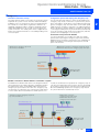
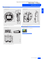
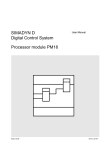
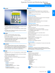
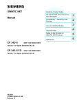
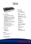
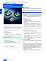
Operator Control and Monitoring Devices
Mobile Panels - 170 Series
SIMATIC Mobile Panel 170
■ Overview
■ Area of application
SIMATIC Mobile Panels are suitable for industrial applications in
all sectors. They can be used wherever mobile, on-site operation
of machines and plants is required: for example with larger production plants, complex or encapsulated machines, long transfer or production lines, or with conveying technology.
2
■ Design
• Mobile operator panel for direct operation of machines and
plants from any location
• Provides an optimum view of the workpiece or the process and,
at the same time, direct access and view of the operator unit
• Flexible use due to simple reconnection during operation
• Pixel graphics 5.7" color STN Touch Screen (analog/resistive),
16 colors
• 14 freely-configurable and freely-inscribable function keys
(8 with LEDs)
• Two 3-level enabling keys;
Optional versions with:
- STOP keys
- STOP keys, handwheel, key switches and illuminated pushbutton units
• Connection to the PLC and power supply is via the connection
box and connecting cable
■ Benefits
• Hot swapping during normal operation without interruption of
the emergency stop circuit (with junction box Plus) and without
causing any bus errors
• Fast, accurate set up and positioning
• Reliable operation with well-proven safety system concept
(Safety Category 3 to EN 954-1)
• Ergonomic and compact with low weight (approx. 1.3 kg)
• Rugged for industrial use
• Can be used worldwide:
- 21 languages can be configured
(including Asiatic and Cyrillic character sets)
- Up to 5 languages are selectable online
• Ergonomic and compact with various holding and gripping
positions (suitable for right-handed and left-handed persons)
• Pixel graphics 5.7" color STN Touch Screen (analog/resistive)
• 14 freely-configurable and freely-inscribable function keys
(8 with LEDs)
• The product is resistant to various oils, greases and standard
detergents
• Two 3-level enabling keys
• Optional product versions with
- STOP button or
- STOP button, handwheel, key switch and illuminated pushbutton
The STOP button is secured with a protective collar.
If the STOP button is looped into the emergency stop circuit,
it will have the functionality of an emergency stop pushbutton.
• Extremely resistant to shock thanks to the double wall construction and the round housing shape
(they will survive a fall from a height of 1.5 m without any damage)
• Dust-tight and splashproof housing to the IP 65 degree of protection
• Integrated, serial, MPI and PROFIBUS interface
(up to 12 Mbit/s)
• Slot for one Compact Flash card (CF card)
• Connection to the control via the reliable and rugged junction
box to the IP 65 degree of protection:
- Junction box Basic: allows the STOP button to be integrated
into the safety circuit
- Junction box Plus: allows the STOP button to be integrated
into the safety circuit
The emergency stop circuit always remains closed irrespective of whether the mobile panel is connected or not. Monitoring of the STOP button is possible.
Proven safety concept
The two enable keys (to EN 60204-1) with three switching steps
each, guarantee the protection of man and machine in critical
situations. They are integrated in the rear handle.
The STOP button (to EN 60204-1) is hard-wired and latches positively when operated. It can be looped into the emergency stop
circuit of a monitored system in which case it has the functionality of an emergency stop pushbutton, but it differs with respect
to its gray color. There is therefore no danger of confusion with
an emergency stop device. This is particularly important if the
mobile control unit is not connected to the machine. SIMATIC
Mobile Panels make it possible to provide safety functions at any
point of a machine or system.
STOP and enabling switches are designed with dual circuits
according to the safety directives, and meet the requirements of
safety category 3 to EN 954-1.
2/16
Siemens ST 80 · 2003
Operator Control and Monitoring Devices
Mobile Panels - 170 Series
SIMATIC Mobile Panel 170
■ Design (cont.)
Innovative connection concept
Configuration options with looping into emergency stop
The mobile panel is simply connected to the junction box where
required in the system or on the machine, and is immediately
available for use. The junction box can be mounted anywhere,
also outside the control cabinet. It guarantees fault-free hot
swapping, making it possible to swap the operating locations
simply and reliably if there are several connection points in a
system or machine. The mobile panel can be configured such
that the associated user-interface is selected depending on the
connection point.
The versions with STOP switches can be incorporated into the
emergency stop circuit of a machine or system via the junction
boxes. Pressing the STOP switch on the mobile panel then triggers the emergency stop. The STOP switch on the mobile panel
supplements the emergency stop device according to EN 418
which is fixed to the machine, but does not replace it. When disconnecting the mobile panel, the junction box Plus automatically
closes the emergency stop circuit, thus ensuring safe, fault-free
operation when swapping its connection point.
Connection at one point of the machine
If a junction box Basic is used, disconnecting of the mobile
panel results in opening the emergency stop circuit, and thus
triggering of the emergency stop function. This configuration is
therefore suitable for connecting the mobile panel to a fixed
point on the machine.
Wiring into the emergency stop circuit
with connection box Basic
- Mobile Panel connected – emergency stop circuit closed
- Mobile Panel disconnected – emergency stop circuit open
Q Emergency stop is triggered
Connection box
Basic
Emergency
stop circuit
Mobile Panel 170
with STOP switch
Variable connection to different stations of a machine or system
If a Mobile Panel 170 with STOP switch is used together with the
junction box Plus, it is possible to design a configuration in which
the mobile panel can be used variably and is looped into the
emergency stop circuit at the same time. The emergency stop
circuit remains closed irrespective of whether the mobile panel
is connected or disconnected. When the mobile panel is conAutomatic closing of emergency stop circuit
by connection box Plus
Connection box
[Plus 1]
nected, the STOP button is looped into the emergency stop circuit, when the STOP button is pressed, the circuit is opened and
the emergency stop function is activated. If the mobile panel is
disconnected during operation, the emergency stop circuit in
the junction box Plus is automatically closed.
- Mobile Panel connected –
emergency stop circuit closed
- Mobile Panel disconnected –
emergency stop circuit open
Connection box
[Plus n]
Emergency
stop circuit
Mobile Panel 170
with STOP switch
Siemens ST 80 · 2003
2/17
2
Operator Control and Monitoring Devices
Mobile Panels - 170 Series
SIMATIC Mobile Panel 170
■ Functions
2
• Input/output fields
for displaying and changing process parameters
• Function keys
for direct initiation of functions and actions. Up to 16 functions
can be configured simultaneously on function keys. The function keys can be used directly as PROFIBUS DP input peripherals.
• Control elements (handwheel, key switch and illuminated
pushbutton)
can be used directly as PROFIBUS DP input peripherals
• Direct control of the additional operating elements (handwheel,
key-operated switch and illuminated pushbutton) as
PROFIBUS DP input periphery (DP direct keys)
• Buttons
for direct initiation of functions and actions. Up to 16 functions
can be configured simultaneously on buttons.
• Graphics
can be used as ICONs instead of text to label function keys or
buttons. They can also be used as background displays (wallpaper).
In the configuration tool, a library is available containing extensive graphics and a wide variety of objects. All editors with an
OLE interface can be used as graphics editor (such as Paint
Shop, Designer or CorelDraw).
• Vector graphics;
basic geometric shapes (e.g. lines, circles and rectangles) can
be created direct in the configuration tool
• Fixed texts
for labeling function keys, process diagrams and process values in any character size
• Curve functions and bar charts
are used to visualize dynamic values
• Display selection from the PLC
supports operator prompting from the PLC
• Language selection;
5 online languages, 21 configuration languages incl. Asiatic
and Cyrillic character sets
• Password protection with 10 levels
• Message system;
administration of operating, fault and system messages
• Recipe management
- With additional data storage (on CF card)
- Online/offline editing on the panel
- Storing of recipe data in standard Windows format (CSV)
- External processing with standard Excel and Access tools
• Help texts
for process diagrams, messages and variables
• Mathematical functions
• Limit value monitoring
for reliable process control of inputs and outputs
• Indicator light
for machine and plant status indication
• Interval timer
for cyclic function processing
• Print;
hardcopy and messages (see "recommended printers")
• Dynamic positioning of objects and dynamic hiding and showing of objects
• Permanent window;
permanently defined screen area for outputting general information (e.g. important process variables, date and time)
2/18
Siemens ST 80 · 2003
• Simple maintenance and configuration through
- Backup and restoring the configuration, operating system,
data records and firmware on the optional CF card (Compact
Flash card)
- Backup and restoring the configuration, operating system,
data records and firmware on a PC using ProSave
- Downloading/uploading the configuration via
MPI/PROFIBUS DP/RS232 or CF Card
- Automatic transfer identification
- Individual contrast settings
- Configuration simulation directly on the configuration computer
- No batteries are necessary
Configuration
Configuring is performed using the configuration software
SIMATIC ProTool/Lite, SIMATIC ProTool or SIMATIC ProTool/Pro
Configuration Version 6.0 SP2 upwards (see configuration or
visualization software).
■ Integration
Communication with the PLC is via PROFIBUS DP at up to
12 Mbit/s, via MPI, or via the serial interface. The interfaces are
already integrated. The cable can be up to 10 meters long.
A wide range of drivers – also for third-party PLCs – are included
in the standard scope of supply. The handwheel, keyswitch and
illuminated pushbutton are directly controlled via a DP I/O (DP
direct key function).
The junction box allows the mobile panel to be connected to:
• SIMATIC S7:S7-200/-300-400
• SIMATIC WinAC Software/Slot PLC
• SIMOTION
• SIMATIC S5
• SIMATIC 505
• Third-party controllers
- Allen Bradley
- Mitsubishi
- Telemecanique
- Modicon Modbus
- GE-Fanuc
- Lucky Goldstar GLOFA
- OMRON
Note:
For further information see "System interfaces"
Operator Control and Monitoring Devices
Mobile Panels - 170 Series
SIMATIC Mobile Panel 170
■ Technical specifications
Type
Mobile Panel 170
Type
Display
• Size in inches / W x H in mm
• Resolution (pixels)
• Colors
• MTBF of backlighting (at 25°C)
STN liquid crystal display (LCD)
5.7’’ / 116 x 87
320 x 240
16 colors
Approx. 50000 hours
Dimensions
Control elements
• Type of operator control
• Programmable, freely inscribable
function keys
• Numeric/alphanumeric input
• Enabling button (EN 60204-1)
• STOP button (EN 60204-1)
• Keyswitch
• Illuminated pushbutton
• Handwheel
Expansions for operator control
of the process
• DP direct keys/LEDs (OP
keys/LEDs as I/O peripherals)
• DP direct keys/LEDs (TP buttons
as I/O peripherals)
Mobile Panel 170
• External dimensions in mm
W 245 / D 58
Weight (kg)
1.3
Certification
cULus, CE, SIBE
2
Functions
Touch and keys
14 (8 with LED)
Message system
• Operating messages
1000
• Fault messages
1000
Yes/yes
2-channel, 3-stage
Optional, 2-channel, forced
blocking, can be looped into the
emergency stop circuit
Optional, 3 switching positions
Optional
Optional
• System messages
Yes
• Message length
(lines x characters)
1 x 70
• Message buffer
Circulating buffer, 256 each, no
battery back-up
Recipes
• Records per recipe
• Entries per record
• Recipe memory
100
200
200
32 KB integrated flash, expandable
F1...F14
Process diagrams
• Text objects
• Graphics objects
100
2000 text elements
Bitmaps, icons, background
images, vector graphics
Graphs, bars, hidden buttons
4-byte or encoded
Operating system
Win CE
Memory
• Type
• Useable memory for user data
Flash / RAM
768 KB
Variables
1000
2 x RS232, 1 x RS422, 1 x RS485
max. 12 Mbit/s
1 x CF card slot
Password protection (levels)
10
Printer functions
Hardcopy, messages
Online languages
• Project languages
5
Danish, German, traditional Chinese, simplified Chinese, English,
Finnish, French, Greek, Italian,
Japanese, Korean, Dutch, Norwegian, Polish, Portuguese, Russian, Swedish, Spanish, Czech,
Turkish, Hungarian
Interfaces
• CF card slot
• Dynamic objects
- Libraries
Yes
Interface with PLC
S5, S7-200, S7-300/400, 505,
WinAC Soft-PLC/Slot-PLC
(V 3.0 upwards), SIMOTION,
Allen Bradley (DF1), Mitsubishi
(FX), Telemecanique (Uni-Telway), Modicon (Modbus),
further PLCs from other vendors
Clock
Hardware clock, unbuffered,
synchronized
Character set
Tahoma, freely scalable
Help text
Yes
Supply voltage
Via junction box
Timer
Yes
Degree of protection
IP 65
Configuration tool
Ambient conditions
• Temperature
- Operation
- Transport, storage
• Relative humidity, max.
0 °C to 40 °C
-20 °C to 60 °C
80 %
• Configuration transfer
ProTool/Lite Version 6.0 SP2
upwards, executable under Windows 98/SE/ME/NT/2000/XP Professional (must be ordered
separately)
Serial / MPI / PROFIBUS DP/
automatic transfer detection
Type
Junction box Basic:
Junction box Plus:
Ports
1 x RS232, 1 x RS422, 1 x RS485 max. 12 Mbit/s
1 x RS232, 1 x RS422, 1 x RS485 max. 12 Mbit/s
Expansions for operator control of the process
• Hot swapping
With interruption in emergency stop circuit
Without interruption in emergency stop circuit
• Monitoring of the STOP button
No
Yes
• Location identification
Yes
Yes
Housing degree of protection
IP 65
IP 65
Power supply
24 V DC
24 V DC
• External dimensions W x H x D (mm)
160 x 120 x 70
160 x 120 x 70
Weight
0.35 kg
0.4 kg
• Temperature
- Operation (vertical installation)
- Transport, storage
0 °C to +50 °C
-20 °C to +70 °C
0 °C to +50 °C
-20 °C to +70 °C
• Relative humidity, max.
85 %
85 %
Dimensions
Ambient conditions
Siemens ST 80 · 2003
2/19
Operator Control and Monitoring Devices
Mobile Panels - 170 Series
SIMATIC Mobile Panel 170
■ Ordering Data
Order No.
SIMATIC Mobile Panel 170
2
Order No.
Documentation (to be ordered separately)
• With integrated enabling button
6AV6 545-4BA16-0CX0
Manual Mobile Panel 170
• With integrated enabling button
and STOP button
6AV6 545-4BB16-0CX0
• German
6AV6 591-1DC30-0AA0
• English
6AV6 591-1DC30-0AB0
• With integrated enabling button,
STOP button, handwheel,
keyswitch and illuminated pushbutton
6AV6 545-4BC16-0CX0
• French
6AV6 591-1DC30-0AC0
• Italian
6AV6 591-1DC30-0AD0
• Spanish
6AV6 591-1DC30-0AE0
Junction box
• Basic
6AV6 574-1AE04-4AA0
Short startup guide for
Mobile Panel 170
• Plus
6AV6 574-1AE14-4AA0
• German
6AV6 591-1EC30-0AA0
• English
6AV6 591-1EC30-0AB0
Connection cable
• 5m
6XV1 440-4AH50
• French
6AV6 591-1EC30-0AC0
• 10m
6XV1 440-4AN10
• Italian
6AV6 591-1EC30-0AD0
Wall bracket for
Mobile Panel 170
6AV6 574-1AF04-4AA0
• Spanish
6AV6 591-1EC30-0AE0
Starter package Basic
6AV6 575-1AJ06-0CX0
ProTool user manual
Configuring Windows-based
Systems
• Mobile Panel 170 with integrated
enabling button
• German
6AV6 594-1MA06-1AA0
• Junction box Basic:
• English
6AV6 594-1MA06-1AB0
• Connection cable, 10m
• French
6AV6 594-1MA06-1AC0
• Wall bracket
• Italian
6AV6 594-1MA06-1AD0
• SIMATIC ProTool/Lite
• Spanish
6AV6 594-1MA06-1AE0
• Documentation CD, 5-language
(English, French, German, Italian, Spanish)
Communications manual for
Windows-based systems
• Software update service for
1 year
• German
6AV6 596-1MA06-0AA0
• English
6AV6 596-1MA06-0AB0
• French
6AV6 596-1MA06-0AC0
• Mobile Panel 170 with integrated
enabling button, STOP button,
handwheel, keyswitch and illuminated pushbutton
• Italian
6AV6 596-1MA06-0AD0
• Spanish
6AV6 596-1MA06-0AE0
• Junction box Plus
CF card, 16 MB
• Connection cable, 10m
Protective membrane
• Wall bracket
for protecting the touch front
against dirt and scratches
(pack of 10)
Starter package Plus
6AV6 575-1AJ16-0CX0
Accessories for reordering
• SIMATIC ProTool/Lite
6AV6 574-2AC00-2AA0
6AV6 574-1AD04-4AA0
• Documentation CD, 5-language
(English, French, German, Italian, Spanish)
Protective envelopes
for labeling strips (pack of 5)
6AV6 574-1AB04-4AA0
• Software update service for
1 year
Service package
6AV6 574-1AA04-4AA0
Comprising:
Configuration
with SIMATIC ProTool and
SIMATIC ProTool/Pro
• Blanking plug for cable inlet
see Section 4
• 2 x Pg screwed cable gland for
junction box
• 1 set of screws for junction box
cover
• 2 x terminal box (12-pole)
2/20
Siemens ST 80 · 2003
Operator Control and Monitoring Devices
Mobile Panels - 170 Series
SIMATIC Mobile Panel 170
■ Dimension drawings
Dimensions in mm
Dimensions in mm
123.9
18
61.3
SIMATIC Mobile Panel front and side view
100.7
8o
2
G_ST80_XX_00047
G_ST80_XX_00046
245
225.2
8o
121.7
92.3
2
24.6
o
7.8
Wall mounting for SIMATIC Mobile Panel
■ Further Information
Dimensions in mm
For further information, visit our website at
62.7
43
10
140
http://www.siemens.com/mobile-panels
G_ST80_XX_00045
110
120
142 ± 2
160
150
Connection box for SIMATIC Mobile Panel
Siemens ST 80 · 2003
2/21