1
UniMod GSM-4
Modem
User Manual
E109211215063
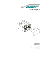
Bär Industrie-Elektronik GmbH
Siemensstr. 3
D-90766 Fürth
Germany
Phone : +49 911 970590
Fax: +49 911 9705950
Internet: www.baer-gmbh.com
UniMod GSM-4
COPYRIGHT
Copyright © 2015
BÄR Industrie-Elektronik GmbH.
All rights, including those originating from translation, (re)-printing and copying of this document
or parts thereof are reserved. No part of this manual may be copied or distributed by electronic,
mechanic, photographic or indeed any other means without prior written consent of
BÄR Industrie-Elektronik GmbH. All names of products or companies contained in this document may be trademarks or trade names of their respective owners.
Note
Based on its policies,
BÄR Industrie-Elektronik GmbH develops and improves their
products on an ongoing basis. In consequence,
BÄR Industrie-Elektronik GmbH
preserve the right to modify and improve the software product described in this document.
Specifications and other information contained in this document can change without prior notice.
This document does not cover all functions in all possible detail or variations that may be encountered during installation, maintenance and usage of the software.
Under no circumstances whatsoever will
BÄR Industrie-Elektronik GmbH accept
any liability for mistakes in this document or for any sub sequential damage arising from installation or usage of the software.
BÄR Industrie-Elektronik GmbH preserves the right to modify or withdraw this
document at any time without prior announcement.
BÄR Industrie-Elektronik GmbH does not accept any responsibility or liability for the
installation, usage, maintenance or support of third party products.
Printed in Germany
2
UniMod GSM-4
Table of Contents
Page
1
General ............................................................................................................................. 5
1.1
Requirements ........................................................................................................... 5
2
Safety Precautions for the User ...................................................................................... 6
3
Power Supply Unit ........................................................................................................... 7
4
Interfaces.......................................................................................................................... 8
5
Display............................................................................................................................ 10
6
Installation Hints ............................................................................................................ 11
7
Programming the Modem .............................................................................................. 12
7.1
7.2
8
Testing the Connection ........................................................................................... 18
Parity Error (7E1) .................................................................................................... 18
Additional Functions ..................................................................................................... 19
8.1
8.2
8.3
8.4
8.5
8.6
8.7
8.8
8.9
8.10
8.11
Reset ...................................................................................................................... 19
Signal Quality ......................................................................................................... 20
SMS Function ......................................................................................................... 21
Automatic Baud Rate Adaption ............................................................................... 22
Temporary Baud Rate Switching ............................................................................ 25
GPRS: More PLMNs............................................................................................... 26
GPRS: Fixed IP Address ........................................................................................ 27
GPRS: Dynamically Timeout .................................................................................. 27
CSD + GPRS Mode ................................................................................................ 27
GPRS: Test Mode .................................................................................................. 28
Firmware Update (Option) ...................................................................................... 28
9
Technical Data ............................................................................................................... 30
10
Inserting the Interface Modules .................................................................................... 32
11
Terminal Block ............................................................................................................... 33
12
Dimensions .................................................................................................................... 34
3
UniMod GSM-4
4
UniMod GSM-4
1
General
The world-wide GSM radio networks (GSM = Global System for Mobile
communication) provide besides digital voice communication the possibility
to transmit data. In this operation mode it is possible to send fax, data
(CSD: Circuit Switched Data connection), GPRS: General Packet Radio
Service) and short messages (SMS). The universal radio modem UniMod
GSM-4 is supposed for remote inquiry of measurement data of any kind,
especially however for telecounting applications.
The UniMod GSM-4 supports in the operation mode GPRS the meter data
communication according to DIN 43863-4 (IP-Telemetry).
1.1
Requirements
The UniMod GSM-4 can be used in any EGSM 850/900/1800/1900 MHz
network with an arbitrary number of providers. It requires however the infrastructure for operating mobile stations with 2 Watt (Class 4; 850/900
MHz) or 1 Watt (Class 1; 1800/1900 MHz) transmission power. The modem
supports an interface for 3V Mini-SIM-Cards. For communication a MiniSIM-Card with call number for 9600 Baud transmission is needed.
For the UniMod GSM-4 communication modules produced by internationally renowned companies are used. These companies update their software packages regularly and add or change features. The software
releases are continuously checked by the development department, but no
responsibility for this software releases can be taken over except of warranty granted by the module producer.
5
UniMod GSM-4
2
Safety Precautions for the User
Aircraft safety
Cellular engines can interfere with an aircraft’s navigation system and its
cellular network. The use of UniMod GSM-4 on board aircraft is forbidden
by law. Failure to comply with this prohibition may lead to temporary suspension or permanent cancellation of cellular engine services for the person who infringes this prohibition and/or to legal action against said person.
Environments with explosive substances
a) Users are advised not to use the device in automotive service stations.
b) Users are reminded of the necessity to comply with restrictions regarding
the use of radio devices in fuel depots, chemicals plants and locations
where explosives are ignited.
Non-ionising radiation
As is the case with other mobile radio transmitters, operating personnel are
advised to use the device in the normal operating position only in order to
ensure optimum performance and safety. Avoid touching the antenna.
Personnel
Installation and repairing should be done by experienced personnel only.
Connecting to other devices
In order to connect the UniMod GSM-4 to another device please read the
device’s operation manual to obtain detailed information about safety. Don’t
connect devices, which are not approved by manufacturer.
Precautions in the event of loss/theft of the Cellular Engine and
the SIM-Card
If your UniMod GSM-4, your SIM-Card or both go missing, notify your network operator immediately in order to avoid misuse.
6
UniMod GSM-4
3
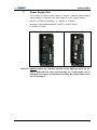
Power Supply Unit
The modem is equipped with a built-in, low-loss switched power supply,
which enables it to operate on a wide-range AC or DC supply voltage.
80VAC to 270VAC (50/60Hz) or 60VDC to 375VDC
alternative (with additional board): 10VDC to 36VDC (0,8A)
or 20VDC to 72VDC
80VAC to 270VAC / 60VDC to 375DC
10VDC to 36VDC
Attention: NEVER remove the interface modules or the SIM-Card when the device is powered! The card and especially it’s contact pads can be
damaged very easily by scratches or bending. Be careful when inserting or removing it.
7
UniMod GSM-4
4
Interfaces
Communication is possible with many standard protocols, like SCTM,
LSV1, DLMS, IEC1107 / IEC62056-21, IEC60870, M-Bus, Modbus (transparent reading).
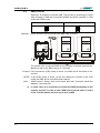
The following internal (on-board) interfaces in UniMod GSM-4 are available:
RTS
tm
CTS
tp
120R
20mA (CS, current loop) active for 4 devices max.
Can be enabled via jumpers „tp“ and „tm“. This interface supports “echo
suppression” and can be operated without load (terminal open).
RS485 (2 wires).
Using the UniModSet program the user can determine the functionality of
the RS485 interface (2-wire or disabled). Set the “120R” Jumper for activation the 120 Ohm termination (if necessary).
RS232 (RxD, TxD, DTR, DCD, GND); for service only
RTS and CTS bridged;
8
UniMod GSM-4
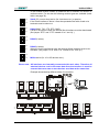
In the UniMod GSM-4 modem an additional slot is available for another interface module. For this slot the following module types are available (installation: see page 32):
RTS
tm
CTS
tp
RTS
tm
CTS
tp
20mA (CS, current loop) active (for 4 devices max.) or passive;
if the 20mA interface is active it must be operated either with a load or its
terminals must be short-cut.
RS232 (RxD, TxD, CTS, RTS, GND);
If RTS/CTS lines are used, the internal 20mA interface must be deactivated.
(Set jumper “RTS” and “CTS” instead of “tm” and “tp”.)
RTS
tm
CTS
RS485 (2 wires);
tp
RTS
tm
CTS
tp
RS485 (4 wires);
When the 4-wire interface is used, the internal 20mA interface must be deactivated. (Set jumper “RTS” and “CTS” instead of “tm” and “tp”.)
RTS
tm
CTS
M-Bus active (for 10 or 25 devices max.);
tp
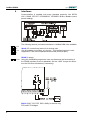
Please note: All interfaces are internally connected with each other. Therefore all
attached devices receive the same data from the interface. It must be
ensured that never two or more devices send data at the same time.
Example demonstrating different kinds of connection:
9
UniMod GSM-4
5
Display
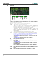
Some of LED’s display the current operating status of the modem and give information about the data transfer
10
Power signals, that the modem is supplied with power.
GSM
- permanently off: power down mode
- 500 ms on / 500 ms off: Limited Network Service: No SIM-Card
inserted or no PIN entered, or network search in progress, or ongoing user authentication, or network login in progress
- 300 ms on / 2,7 s off: IDLE mode: The mobile is logged to the
network (monitoring control channels and user interactions); no
call in progress
- permanently on: CSD call: Connection to remote party
INF
Information: 3 LEDs showing processor status and field strength.
Modem is ready for programming, data transmission and call
answering not before the leftmost INF-LED is on.
This happens
- in CSD mode (GSM dial-up connection): about 50 seconds after
“Power On”
- in GPRS mode: about 80 seconds after “Power On”
RI
lights, when the modem rings
DCD
- in CSD mode lights, when the modem has built a data link to remote station
- in GPRS mode:
IPT or BAER protocol: DCD lights, when the modem is logged to
the GPRS-Bridge
fixed IP address: DCD lights, when a remote modem has built a
data link to the UniMod GSM4;
TxD
lights, when data is transferred from modem to target device (e.g.
meter)
RxD
lights, when data is transferred from target device to modem
UniMod GSM-4
6
Installation Hints
The installation must be done in a way, that even in the case of cable break
no dangerous voltages are applied to touchable parts of the device including the antenna. This can be accomplished e.g. by using cable ties and appropriate shortening of the cables.
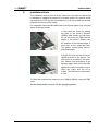
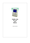
For installation insert the Mini-SIM-Card correctly and tighten it by using the
clamp of the card reader:
1) First open the clamp by shifting
the slide in the arrow’s direction
(OPEN). After release you can open
the lid and insert the SIM-Card as
shown in the picture. Please note
the position of the bevelled edge: it
must point at the upper-right side.
The golden contact pads have to
point downwards.
2) Insert the card until the lid can be
closed as shown in the picture. The
slide must be movable in this position. Please note the position of the
bevelled edge. Now move the slide
against the arrow’s direction until it
clicks into place and the lid is
locked. The SIM-Card is now ready
to use.
3) After that connect the antenna to the UniMod GSM-4 using the FME
plug.
At last (important!) connect it to the supplying power.
11
UniMod GSM-4
7
Programming the Modem
Before installing the modem it has to be programmed in order to meet the
demands. The baud rate and data format for connecting the target device
(e.g. meter) and the transmission mode and transmission rates (GSM) must
be adjusted. On delivery the following default parameters are active:
Data rate
9600 Bit/sec (if not differently mentioned)
Data format
7, Even, 1 (if not differently mentioned)
S0=1
This parameter setting determines the number of rings (here 1) before
automatic answering; for (CSD + GPRS) Mode set S0=5
&D0
This parameter determines how the modem responds when circuit 108/2
(DTR) is changed from ON to OFF during data mode. With setting 0 the
modem ignores DTR.
E0
This setting determines whether or not the modem echoes characters
received from PC during command state. (0 = no echo)
Q0 V0
Information response: numeric code
+IPR=19200
Internal baud rate: don’t change this value!
+CBST=7,0,1
The modem selects the bearer service with automatic selection of the
speed, asynchronous, non-transparent mode to be used when data calls
are originated.
This configuration allows for reading standard meters according to VDEW2
(IEC 1107 / IEC62056-21). If you want to change this parameters, you need
a PC with terminal software UniModSet/MetcomTSet. Moreover experiences with the Hayes AT modem command set are very recommended. To
establish connection between PC and modem you have to use:
A) the RS232-Service interface (standard PC port)
B) the parametering adapter with RS232 port (#9177)
C) the parametering adapter with USB port (#12683)
D) the converter (converter box or ConvBox) to adapt the interfaces
Description of the connection options:
A) Service interface: Standard RS232 cable with 9 pole plug (standard RS232,
Order No.: #4301).
12
UniMod GSM-4
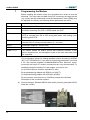
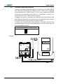
B)
The parametering adapter with RS232 port,
which can be plugged instead of an interface
module. This adapter can be ordered as accessory (Order No.: #9177).
First disconnect the modem from the supply (important!) and remove the
interface module..
Set the switch to position "GSM",
as shown in the picture.
Insert the 7 pole plug of the parametering
adapter instead of the interface module.
The notch must point in direction of the
LED’s.
Then connect the 25 pole plug (RS232) to the PC port. At last (important!)
connect it to the supplying power.
The UniMod GSM-4 can now be programmed with the software UniModSet.
13
UniMod GSM-4
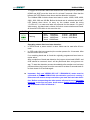
C)
The parametering adapter with
USB port (Micro-USB Type A or
B), which can be plugged instead
of an interface module. This
adapter can be ordered as accessory (Order No.: #12683).
First connect the adapter with the USB port at the PC and wait for confirmation. The new COM-Port can be find in the device manager (control panel):
USB Serial Port (COM…)
Now you have to set your terminal program to the fixed, local data rate and
data format of the UniMod. (Default values: 9600 Bit/sec, 7,E,1) Use one of
the AT commands (e.g. ATS0?, ATI, AT&V) in order to check whether the
modem answers. If you see the answer on the screen, the interface is
working correctly.
B) or C) After programming switch off the UniMod and insert the interface module
carefully again.
► Simply typing „AT“ does not result in an answer, because the modem
is by default programmed not to send messages and echoes (Parameters ATQ1 and ATE0).
14
UniMod GSM-4
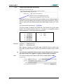
Following some examples of AT commands (the answers depend upon the
respective firmware version):
Request
at&v
Answer
ati4
at+cpin?
GE864-QUAD
+CPIN: code
OK
at+cpin=n
OK
at+clck=
"SC",0,"n"
OK
at+cops?
+COPS: 0,0,"operator"
OK
at+cops=?
+COPS:
(2,"T-Mobile D",,"26201"),
(3,"Vodafone D2",,"26202"),
(3,"E-Plus",,"26203"),
(1,"o2 - DE",,"26207"),,
(0-4),(0,2)
OK
at+cbst=
s,n,e
DTE SPEED
DTE FORMAT
GSM DATA MODE
AUTOBAUD
COMMAND ECHO
RESULT MESSAGES
VERBOSE MESSAGES
EXTENDED MESSAGES
LINE SPEED
CONSTANT DTE SPEED
FLOW CONTROL OPTIONS
ERROR CORRECTION MODE
CTS (C106) OPTIONS
DSR (C107) OPTIONS
DTR (C108) OPTIONS
DCD (C109) OPTIONS
RI (C125) OPTIONS
C108/1 OPERATION
POWER SAVING ON DTR
DEFAULT PROFILE
: 19200
: AUTO
: Not Transparent
: +IPRxxx00=NO
: E0=NO
: Q1=NO
: V1=YES
: X1=YES
: F0=autodetect
: YES
: &K3=HW bidirect.
: RLP
: &B2=OFF while disc.
: &S3=PHONE ready->ON
: &D0=ignored
: &C1=follows carrier
: \R1=OFF dur. off-hk
: &D4=NO
: +CFUN:1=NO
: &Y0=user profile 1
Description
Inquires current configuration
Requests product information
SIM-Card inquiry
(ERROR: no/faulty SIM-Card
code = SIM PIN: waiting for PIN
code = READY: PIN active)
Enter PIN, switches modem active.
e.g. AT+CPIN="1234" (if PIN is 1234)
Disable PIN lock after power off. (n = PIN)
e.g. AT+CLCK="SC",0,"1234"
Attention: First enter PIN using AT+CPIN.
Inquire bearer service. Will be shown only,
when SIM-Card is active and antenna connected.
List of available bearer services.
Choose transmission mode:
speed s=
0 - autobauding (automatic selection of the
speed, factory default)
1 - 300 bps (V.21)
2 - 1200 bps (V.22)
3 - 1200/75 bps (V.23)
4 - 2400 bps (V.22bis)
6 - 4800 bps (V.32)
7 - 9600 bps (V.32)
14 - 14400 bps (V.34)
65 - 300 bps (V.110)
66 - 1200 bps (V.110)
68 - 2400 bps (V.110 or X.31 flag stuffing)
70 - 4800 bps (V.110 or X.31 flag stuffing)
15
UniMod GSM-4
Request
Answer
at&f
ats0=n
OK
OK
ats0?
001
OK
OK
at&w
16
Description
71 - 9600 bps (V.110 or X.31 flag stuffing)
75 - 14400 bps (V110 or X.31 flag stuffing),
name n=0 for asynchronous mode,
element e=0 for transparent or e=1 for non
transparent transmission
e.g.. at+cbst=0,0,1 (for autobauding, asynchronous mode, non transparent)
Set all parameters to factory defaults.
This parameter setting determines the number
of rings (0 to 255) before automatic answering.
e.g. ats0=1 (Modem answers after first ring)
Attention: s0=0 disables automatic answering.
Returns the number of rings before automatic
answering.
Saves the current parameter setting in the
user-defined profile. This settings are active
after every resumption of power supply.
UniMod GSM-4
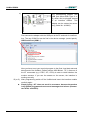
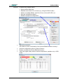
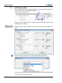
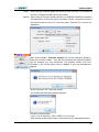
Example: Programming UniMod GSM-4
Insert the Mini-SIM-Card
Establish connection PC to modem (e.g. using the RS232 cable)
Switch on UniMod GSM-4, wait 50 to 80 sec: till first INF-LED is on
Start the UniModSet software
Read the equipment configuration:
Adjust the parameter
Hint: Mind to set the functionality of the internal RS485 interface correctly !
Write the configuration; after it: power off and on
Enable or disable the PIN via SIM-Card function
Check the signal quality and the internal temperature: possible only in CSD
mode:
17
UniMod GSM-4
7.1
Testing the Connection
For easier diagnosis of connection problems it is possible to display extended result codes for incoming call indication. In order to do this the following steps are necessary:
Activate result codes: Enter „ATQ0“, Modem reply: OK.
Activate extended result codes: „AT+CRC=1“, Modem reply: OK.
(„AT+CRC=0“ switches the extended codes off)
Call UniMod GSM-4 via data service (use appropriate telephone number).
Watch incoming call using terminal program.
Possible messages:
+CRING: REL ASYNC
incoming call has been correctly transmitted. That’s OK.
+CRING: VOICE
incoming call has been transmitted via „voice“ mode. Call rejected by modem. Remedy: set SIM-Card “Voice / Prepaid”:
+CRING: FAX
incoming call has been transmitted via „fax“ mode. Call rejected by modem.
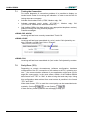
7.2
Parity Error (7E1)
Depending on certain circumstances (software configuration, hardware
configuration of the PC, connection of the modem to the PC, operating system,...) the communication software of your application might issue a message like: wrong parity. In the most cases a switch of the UniMod GSM-4
data format from "7E1" to "8N1" is able to bring fast and easy help. Using
this configuration data retrieval from most meters is possible in the format
"7E1" and "8N1".
When data format „7E1“ is used the correct parity can be transmitted automatically (Set tick
) or not (Setting
).
If there are any further questions we are happy to help you.
18
UniMod GSM-4
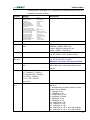
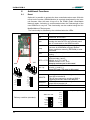
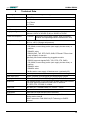
8
Additional Functions
8.1
Reset
Optional it is possible to activate the time-controlled modem-reset. With this
turned on the modem (GE864-Module) is regularly deactivated by the internal firmware. After the reset it logs on to the PLMN (Public Land Mobile
Network) again. Activating is recommended when the field-strength of the
used GSM-net is very low. This functionality can be enabled using the UniModSet/MetcomTSet program.
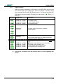
The functionality is activated by the switches below the LEDs.
X41
X40
ab
par
UE
Jumper
Function
ab
Reserved, do not use !
Closed: internal programming by AT compar
mands: the internal CPU can optionally send
the AT commands to the GE864 module.
Closed: Allow programming; changing of parameters by UniModSet program allowed.
eep
Open: parameter memory (EEPROM) is write
protected.
Must be open always, used for internal procpc2
essing.
Signals from interface module are connected
with terminals 4 and 5.
RTS + CTS RS232: 4:=CTS, 5:=RTS
RS485/4 wires: 4:=Y+, 5:=ZKeep tp and tm open in this case!
Internal 20mA interface is connected with tertm + tp
minal 4 (+) and 5 (-).
Keep RTS and CTS open in this case !
Connect either RS232 DTR signal or control
input UE to terminal 9.
The UE input serves for sending a SMS or
triggering automatic baud rate adaption.
Connect either RS232 DCD signal or control
output UA to terminal 10.
Termination for RS485: 120Ohm
UE/DTR
ee p
DTR
p c2
UA
RT S
DCD
tm
120R
CT S
tp
UA/DCD
120R
ab
par
X40: UE, UA
Delivery condition (standard):
19
eep
UE
pc2
DTR
RTS
UA
tm
DCD
CTS
120R
tp
X41: par, eep, tm, tp
UniMod GSM-4
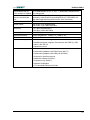
8.2
Signal Quality
When the modem operates in CSD mode (!) the INF-LEDs’ show the current field strength of the GSM signal. When the display is updated (every
three seconds) the first INF-LED flickers shortly. The second and third INFLED display the signal quality. Encoding see table below. (: LED on / :
LED off):
INF-LED
or
Signal level
-99dBm to -113dBm
-83dBm to -97dBm
-67dBm to -81dBm
-51dBm to -65dBm
Description
Bad signal quality, transmission may be disturbed.
Low signal quality;
Medium signal quality;
Good signal quality;
Undefined
(flashing)
No signal quality information available;
Check antenna
Undefined/GPRS
(flashing)
Modem logged in GPRS-Network: second and third
INF-LED flash alternately. In GPRS mode field
strength can not be displayed.
from version 81 up
After every reset: check for signal quality (once
only):
Bad signal quality: flashing every 4 seconds
Low signal quality: flashing 1Hz
Medium signal quality: flashing 2Hz
Good signal quality: flashing 3Hz
-99dBm to -113dBm
-83dBm to -97dBm
-67dBm to -81dBm
-51dBm to -65dBm
► During the connection and 60 seconds after it is the signalling disabled!
20
UniMod GSM-4
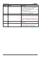
8.3
SMS Function
Optional it is possible to activate SMS. This function is monitoring of on/off
state changes of SMS input (terminals 8/GND and 9/UE), possible in CSD
mode and GPRS mode:
Interface RS232: Function DCD/DTR
SMS: Function UE/UA, Standard
UE
UE
DTR
DTR
UA
UA
DCD
DCD
Example: 20mA interface with two meters and SMS input (contact):
The modem tries to send an SMS at every change of contact (open/close).
Maximum rate is one SMS every 2 to 3 seconds.
Connect: If the connection (CSD mode) is active, the SMS will be send after a disconnect.
GPRS: If the GPRS mode is active, at the first change the modem to the CSD
mode: the SMS will be send after these change.
Note:
“SMS function” doesn’t work at the same time with “Automatic baud rate
adaption” (see page 22).
► In some cases it is neccessary to enable the SMS functionality at the
network provider. In order to test a SIM-Card it proved useful to insert
it into a mobile phone and then try to send a SMS.
21
UniMod GSM-4
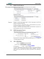
8.4
Automatic Baud Rate Adaption
Using the “Automatic Baud Rate Adaption” functionality the UniMod GSM-4
can determine automatically the baud rate that is used by the connected
meter (alternatively to “SMS Function”). This is only possible with VDEW2
meters that can be read using the IEC1107 / IEC62056-21 protocol. The
data format (7E1, 8N1 or 8E1) must be the same.
If triggered the meter is accessed using different baud rates between 300
and 19200 Bd. When the meter answers the successful baud rate is saved.
This baud rate is the restored after each power outage.
In order to use “Automatic Baud Rate Adaption” the jumpers UE and UA at
the UniMod GSM-4 must be set as shown below to use the control input UE
(terminal 8/GND and 9/UE):
Control input enabled: Function UE/UA
UE
DTR
UA
DCD
Example:
22
UniMod GSM-4
To trigger the automatic baud rate detection the control input UE (terminals
8/GND and 9/UE) must be short-cut for at least 5 seconds. After that the
leftmost INF-LED flashes three times and the detection is started.
The UniMod GSM-4 checks these baud rates in order: 19200, 9600, 4800,
2400, 1200, 600 und 300 Bd. Before the baud rate is switched the left INFLED flashes three times. At every try the modem sends the string
„/?!<CR><LF>“ to meter and waits two seconds for the answer. If it gets a
valid answer, this baud rate is chosen for further communication and saved.
All three INF-LEDs blink in this case like this:
INF-LED
Function
Baud rate
Flashing
1 time:
300 Baud
3 times: 1200 Baud
5 times: 4800 Baud
7 times: 19200 Baud
2 times: 600 Baud
4 times: 2400 Baud
6 times: 9600 Baud
Operating status after baud rate detection:
In GPRS mode a „warm restart“ is done. Meter can be read after 80 seconds.
In CSD mode (dial-up connection) the modem pauses for 10 seconds. After
that the meter can be read.
If no matching baud rate is found the originally programmed baud rate remains active.
After completion of baud rate detection the jumper at terminals 8/GND and
9/UE should be removed, else it will be performed after every power outage. To start the detection process immediately after another one has been
performed then the jumper must be removed for at least 5 seconds and after that closed for 5 seconds again.
► Important: Only one VDEW2 (IEC1107 / IEC62056-21) meter must be
connected to UniMod GSM-4 while the detection process is running !
Disconnect all meters except one before you start the baud rate detection. Before reconnecting the other meters all must be set to the same
baud rate as the first one uses. At all meters disable baud rate switching as defined in IEC1107 Mode A !
23
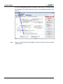
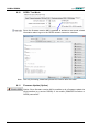
UniMod GSM-4
You can enable/disable these functionality using function “automatic baud
rate adaption (IEC 62056-21/61107 local) in the UniModSet program. See
below:
Note:
24
Function “Automatic baud rate adaption” doesn’t work at the same time with
“SMS function”
UniMod GSM-4
8.5
Temporary Baud Rate Switching
Optionally the baud rate of the electrical interface can be switched while a
request is running, without the necessity to hang up the connection. This allows to read meter with different baud rates and/or data formats (7E1, 8N1
etc.).
The command for switching is:
{[%]}=x,y*
The first number (x) defines the baud rate, the second one (y) the data
format. The modem switches after the * character is recognized without
acknowledgement. These parameters are possible:
x = 0:
1:
2:
3:
4:
5:
6:
300 Baud
600 Baud
1200 Baud
2400 Baud
4800 Baud
9600 Baud
19200 Baud
y = 0:
1:
2:
7E1
8E1
8N1
Example: {[%]}=5,0* := 9600 Baud, 7E1
{[%]}=3,1* := 2400 Baud, 8E1
After hang-up (change to OFFLINE state: DCD-LED off) the saved (old)
baud rate and data format is restored (for GPRS connection after a reset
only).
► The character sequence {[%]} has been chosen because it is quite exotic and should never appear in regular communication to meters.
Note:
25
For correct working set the data format at the UniMod GSM-4 to 8N1.
UniMod GSM-4
8.6
GPRS: More PLMNs
Since the firmware version #90 is possible to set more mobile network providers (PLMN: Public Land Mobile Network):
When the field “PLMN-Code” is empty, the UniMod GSM-4 uses the first
available mobile network.
After clicking the “More PLMN’s” button, further mobile networks can be entered:
After clicking the question mark a help window will be activated:
In this menu you find the correct PLMN-Code (Public Land Mobile Network)
for many mobile service providers.
26
UniMod GSM-4
8.7
GPRS: Fixed IP Address
Settings for fixed IP address and network port (incl. firewall):
Settings for firewall:
Examples:
Firewall = 0.0.0.0 and network mask = 0.0.0.0: connection to all IP addresses is possible (accept all);
Firewall = 192.168.1.1 and network mask = 255.255.255.255: only connection to the IP address 192.168.1.1 is possible;
Firewall = 192.168.1.0 and network mask = 255.255.255.0: connection to
the IP addresses 192.168.1.0 to 255 is possible;
8.8
GPRS: Dynamically Timeout
Dynamically time delay between CSD and GPRS log on (5, 15, 60Min, 3,
12, 24hours delay by errors).
8.9
CSD + GPRS Mode
For CSD + GPRS Mode set the number of rings to 5 (for correct GPRS disconnect). After a non-successful attempt (without CONNECT and DCDLED off) the next CSD call can now be connected in the following 5
minutes.
27
UniMod GSM-4
8.10
GPRS: Test Mode
Since the firmware version #90 is possible to activate a test mode: shows
information about log on to the GPRS network via service interface:
Note: use only for testing, deactivate please this function after the tests!
8.11
Firmware Update (Option)
Option: Since firmware version #90 is possible to do a firmware update via
local interface (e.g. service RS232) or via mobile (GSM/PSTN modem or
GPRS) connection.
28
UniMod GSM-4
Local:
When doing a firmware update via RS232 service interface it is advisable to
remove or disable the SIM-Card in the modem.
Mobile: When doing a firmware update remotely via GSM/PSTN/GPRS connection
the data format must be set to 8N1 (set option “Read”, see picture below). If
the remote modem is set to 7E1 then the option “Remote 7E1” must be enabled also:
After clicking button “Firmware Update” the current parameter setting is
read from remote modem. Then the file containing the desired firmware
can be selected (e.g. from hard disk). The program checks now if the
firmware of the remote device can be updated. If yes, this message will
appear:
A click on button “OK” starts the update.
On success the following message appears:
Duration of transmission:
Local := ca. 40 seconds; CSD / GPRS:=ca. 5 minutes
After that the modem will perform a reset and boot the uploaded firmware.
29
UniMod GSM-4
9
Technical Data
Housing:
Wall-mounted housing according to DIN 43861-2
Degree of protection:
IP52 (IEC)
Dimensions:
W = 105mm,
H = 179mm
D = 72mm
Protection class:
2
RoHS compliant:
yes
Supply voltage:
80VAC to 270VAC (50/60Hz) or 60VDC to 375VDC
Optional: 10VDC to 36VDC (0,8A) or 20VDC to 72VDC
Power consumption:
4 VA max.
Temperature range:
-40°C to +75°C (operational)
-40°C to +90°C (storage temperature)
Interfaces:
Three internal interfaces:
(depends upon supply voltage, kind of interface
module and operating status of transmission unit)
- CS (20mA, current loop) active (can supply 4 meter max.) or
passive
- RS485 2 wires
- RS232 (RxD, TxD, DTR, DCD, GND; RTS and CTS are internally bridged); for service
Optionally one extra interface by pluggable module:
- RS232 (supports signals RxD, TxD, RTS, CTS, GND)
- CS (20mA, current loop) active (can supply 4 meter max.) or
passive
- RS485 2 wires
- RS485 4 wires
- M-Bus active: can supply 10 devices max. (optionally 25)
Service interface:
RS232 (RxD, TxD, GND, DTR, DCD), RTS and CTS bridged
SMS input (UE):
12VDC (in place of DCD signal) for potential-free contact
Display:
LED’s: Power, GSM, 3 INF, RI (Ring), DCD, TxD, RxD
GSM unit:
Telit GE864-QUAD (V2) module with 3V Mini-SIM-Card interface
Fully type approved conforming with R&TTe directive
CE, GCF, FCC, PTCRB, IC, Anatel
SIM-Card:
Mini-SIM (2FF, Standard-SIM), 3V, 25mm 15mm
Approval:
CE0168 or CE0889
GSM band:
Quad-Band EGSM 850/900/1800/1900 MHz
GPRS:
Multi-slot class 10: downlink 4 timeslots, uplink 2 timeslots
Mobile station class B
M2M-Transmision: DIN 43863-4 (IP-Telemetry) or BAERProtocol
30
UniMod GSM-4
Transmission rate reUp to 9600 bit/sec (V.32 / V.110), 7 / 8 data bits, asynchronous,
mote modem to UniMod: non-transparent
Transmission rate UniMod to connected device:
300 to 19200 bit/sec (fixed baud rate)
optionally: mode B and C according IEC61107 (IEC62056-21)
with baud rate switching (300 baud to “fast” baud rate)
Data format:
7E1, 8N1, 8E1
Output power:
2W (Class 4) for 850/900 MHz
1W (Class 1) for 1800/1900 MHz
Sensitivity:
-107 dBm (850/900 MHz)
-106 dBm (1800/1900 MHz)
Antenna jack:
50 FME (m)
Software-Interface:
Hayes Standard-AT, GSM 07.07, GSM 07.05
References:
European Telecommunications Standards Institute, www.etsi.org
Extent of delivery:
- UniMod GSM-4 including interface module as ordered
- Standard antenna: magnetic foot antenna with FME (f), 0dB,
cable: 2,5m RG174
- Operation manual
Accessories:
- RS232 cable (#4301)
- Parametering adapter with RS232 port (#9177)
- Parametering adapter with USB port (#12683)
- Antenna for special purposes
- Additional interface modules
- Suspension eye (#9141)
- Software UniModSet
- AT Commands Reference Guide
31
UniMod GSM-4
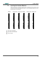
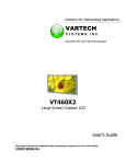
10
Inserting the Interface Modules
When inserting the interface modules their component side must be at the
left side and wired according the picture. In the following sketch the components are at the left side.
RS232
20mA active 20mA pas. RS485
M-Bus active M-Bus pas.
Pin used, connected
Pin used, not connected
Pin not used
32
UniMod GSM-4
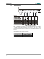
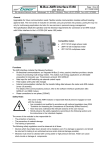
11
Terminal Block
Note: it is possible to activate the DTR input as control input (UE) for SMS.
To enable this the jumper must be set from DTR to UE (see chap. 8.3) and
the SMS functionality must be turned on using the UniModSet/MetcomTSet
program.
Optional power supply (12VDC / 24VDC):
33
Terminal
Voltage
1
+10VDC to +36VDC
2
0VDC (GND)
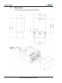
UniMod GSM-4
12
Dimensions
Wall-mounted housing according to DIN 43861-2
Subject to change without notice!