1
www.controltechniques.com
User Guide
Advanced
Position
Controller
Position Control for
Unidrive SP
Part Number: 0471-0034-03
Issue Number: 3
General Information
The manufacturer accepts no liability for any consequences resulting from inappropriate,
negligent or incorrect installation or adjustment of the optional operating parameters of
the equipment or from mismatching the variable speed drive (drive) with the motor.
The contents of this guide are believed to be correct at the time of printing. In the interests
of a commitment to a policy of continuous development and improvement, the
manufacturer reserves the right to change the specification of the product or its
performance, or the contents of this guide, without notice.
All rights reserved. No parts of this guide may be reproduced or transmitted in any form
or by any means, electrical or mechanical including photocopying, recording or by an
information storage or retrieval system, without permission in writing from the publisher.
Drive software version
This product is supplied with the latest version of user-interface and machine control
software. If this product is to be used in a new or existing system with other drives, there
may be some differences between their software and the software in this product. These
differences may cause this product to function differently. This may also apply to drives
returned from a Control Techniques Service Centre.
If there is any doubt, contact a Control Techniques Drive Centre.
Copyright
© 22 June 2004 Control Techniques Drives Ltd
Issue Code: 3
Hardware:
SM-Applications Issue 03.00
Firmware:
01.03.03
Advanced Position Controller User Guide
www.controltechniques.com
Issue Number: 3
Contents
1
Using This Manual
5
2
Safety Information
6
2.1
2.2
2.3
2.4
2.5
2.6
2.7
3
3.1
3.2
3.3
3.4
3.5
3.6
3.7
3.8
3.9
3.10
3.11
4
4.1
4.2
4.3
4.4
4.5
4.6
4.7
4.8
4.9
4.10
4.11
5
5.1
5.2
5.3
Warnings, Cautions and Notes
Electrical Safety - General Warning
System Design and Safety of Personnel
Environmental Limits
Compliance with Regulations
Motor
Adjusting Parameters
Introduction
Overview
Motion Fundamentals
Clarification of Terms
Positional Feedback/References
Positioning Modes
Resolution
Hardware
High Speed Position Capture
Task model
Performance
Interfacing
Functional Description
APC Overall Diagram
Operational Overview
Reference and Feedback Encoder Positions
Stop Reference
Position Reference
Speed Reference
CAM Reference
Digital Lock Reference
Position Loop
CTSync
APC Output Channel
APC Command Descriptions
APC Functions
DPL Commands
Conversion Functions
Advanced Position Controller User Guide
Issue Number: 3
www.controltechniques.com
6
6
6
7
7
7
7
8
9
10
10
11
12
12
14
16
16
16
17
20
20
22
24
33
33
35
36
53
57
62
64
66
66
66
127
6
6.1
6.2
6.3
6.4
6.5
6.6
7
7.1
7.2
7.3
7.4
7.5
7.6
8
8.1
8.2
8.3
9
9.1
9.2
Getting Started
Hardware Selection
Drive and Encoder setup
SM-Applications Setup for APC
User Program
Using the example code in this section
Final Performance Checks.
Program Examples
Position Reference
Digital Lock - Simple Flying Shear
CAM
Speed and Position - Homing
CTSync Master and Digital Lock
CTSync Slave and Digital Lock
Application Notes
Compensation For Overshoot With High Inertia Load
Position Loop Control on Open Loop Unidrive SP
Conversion and Word Manipulation
Migration and Software changes
Migration from V01.02.01 Firmware
APC Software Changes
134
134
136
137
138
144
144
145
145
148
152
158
163
168
172
172
175
178
181
181
182
10
Glossary of Terminology
184
11
Quick Reference
189
11.1
11.2
11.3
11.4
11.5
11.6
11.7
11.8
11.9
APC Command Reference
APC Read Parameters
SM-Applications Virtual Parameters
CTSync Command Reference
APC Definitions
SM-Applications Setup Parameters
Conversion Factors
Documentation
Overview
189
195
199
201
201
206
207
208
209
Advanced Position Controller User Guide
www.controltechniques.com
Issue Number: 3
Using This
Safety
Functional Command
Introduction
Manual Information
Description Description
1
Getting
Started
Program Application Migration Glossary of
Quick
Examples
Notes
Guide Terminology Reference
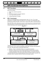
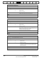
Using This Manual
This manual provides complete information on the setup and operation of the SMApplications on board Advanced Position Controller. The manual has been written
assuming that the user has the following knowledge:
•
•
•
Setup and tuning of Unidrive SP
Experience with programming SM-Applications with Sypt
Motion applications experience
The sections within this manual are in a logical order, and will progress the user from
basic safety information through to code examples. These sections are described in the
table below:
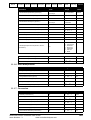
Table 1-1
Section Name
Section
Number
What the section is for
Safety
Information
2
This section describes basic drive, and drive system safety
Introduction
3
This section gives simple over view of the APC’s structure, background
information, features, and hardware, together with additional basic
information on the units used within the APC.
Functional
Description
4
This section provides a detailed description of the various functions of
the APC, like the references, what they do and how to set them up.
Additional application information is also given.
APC Command
Description
5
This section gives detailed information on each individual APC function
command, and any other applicable commands.
Getting Started
6
This section shows how to get a very simple program working using the
default settings. The user can construct a program from “building block”
code examples given in this chapter.
Program
Examples
7
This section provides several code examples, each with detailed
notation, describing the action of the code. These examples may be
copied and pasted into Sypt from the PDF version of this manual, to
form the basis of new programs.
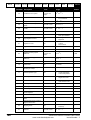
Application
Notes
8
This section provides application notes on solving common industrial
problems such as high load inertia overshoot.
Migration Guide
And Software
Changes
9
This Section Details the parameter changes introduced with SMApplications firmware version >=V01.03.00, and the new features
introduced with firmware version >V01.03.02. It also gives information
on common problems encountered when transferring code written for
previous versions of the SM-Applications firmware.
Glossary of
Terminology
10
This section gives definitions for general motion terminology, which is
also used throughout this manual.
11
This section contains short form description of all the command calls for
the APC, read parameters, aliases, diagrams, menu 90 virtual
parameters, and all the relevant SM-Applications parameters. This
section is intended for users who are familiar with the APC to refer to
whilst coding.
Quick
Reference
Text shown in Italics are cross reference links e.g. APCSetRunMode() is a link to that
commands description in the APC Command Description section. These links can be
used when the document is in PDF format.
Numbers shown in square brackets e.g. [28] are read parameter numbers, and can be
used with the command APCReadPar() to return the value of that read parameter.
Advanced Position Controller User Guide
Issue Number: 3
www.controltechniques.com
5
Functional Command
Using This
Safety
Introduction
Description Description
Manual Information
Getting
Started
Program Application Migration Glossary of
Quick
Examples
Notes
Guide Terminology Reference
2
Safety Information
2.1
Warnings, Cautions and Notes
A Warning contains information, which is essential for avoiding a safety hazard.
WARNING
A Caution contains information, which is necessary for avoiding a risk of damage to the
product or other equipment.
CAUTION
NOTE
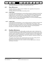
2.2
A Note contains information, which helps to ensure correct operation of the product.
Electrical Safety - General Warning
The voltages used in the drive can cause severe electrical shock and/or burns, and
could be lethal. Extreme care is necessary at all times when working with or adjacent to
the drive. Specific warnings are given at the relevant places in this User Guide.
2.3
System Design and Safety of Personnel
The drive is intended as a component for professional incorporation into complete
equipment or a system. If installed incorrectly, the drive may present a safety hazard.
The drive uses high voltages and currents, carries a high level of stored electrical
energy, and is used to control equipment which can cause injury.
Close attention is required to the electrical installation and the system design to avoid
hazards either in normal operation or in the event of equipment malfunction. System
design, installation, commissioning and maintenance must be carried out by personnel
who have the necessary training and experience. They must read this safety information
and this User Guide carefully.
The STOP and SECURE DISABLE functions of the drive do not isolate dangerous
voltages from the output of the drive or from any external option unit. The supply must
be disconnected by an approved electrical isolation device before gaining access to the
electrical connections.
With the sole exception of the SECURE DISABLE function, none of the drive
functions must be used to ensure safety of personnel, i.e. they must not be used
for safety-related functions.
Careful consideration must be given to the functions of the drive which might result in a
hazard, either through their intended behavior or through incorrect operation due to a
fault. In any application where a malfunction of the drive or its control system could lead
to or allow damage, loss or injury, a risk analysis must be carried out, and where
necessary, further measures taken to reduce the risk - for example, an over-speed
protection device in case of failure of the speed control, or a fail-safe mechanical brake
in case of loss of motor braking.
6
Advanced Position Controller User Guide
www.controltechniques.com
Issue Number: 3
Functional Command
Using This
Safety
Introduction
Description Description
Manual Information
Getting
Started
Program Application Migration Glossary of
Quick
Examples
Notes
Guide Terminology Reference
The SECURE DISABLE function has been approved1 as meeting the requirements of
EN954-1 category 3 for the prevention of unexpected starting of the drive. It may be
used in a safety-related application. The system designer is responsible for
ensuring that the complete system is safe and designed correctly according to
the relevant safety standards.
1
2.4
Independent approval by BIA has been given for sizes 1 to 3.
Environmental Limits
Instructions in the Unidrive SP User Guide regarding transport, storage, installation and
use of the drive must be complied with, including the specified environmental limits.
Drives must not be subjected to excessive physical force.
2.5
Compliance with Regulations
The installer is responsible for complying with all relevant regulations, such as national
wiring regulations, accident prevention regulations and electromagnetic compatibility
(EMC) regulations. Particular attention must be given to the cross-sectional areas of
conductors, the selection of fuses or other protection, and protective earth (ground)
connections.
The Unidrive SP User Guide contains instruction for achieving compliance with specific
EMC standards.
Within the European Union, all machinery in which this product is used must comply
with the following directives:
98/37/EC: Safety of machinery.
89/336/EEC: Electromagnetic Compatibility.
2.6
Motor
Ensure the motor is installed in accordance with the manufacturer’s recommendations.
Ensure the motor shaft is not exposed.
Standard squirrel cage induction motors are designed for single speed operation. If it is
intended to use the capability of the drive to run a motor at speeds above its designed
maximum, it is strongly recommended that the manufacturer is consulted first.
Low speeds may cause the motor to overheat because the cooling fan becomes less
effective. The motor should be fitted with a protection thermistor. If necessary, an
electric forced vent fan should be used.
The values of the motor parameters set in the drive affect the protection of the motor.
The default values in the drive should not be relied upon.
It is essential that the correct value is entered in Pr 0.46 motor rated current. This affects
the thermal protection of the motor.
2.7
Adjusting Parameters
Some parameters have a profound effect on the operation of the drive. They must not
be altered without careful consideration of the impact on the controlled system.
Measures must be taken to prevent unwanted changes due to error or tampering.
Advanced Position Controller User Guide
Issue Number: 3
www.controltechniques.com
7
Using This
Safety
Functional Command
Introduction
Manual Information
Description Description
3
Getting
Started
Program Application Migration Glossary of
Quick
Examples
Notes
Guide Terminology Reference
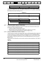
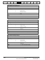
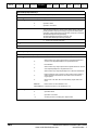
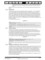
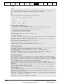
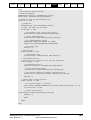
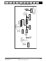
Introduction
The Advanced Position Controller is a multifunction motion kernel, which is embedded
into the SM-Applications module operating system. It has very similar features to its
predecessor on the UD70, with some enhancements relating to the user interface,
functionality and efficiency. The APC cannot be used on its own as it requires user code
for sequencing, scaling and control of the motion functionality contained within the APC
kernel.
Figure 3-1
APC Position References
CAM
Reference
Encoder
Enc
X
Y
X1
Y1
X2
Y2
X3
Y3
Xn
Yn
Index Position
Profile Generation
V
d
αa
αd
Position
Loop Gains
STOP
+
Speed
Reference
Enc
-
Speed Profile
Generation
V
Feedback
Encoder
αa
Feedback
Encoder
αd
Digital-Lock
Rigid
Lock
Non-Rigid
Lock
Locked
(EGB)
The APC with Unidrive SP, can be used in a wide range of closed loop applications, in
Servo or Closed Loop Vector modes. Rotational and linear motors are supported with a
wide range of feedback devices e.g. SinCos, Incremental Quadrature, EndAt and SSI.
The APC Controls the motion of one drive axis, and can be used to:
•
•
8
Perform independent discrete positional moves, where the motion trajectory is
produced by a profile generator, which controls acceleration, deceleration and
maximum speed. Typical applications include pushers, feeders, indexers etc.
Produce synchronised motion with respect to another axis. Typical uses include
simple following applications like Digital Lock or Electronic Gear Box (EGB), or
more complex synchronised profiles using an electronic CAM e.g. Flying Shear and
Rotary Knife etc.
Advanced Position Controller User Guide
www.controltechniques.com
Issue Number: 3
Using This
Safety
Functional Command
Introduction
Manual Information
Description Description
3.1
3.1.1
Getting
Started
Program Application Migration Glossary of
Quick
Examples
Notes
Guide Terminology Reference
Overview
Features
1. There are 5 motion function references, to meet a wide range of applications:
•
Stop
2.
3.
4.
5.
6.
7.
8.
9.
10.
•
Position
•
Speed
•
CAM
•
• Multiple interpolation
• Single shot or cyclic modes
• Recovery of CAM position after power loss
Digital Lock
• Rigid and Non-Rigid functionality
• Numerator/Denominator Ratio
Position Profile generator, which enables the user to change any of its parameters
and take immediate effect during a profile
Offset Profile generator, which enables the user to add a separate speed or position
offset to any of the APC references (except the Stop reference).
Bump-less transition when selecting references.
Wide range of encoder interfaces, absolute and incremental.
User definable position resolution (within the limitations of the encoder)
Marker pulse and Freeze Capture
Flexible and open interface for user program
At Speed and At Position flags for the Main and Offset profile generators
The ability to insert filters or other function blocks after the source counters for both
the Reference and Feedback position counters.
Advanced Position Controller User Guide
Issue Number: 3
www.controltechniques.com
9
Using This
Safety
Functional Command
Introduction
Manual Information
Description Description
3.2
Getting
Started
Program Application Migration Glossary of
Quick
Examples
Notes
Guide Terminology Reference
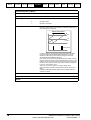
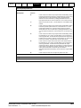
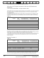
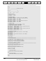
Motion Fundamentals
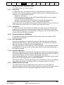
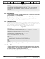
Figure 3-2 shows the relationship of the position, velocity and acceleration, when
applied to a trapezoidal velocity profile.
Figure 3-2
Target
Position
(counts)
t
Profiled
Position
(counts)
t
Velocity
(counts/sec)
Max Profile
Velocity
Velocity = Distance / Time
t
Max Profile
Velocity
Max Profile
Acceleration
Acceleration
counts/sec2
Acceleration = Velocity / Time
t
Max Profile
Acceleration
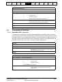
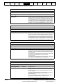
3.3
Clarification of Terms
Throughout this document the terminology shown in Table 3-1 will be used:
Table 3-1
10
Term
Single Axis
1.5 Axes
Reference
Set point for motion loop
This is the Master or the Auxiliary axis
Feedback
Main feedback to motion loop
This is the Slave or the Main drive axis
Advanced Position Controller User Guide
www.controltechniques.com
Issue Number: 3
Using This
Safety
Functional Command
Introduction
Manual Information
Description Description
•
Profile
Generator
Position
Loop Gains
V
+
d
αa
Feedback
Encoder
Motor
-
ENC
αd
1.5 axis means there is one controllable axis following another axis synchronously
in position/speed. See Figure 3-4:
Figure 3-4
Reference
Encoder
ENC
3.4
Program Application Migration Glossary of
Quick
Examples
Notes
Guide Terminology Reference
Single axis means one stand alone controllable axis, where the set point is not
directly related to another axis’ position/speed. See Figure 3-3 below:
Figure 3-3
Position
Setpoint
•
Getting
Started
CAM
or
Digital-Lock
Position
Loop Gains
+
Feedback
Encoder
Motor
-
ENC
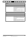
Positional Feedback/References
The reference and feedback positions can be taken from a feedback device connected
directly to the drive, a feedback device connected to a position category option module
in any drive slot, or from a user selected parameter. The latter option can be used in
conjunction with CTSync to implement a virtual master system. The update rates
associated with these options are shown in Table 3-2 below:
Table 3-2
Reference
Source
Unidrive-SP (D-Type)
Comment
Update Time
Supports Quadrature, F&D, CW/CCW, SinCos & SSI 250µs min.
SM-Universal Encoder Plus Supports Quadrature, F&D, CW/CCW, SinCos & SSI 250µs min.
SM-Encoder Plus
Supports Quadrature, F&D, CW/CCW
4ms min.
SM-Resolver
Supports Resolver only
4ms min.
User Parameter / CT-Sync
Via SM-Application port RS485
250µs min.
Feedback
Source
Unidrive-SP (D-Type)
Comment
Update Time
Supports Quadrature, F&D, CW/CCW, SinCos & SSI 250µs min.
SM-Universal Encoder Plus Supports Quadrature, F&D, CW/CCW, SinCos & SSI 250µs min.
SM-Encoder Plus
Supports Quadrature, F&D, CW/CCW
250µs min.
SM-Resolver
Supports Resolver only
250µs min.
User Parameter / CT-Sync
Via SM-Application port RS485
250µs min.
Refer to the options relevant user manual for more information.
Advanced Position Controller User Guide
Issue Number: 3
www.controltechniques.com
11
Using This
Safety
Functional Command
Introduction
Manual Information
Description Description
3.5
Getting
Started
Program Application Migration Glossary of
Quick
Examples
Notes
Guide Terminology Reference
Positioning Modes
The APC reference and feedback position counters are incremented by integrating the
encoder counts per sample. The start or reset position can be defined by one of the
following modes: -
3.5.1
Relative Mode
In this mode the reference and feedback counters are set to zero when an APC Reset is
actioned. If required an offset position can be added to the feedback counters.
Any encoder can be used in this mode.
3.5.2
Absolute Mode
In this mode the reference and the feedback counters are set to the absolute position
values read directly from the source encoder when an APC Reset is actioned. If
required an offset position can be added to the feedback counters.
This is useful when using absolute feedback devices like SSI, SinCos, EndAt, as the
absolute position is maintained at all times, even without power.
3.6
3.6.1
Resolution
The APC kernel resolution
The APC uses 32 bit signed resolution.
3.6.2
Encoder Resolution
3.6.2.1 Scaling
The reference and feedback encoder position counters can be scaled from 216 to 231
depending on the encoder used. For example, high resolution SinCos encoder can have
a maximum of 222bit resolution per turn, which can be scaled down to a minimum of 216.
When the resolution of the encoder counts per revolution is less than 216, the encoder
counts will be interpolated up to 216.
Note: The true resolution will still equal the encoder counts per revolution, though it has
been interpolated up to 216, each count will go up in large steps.
E.g. for 1024ppr encoder the counts per rev will be 4096. For one count the counter will
go up in steps of 16 (65536/4096).
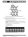
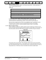
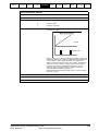
3.6.2.2 Incremental Encoder Resolution
Figure 3-5 shows how to determine the number of encoder lines, (or counts per
revolution) for a quadrature incremental encoder.
12
Advanced Position Controller User Guide
www.controltechniques.com
Issue Number: 3
Using This
Safety
Functional Command
Introduction
Manual Information
Description Description
Getting
Started
Program Application Migration Glossary of
Quick
Examples
Notes
Guide Terminology Reference
Figure 3-5
One
Encoder
Pulse
A
A
Encoder
Lines
B
B
The number of lines per revolution = 4 * encoder pulses per revolution.
3.6.2.3 SinCos Encoder Feedback Resolution.
When operating with SinCos Encoder feedback the maximum resolution is determined
from:
1. The number of sine waves of the encoder.
2. The interpolated information resolution.
The Max. Feedback Resolution per turn = Number of sine waves * Interpolated
resolution
The interpolated information resolution can vary between a maximum of 11 bits (2048)
to a minimum of 6 bits (64) with this being determined from
1. The input frequency.
2. The encoder voltage levels.
Drive encoder input Table 3-3:
Table 3-3
Feedback Signal Feedback Signal Frequency
Voltage Level
1kHz
5kHz
50kHz
100kHz
200kHz
500kHz
1.2Vdc
2048
2048
1024
1024
512
256
1.0Vdc
2048
2048
1024
512
512
128
0.8Vdc
1024
1024
1024
512
256
128
0.6Vdc
1024
1024
512
512
256
128
0.4Vdc
512
512
512
256
128
64
SM-Universal Encoder Plus Encoder input Table 3-4.
Advanced Position Controller User Guide
Issue Number: 3
www.controltechniques.com
13
Using This
Safety
Functional Command
Introduction
Manual Information
Description Description
Getting
Started
Program Application Migration Glossary of
Quick
Examples
Notes
Guide Terminology Reference
Table 3-4
Feedback Signal Feedback Signal Frequency
Voltage Level
1kHz
5kHz
50kHz
100kHz
166kHz
1.2Vdc
2048
2048
1024
1024
512
1.0Vdc
2048
2048
1024
512
512
0.8Vdc
1024
1024
1024
512
256
0.6Vdc
1024
1024
512
512
256
0.4Vdc
512
512
512
256
128
3.6.2.4 Synchronous Serial Interface (SSI) and EndAt Encoder Resolution
The resolution of this encoder is given as number of turn bits and the number of bits per
turn. For example an SSI or EndAt encoder may be described as 25bit, where 13bits are
the number of turn bits and the 12bits are for the number of counts per revolution. In this
case the counts will be interpolated up to 16bits by the drive, so each increment will be
in 16 count steps.
Please Refer to the relevant user manual for more detailed information.
NOTE
3.7
Hardware
To utilise the Advanced Position Controller the following products are used:
3.7.1
•
Unidrive SP
•
SM-Applications module or SM-Applications Lite module
SM-Applications Module
The SM-Applications module for Unidrive SP is an option module that can be fitted to
any one of the three expansion slots in the Unidrive SP and is powered from the
Unidrive SP internal power supply.
3.7.1.1 Specifications
•
High speed dedicated microprocessor
•
384kb Flash memory for user program
•
80kb user program memory
•
EIA-RS485 port offering ANSI, Modbus-RTU slave and master, and ModbusASCII slave and master protocols
•
CTNet high speed network connection offering up to 5Mbit/s data rate
•
Two high speed 24V digital inputs and outputs
•
Dual-port RAM interface for communicating with the Unidrive SP and other
option modules
Task based programming system allowing for real-time control of drive and process.
This is a general overview only. For more information refer to the SM-Applications
manual for more information.
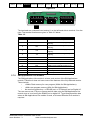
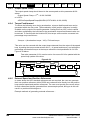
3.7.1.2 Electrical Connections
The SM-Applications module (Figure 3-6) has 2 no. 5-way and 1 no. 3-way screw
terminal blocks.
14
Advanced Position Controller User Guide
www.controltechniques.com
Issue Number: 3
Using This
Safety
Functional Command
Introduction
Manual Information
Description Description
Getting
Started
Program Application Migration Glossary of
Quick
Examples
Notes
Guide Terminology Reference
Figure 3-6
1 2 3 4 5
6 7 8
9 10 11 12 13
The terminals are numbered from terminal 1 on the left hand side to terminal 13 on the
right. The terminal functions are given in Table 3-5 below:
Table 3-5
3.7.2
Terminal
Function
Description
1
0V SC
2
/RX
EIA-RS485 Receive line (negative).
Incoming.
3
RX
EIA-RS485 Receive line (positive).
Incoming.
4
/TX
EIA-RS485 Transmit line (negative).
Outgoing.
5
TX
EIA-RS485 Transmit line (positive).
Outgoing.
0V connection for RS485 port
6
CTNet A
7
CTNet Shield
CTNet data line
8
CTNet B
9
0V
0V connection for digital I/O
10
DI0
Digital input 0 (optional Freeze input)
11
DI1
Digital input 1
12
DO0
Digital output 0
13
DO1
Digital output 1
Shield connection for CTNet
CTNet data line
SM-Applications Lite module
The SM-Applications Lite module is a lower-cost version of the SM-Applications
module. Therefore it does not have some of the features of the fully featured module.
These include:
•
<384kb Flash memory for user program (384kb for SM-Applications).
•
<80kb user program memory (80kb for SM-Applications).
•
No terminal connections - no RS485 port, no CTNet port and no Digital I/O.
The user cannot use CTSync or freeze position data using the SM-Applications Lite
module, due to it not having the RS485 port or digital I/O. To get freeze position data
when an SM-Applications Lite module is used, a Universal Encoder Plus module is
required.
Advanced Position Controller User Guide
Issue Number: 3
www.controltechniques.com
15
Using This
Safety
Functional Command
Introduction
Manual Information
Description Description
3.8
3.8.1
Getting
Started
Program Application Migration Glossary of
Quick
Examples
Notes
Guide Terminology Reference
High Speed Position Capture
Marker Pulse
Discrete marker pulse capture position facilities are available for reference and
Feedback incremental encoders. With the correct interfacing hardware, (24Vdc to
RS485 converter), the marker pulse can be utilised as an additional high speed Freeze/
registration input.
3.8.2
Freeze
A high-speed freeze input can be used to capture the Drive (D-Type), encoder position,
or both the Drive encoder position and SM option position together. The Freeze
hardware can be configured to capture on a positive or negative edge in both the SMApplications and SM-Universal Encoder Plus. Table 3-6 below shows the combinations
available with the SM option used.
Table 3-6
SM-Option Module
Input & Signal Type
(DIGIN0)
T10 - 24Vdc
SM-Applications
SM-Universal Encoder Plus
3.9
(PL2)
T1 - 24Vdc
T8/T9 - RS485
Captured Positions
Drive (D-Type) Position
SM-Encoder Plus
SM-Resolver
Drive (D-Type) Position
SM-Encoder Plus
SM-Resolver SM-Universal
Encoder Plus
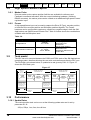
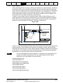
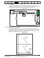
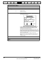
Task model
The APC kernel is executed between the POS0 and POS1 tasks of the SM-Applications
operating system, therefore allowing the user write code before and after the APC runs.
The POS task cycle shown below, is updated at a rate given by Pr81.12. Figure 3-7
shows the POS task cycle.
Figure 3-7
90µs offs et
between L2
cycle and
POS Tas k
POS1
T ask
(Use r Code )
Update Time set by
Parameter 81.12
POS0
T ask
(Use r Code )
APC
Kernel
Update s ource
integrated encoder
pos itions
Update Time set by
Parameter 81.12
POS1
T ask
POS0
T ask
(Use r Code )
(Use r Code )
Source encoder
pos itions are updated
within 90m s , in tim e
for the s tart of the next
POS tas k cycle
Source encoder
pos itions are updated
within 90µs , in tim e
for the s tart of the next
POS tas k cycle
90µs
90µs
250µs L2
Cycle
3.10
APC
Kernel
Update s ource
integrated encoder
pos itions
POS1
T ask
(Use r Code )
Source encoder
pos itions are updated
within 90m s , in tim e
for the s tart of the next
POS tas k cycle
250µs L2
Cycle
90µs offs et
between L2
cycle and
POS Tas k
Performance
3.10.1 Update Rates
The motion/position task can be runn at the following update rates and is set by
parameter 81.12:
250µs, 500µs, 1ms, 2ms, 4ms & 8ms.
16
Advanced Position Controller User Guide
www.controltechniques.com
Issue Number: 3
Using This
Safety
Functional Command
Introduction
Manual Information
Description Description
Getting
Started
Program Application Migration Glossary of
Quick
Examples
Notes
Guide Terminology Reference
To run the APC effectively and reliability with user code it is recommended to set the
update rate no faster than 500µs. Some functions will run at 250µs, but there will be
limited resources available for user code, and for CTNet to run.
The I/O on the Drive and SM-Applications module can be read at either 250µs or the
POS task update rate from the following parameters:
•
Virtual Parameter 91.16 for the Drive I/O
Parameter 86.01 to 86.04 for the SM Applications I/O.
If the Drive I/O is read from the Drive I/O parameters, parameters 8.01 to 8.06
and 8.09, the update rate is only 4ms.
NOTE
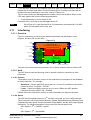
3.11
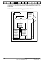
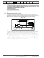
Interfacing
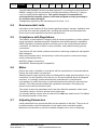
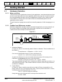
3.11.1 Overview
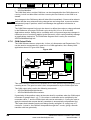
Figure 3-8 shows an overview of the interfacing between the SM-Options, user
program, Unidrive SP, and the APC.
Figure 3-8
Digital
I/O
Sypt User Program
(Sequencing, Scaling, Maths, etc)
Communications
CTSync
Freeze I/P
SM-Applications Module
Digital
I/O
APC Kernel
Analogue I/O
Position
Feedback
Other
SM-Options
Fitted
Unidrive-SP
(I/O & Parameters)
Communications
CTSync Freeze I/P
Digital
I/O
Analogue I/O
Serial
Position
Feedback Communications
The user code can access any parameter, I/O or Option module used on Unidrive SP.
3.11.2 Units
The APC Kernel uses the following units to maintain maximum resolution of each
parameter:
3.11.2.1 Position
The position is set in Encoder counts, so the resolution will correspond to set feedback
encoder resolution. For example:
•
•
Rotational - If there are 65536 counts per turn, to move 5 revolutions, the position
reference will be 5 x 65536 = 327680.
Linear - If there are 2048 counts per mm, to move 100mm the APC position
reference has to be 2048 x 100 = 204800.
Please refer to the Resolution section for more information on setpoint resolution.
3.11.2.2 Speed
The APC internal speed units are in 232 encoder counts per rev over a 250µs sample.
These units are used for the Profile Maximum Speed, Speed Reference, Reference and
Feedback Encoder Speed, Profile Generator Output Speed, and the APC Output Speed
Reference. The following equations convert rpm into internal speed units:
APC Speed = 232 * 0.00025 * rpm/60
or
APC Speed = 232 * rpm/240000
Advanced Position Controller User Guide
Issue Number: 3
www.controltechniques.com
17
Using This
Safety
Functional Command
Introduction
Manual Information
Description Description
Getting
Started
Program Application Migration Glossary of
Quick
Examples
Notes
Guide Terminology Reference
For SM-Applications programs use the following equation:
APCSpeed%=MULDIV(1073741824, SpeedRPM%, 60000) = 230 * rpm/60000
3.11.2.3 Acceleration
The APC internal acceleration units are in 232 encoder counts per rev over 250µs /
250µs. These units are used for the Profile Acceleration rate, Profile Deceleration rate,
and the Profile Output Acceleration.
APC Acceleration rate =
APC Speed (232 encoder counts per rev over 250µs) * 250µs / Accel. Time(µs)
For SM-Applications programs use the following equation:
APCAccel%=MULDIV(APCSpeed%,250,AccelTimeMicroSec%)
3.11.2.4 Proportional Gain (Kv)
The APC internal Proportional gain units are in 0.01rads/s / rad units. If required, the
word “rad” or “rads” in the proportional gain units, can substituted for any other units like
mm or revs, as the response will still be the same.
3.11.3 User Program
The interface to the APC is not via parameters, but by a series of function calls to the
main APC kernel. In most cases the operations read from, or written, to a parameter that
is held within the kernel. None of the data held by the kernel can be saved directly into
non-volatile memory, and so the user program must provide this function. The function
calls are described later in this manual in the APC Command Descriptions section. The
Sypt Pro programming tool is required to call and configure the APC motion kernel.
User Programs can be downloaded from the Sypt Pro programming tool to the SMApplications module by the following methods:
•
•
18
RS 485, using the Unidrive SP’s RJ45 comms port on the front of the drive. A
converter from RS232 or USB, to RS485 may be required. This is the only method
which can be used to down load to an SM-Applications Lite option module.
CTNet, via the dedicated terminals on the SM-Applications module. This is the
fastest way to transfer programs. A CTNet card will be required to transfer the
program from the user PC to the SM-Application module.
Advanced Position Controller User Guide
www.controltechniques.com
Issue Number: 3
Using This
Safety
Functional Command
Introduction
Manual Information
Description Description
Getting
Started
Program Application Migration Glossary of
Quick
Examples
Notes
Guide Terminology Reference
This page is intentionally blank.
Advanced Position Controller User Guide
Issue Number: 3
www.controltechniques.com
19
20
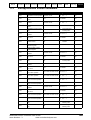
Reference Freeze Flag
22
Reference Marker Flag
Status% = APCResetRefSourceMarkerFlag()
24
30
1
1
0
0
APC Enable
Mode% =2
Status%=APCSetRunMode(Mode%)
Source Reference
Marker Position
28
Main
Reference
Position
Status% = APCResetRefSourceFreezeFlag()
29
Main Reference
Freeze Position
d/dt
CAM Function Generator
Speed Setpoint
[94]
Status% = APCSetSpeedSetPoint(Speed%)
Status% = APCSetCAMAbsResetPosInSegment(Position)
Absolute CAM Reset Position in
Segment
Status% = APCSetCAMAbsResetIndex(Index%)
Absolute CAM Reset Index
Status% = APCSelectCAMAbsoluteReset()
Status% = APCSelectCAMZeroReset()
Zero or Absolute CAM reset
Status% = APCEnableCAMSingleShot()
Status% = APCDisableCAMSingleShot()
Single Shot Mode
Status% =
APCSetCAMInterpolationMode(InterpolationMode%)
Interpolation Mode
Status% = APCSetCAMDeltaSegmentLimit(DeltaLimit%)
Delta Segment Limit
Status% = APCSetCAMSize(Size%)
Size
Status% = APCSetCAMStartIndex(StartIndex%)
Start Index Point
Numerator [62]
Denominator [63]
Fast Stop
(Ref=Fbck)
1
0
91
Stop
Position
d/dt
1
0
∆θ
Main Reference
Position
Reference Select
[100] = 4 Only
28
Absolute
Mode
Status% = APCSelectAbsoluteMode()
Status% = APCSelectRelativeMode()
Status% = APCReset()
Status% = APCResetSourcesOnDisable()
Status% = APCDoNotResetSourcesOnDisable()
RESET
3
Disable
Mode
116
2 counts per rev
encoder over 250us
Speed
Reference
32
1
48
Main Feedback
Position
A
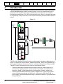
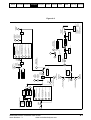
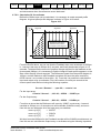
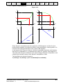
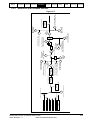
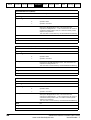
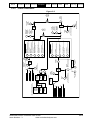
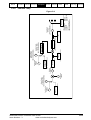
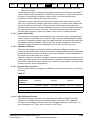
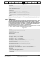
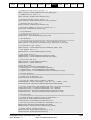
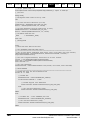
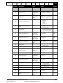
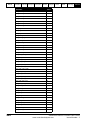
APC Overall Diagram
Stop Mode
[90]
2
3
4
4.1
Profiled Stop
(Stopping
Distance)
d/dt
STOP
POSITION
SPEED
CAM
DIGITAL-LOCK
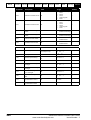
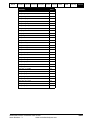
Functional Description
Status% = APCSetStopMode(Mode%)
Status% = APCSetCAMOutRatioNumerator(Ratio%)
Status% = APCSetCAMOutRatioDenominator(Ratio%)
Reference
Select [100]
Status% = APCSelectReference(Reference%)
4
Position Setpoint
[92]
CAM Current
Position in
Segment
CAM Index Pointer
Numerator [80]
Denominator [81]
83
82
Status% = APCSetDigLockRatioNumerator(Numerator%)
Status% = APCSetDigLockRatioDenominator(Denominator%)
Getting
Started
Status% = APCSetPositionSetPoint(Position%)
Status% = APCSetPositionSetPointScaled(Position%, UnitsPerRev%)
86
85
79
78
77
76
75
74
d/dt
Using This
Safety
Functional Command
Introduction
Manual Information
Description Description
Program Application Migration Glossary of
Quick
Examples
Notes
Guide Terminology Reference
Figure 4-1
Advanced Position Controller User Guide
www.controltechniques.com
Issue Number: 3
A
115
Position
Reference
Digital-Lock
Mode [61]
121
120
113
111
110
Status% = APCSetDigitalLockMode(Mode%)
Rigid Lock
[60]
Status% = APCEnableRigidLock()
Status% = APCDisableRigidLock()
System
Locked
Tolerance
Window
Speed [64]
Position [65]
Status% = APCSetDigitalLockLockingSpeed(Speed%)
Status% = APCSetDigitalLockLockingPosition(Position%)
114
|
1
0
RESET
3
Disable
Mode
118
119
Advanced Position Controller User Guide
Issue Number: 3
www.controltechniques.com
Profile
Acceleration
Reference
∆θ
1
0
130
Status% = APCSetPGain(Gain%)
Proportional
Gain Kv [131]
+
0
1
138
External Speed
Reference Select
+
Feedback Marker Flag
Status% = APCResetFbckSourceMarkerFlag()
50
1
Source Feedback
Marker Position
44
Numerator [133]
Denominator [134]
158
159
∆θ
Output Speed
Reference
157
Offset Profile
Position
Reference
Output Speed Clamp
[140]
Output
Channel Select
Status% = APCEnableOutputChannel()
Status% = APCDisableOutputChannel()
Status% = APCWriteOutputChannel(Value%)
Status% = APCSetupOutputChannel(Mode%, Menu%, Par%)
0: APC_HARD_SPEED_REF:
(Mode%, X, X)
1: APC_TORQUE_REF:
(Mode%, X, X)
2: APC_SPEED_REF:
(Mode%, X, X)
3: APC_PARAMETER:
(Mode%, Menu%, Par%)
4: APC_USER_REF:
(Mode%, Menu%, Par%)
5: APC_QUIET:
(Mode%, X, X)
Status% = APCSetOutputSpeedClamp(OutClamp%)
135
Speed% = APCGetOutputSpeed()
Speed% = APCGetOutputSpeedRpmx10()
Offset Profile
Speed
Reference
counts per rev encoder
over 250us
counts per rev encoder /
250us/250us
Offset Profile
Acceleration
Reference
Status% = APCSetOutputRatioNumerator(Numerator%)
Status% = APCSetOutputRatioDenominator(Denominator%)
+
Status% = APCSetSpeedFFwdGain()
Speed FFwd Gain [141]
1000
Status% = APCEnableExternalRefSpeed()
Status% = APCDisableExternalRefSpeed()
48
-
+
Positional
Following Error
Status% = APCSetExternalRefSpeed(Speed%)
+
158
Set to 1 when the Speed Reference [156] equals the Profile
Speed Reference [158]
At Offset Target Speed
Set to 1 when the Position Reference [155] equals the Profile
Position Reference [157]
At Offset Target Position
Status% = APCSetOffProfileMaxSpeedClamp(MaxSpeed%)
232 counts per rev encoder over 250µ s
Offset Max Profile Speed Clamp
Status% = APCSetOffProfileDecelRateScaled(DecelRate%)
milliseconds per1000 rpm
Status% = APCSetOffProfileDecelRate(DecelRate%)
232 counts per rev encoder over 250µ s / 250µ s
Deceleration
Status% = APCSetOffProfileAccelRateScaled(AccelRate%)
milliseconds per1000 rpm
P Speed
Clamp [132]
APC Enable
Mode% =2
Status%=APCSetRunMode(Mode%)
Offset Profile Generator
Acceleration
Status% = APCSetOffProfileAccelRate(AccelRate%)
232 counts per rev encoder over 250µ s / 250µ s
Status% = APCSetPGainSpeedClamp(PClamp%)
0
0
118
161
160
153
151
External Speed
Reference [139]
External Position
Reference Select
∆θ
155
Status% = APCEnableExternalRefPosition()
Status% = APCDisableExternalRefPosition()
156
Offset
Position
Reference
150
Main Feedback
Position
42
49
Main Feedback
Freeze Position
1
+
136
Status% = APCSetExternalRefPosition(Position%)
Absolute
Mode
1
+
External Position
Reference [137]
117
Profile
Position
Reference
counts per rev encoder
over 250us
Profile Speed
Reference
counts per rev encoder /
250us/250us
Status% = APCSelectAbsoluteMode()
Status% = APCSelectRelativeMode()
Status% = APCResetFbckSourceFreezeFlag()
Feedback Freeze Flag
Speed Offset [95]
Status% = APCSetSpeedOffset(Speed%)
2
0
Offset
Speed
Reference
counts per rev encoder
over 250us
102
Getting
Started
Status% = APCReset()
Status% = APCResetSourcesOnDisable()
Status% = APCDoNotResetSourcesOnDisable()
Set to 1 when the Speed Reference [116] equals the Profile
Speed Reference [118]
At Target Speed
Set to 1 when the Position Reference [115] equals the Profile
Position Reference [117]
At Target Position
Status% = APCSetProfileMaxSpeedClamp(MaxSpeed%)
232 counts per rev encoder over 250µ s
Max Profile Speed Clamp
Status% = APCSetProfileDecelRate(DecelRate%)
232 counts per rev encoder over 250µ s / 250µ s
Deceleration
Status% = APCSetProfileAccelRate(AccelRate%)
232 counts per rev encoder over 250µ s / 250µ s
Acceleration
Main Profile Generator
Status% = APCEnableProfile()
Status% = APCDisableProfile()
User Profile
Disable
CAM as
reference
Digital lock as
reference
and locked
1
Status% = APCSetPositionOffset(Position%)
Position Offset [93]
Offset Disabled
Offset Select
Status%=APCSelectOffset(Select%)
Using This
Safety
Functional Command
Introduction
Manual Information
Description Description
Program Application Migration Glossary of
Quick
Examples
Notes
Guide Terminology Reference
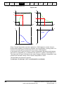
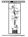
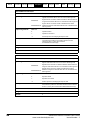
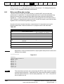
Figure 4-2
21
Using This
Safety
Functional Command
Introduction
Manual Information
Description Description
4.2
4.2.1
Getting
Started
Program Application Migration Glossary of
Quick
Examples
Notes
Guide Terminology Reference
Operational Overview
Modes of Operation
The APC can be configured to run in 3 modes:
1. Completely disabled - In this mode the APC is never called
2. Run whilst Disabled - In this mode only the encoder position counters are updated.
The encoders selected will also configure the corresponding virtual parameters in
menu 90.
3. Run - In this mode the complete APC functionality is available.
4.2.2
Reference Switching
There are 5 operating references available with the APC:
•
•
•
•
•
Stop
Position
Speed
CAM
Digital Lock
The user may switch between each of the references, with “bump-less” transfer, i.e. the
profile generator is used to ramp to the new position or speed reference, so that there
are no sudden jumps in Feedback axis position or speed, with the following exceptions:
•
•
4.2.3
Selecting the CAM reference when the Feedback axis is not at standstill
Selecting the Stop reference when Instant Stop is selected, and the Feedback Axis
is not at standstill.
Profile Generators
The Profile Generators (main and offset) determine how a change in speed or position
reference is responded to. The Profile Generators operate differently for a change in
speed reference, compared with a change in position reference. These differences are
discussed below:
•
•
For a change in speed reference, the profile generators calculate a ramp to the new
speed reference, with respect to the acceleration / deceleration rate set.
For a change in position reference, the profile generator calculates the time required
at maximum speed, with respect to the acceleration / deceleration rate set, so that
the feedback axis will ramp down and stop at, or synchronise with the new position
reference
When the main Profile generator is inactive, any change in speed or position reference
will be responded to instantly with no ramps. The maximum speed reached is still
controlled by the position loop output speed clamp.
22
Advanced Position Controller User Guide
www.controltechniques.com
Issue Number: 3
Using This
Safety
Functional Command
Introduction
Manual Information
Description Description
Getting
Started
Program Application Migration Glossary of
Quick
Examples
Notes
Guide Terminology Reference
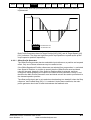
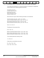
Figure shows how both profile generators acceleration and deceleration rates are
implemented:
+ Velocity
Time
- Velocity
= Deceleration rate
= Acceleration rate
Both Profile Generators have At Target Position[120] [160], and At Target Speed [121]
[161] indicators. The flags are high when profile input position or speed equals profile
output speed or position respectively.
4.2.3.1 Offset Profile Generator
The Offset Profile generator has two selectable input references; a position and a speed
offset. Only one of these references may be used at a time.
If the Offset Speed and Position references are selected from one another i.e. switched
from Speed to Position, or position to speed, then the Offset Profile accel and decel
rates will be used. However, If the Speed or Position offset is selected, and then
changed to offsets disabled, the output of the Offset Profile Generator is set to 0, and
therefore the Main Profile Generator accel and decel rate will be used to profile back to
the demand speed or position.
The offset profile decel rate is not used when decelerating to a standstill, when the Stop
reference, and Profiled Stop, [90] = 0, is selected. Under these conditions, the main
profile generator decel rate is used to decelerate the feedback axis.
Advanced Position Controller User Guide
Issue Number: 3
www.controltechniques.com
23
24
4
None
Status%=APCSetRunMode(Mode%)
Position
Alignment
[14]
42
Reset on 1st
Marker Pulse
[45]
44
Source Feedback
Marker Position
Status% = APCResetFbckSourceMarkerFlag()
Feedback Marker Flag
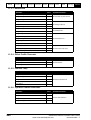
40
Source Feedback
Position
Status%=APCEnableFbckSourceMarker()
Status%=APCDisableFbckSourceMarker()
Status% = APCSetNumOfTurnsBits(n%)
n% = 1-16
APC Enable
Mode% >0
(Status%, Value%) = APCGetFeedbackStatus()
5
Status% = APCSetFeedbackPosition(Turns%, Position%, Fine%)
User Program
3
2
1
Status% = APCResetFbckSourceFreezeFlag()
Feedback Freeze Flag
Source Feedback
Freeze Position
43
1
1
41
0
Source
Feedback
Speed
46
d/dt
0
1
d/dt
-1
3
RESET
0
1
47
1
50
1
1
0
0
44
Status% = APCResetFbckSourceMarkerFlag()
Feedback Marker Flag
APC Enable
Mode% =2
[0] = 1
Status%=APCSetRunMode(Mode%)
Main Feedback
Marker Position
48
Main
Feedback
Position
Status% = APCSelectAbsoluteMode()
Status% = APCSelectRelativeMode()
Absolute
Mode
∆θ
Status% = APCReset()
Status% = APCSetPositionResetOffset(Pos%)
Status% = APCResetSourcesOnDisable()
Status% = APCDoNotResetSourcesOnDisable()
2
Offset Disable
Position Mode
Feedback
Input
51
Status% = APCSetFbckInput(Input%)
52
Source Feedback Invert
Status% = APCInvertFbckSource()
Status% = APCDoNotInvertFbckSource()
Feedback Input
Disable
Status% = APCEnableFbckInput()
0 Status% = APCDisableFbckInput()
42
Getting
Started
Option Encoder Slot 3
Option Encoder Slot 2
Option Encoder Slot 1
Drive D-Type Encoder
0
Status% = APCSetFeedbackSource(n%)
Feedback Freeze Flag
Status% = APCResetFbckSourceFreezeFlag()
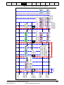
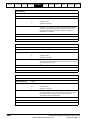
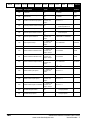
4.3
49
Main Feedback
Freeze Position
Using This
Safety
Functional Command
Introduction
Manual Information
Description Description
Program Application Migration Glossary of
Quick
Examples
Notes
Guide Terminology Reference
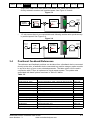
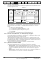
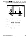
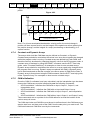
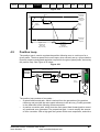
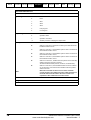
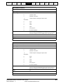
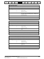
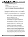
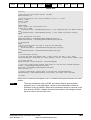
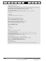
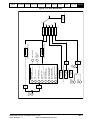
Reference and Feedback Encoder Positions
Feedback encoder position counter (Slave):
Figure 4-3
Advanced Position Controller User Guide
www.controltechniques.com
Issue Number: 3
4
Advanced Position Controller User Guide
Issue Number: 3
www.controltechniques.com
None
Status%=APCSetRunMode(Mode%)
Position
Alignment
[14]
22
1
21
Reset on 1st
Marker Pulse
[25]
24
Source Reference
Marker Position
Status% = APCResetRefSourceMarkerFlag()
Reference Marker Flag
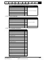
20
23
1
Source Reference
Position
Status%=APCEnableRefSourceMarker()
Status%=APCDisableRefSourceMarker()
Status% = APCSetNumOfTurnsBits(n%)
n% = 1-16
APC Enable
Mode% >0
(Status%, Value%) = APCGetReferenceStatus()
5
Status% = APCSetReferencePosition(Turns%, Position%, Fine%)
User Program
3
2
1
Status% = APCResetRefSourceFreezeFlag()
Reference Freeze Flag
Source Reference
Freeze Position
Reference Input
Disable
0
Source
Reference
Speed
26
d/dt
0
1
d/dt
-1
3
RESET
0
1
27
1
Absolute
Mode
∆θ
30
1
1
0
0
24
Status% = APCResetRefSourceMarkerFlag()
Reference Marker Flag
APC Enable
Mode% =2
[0] = 1
Status%=APCSetRunMode(Mode%)
Main Reference
Marker Position
28
Main
Reference
Position
Status% = APCSelectAbsoluteMode()
Status% = APCSelectRelativeMode()
Status% = APCReset()
Status% = APCSetPositionResetOffset(Pos%)
Status% = APCResetSourcesOnDisable()
Status% = APCDoNotResetSourcesOnDisable()
2
Offset Disable
Position Mode
Reference
Input
31
Source Reference Invert
Status% = APCInvertRefSource()
Status% = APCDoNotInvertRefSource()
Status% = APCSetRefInput(Input%)
32
Status% = APCEnableRefInput()
0 Status% = APCDisableRefInput()
22
Getting
Started
Option Encoder Slot 3
Option Encoder Slot 2
Option Encoder Slot 1
Drive D-Type Encoder
0
Status% = APCSetReferenceSource(n%)
Reference Freeze Flag
Status% = APCResetRefSourceFreezeFlag()
29
Main Reference
Freeze Position
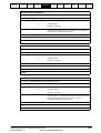
Using This
Safety
Functional Command
Introduction
Manual Information
Description Description
Program Application Migration Glossary of
Quick
Examples
Notes
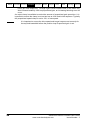
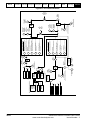
Guide Terminology Reference
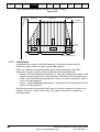
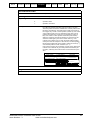
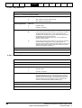
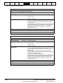
Reference encoder position counter (Master):
Figure 4-4
25
Using This
Safety
Functional Command
Introduction
Manual Information
Description Description
4.3.1
Getting
Started
Program Application Migration Glossary of
Quick
Examples
Notes
Guide Terminology Reference
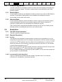
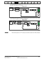
Encoder Source Update.
Using the APC the encoder source positions are updated before the POS0 task runs as
shown by Figure 4-5 below:
Figure 4-5
90µs offset
between L2
cycle and
POS Task
POS1
Task
(User Code)
Update Time set by
Parameter 81.12
POS0
Task
(User Code)
APC
Kernel
Update source
integrated encoder
positions
Update Time set by
Parameter 81.12
POS1
Task
POS0
Task
(User Code)
(User Code)
Source encoder
positions are updated
within 90ms, in time
for the start of the next
POS task cycle
Source encoder
positions are updated
within 90µs, in time
for the start of the next
POS task cycle
90µs
90µs
250µs L2
Cycle
APC
Kernel
POS1
Task
Update source
integrated encoder
positions
(User Code)
Source encoder
positions are updated
within 90ms, in time
for the start of the next
POS task cycle
250µs L2
Cycle
90µs offset
between L2
cycle and
POS Task
When using the APC in Disabled mode, where only the encoders are used, the source
encoder positions can be updated at a rate defined by parameter 81.16, this is as
follows:
0 = 250µs (every speed loop update)
1 = At the start of every POS task (Defined by 81.12)
2 = At the start of every Clock task (Defined by 81.11)
3 = Not Updated
When using the APC for best performance 81.16 should be set to 1.
4.3.2
Encoder Source Selection and Main Position Integrators
Any encoder that is connected to either the Unidrive SP or SM-Position option, can be
used as the APC Reference or Feedback source.
The SM-Applications virtual parameters (menu 90), will be setup with respect to the
APC Reference and Feedback integrated counters are incremented/decremented with
the delta position per sample of the drive encoder positions. This allows the counters to
be easily reset/preset in absolute or relative mode.
The source position can be inverted to change the direction of rotation.
4.3.3
Absolute and Relative Modes
The internal integrator counters for the Reference feedback can be used in:
•
•
26
Absolute mode - where the internal integrated position counters are preset to the
drive position counters (Plus offset feedback counters only), on an APC reset. This
is useful where absolute feedback devices are used. Definite datum position is
known.
Relative mode - where the internal counters are reset to 0 position (+Offset), on a
APC reset where it is up to the user to define the datum position.
Advanced Position Controller User Guide
www.controltechniques.com
Issue Number: 3
Using This
Safety
Functional Command
Introduction
Manual Information
Description Description
4.3.4
Getting
Started
Program Application Migration Glossary of
Quick
Examples
Notes
Guide Terminology Reference
Resetting Internal Counters
The counters can be reset with a defined offset, if required, in 2 ways
1. When the APC is disabled, the APC can be set-up to reset the counters.
By using the reset command, APCReset(). This can be used without disabling the APC.
Offsets are only added to feedback integrators.
NOTE
4.3.5
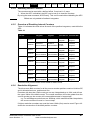
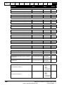
Overview of Resetting Internal Counters
Table 4-1 indicates the reset values for each of the position integrators, used within the
APC:
Table 4-1
Reference
selected
Stop
Position
Speed
CAM
Digital Lock
Mode
Reference
Integrator
Feedback
Integrator
Profile
Profile
Generator I/P Generator O/P
Relative
0
0*
Feedback
Integrator
Feedback
Integrator
Absolute
Feedback
Reference
Feedback
Source
Source Position Source Position
Position
Feedback
Integrator
Relative
0
Feedback
Integrator
Feedback
Integrator
Absolute
Reference
Feedback
Feedback
Source Position Source Position Integrator
Feedback
Integrator
Relative
0
Feedback
Integrator
Feedback
Integrator
Absolute
Reference
Feedback
Feedback
Source Position Source Position Integrator
Feedback
Integrator
Relative
0
Feedback
Integrator
Feedback
Integrator
Absolute
Reference
Feedback
Feedback
Source Position Source Position Integrator
Feedback
Integrator
Relative
0
Reference
Integrator
Feedback
Integrator
Absolute
Reference
Feedback
Reference
Source Position Source Position Integrator
Feedback
Integrator
0*
0*
0*
0*
*Denotes reset position offset will be added to these values.
4.3.6
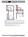
Resolution Alignment
The drive uses 48bit counters for all the source encoder positions used on Unidrive-SP,
and is allocated as turns, position and fine.
Encoders with less than 16bit counts per turn are interpolated up to 16bit, and will use
the upper 32bits of the 48bit counter. The overall resolution will not be greater than the
source encoder, as the counter will increment/decrement in larger steps.
e.g. For a 4096ppr encoder there are 16384cpr, which means that after interpolation,
the source counter will count in 4 count steps.
If higher resolution encoders are used the lower 16bits (fine) are also used. Figure 4-6
shows the construction of the 48bit position counters:
Advanced Position Controller User Guide
Issue Number: 3
www.controltechniques.com
27
Using This
Safety
Functional Command
Introduction
Manual Information
Description Description
Getting
Started
Program Application Migration Glossary of
Quick
Examples
Notes
Guide Terminology Reference
Figure 4-6
47
32
31
N u m b e r o f Tu rn s
16
15
0
C o a rs e P o s it io n
F in e P o s it io n
The APC/SM-Applications uses 32bit signed integer values, so on higher resolution
encoders e.g. SinCos, the user can define the resolution per turn required, by defining
the number of turn bits. See Figure 4-7:
Figure 4-7
47
32
31
Number of Turns
31
Coarse Position
16
APC Number of Turns
4.3.7
16
15
15
0
Fine Position
0
APC Coarse Position
A% = APCSetNumOfTurnsBits(n)
n = 1 to 16 (Default = 16)
Freeze and Marker pulse Functionality
The APC Feedback and Reference Source counters have Freeze and marker pulse
functionality. This functionality includes:
• Freeze and Marker Pulse position capture
• Marker position reset (only whilst marker position capture is not used)
• Freeze Triggering of APC References (CAM and Digital Lock)
4.3.7.1 Freeze and Marker Pulse Position Capture
The APC source counters are equipped with 2 pairs of 32bit signed position single shot
counters. Each pair of counters consists of an integrated and non-integrated position
counter, both triggered simultaneously from one trigger source, one pair by the Freeze
input (present on SM-Universal Encoder Plus and SM-Applications), and one pair by
Marker Pulse.
The command APCReadPar must be used to read the captured positions. See Table 42 below:
Table 4-2
28
Position Counter
Command
Reference Freeze Non-Integrated [21]
(Value%)=APCReadPar(21)
Reference Freeze Integrated [29]
(Value%)=APCReadPar(29)
Reference Marker Non-Integrated [23]
(Value%)=APCReadPar(23)
Reference Marker Integrated [30]
(Value%)=APCReadPar(30)
Feedback Freeze Non-Integrated [41]
(Value%)=APCReadPar(41)
Feedback Marker Integrated [49]
(Value%)=APCReadPar(49)
Feedback Marker Non-Integrated [43]
(Value%)=APCReadPar(43)
Feedback Marker Integrated [50]
(Value%)=APCReadPar(50)
Advanced Position Controller User Guide
www.controltechniques.com
Issue Number: 3
Using This
Safety
Functional Command
Introduction
Manual Information
Description Description
Getting
Started
Program Application Migration Glossary of
Quick
Examples
Notes
Guide Terminology Reference
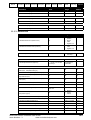
The actual position is captured within a micro second on the drive, and is passed to the
SM-Applications module on the following sample period, detailed in Table 4-3:
Table 4-3
Source
Transfer to APC Time
Freeze
Every POS task
Marker (Drive Software V01.05.00) Every 4ms
Marker (Drive Software V01.06.00) Every POS task, but the marker position capture repetition
period cannot exceed 20ms.
4.3.7.2 Freeze Position Capture
To action a Freeze capture, the following commands / virtual parameters shown in Table
4-4 have to be set:
Table 4-4
Parameter / Command
Function
APCEnableReferenceFreeze()
Reference Freeze Enable
APCEnableFeedbackFreeze()
Feedback Freeze Enable
APCResetRefSourceFreezeFlag()
Resets Reference Freeze flag
APCResetFbckSourceFreezeFlag()
Resets Feedback Freeze flag
The Freeze hardware also has to be setup, however this is dependent on which option
modules have been used for the Feedback and Reference source. Table 4-5 below
shows which parameters have to be set for the freeze hardware, for each configuration
of option modules:
Table 4-5
Configuration
Parameters to set
SM-Applications + SM-Encoder Plus
In this configuration, the Freeze signal is input
via the SM-Applications module, on Digital
Input 0 (Pin 10). Parameter 81.43 or x.43 sets
the detection type, 0 = rising edge, 1 = falling
edge. Parameter 81.42 or x.42 must be set to
1 to enable the freeze hardware.
SM-Applications + SM-Universal Encoder
Plus
In this configuration, the Freeze signal can be
input via the SM-Applications module as
above, to freeze the drive encoder position
only.
The freeze signal can also be input via the
SM-Universal Encoder Plus, as this module
can freeze the drive encoder position and its
own encoder counter position. The Freeze
sensor maybe connected to either PL2 Pin 1
(24V), or PL2 Pin 8 and 9 (RS485). Parameter
x.38 sets the Freeze signal type, 1 = 24V, 2 =
RS485, 3 = 24V + RS485 (logical OR).
Parameter x.41 sets the detection type, 0 =
rising edge, 1 = falling edge. Parameter x.40
must be set to 1 to enable the SM-Universal
Encoder Plus to freeze the main drive position.
Once a Freeze capture has taken place the freeze flags will be set, and will remain
latched on, so that further Freeze signals will not be detected until the user resets them.
To reset the Freeze flags, use the commands APCResetRefSourceFreezeFlag() and
Advanced Position Controller User Guide
Issue Number: 3
www.controltechniques.com
29
Using This
Safety
Functional Command
Introduction
Manual Information
Description Description
Getting
Started
Program Application Migration Glossary of
Quick
Examples
Notes
Guide Terminology Reference
APCResetFbckSourceFreezeFlag(). These commands reset the all of the freeze flags,
including the drive and option module flags, the virtual parameter flags in menu 90, and
the APC flags.
The Freeze position data update timing is shown in Figure 4-8 below:
Figure 4-8
340µs maximum
till freeze data
can be used
POS Task is
allways offset by
90µs from the L2
Cycle to allow
position data to be
processed
590µs maximum freeze
event period
250µs POS Task
250µs POS Task
250µs POS Task
Freeze data is
processed 90µs
into the next
250µs L2 Cycle
in time for the
next POS Task
Freeze data is
latched in
hardware at 1µs
and can occour
anywhere in a
250µs L2 cycle,
therefore
maximum pickup
time will be 250µs
as data is
processed at the
end of this cycle
250µs L2 Cycle
30
Freeze data can
be used in this
250µs POS Task
cycle, and the
Freeze flag may
be reset ready for
the next freeze
event
90µs
250µs L2 Cycle
90µs
90µs
250µs L2 Cycle
Advanced Position Controller User Guide
www.controltechniques.com
Issue Number: 3
Using This
Safety
Functional Command
Introduction
Manual Information
Description Description
Getting
Started
Program Application Migration Glossary of
Quick
Examples
Notes
Guide Terminology Reference
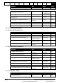
4.3.7.3 Marker Position Capture
To action a Marker position capture, the following commands / virtual parameters in
Table 4-6 below have to be set:
Table 4-6
Parameter / Command
Function
APCEnableReferenceMarker()
Reference Marker Flag Enable
APCEnableFeedbackMarker()
Feedback Marker Flag Enable
APCResetRefSourceMarkerFlag()
Resets Reference Marker flag
APCResetFbckSourceMarkerFlag()
Resets Feedback Marker flag
APCDisableRefSourceMarker()
Enables Reference Marker Position Capture
APCDisableFbckSourceMarker()
Enables Feedback Marker Position Capture
Like a Freeze position capture, after a Marker capture, the marker flags are set, and
must be reset by the commands APCResetRefSourceMarkerFlag() and
APCResetFbckSourceMarkerFlag(), before a new position may be captured.
Marker position capture can be used as a second freeze input, provided the correct
converters (24V to RS485) are used, and good EMC practices are followed.
If Marker position capture is used, then Marker position reset is not available.
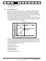
4.3.7.4 Marker Position Reset
When Feedback or Reference, Marker position reset is enabled, the relevant source
marker pulse will reset the respective source position counters within one revolution, so
that zero position and the marker pulse are aligned, as shown in Figure 4-9 below:
Figure 4-9
Marker Pulse Enabled
360°
180°
Position
Maker Pulse
If the motor has to turn less than 180° before the marker is found, then the position
counters will jump down to zero i.e. zero position turn 0. If the motor has to turn more
than 180° before the marker is found, then the position counters will jump up to zero i.e.
zero position, turn 1.The turns count is not reset to zero after a marker reset.
Advanced Position Controller User Guide
Issue Number: 3
www.controltechniques.com
31
Using This
Safety
Functional Command
Introduction
Manual Information
Description Description
Getting
Started
Program Application Migration Glossary of
Quick
Examples
Notes
Guide Terminology Reference
To action a Marker position reset, the following commands / virtual parameters shown in
Table 4-7 below have to be set:
Table 4-7
Parameter / Command
Function
APCEnableReferenceMarker()
Reference Marker Flag Enable
APCEnableFeedbackMarker()
Feedback Marker Flag Enable
APCResetRefSourceMarkerFlag()
Resets Reference Marker flag
APCResetFbckSourceMarkerFlag()
Resets Feedback Marker flag
APCEnableRefSourceMarker()
Enables Reference Marker Position Reset
APCEnableFbckSourceMarker()
Enables Feedback Marker Position Reset
If Marker position Reset is used, then Marker position capture is not available.
4.3.7.5 Freeze Triggering of APC References
The Freeze function may also be used to set the APC Reference selector to either
Digital Lock or CAM, selected by the command APCSelectActionOnFreeze(). This is
useful when an application requires that a process must be synchronised to a particular
position on the Master axis. See the Digital lock selection by Freeze and the CAM
Selection by Freeze, sections.
To action a Freeze selection, the following commands / virtual parameters in Table 4-8
below have to be set:
Table 4-8
Parameter / Command
Value
Function
APCEnableReferenceFreeze()
NA
Reference Freeze Enable
APCEnableFeedbackFreeze()
NA
Feedback Freeze Enable
APCResetRefSourceFreezeFlag()
NA
Resets Reference Freeze flag
APCResetFbckSourceFreezeFlag()
NA
Resets Feedback Freeze flag
APCSelectActionOnFreeze(Action%) Action% = 1
Action% = 2
Digital Lock Select on Freeze
CAM Select on Freeze
When a freeze signal is used to trigger the CAM or Digital Lock reference, there is no
lost position, from when the freeze was triggered to when the reference is engaged.
4.3.8
Reference and Feedback Disable
The Reference and Feedback may be disabled so that the position feedback can be
modified and re-inserted e.g. by a filter. To insert a function block:
1. The Reference or Feedback must be disabled by the commands
APCDisableRefInput() and APCDisableFbckInput() respectively.
2. The current source position must be acquired from read parameter [20] or [40] using
the APCReadPar(Parameter%) command.
3. The current source position is then fed into the function block, then the new derived
position is inserted back into the Reference or Feedback counter using the
command APCSetRefInput(Input%) or APCSetFbckInput(Input%) respectively.
If the commands APCEnableRefInput() or APCEnableFbckInput() are active then any
value written using APCSetRefInput(Input%) or APCSetFbckInput(Input%) will be
ignored, and the position counters will function as normal.
32
Advanced Position Controller User Guide
www.controltechniques.com
Issue Number: 3
Using This
Safety
Functional Command
Introduction
Manual Information
Description Description
Getting
Started
Program Application Migration Glossary of
Quick
Examples
Notes
Guide Terminology Reference
Any values written in POS0 using the commands APCSetRefInput(Input%) or
APCSetFbckInput(Input%) are used in the same POS task cycle.
4.4
Stop Reference
The Stop reference is used to stop the Feedback axis, regardless of the previous
reference, and current velocity.
The Stop reference has two different operating modes:
4.4.1
Profile Stop
In this mode, APCSetStopMode(0), when the Stop reference is selected, the axis will be
ramped from the current speed to zero. This is achieved by the stop reference being
loaded with the current position plus the stopping distance. The stopping distance is
calculated from the current velocity, and the deceleration rate set in the profile
generator, by the command APCSetProfileDecelRate(). The Final calculated stopping
position is shown by read parameter [91].
4.4.2
Instant Stop
In this mode, APCSetStopMode(1), when the Stop reference is selected, the axis will be
decelerated from the current speed to zero instantaneously with no ramps. This is
achieved by setting the stop reference to the current position, and bypassing the profile
generator. Care should be taken when using this stop mode, that the application
mechanics can withstand an instant stop without damage.
4.5
Position Reference
The Position Reference is for simple profile controlled, point to point, indexing moves.
The position setpoint may be set by APCSetPositionSetPoint, with respect to the current
resolution set by APCSetNumOfTurnsBits. The position setpoint can be set dynamically
while a profile is already in progress e.g. If the position set point is set to 100000, and
the feedback axis has travelled to 50000, then if the setpoint is changed to 200000, the
Feedback axis will stop at 200000.
The position loop reference will be profiled within the limits of the profile generator,
(accel/decel & max profile speed), for the given position setpoint.
Read parameter [92] may be used to view the current accepted position reference.
See Figure 4-10 below:
Advanced Position Controller User Guide
Issue Number: 3
www.controltechniques.com
33
Using This
Safety
Functional Command
Introduction
Manual Information
Description Description
Getting
Started
Program Application Migration Glossary of
Quick
Examples
Notes
Guide Terminology Reference
Speed
Feedback Axis
Figure 4-10
Max Speed
The area under the line
is equal to the relative
target position
Profile
acceleraton to
max speed
NOTE:
34
Traveling at max
speed to position
setpoint
Profile
deceleraton to
zero speed and
position setpoint
Time
If the Position reference is used for in an Indexing application where position change =
Current position + Index, the position reference will roll-over with the feedback once -231
to 231-1 is exceeded. This means that the user can Index in one direction infinitely,
without any unexpected position changes.
Advanced Position Controller User Guide
www.controltechniques.com
Issue Number: 3
Using This
Safety
Functional Command
Introduction
Manual Information
Description Description
4.6
Getting
Started
Program Application Migration Glossary of
Quick
Examples
Notes
Guide Terminology Reference
Speed Reference
The Speed reference may be used for jogging and homing type applications. The Speed
setpoint is set by APCSetSpeedSetPoint, in 232 counts / rev encoder over 250µs.
The position loop reference will be profiled within the limits of the profile generator,
(accel/decel & max profile speed), for the given speed setpoint. See Figure 4-11 below:
Speed
Feedback Axis
Figure 4-11
Speed
Setpoint
The area under the
line is the distance
travelled
Profile
acceleraton to
speed setpoint
Traveling at speed
setpoint
Advanced Position Controller User Guide
Issue Number: 3
www.controltechniques.com
Profile
deceleraton when
speed setpoint is
set to zero
Time
35
Using This
Safety
Functional Command
Introduction
Manual Information
Description Description
4.7
4.7.1
Getting
Started
Program Application Migration Glossary of
Quick
Examples
Notes
Guide Terminology Reference
CAM Reference
Introduction
A mechanical cam produces linear or varied motion from a continuous circular motion
i.e. one motion with respect to another. The APC CAM reference works in similar way; a
table of Feedback or slave position movements, are calculated with respect to
Reference or master position movements, forming a CAM profile table, such that when
the CAM reference is selected, the APC produces a varied Feedback axis position
reference with respect to Reference axis encoder position, with the given interpolation
type selected. See Figure 4-12 below:
Figure 4-12
Reference
Input Array
Interpolation
Array
Feedback
Output array
X1
X2
X3
|
|
|
|
|
|
Xn
I1
I2
I3
|
|
|
|
|
|
In
Y1
Y2
Y3
|
|
|
|
|
|
Yn
Reference
Encoder
E
4.7.2
(Optional)
Numerator
Denominator
Position
Reference
CAM Co-ordinates
4.7.2.1 Basics
The moves generated by the CAM reference are created from a series CAM position coordinates. These co-ordinates are arranged into Input (Reference) and Output
(Feedback) arrays. Arrays are sets of variables of the same type, arranged in order,
each variable forming an Array Element, each with a numerical reference. A typical
CAM array in DPL might look like:
InArray%[0]
= 109227
InArray%[1]
= 218454
InArray%[2]
= 54613
OutArray1%[0]
= 109227
OutArray1%[1]
= 436908
OutArray1%[2]
= 54613
The co-ordinates are entered in relative position increments, therefore the feedback
absolute position when the CAM has run one cycle, is the sum of all of the feedback coordinates in the array. See Table 4-9 below:
Table 4-9
36
Segment
Relative Position
Absolute Position
1
109227
109227
2
436908
546135
3
54613
600748
Advanced Position Controller User Guide
www.controltechniques.com
Issue Number: 3
Using This
Safety
Functional Command
Introduction
Manual Information
Description Description
Getting
Started
Program Application Migration Glossary of
Quick
Examples
Notes
Guide Terminology Reference
The CAM is a Monotonic reference i.e. increments when the reference moves forward,
and decrements when the reference moves backward.
4.7.2.2 Calculation Of Co-ordinates
Before the CAM arrays can be calculated, it is necessary to create a speed profile
diagram. A typical speed profile diagram is shown in Figure 4-13 below:
Speed
Feedback Axis
Figure 4-13
Segment1
Segment2
Segment3
200rpm
The shaded area in each
segment is equal to the
Feedback Axis position
co-ordinate for that segment
1s
2s
0.5s
Time
Reference Axis100rpm
From the Profile above, we can see that the Feedback axis must accelerate to 200rpm
in 1 second, then stay at 200rpm for 2 seconds, and finally decelerate to 0rpm in 0.5
seconds. To determine the amount of position change required for the feedback at the
given speed (200rpm), it is necessary to find the integral of each profile segment, or the
area under the plot in each segment. The Reference speed from the profile diagram is
100rpm, and the Reference and Feedback encoders will have the same resolution,
65536 counts / rev (number of turns bits = 16). From this it is possible to calculate the
Input and output array co-ordinates. First, the number of counts per second at the
chosen speed must be found using the following equation:
Counts / Second = ( rpm ⁄ 60 ) × counts / rev
For the Input array:
Counts / Second = ( 100 ⁄ 60 ) × 65536 = 109227cps
For the Output array:
Counts / Second = ( 200 ⁄ 60 ) × 65536 = 218454cps
From this we know that the Reference will move by 109227 counts every 1 second,
travelled at 100rpm, so a 2 second move will be double (218454 counts), and so on.
from this we can determine all of the Input array co-ordinates:
InArray%[0]
= 109227
InArray%[1]
= 218454
InArray%[2]
= 54613
We also know that 200rpm for the Feedback encoder will be 218454 counts/second, so
from this we can calculate the Output array co-ordinates using the following equations.
Advanced Position Controller User Guide
Issue Number: 3
www.controltechniques.com
37
Using This
Safety
Functional Command
Introduction
Manual Information
Description Description
Getting
Started
Program Application Migration Glossary of
Quick
Examples
Notes
Guide Terminology Reference
The Acceleration / Deceleration equation is (1/2 v x t, or the area of a triangle: 1/2 base
x height):
Acceleration or Deceleration period = ( cps × Time ) ⁄ 2
For the Acceleration period of 1s:
Acceleration Period = ( 218454 × 1 ) ⁄ 2 = 109227
For the Deceleration period of 0.5s
Deceleration Period = ( 218454 × 0.5 ) ⁄ 2 = 54613
The Steady State equation is: (v x t or Area of a square: base x height)
Steady State = cps × Time
For the Steady State period of 2s
Steady State = 218454 × 2 = 436908
The Output Array co-ordinates are then:
OutArray1%[0]
= 109227
OutArray1%[1]
= 436908
Out Array1%[2]
= 54613
The completed profile diagram is shown in Figure 4-14 below:
Segment1
Segment2
Segment3
436908
54613
200rpm
109227
Speed
Feedback Axis
Figure 4-14
1s
2s
0.5s
109227
218454
Time
54613
Reference Axis100rpm
For this particular speed profile, Square1 and Square2 interpolation must be used for
acceleration and deceleration, and linear used for the steady state section. The
interpolation array for the profile would look like this:
InterpolationArray%[0] = 2
InterpolationArray%[1] = 0
InterpolationArray%[2] = 3
For more information on interpolation, see the Interpolation section
38
Advanced Position Controller User Guide
www.controltechniques.com
Issue Number: 3
Using This
Safety
Functional Command
Introduction
Manual Information
Description Description
Getting
Started
Program Application Migration Glossary of
Quick
Examples
Notes
Guide Terminology Reference
If a continuous speed offset is required through the profile, then there is a second output
array which is a dedicated output offset array (OutArray2%). See Figure 4-15 below:
Segment1
Segment2
Segment3
54613
436908
200rpm
+ 50rpm offset
109227
Speed
Feedback Axis
Figure 4-15
50rpm
offset
1s
2s
109227
218454
0.5s
Time
54613
Reference Axis100rpm
Figure 4-15 above shows the previous speed profile with a 50rpm speed offset. The
position co-ordinates for the output offset array is calculated in the same way as the as
the steady state section of the profile:
For the Output array:
Counts / Second = ( 50 ⁄ 60 ) × 65536 = 54613cps
For the Steady State period of 1s (Segment1)
Steady State = 54613 × 1 = 54613
For the Steady State period of 2s (Segment2)
Steady State = 54613 × 2 = 109227
For the Steady State period of 0.5s (Segment3)
Steady State = 54613 × 0.5 = 27307
The Output Offset Array co-ordinates are then:
OutArray2%[0]
= 54613
OutArray2%[1]
= 109227
Out Array2%[2]
= 27307
Advanced Position Controller User Guide
Issue Number: 3
www.controltechniques.com
39
Using This
Safety
Functional Command
Introduction
Manual Information
Description Description
Getting
Started
Program Application Migration Glossary of
Quick
Examples
Notes
Guide Terminology Reference
The completed profile diagram is shown in Figure 4-16 below:
Segment1
Segment2
Segment3
54613
436908
200rpm
+ 50rpm offset
109227
Speed
Feedback Axis
Figure 4-16
50rpm
offset
54613
4.7.3
109227
27307
1s
2s
0.5s
109227
218454
Time
54613
Reference Axis100rpm
Interpolation
Interpolation with respect to the CAM reference, is a process of estimating the
Feedback position reference within a given CAM segment.
There are 3 different interpolation modes which may be selected for the CAM
Reference, using the command APCSetCAMInterpolationMode(Mode%):
•
•
•
Multiple - APCSetCAMInterpolationMode(-1), where the interpolation used per CAM
segment can be selected on an individual basis, defined by the interpolation array.
Linear - APCSetCAMInterpolationMode(0), where only Linear interpolation will be
used in all CAM segments.
Cosine - APCSetCAMInterpolationMode(1), where only Cosine interpolation will be
used in all CAM segments
Multiple interpolation incorporates both Linear and Cosine interpolation, together with
Square1, Square2, Cosine1 and Cosine2. All of these interpolation methods are
described below:
40
Advanced Position Controller User Guide
www.controltechniques.com
Issue Number: 3
Using This
Safety
Functional Command
Introduction
Manual Information
Description Description
Getting
Started
Program Application Migration Glossary of
Quick
Examples
Notes
Guide Terminology Reference
4.7.3.1 Linear Interpolation (0):
Figure 4-17
Y
Y
Y2
Y1
Y'
Y'
Y1
Y2
X
X1
X'
X
X2
X1
X'
X2
X
Y
dY/dX
dY/dX
X
-Y
When Linear Interpolation has been applied to a CAM segment, it will derive a steady
state velocity profile between CAM co-ordinates. It is used for steady state velocity
profiles. This means that if linear interpolation is used over the whole CAM there will be
a step change in velocity between CAM segments.
In the Upper half of Figure 4-17 above, Linear Interpolation has been used between
each set of co-ordinates (X,Y), to determine the value of Y’ position, with respect to X’.
The Lower half of Figure 4-17 above is the rate of change of linear interpolation, and
indicates the resultant velocity, when Linear Interpolation is used.
The final Slave axis velocity is equal to:
Y (velocity) = X (velocity) * ((Y co-ordinate)/(X co-ordinate))
Advanced Position Controller User Guide
Issue Number: 3
www.controltechniques.com
41
Using This
Safety
Functional Command
Introduction
Manual Information
Description Description
Getting
Started
Program Application Migration Glossary of
Quick
Examples
Notes
Guide Terminology Reference
4.7.3.2 Cosine Interpolation (1):
Figure 4-18
Y
Y
Y2
Y1
Y'
Y'
Y1
Y2
X
X1
X'
X
X2
X'
X1
X2
X
Y
dY/dX
dY/dX
X
-Y
When Cosine Interpolation has been applied to a CAM segment, it will derive a Cosine
velocity profile between CAM co-ordinates. It is used for smooth point to point position
changes.
In the Upper half of Figure 4-18 above, Cosine Interpolation has been used between
each set of co-ordinates (X,Y), to determine the value of Y’ position, with respect to X’.
The Lower half of Figure 4-18 above is the rate of change of Cosine interpolation, and
indicates the resultant velocity, when Cosine Interpolation is used.
The final Slave axis velocity is equal to:
Y (velocity) = X (velocity) * ((Y co-ordinate)/(2*X co-ordinate))
42
Advanced Position Controller User Guide
www.controltechniques.com
Issue Number: 3
Using This
Safety
Functional Command
Introduction
Manual Information
Description Description
Getting
Started
Program Application Migration Glossary of
Quick
Examples
Notes
Guide Terminology Reference
4.7.3.3 Square1 Interpolation (2):
Figure 4-19
Y
Y
Y2
Y1
Y'
Y'
Y1
Y2
X
X1
X'
X
X2
X1
X'
X2
X
Y
dY/dX
dY/dX
X
-Y
When Square1 Interpolation has been applied to a CAM segment, and the X axis is
positive and increasing, it will derive a positive, linear acceleration, velocity profile. It is
used for linear velocity acceleration over a given CAM segment.
In the Upper half of Figure 4-19 above, Square1 Interpolation has been used between
each set of co-ordinates (X,Y), to determine the value of Y’ position, with respect to X’.
The Lower half of Figure 4-19 above is the rate of change of Square1 interpolation, and
indicates the resultant velocity, when Square1 Interpolation is used.
The final Slave axis velocity is equal to:
Y (velocity) = X (velocity) * ((2*Y co-ordinate)/(X co-ordinate))
Advanced Position Controller User Guide
Issue Number: 3
www.controltechniques.com
43
Using This
Safety
Functional Command
Introduction
Manual Information
Description Description
Getting
Started
Program Application Migration Glossary of
Quick
Examples
Notes
Guide Terminology Reference
4.7.3.4 Square2 Interpolation (3):
Figure 4-20
Y
Y
Y2
Y1
Y'
Y'
Y1
Y2
X
X1
X'
X
X2
X1
X'
X2
X
Y
dY/dX
dY/dX
X
-Y
When Square2 Interpolation has been applied to a CAM segment, and the X axis is
positive and increasing, it will derive a negative, linear acceleration, velocity profile.It is
used for linear velocity deceleration over a given CAM segment.
In the Upper half of Figure 4-20 above, Square2 Interpolation has been used between
each set of co-ordinates (X,Y), to determine the value of Y’ position, with respect to X’.
The Lower half of Figure 4-20 above is the rate of change of Square1 interpolation, and
indicates the resultant velocity, when Square2 Interpolation is used.
The final Slave axis velocity is equal to:
Y (velocity) = X (velocity) * ((2*Y co-ordinate)/(X co-ordinate))
44
Advanced Position Controller User Guide
www.controltechniques.com
Issue Number: 3
Using This
Safety
Functional Command
Introduction
Manual Information
Description Description
Getting
Started
Program Application Migration Glossary of
Quick
Examples
Notes
Guide Terminology Reference
4.7.3.5 Cosine1 Interpolation (4):
Figure 4-21
Y
Y
Y2
Y1
Y'
Y'
Y1
Y2
X
X1
X'
X
X2
X1
X'
X2
X
Y
dY/dX
dY/dX
X
-Y
When Cosine1 Interpolation has been applied to a CAM segment, and the X axis is
positive and increasing, it will derive a positive, sinus acceleration, velocity profile. It is
used for sinusoidal velocity acceleration over a given CAM segment.
In the Upper half of Figure 4-21 above, Cosine1 Interpolation has been used between
each set of co-ordinates (X,Y), to determine the value of Y’ position, with respect to X’.
The Lower half of Figure 4-21 above is the rate of change of Square1 interpolation, and
indicates the resultant velocity, when Cosine1 Interpolation is used.
The final Slave axis velocity is equal to:
Y (velocity) = X (velocity) * ((2*Y co-ordinate)/(X co-ordinate))
Advanced Position Controller User Guide
Issue Number: 3
www.controltechniques.com
45
Using This
Safety
Functional Command
Introduction
Manual Information
Description Description
Getting
Started
Program Application Migration Glossary of
Quick
Examples
Notes
Guide Terminology Reference
4.7.3.6 Cosine2 Interpolation (5):
Figure 4-22
Y
Y
Y2
Y1
Y'
Y'
Y1
Y2
X
X1
X'
X
X2
X1
X'
X2
X
Y
dY/dX
dY/dX
X
-Y
When Cosine2 Interpolation has been applied to a CAM segment, and the X axis is
positive and increasing, it will derive a negative, sinus acceleration, velocity profile. It is
used for sinusoidal velocity deceleration over a given CAM segment.
In the Upper half of Figure 4-22 above, Cosine1 Interpolation has been used between
each set of co-ordinates (X,Y), to determine the value of Y’ position, with respect to X’.
The Lower half of Figure 4-22 above is the rate of change of Square1 interpolation, and
indicates the resultant velocity, when Cosine1 Interpolation is used.
The final Slave axis velocity is equal to:
Y (velocity) = X (velocity) * ((2*Y co-ordinate)/(X co-ordinate))
46
Advanced Position Controller User Guide
www.controltechniques.com
Issue Number: 3
Using This
Safety
Functional Command
Introduction
Manual Information
Description Description
Getting
Started
Program Application Migration Glossary of
Quick
Examples
Notes
Guide Terminology Reference
Figure 4-23 below shows a profile, and the type of interpolation required to perform that
profile.
Speed
Figure 4-23
V
½V
Time
Square2
(3)
Linear
(0)
Cosine
(1)
Linear
(0)
Cosine2
(5)
Linear
(0)
Cosine1
(4)
Linear
(0)
Interpolation
Required
Square1
(2)
Segment 1 Segment 2 Segment 3 Segment 4 Segment 5 Segment 6 Segment 7 Segment 8Segment 9
The offset array (Output2 array) would be used
here to provide an offset of ½V.
Note: For a linear acceleration/deceleration velocity profile, the actual change in
position will be a square function, as the integral of the speed over a time period gives
the position change, and the integral of a ramp (accelerating or decelerating), is a
square function.
4.7.4
Constant and Dynamic Arrays
The arrays which hold the CAM data may be defined as Constant, or Dynamic.
Constant arrays should be used when the values in an array do not need to be changed
whilst the program code is running. Constant arrays are placed into Flash ROM, and
therefore can only be altered by changing the array values in the DPL program code. A
constant array is declared by using the CONST command; see the SYPT user help
guide, under “Constant Data/Array” for examples on how to enter constant arrays.
Dynamic arrays should be used when the values in an array need to be changed whilst
the program code is running. Dynamic arrays are placed into RAM. A Dynamic array
has to be dimensioned so that the compiler can reserve space in RAM for the Data. A
Dynamic array is dimensioned using the DIM command; see the SYPT user help guide,
under “Dynamic Array” for examples on how to enter constant arrays.
4.7.5
CAM Initialisation
Once the CAM Co-ordinates have been calculated, and the interpolation type has been
chosen the CAM arrays must be Initialised by one the following commands:
•
•
•
•
APCCamInitialise - Initialises the CAM with an Input, Output 1, Output 2, and
Interpolation array.
APCCamInitialise1 - Initialises the CAM with an Input and Output 1 array.
APCCamInitialise2 - Initialises the CAM with an Input, Output 1, and Interpolation
array.
APCCamInitialise3 - Initialises the CAM with an Input, Output 1, and Output 2 array.
These commands act as a pointer for the CAM reference so that the location of the
various arrays is known.
The CAM start index and CAM Size must be set, to define where in the CAM arrays you
want to start from, and how much of the CAM, from the start point, you want to use. The
CAM start index and CAM Size is set by the commands:
Advanced Position Controller User Guide
Issue Number: 3
www.controltechniques.com
47
Using This
Safety
Functional Command
Introduction
Manual Information
Description Description
•
•
Getting
Started
Program Application Migration Glossary of
Quick
Examples
Notes
Guide Terminology Reference
APCSetCAMStartIndex
APCSetCAMSize
The CAM Start Index, and the CAM size, can be changed whilst the CAM reference is
running, but will not take effect until the current cycle has finished, or the CAM is restarted.
NOTE
Any changes to the CAM array data will take effect immediately. Care must be taken to
ensure that the array elements being changed are not being used, to prevent sudden
unexpected jumps in position, which could damage the application mechanics or
personnel.
The CAM Delta segment limit must also be set, to define the maximum change allowed
in the Reference source per POS task cycle, set by #81.12 or x.12 for the SMApplications module. Setting this to a suitable value, will prevent large step changes in
reference source, from being applied to the Slave axis, which could potentially damage
an applications mechanics. The CAM Delta Segment limit is set by the command
APCSetCAMDeltaSegLimit.
4.7.6
CAM Output Ratio
The CAM reference has an output ratio, in form of a Numerator and Denominator. This
can be used to compensate for a gear box in a CAM application, like a Rotary Knife
application shown in Figure 4-24 below:
Figure 4-24
7:3
Gear
Box
Rotary
Knife
E
E
CAM Output Ratio
CAM
Numerator 7
Denominator 3
Position
loop
Speed
Reference
Unidrive SP APC
This means that the CAM can be calculated at 1:1 ratio, therefore minimising any count
rounding errors. The gear box ratio is then compensated for by the CAM output ratio.
The CAM output ratio is set by the following commands:
•
•
APCSetCAMOutRatioNumerator
APCSetCAMOutRatioDenominator
If granularity of the position output at the motor shaft is a problem when the CAM output
numerator is greater than 1 e.g. 7:3, the slave co-ordinates can be multiplied by the
numerator value, 7, and the CAM output ratio can be reduced to 1:3 (using the ratio to
apply the denominator means that any remainder is automatically compensated for).
This means that instead of each count being directly multiplied i.e. a step jump of 7
counts for 1 count in, the CAM will interpolate through the 7 counts, giving a smooth
transition with low granularity.
48
Advanced Position Controller User Guide
www.controltechniques.com
Issue Number: 3
Using This
Safety
Functional Command
Introduction
Manual Information
Description Description
4.7.7
Getting
Started
Program Application Migration Glossary of
Quick
Examples
Notes
Guide Terminology Reference
Single Shot and Continuous CAM
The CAM may be run in of two modes:
4.7.7.1 Single Shot
In single shot mode, the CAM will run from the selected start co-ordinate, and will
continue until the last co-ordinate is reached, and then stop. The CAM then has to be restarted by one of the following methods:
•
•
•
•
Perform an APCReset
Disable single shot mode by using APCDisableCAMSingleShot, then re-enable
using APCEnableCAMSingleShot.
De-select, then reselect the CAM Reference using APCSelectReference
De-select, then reselect APC run mode 2 using APCSetRunMode
Single shot mode may be selected at any point whilst the CAM is running in continuous
mode, and will cause the CAM to run until the end of the current cycle.
4.7.7.2 Continuous
In Continuous mode, the CAM will run cyclically, running till the last co-ordinate, then
wrapping around to the first co-ordinate again. Continuous CAM mode is selected by
APCDisableCAMSingleShot. If the start index is changed, it will not take effect until the
current CAM cycle has been completed.
4.7.8
Zero and Absolute CAM Reset
It is possible to select within the defined CAM, where to start from, when the CAM
reference is next selected:
4.7.8.1 Zero CAM Reset
When the CAM reference is deselected, and Zero CAM reset has been selected by
APCSelectCAMZeroReset, when the CAM Reference is next selected, the CAM will
Start from the segment defined by APCSetCAMStartIndex.
The CAM Start Index, and the CAM size, APCSetCAMSize, can be changed whilst the
CAM reference is running, but will not take effect until the current cycle has finished, or
the CAM is re-started.
4.7.8.2 Absolute CAM Reset
When the CAM reference is deselected, and Absolute CAM reset has been selected by
APCSelectCAMAbsoluteReset, when the CAM Reference is next selected, the CAM will
start from the segment, and the position in the segment, defined by
APCSetCAMAbsResetIndex, and APCSetCAMAbsResetPositionInSeg, within the limits
defined by APCSetCAMStartIndex, and APCSetCAMSize.
This may be useful for absolute positioning when it is important to ensure the Feedback
axis / CAM is set to the correct position after an unforeseen power cut, or reset.
4.7.9
CAM Selection by Freeze
The CAM reference may be selected by a freeze input. This is useful when an
application requires that a process must be synchronised to a particular position on the
Reference / Master axis, like a flying shear application, shown in Figure 4-25:
Advanced Position Controller User Guide
Issue Number: 3
www.controltechniques.com
49
Using This
Safety
Functional Command
Introduction
Manual Information
Description Description
Getting
Started
Program Application Migration Glossary of
Quick
Examples
Notes
Guide Terminology Reference
Figure 4-25
CAM Profiled return,
and deceleration
Start
Position
Acceleration
Steady State
Deceleration
Feedback / Slave Axis
Shear
Material
flow
Material
Cut Point
To APC
Reference / Master Axis
Encoder
Speed
Freeze
Sensor
Reference
/ Master
speed
Start
Position
Start
Position
Segment
4
Segment
5
Positive
Deceleration to
Zero speed and
start position
Segment
3
Negative
acceleration to
return shear to
start position
Segment
2
Deceleration to
Zero speed
Acceleration to
Master speed
Freeze sensor
distance dwell
Segment Segment
0
1
Steady state
Cut is
performed here
Time
In this type of flying shear the distance from the freeze sensor, to the shear cutting
blade, and the acceleration to the master speed, must be compensated for when
calculating the profile. The advantage of this type of flying shear, Un-like a Digital Lock
flying shear:
•
•
•
50
No time is wasted when synchronising the Slave to the Master axis.
There is no over speed required to recover lost acceleration position.
The slave is permanently locked in position with the master at all times.
Advanced Position Controller User Guide
www.controltechniques.com
Issue Number: 3
Using This
Safety
Functional Command
Introduction
Manual Information
Description Description
Getting
Started
Program Application Migration Glossary of
Quick
Examples
Notes
Guide Terminology Reference
4.7.10 Calculating CAM Co-ordinates from Slave Positional Information
This method demonstrates how to calculate the Master co-ordinates for a trapezoidal
Velocity profile from the following position information: 1.
2.
3.
4.
Master Overall Distance
Slave Overall Distance
Slave Acceleration Distance
Slave Deceleration Distance
(Pmt)
(Pst)
(Psa)
(Psd)
With reference to Figure 4-26 below the following calculation can be deduced: Slave Steady State Distance (Pss)
= Pst - Psa - Psd
The Total Equivalent Slave area (Psf)
= (2*Psa) + Pss + (2*Psd)
Master Acceleration Distance (Pma) = (2Psa / Psf) * Pmt
Master Steady State Distance (Pms) = (Pss / Psf) * Pmt
Master Deceleration Distance (Pmd) = (2Psd / Psf) * Pmt
To ensure the master distances calculated are correctly, the master velocities can be
checked i.e. If the master distances have been calculated correctly, all 3 equations
below will have the same answer:
Final velocity for acceleration = Master Velocity * ((2 * Psa) / Pma)
Start velocity for deceleration = Master Velocity * ((2 * Psd) / Pmd)
Steady State Velocity
= Master Velocity * (Pss / Pms)
Figure 4-26
Psf
(Area w ithin the dashed box)
V(SLAVE)
Psa
Pss
Psd
P(MASTER)
(x2)
Acceleration
(Square1
Interpolation)
(x1)
SteadyState
(Linear Interpolation)
(x2)
Deceleration
(Square2
Interpolation)
Pmt
Advanced Position Controller User Guide
Issue Number: 3
www.controltechniques.com
51
Using This
Safety
Functional Command
Introduction
Manual Information
Description Description
Getting
Started
Program Application Migration Glossary of
Quick
Examples
Notes
Guide Terminology Reference
4.7.11 Calculating CAM Co-ordinates from time and distance Information
This method demonstrates how to calculate the Master co-ordinates for a trapezoidal
Velocity profile from the following position information: Acceleration time (A1)
Constant speed time (A2)
Deceleration time (A3)
Slave total distance (Pst)
Velocity of master (Vm)
With reference to Figure 4-26 the following calculation can be deduced:
Total Acceleration time (At) = (A1/2) + A2 + (A3/2)
Slave Acceleration Distance (Psa) = (((A1 / At) * Pst) / 2)
Slave Steady State Distance (Pss) = ((A2 / At) * Pst)
Slave Deceleration Distance (Psd) = (((A3 / At) * Pst) / 2)
Amt = A1 + A2 + A3
Total distance of the master will be:
Pmt = Amt * Vm
Master Acceleration Distance (Pma) = ((A1 / Amt) * Pmt)
Master Steady State Distance (Pms) = ((A2 / Amt) * Pmt)
Master Deceleration Distance (Pmd) = ((A3 / Amt) * Pmt)
The Constant speed slave Velocity will be
Vs = Pss / A2
Check that your calculations are correct:
Pst = Psa + Pss + Psd
Pmt = Pma + Pms + Pmd
52
Advanced Position Controller User Guide
www.controltechniques.com
Issue Number: 3
Using This
Safety
Functional Command
Introduction
Manual Information
Description Description
4.8
4.8.1
Getting
Started
Program Application Migration Glossary of
Quick
Examples
Notes
Guide Terminology Reference
Digital Lock Reference
Introduction
Digital Lock is a common industrial method of synchronising a Slave (feedback) axis to
a Master (reference) axis. There are two different ways in which the Digital Lock
reference can be used:
•
•
4.8.2
“Gear Box” lock - where the Slave is effectively directly coupled to the Master motor,
and both motors start from zero speed.
Master Synchronisation - where the Master motor is at some velocity, and the Slave
must synchronise (Lock) with the master in a controlled fashion using ramps, with or
without position recovery for acceleration (Rigid or Non Rigid Lock respectively).
Digital Lock Mode
There are three different digital lock modes, Unlocked, Locked, and Never Lock.
4.8.2.1 Unlocked:
In Unlocked mode the profile parameters (Acceleration rate, Deceleration rate, and Max
Speed), are used to obtain a lock to the master/reference axis. Once the locking
conditions are set (by Rigid or Non Rigid digital lock), the mode will automatically switch
to Locked. When the Digital Lock reference is selected, using the reference selector, or
by a Freeze input, the default mode is Unlocked.
Command References:
APCSetProfileAccelRate
APCSetProfileDecelRate
APCSetProfileMaxSpeedClamp
APCEnableRigidLock
APCDisableRigidLock
APCSetDigLockMode
APCSelectReference
APCSelectActionOnFreeze
4.8.2.2 Locked:
In Locked mode the profile generator is bypassed, so that any changes in the reference
axis speed and position will be instantly responded to by the APC. It is possible to
manually switch into Locked mode, however care should be taken that the axes are
synchronised when this happens to avoid large instantaneous jumps in position, which
may damage application mechanics.
Command References:
APCSetDigLockMode
4.8.2.3 Never Lock:
In Never Lock mode, like Unlocked mode the profile parameters (Acceleration rate,
Deceleration rate, and Max Speed), are used to synchronise the reference and
feedback axes, however once the axes have synchronised the profile generator will
remain active, therefore any large changes in Reference position will be smoothed out
by the profile generator on the Feedback axis. Never lock mode is only accessed by
manually setting the Digital Lock mode to Never Lock.
Command References:
APCSetProfileAccelRate
Advanced Position Controller User Guide
Issue Number: 3
www.controltechniques.com
53
Using This
Safety
Functional Command
Introduction
Manual Information
Description Description
Getting
Started
Program Application Migration Glossary of
Quick
Examples
Notes
Guide Terminology Reference
APCSetProfileDecelRate
APCSetProfileMaxSpeedClamp
APCSetDigLockMode
4.8.3
Non Rigid Digital lock
When Non Rigid Digital Lock is active, and there is a difference in speed between the
Master and Slave velocity; when the Slave is enabled the slave will ramp upto the
Master speed, and become locked to the master axis position when the Digital lock,
locking speed window is reached. No position will be recovered from when the Slave
accelerated / decelerated to the Master speed. If the Slave is enabled when the Master
is at zero speed, then the Slave will become locked directly.
To attain a Locked status from an Unlocked status, whilst in Non Rigid Digital Lock, the
profile generator must provide a profile that will give the reference speed only, within the
limit set by the Maximum profile speed, Profile acceleration /deceleration, and Digital
Lock Locking Speed. See Figure 4-27below:
Figure 4-27
Digital Lock
selected
Locked
Speed
Reference
Speed
Position
Locked
Speed
Digital Lock
Locking speed
window
Feedback
Speed
Time
If Never Lock mode has been selected, the slave will catch up to the master speed, but
the Digital lock mode will not change to locked, and the Profile Generator will remain
active and any abrupt changes in Master speed will be ramped to by the Slave i.e. the
Reference will be followed within the bounds of the profile acceleration / deceleration
rate, and the profile maximum speed clamp.
Command References:
APCDisableRigidLock
APCSetDigLockLockingSpeed
APCSetDigLockMode
APCSetProfileAccelRate
APCSetProfileDecelRate
APCSetProfileMaxSpeedClamp
54
Advanced Position Controller User Guide
www.controltechniques.com
Issue Number: 3
Using This
Safety
Functional Command
Introduction
Manual Information
Description Description
4.8.4
Getting
Started
Program Application Migration Glossary of
Quick
Examples
Notes
Guide Terminology Reference
Rigid Digital Lock
When Rigid Digital Lock is active, and there is a difference in speed between the Master
and Slave velocity; when the Slave is enabled the slave will ramp upto the maximum
profile speed, to regain position lost during acceleration, then ramp down to the Master
speed, and become locked to the master axis position when the Digital lock, locking
speed and position window is reached. If the Slave is enabled when the Master is at
zero speed, then the Slave will become locked directly.
To attain a Locked status from an Unlocked status, whilst in Rigid Digital Lock, the
profile generator must provide a profile that will give the reference speed and position,
within the limits set by the Maximum profile speed, Profile acceleration /deceleration,
Digital Lock Locking Speed and Position. See Figure 4-28 below:
Figure 4-28
Digital Lock
selected
Locked
Profile Max Speed
Area 1
Speed
Area 2
Reference
Speed
Digital Lock
Locking speed
and position
window
Feedback
Speed
Area 1 = Area 2
Time
If Never Lock mode has been selected, the slave will catch up to the master speed and
relative position, but the Digital lock mode will not change to locked, and the Profile
Generator will remain active, and any abrupt changes in Master speed will be ramped to
by the Slave i.e. the Reference will be followed within the bounds profile acceleration /
deceleration rate, and the profile maximum speed clamp.
NOTE
If a non-rigid digital lock synchronisation is in progress, and rigid digital lock is
selected, the slave will synchronise to the master speed and the relative
position at which rigid digital lock was selected.
Command References:
APCEnableRigidLock
APCSetDigLockLockingSpeed
APCSetDigLockLockingPosition
APCSetDigLockMode
APCSetProfileAccelRate
APCSetProfileDecelRate
APCSetProfileMaxSpeedClamp
Advanced Position Controller User Guide
Issue Number: 3
www.controltechniques.com
55
Using This
Safety
Functional Command
Introduction
Manual Information
Description Description
4.8.5
Getting
Started
Program Application Migration Glossary of
Quick
Examples
Notes
Guide Terminology Reference
Digital Lock Ratio
The Digital lock reference has an adjustable output ratio in the form of a Numerator and
Denominator, to allow the Digital lock reference to be used as a “Virtual Gear box”, or to
compensate for mechanical gearing in a system.
Command References:
APCSetDigLockRatioNumerator
APCSetDigLockRatioDenominator
4.8.6
Digital lock selection by Freeze
The Digital lock reference may be selected by a freeze input. This is useful when an
application requires that a process must be synchronised to a particular position on the
Master axis, like a simple flying shear application shown in Figure 4-29 below:
Figure 4-29
Position Reference
Start
Position
Digital Lock Reference
Feedback / Slave Axis
Shear
Material
flow
Material
Cut Point
Freeze
Sensor
To APC
Reference / Master Axis
Encoder
This type of application would use Rigid digital lock, such that a mark on the material
triggers the freeze input, which in-turn selects the digital lock reference. This will
synchronise the Slave axis to the Master axis, at the exact point the freeze occurred.
The Digital Lock ratio may needed to compensate for Gear Boxes, and Ball Screw pitch.
For this type of simple flying shear to operate the freeze sensor must be aligned with the
cutting blade. The cut must only occur once the Master and Slave has become Locked
to prevent damage to the cutting blade. Once the cut has been made, the APC must be
switched to the Position reference, to return the shear to the start position. The speed
profile shown in Figure 4-30 shows movement of the shear.
56
Advanced Position Controller User Guide
www.controltechniques.com
Issue Number: 3
Using This
Safety
Functional Command
Introduction
Manual Information
Description Description
Getting
Started
Program Application Migration Glossary of
Quick
Examples
Notes
Guide Terminology Reference
Figure 4-30
Speed
Locked
H ere
M axim um
Profile
S Peed
R eference
speed
Start
Position
S tart
Position
C ut
T im e
M axim um
Profile
Speed
P osition
R eference
selected
(By Softw are)
D igital Lock
R eference
selected
(By F reeze)
4.9
Position Loop
The position loop is used to regulate the position following error to a minimum for a
given profile. The drive speed and current loops, when correctly set up, will provide the
dynamic response and speed regulation required for the given speed profile, derived by
the position loop. See Figure 4-31 below:
Figure 4-31
Speed
Reference
Generator
Position
Speed Feed forward Path
+
Error
-
Position
Feedback
P Gain(Kv)
+
+
-
P Gain
Clamp
Ratio 1:1
Scaling
Speed
Ref.
Speed
Feedback
M
Enc
The position loop consists of two paths: •
•
A speed feed forward path, which is derived from the generation of the position
reference and provides the main speed reference to the drive e.g. Profile generator
or the differential of the following reference position.
A position correction path, which trims the main speed feed forward path to correct
any positional error generated. The proportional gain, is use to amplify the amount
of error correction. With a high gain the system will be more responsive, and with a
Advanced Position Controller User Guide
Issue Number: 3
www.controltechniques.com
57
Using This
Safety
Functional Command
Introduction
Manual Information
Description Description
Getting
Started
Program Application Migration Glossary of
Quick
Examples
Notes
Guide Terminology Reference
lower gain less responsive. Too high a gain could increase noise on the motor and
also increase instability. With no proportional gain, an increasing following error will
occur.
An output clamp is available to restrict the amount of proportional gain speed trim. It is
important to ensure the clamp is not set too low as it will restrict the response. Typically
the proportional speed clamp is set to 10%, of max speed.
NOTE
58
It is important to ensure the drive speed and torque loops are set correctly for
the required bandwidth before the position loop Proportional gain is set.
Advanced Position Controller User Guide
www.controltechniques.com
Issue Number: 3
Using This
Safety
Functional Command
Introduction
Manual Information
Description Description
4.9.1
Getting
Started
Program Application Migration Glossary of
Quick
Examples
Notes
Guide Terminology Reference
Output Ratio
The output ratio is in the form of a numerator and denominator and is used to
compensate for gearbox ratios, where the feedback position is not fitted and not related
to the actual motor speed the drive is controlling. See Figure 4-32 below:
Figure 4-32
Speed Feed forward Path
Speed
Reference
Generator
Position
+
Error
-
P Gain(Kv)
Position
Feedback
+
+
-
Ratio N:1
Scaling
P Gain
Clamp
Speed
Ref.
Speed
Feedback
M
Enc
Gearbox
N:1
Enc
4.9.2
Speed Feed Forward Gain
The speed feed forward gain should normally be set to 1, however the gain can be
reduced to soften the speed response when coming into final position. This is useful on
low bandwidth applications, where no s ramps are used for the acceleration, or the
application has a high inertia. See Figure 4-33 below
Figure 4-33
Speed
Speed
Reference
Actual
Speed
With feed
forward
reduction
Advanced Position Controller User Guide
Issue Number: 3
www.controltechniques.com
59
Using This
Safety
Functional Command
Introduction
Manual Information
Description Description
4.9.3
Getting
Started
Program Application Migration Glossary of
Quick
Examples
Notes
Guide Terminology Reference
Output Speed Clamp
The output speed clamp should be set to the same speed as drive parameter #1.06.
where:
Output Speed Clamp = 232 * #1.06 / 240000
or in DPL:
APCSetOutputSpeedClamp(MULDIV(1073741824, #1.06, 60000)
4.9.4
Torque Feed forward
To reduce the following error during acceleration, a torque feed forward term can be
generated within the user code. The acceleration of the position reference is readily
available on the output of the profile generator. Scaling this from APC units to rad/s/s
and when multiplied by the load inertia, the acceleration torque feed forward value can
be derived. To use this with the Unidrive-SP, this torque value must be converted into
percentage torque as follows:%torque = (Acceleration torque * 100) / Full load torque
This value can be summed with the output torque demand from the output of the speed
loop, by setting the torque mode selector 04.11 = 4 (speed and torque), and writing the
percentage acceleration torque to the torque reference virtual parameter 91.04. See
Figure 4-34 below:
Fast write parameter 91.01 must be set to 4 to ensure 91.04 is updated with the
speed loop update of the drive.
NOTE
Figure 4-34
Acceleration
Reference
Generator
x Inertia
Speed
Position
Torque Feed forward Path
.
Power
Supply
Scaling
Speed Feed forward Path
+
Error
-
Position
Feedback
P Gain(Kv)
+
P Gain
Clamp
+
-
Ratio
Scaling
Speed
Ref.
+
Error
-
Speed Loop
P Gain
I Gain
Current
Ref.
Speed
Feedback
+
+
Error
-
Current Loop
P Gain
I Gain
Machine
Control
Power
Current
Feedback
D Gain
d/dt
M
Enc
4.9.5
External Speed and Position References
In cases where the APC standard references are not required, the user can generate
their own position reference, within POS0 user code and write directly into the position
loop external speed and position references. The user must provide the correct values
for both references that are generated from same sample period; failing to do this will
result in a positional following error.
Example methods of generating external references: -
60
Advanced Position Controller User Guide
www.controltechniques.com
Issue Number: 3
Using This
Safety
Functional Command
Introduction
Manual Information
Description Description
•
Getting
Started
Program Application Migration Glossary of
Quick
Examples
Notes
Guide Terminology Reference
Generating Speed and Position values directly from reference generator e.g. Profile
generator. See Figure 4-35 below:
Figure 4-35
Speed
Reference
Generator
Position
Speed Feed forward Path
External Speed
External Position
+
Error
P Gain(Kv)
-
+
+
Ratio 1:1
-
P Gain
Clamp
Position
Feedback
Speed
Ref.
Scaling
Speed
Feedback
M
Enc
•
Generating Speed reference (Feed forward) from the Position reference e.g. Digital
lock or electronic gearing. See Figure 4-36 below:
Figure 4-36
d/dt
Reference
Generator
Position
Speed
Speed Feed forward Path
External Speed
External Position
+
Error
-
P Gain(Kv)
Position
Feedback
+
P Gain
Clamp
+
-
Ratio 1:1
Scaling
Speed
Ref.
Speed
Feedback
M
Enc
NOTE
The external speed is in 232 counts per revolution encoder over 250µs sample.
Advanced Position Controller User Guide
Issue Number: 3
www.controltechniques.com
61
Using This
Safety
Functional Command
Introduction
Manual Information
Description Description
4.10
Getting
Started
Program Application Migration Glossary of
Quick
Examples
Notes
Guide Terminology Reference
CTSync
4.10.1 Overview
The SM-Applications module may be used to synchronise two or more Unidrive SP
drives. This will ensure that the drives run their internal functions at exactly the same
frequency and time, meaning all actions are performed at the same instant.
One (and only one) SM-Applications module must be configured as the Master, and all
others configured as Slaves. The Master generates reference data which is transmitted
to all Slaves on the network. The Master can be set to operate as a Slave, if for instance
two drives need to be synchronised. In this case the Master will be generating the
reference data as well as following that reference data. The Slave will also be following
that reference data.
4.10.2 Connections
The SM-Applications CTSync operates via a connection between the RS485 ports of
the SM-Applications modules on the network in either 2-wire or 4-wire. Refer to the SMApplication manual for information on how to connect the SM-Applications’ RS-485
ports.
To simplify wiring the Slave transmit and Master receive signal line, connections can be
omitted in 4-wire mode. This is because the Master does not receive a response from
the Slave. Therefore only 2 conductors (excluding shield) are required.
The CTSync Master can be changed dynamically in 2-wire mode.
4.10.3 Limitations
•
•
•
•
Only one CTSync Master is permitted on the Network
All CTSync Master and Slave POS tasks must be set to the same update time
(parameter #81.12)
8 nodes maximum for 2-wire and 16 nodes maximum for 4-wire before line
repeaters are required.
Maximum cable length of RS485 network for CTSync is 200 metres.
4.10.4 Motion Engine
The tasks performed for each motion engine sample are shown below:
1. The Master motion engine calculates the reference.
2. The Master passes the reference data to the RS-485 handler by using the
CTSyncSetMasterReferences function block.
3. The RS-485 data is transmitted to the Slave(s).
4. The reference data is retrieved by the Slave(s), including the Master (if relevant),
using the CTSyncGetSlaveReferences function block. This should be performed in
the POS0 user code. The reference data can be written to one of the following
references:
•
External speed and position references of the APC position loop. This data will
be updated within the same POS task cycle the data was retrieved.
•
The User Program encoder source. This will be used on the following POS
task, as the APC encoder positions are updated just before the POS task
cycle.
5. The reference data is outputted by APCSetupOutputChannel() or
APCWriteOutputChannel() (if required) to the channels specified.
6. The Slave output values are written to the Drive parameters via the Drive’s ASIC.
For more information on the timings refer to Figure 4-37 CTSync and APC Motion
Engine
62
Advanced Position Controller User Guide
www.controltechniques.com
Issue Number: 3
Advanced Position Controller User Guide
Issue Number: 3
www.controltechniques.com
CTSync Slave
Motion Engine
uses reference
Speed Loop
Update 250us
APC
POS1
CTSync Master passes
reference data to RS-485
handlerusing
CTSYNCSetMasterReferences
FunctionBlock
POS0
APC
POS1
Position Task Update 81.12
Reference data picked up by
CTSync Slaves (Master module
extracts reference data from
pipe and slave extracts data
from RS-485 buffer, both use
CTSYNCGetSlaveReferences
FunctionBlock
RS-485 data
transmitted
to Virtual
Slaves
POS0
APC
POS1
POS0
POS0
APC
APC
POS1
POS1
Reference data written to User
Source on Reference encoder, in
POS0 user code
POS0
APC
POS1
APC
CTSync Slave output
result written to DASIC
Also Update of APC
Encoder positions
POS0
DASICvalue
written to Drive
POS1
Reference data consumed by
CTSync Slaves and output written
by APCWriteOutputChannel
POS0
APC uses User source
Reference data
POS0
POS0
POS0
Getting
Started
CTSync Master
Motion Engine
uses reference
SM-Apps RS485
(Common to
Master and
Slave
CTSync Master
Motion Engine
calculates
reference
DriveRMINT
Using This
Safety
Functional Command
Introduction
Manual Information
Description Description
Program Application Migration Glossary of
Quick
Examples
Notes
Guide Terminology Reference
Figure 4-37 CTSync and APC Motion Engine
63
Using This
Safety
Functional Command
Introduction
Manual Information
Description Description
4.11
Getting
Started
Program Application Migration Glossary of
Quick
Examples
Notes
Guide Terminology Reference
APC Output Channel
When an SM-Applications module writes data to a drive parameter, it does so via a
multi-port RAM interface. A write to a drive parameter is handled as a write to a multiport RAM location, which the Unidrive SP then reads and updates the associated
parameter. This is handled every 250µs by the Unidrive SP. There can therefore be up
to 250µs between the time at which the SM-Applications module writes a parameter to
the multi-port RAM, and when the Unidrive SP transfers the value into the parameter.
This can cause problems if it is not handled correctly. In the case where the SMApplications module writes its data to the multi-port RAM just before the Unidrive SP
reads it out into the parameter, the delay is very small, but if the SM-Applications
module was to write to the multi-port RAM just after the Unidrive SP had performed the
transfer to the parameter, it would take very nearly 250µs for the drive to check again,
and see that new data had been written, and update the associated parameter. This
may be a problem when writing to parameters which directly control the drive's output
e.g. the Hard Speed Reference. Any jitter at the point when the SM-Applications module
user program wrote to the Hard Speed Reference, might result in much larger (integer
multiples of 250µs) jitter in the data being used by the drive to control the motor.
A system has been provided to the author of User Programs for the SM-Applications
module to ensure the data is written to the multi-port RAM at a known, and constant
point in relation to when the Unidrive SP extracts data from the multi-port RAM, and
transfers it to the corresponding drive parameter. In this system the user passes the
data to be written to a "holder", and this holder, which resides at a low level in the
operating system, is capable of ensuring that the transfer to multi-port RAM is handled
at the correct time. The time at which the data is transferred to the multi-port RAM is
immediately prior to the next motion engine cycle being started. i.e. immediately before
POSx task. This means that the data written during the n-th POS task will be written to
the multi-port RAM at the very start of the n+1th POS task, and the Unidrive SP will pass
this to the associated parameter 250µs later. This means that no matter how long the
POS task takes to calculate the data to be written to the drive parameter (as long as the
task does not over-run) it will reach the parameter at the same time, with no jitter.
The "holder" for the data to be written, and the information concerning which parameter
the data should be written to, is known collectively an "Output Channel".
Although it is quite possible for the user program to write directly to a parameter, this
might provide rough position or speed control depending on conditional execution within
the POSx tasks, whereas routing the data through an output channel ensures smooth,
deterministic operation.
The APC output channel can be configured in two ways:
1. Automatic Configuration - where once configured the APC will continue to write the
output speed from the position loop to one of the following destinations:
•
The Unidrive SP Hard Speed Reference drive parameter 3.19
•
The Unidrive SP preset Speed reference parameter 1.21
•
Any un-protected Unidrive SP or SM-Applications module parameter
2. Manual configuration - Once configured this will enable the user to source the
reference data to on of the above destinations. This means that the user must write
code within one of the POS tasks. This can be used with the read output speed
command, APCGetOutputSpeed(), where the user can manipulate the output
speed, and send it to the drive destination parameter, using the write output
command, APCWriteOutputChannel(). This should be done in the POS1 task, as
this runs after the APC is executed.
64
Advanced Position Controller User Guide
www.controltechniques.com
Issue Number: 3
Using This
Safety
Functional Command
Introduction
Manual Information
Description Description
Getting
Started
Program Application Migration Glossary of
Quick
Examples
Notes
Guide Terminology Reference
The APC output channel may be enabled and disabled whilst the program is running.
In summary, the user has the option of how the APC output reference is written to the
destination parameter within the drive. The method chosen will be dependant on the
APC’s application. For Example:
•
•
For a stand alone, single axis applications, the output reference is required to be
written to the destination parameter synchronously with the drive speed loops,
therefore simply writing to the destination parameter in user code within the POS1
task is sufficient, although the output channel method can also be used.
For synchronised, multi slave axis applications using CTSync, it is important to
ensure the output channel method is used, as this will ensure all the slave APC
output references, are updated at the same time, therefore minimising slave to
slave positional jitter.
Advanced Position Controller User Guide
Issue Number: 3
www.controltechniques.com
65
Using This
Safety
Functional Command
Introduction
Manual Information
Description Description
Getting
Started
Program Application Migration Glossary of
Quick
Examples
Notes
Guide Terminology Reference
5
APC Command Descriptions
5.1
APC Functions
The Advanced Position Controller has different built-in user configured motion functions;
these are as follows:
1.
2.
3.
4.
5.
5.2
Digital Lock (electronic gearbox).
CAM
User defined position and speed setpoints
Linear speed profile generator
Closed-loop position controller
DPL Commands
Apart from the SM-Applications setup parameters (menu 15, 16 or 17), no other
parameters or registers need to be configured to run the APC. All configurations and
operations are actioned by DPL function calls, using the DPL Editor in Sypt Workbench.
Each APC DPL function call may have input or output arguments. It is important that the
argument position is considered and retained, when changing variable names to ensure
correct functionality of the command. See Figure 5-1 :
Figure 5-1
Status%=APCCommand(Variable1%,Variable2%)
Function Name
Output argument
User defined variable
Can be ommitted if not required, e.g.
APCCommand(Variable1%,Variable2%)
Input arguments
User defined variable
All input arguments must be allocated
to user variables
(Value%,Status%)=APCCommand(Variable1%,Variable2%)
Function Name
Output arguments
Input arguments
User defined variable
User defined variable
Status check can be ommitted if not required, e.g.
All input arguments must be allocated
Value%=APCCommand(Variable1%,Variable2%)
to user variables
The status check lets the user know whether a command has been sucessfully
executed or not. This is useful for debugging programmes, but may not be required for
final code. The status output can take one of two forms:
1. Boolean - where 0 = Operation Failed and 1= Operation Sucessful
2. Numerical - where 0 and 1 are the same as Boolean, however there are other
numbers for specific reasons for an Sucessful operation. Consult the individual
command description, for a full list of the status returns for any specific command.
The following Section gives detailed descriptions of each APC function command, and
should be used in conjunction with the Functional Description section.
66
Advanced Position Controller User Guide
www.controltechniques.com
Issue Number: 3
Using This
Safety
Functional Command Getting
Introduction
Manual Information
Description Description Started
5.2.1
Program Application Migration Glossary of
Quick
Examples
Notes
Guide Terminology Reference
Control and Access Functions
APCSetRunMode
Status% = APCSetRunMode(Mode%)
Input Arguments
Output Arguments
Description
Mode%:
0:
The APC is not called.
1:
The APC will be called, but only the Reference and Feedback
counters will be updated.
2:
The APC will run and perform the position control, CAM, and digital
lock operations as configured.
Status%:
0:
Operation failed.
1:
Operation successful.
Mode%
0
With Mode% set to 0, the APC is completely disabled and has no
effect.
1
With Mode% set to 1, the APC runs in the disabled state, and only
allows the Reference and Feedback counters to be used; no other
functions of the APC are available.
Behaviour of the Reference and Feedback Integrated Counters
[28] and [48]:
The reference and feedback integrated counters will be held in their
reset state (value depends on whether relative or absolute mode is
selected), when APCResetSourcesOnDisable is active; refer to
Table 4-1. Otherwise, if APCDoNotResetSourcesOnDisable is
active, then the APC integrated position counters will increment or
decrement, with respect to the direction of the source position.
The APCReset has no effect in this mode.
To Ensure that the APC Counters and parameters are
initialised correctly on power up, APC run mode 1 must be
called in the Initial task, and at least 1 POS task cycle must
have occurred before using the counter values.
2
With Mode% set to 2, the APC is fully functional and will perform as
configured. When mode 2 is selected, the internal integrated
position counters are set as shown in Table 4-1.
Behaviour of the APC Integrated counters:
The integrated position counters (feedback, reference, and profile
references), can be reset in two ways: 1. Forcing the APC run mode to disable (1), providing
APCResetSourcesOnDisable is active.
2. Using dedicated APC function APCReset().
The feedback and Profile counters, [48], [115], and [117], can be
reset with or without a offset defined by
APCSetPositionResetOffset.
Where APCDoNotResetSourcesOnDisable is active, an
APCReset() will have no effect on the counters.
To Ensure that the APC Counters and parameters are
initialised correctly on power up, APC run mode 1 must be
called in the Initial task, and at least 1 POS task cycle must
have occurred before using the counter values.
Units
NA
Range
0 to 2
Default
0
Advanced Position Controller User Guide
Issue Number: 3
www.controltechniques.com
67
Using This
Safety
Functional Command
Introduction
Manual Information
Description Description
Getting
Started
Program Application Migration Glossary of
Quick
Examples
Notes
Guide Terminology Reference
APCReset
Status% = APCReset()
Input Arguments
None
Output Arguments
Status%:
0:
Operation failed.
1:
Operation successful.
Description
This command is only functional when the APC run mode is set to
2, APCSetRunMode(2).
When APCResetSourcesOnDisable is active, using this command
will reset the integrated position counters[28], [48], [115], and [117]
to the absolute or relative positions, if there is a reset offset position
value, defined by APCSetPositionResetOffset, this will be added to
the feedback/profile integrated counters.
Where APCDoNotResetSourcesOnDisable is active, APCReset
has no effect on the integrated counters, but will be able to restart
the CAM in single shot mode.
Units
NA
Range
Active or Inactive
Default
Inactive
APCGetOutputSpeed
Speed% = APCGetOutputSpeed()
68
Input Arguments
None
Output Arguments
Speed%:
Output speed
Description
This command will return the value of the Position loop output
[135], and load the result into a user variable; in this case Speed%.
Where the recommended output channel command is not used,
APCSetupOutputChannel(), this command can be used as an
alternate method of sourcing the output speed reference to the
drive by the user program.
Note: When the drive speed reference is sourced from the user
program, it will get updated on the next 250µs of the drive speed
loop. This is not recommended for high precision, synchronised
multiple slave axes.
Units
232 counts / rev encoder over 250µs
Range
+/- (Max profile speed + P Speed Clamp)
Default
0
Advanced Position Controller User Guide
www.controltechniques.com
Issue Number: 3
Using This
Safety
Functional Command Getting
Introduction
Manual Information
Description Description Started
Program Application Migration Glossary of
Quick
Examples
Notes
Guide Terminology Reference
APCGetOutputSpeedRpmx10
Speed% = APCGetOutputSpeedRpmx10()
Input Arguments
None
Output Arguments
Speed%:
Output speed converted to 0.01 rpm units
Description
This command will return the value of the Position loop output
[135], converted into 0.01rpm units, and load the result into a user
variable; in this case Speed%.
Where the recommended output channel command is not used,
APCSetupOutputChannel(), this command can be used as an
alternate method of sourcing the output speed reference to the
drive by the user program.
Note: When the drive speed reference is sourced from the user
program, it will get updated on the next 250µs of the drive speed
loop. This is not recommended for high precision, synchronised
multiple slave axes.
Units
rpm x 10
Range
+/- (Max profile speed + P Speed Clamp)
Default
0
APCSelectAbsoluteMode
Status% = APCSelectAbsoluteMode()
Input Arguments
None
Output Arguments
Status%:
Description
0:
Operation failed.
1:
Operation successful.
When this command is active the integrated position counters will
be preset with the corresponding source position after power up, or
an APCReset.The reset offset position value, defined by
APCSetPositionResetOffset, will only be added to the feedback/
profile integrated counters.
This will be a true absolute position where an absolute encoder is
used (e.g. SinCos, SSI).
The counters can be preset as follows: - In APC Run Mode 1
APCSetRunMode(1) and APCResetSourcesOnDisable
Integrated position counters [28], [48] only.
- In APC Run Mode 2
APCSetRunMode(2), APCResetSourcesOnDisable(), and
APCReset()
Integrated position counters [28], [48],[115], [117].
The position counters [20] and [40] are a duplication of the source
counters with the set user resolution defined by
APCSetNumOfTurnsBits(TurnBits%).
Units
NA
Range
Active or Inactive
Default
Inactive
Advanced Position Controller User Guide
Issue Number: 3
www.controltechniques.com
69
Using This
Safety
Functional Command
Introduction
Manual Information
Description Description
Getting
Started
Program Application Migration Glossary of
Quick
Examples
Notes
Guide Terminology Reference
APCSelectRelativeMode
Status% = APCSelectRelativeMode()
Input Arguments
None
Output Arguments
Status%:
0:
Operation failed.
1:
Operation successful.
Description
When this command is active the integrated position counters will
be reset to zero after power up, or an APC reset.The reset offset
position value, defined by APCSetPositionResetOffset, will only be
added to the feedback/profile integrated counters.
The counters can be reset as follows: - In APC Run Mode 1
APCSetRunMode(1) and APCResetSourcesOnDisable
Integrated position counters [28], [48] only.
- In APC Run Mode 2
APCSetRunMode(2), APCResetSourcesOnDisable(), and
APCReset()
Integrated position counters [28], [48],[115], [117].
The position counters [20] and [40] are a duplication of the source
counters with the set user resolution defined by
APCSetNumOfTurnsBits(TurnBits%).
Units
NA
Range
Active or Inactive
Default
Active
APCReadPar
(Value%, Status%) = APCReadPar(APCParameterNumber%)
70
Input Arguments
APCParameterNumber%: The index number for the required parameter
Output Arguments
Status%:
0:
Operation failed.
1:
Operation successful.
Description
This command allows the user to read any of the
parameters within the APC (shown in diamond
boxes on the APC Logic Diagram or square
brackets[ ] in text), and write the contents into a
DPL variable.
Units
Dependant on parameter read
Range
Dependant on parameter read
Default
Dependant on parameter read
Advanced Position Controller User Guide
www.controltechniques.com
Issue Number: 3
Using This
Safety
Functional Command Getting
Introduction
Manual Information
Description Description Started
Program Application Migration Glossary of
Quick
Examples
Notes
Guide Terminology Reference
APCSetPositionResetOffset
Status% = APCSetPositionResetOffset(Position%)
Input Arguments
Position%: APC Reset is called, or the APC is disabled (Run Mode 1).
Output Arguments
Status%:
The position to be used for the offset to the overall position when an
0:
Operation failed.
1:
Operation successful.
Description
This command sets the reset offset position, the value of which will
be added to the Feedback/Profile integrated position counter value,
after power up, or an APC reset.
The counters can be reset with offset as follows: - In APC Run Mode 1
APCSetRunMode(1) and APCResetSourcesOnDisable
Integrated position counters [48] only.
- In APC Run Mode 2
APCSetRunMode(2), APCResetSourcesOnDisable(), and
APCReset()
Integrated position counters [48],[115], [117].
Where an offset is applied, there will be no resultant following error.
However if the Digital Lock reference is selected by
APCSelectReference(4), with APCEnableRigidLock() active, the
resultant following error will equal the reset offset position value,
and will therefore cause a corresponding speed reference to be
generated.
Units
Encoder Counts
Range
-231 to 231 - 1
Default
0
APCResetSourcesOnDisable
Status% = APCResetSourcesOnDisable()
Input Arguments
None
Output Arguments
Status%:
Description
0:
Operation failed.
1:
Operation successful.
When this command is active the integrated position counters will
be reset to a value, dependant on whether Absolute or Relative
mode is selected, after power up, or an APC reset.The reset offset
position value, defined by APCSetPositionResetOffset, will only be
added to the feedback/profile integrated counters.
The counters can be reset as follows: - In APC Run Mode 1
APCSetRunMode(1) and APCResetSourcesOnDisable
Integrated position counters [28], [48] only.
- In APC Run Mode 2
APCSetRunMode(2), APCResetSourcesOnDisable(), and
APCReset()
Integrated position counters [28], [48],[115], [117].
Units
NA
Range
Active or Inactive
Default
Active
Advanced Position Controller User Guide
Issue Number: 3
www.controltechniques.com
71
Using This
Safety
Functional Command
Introduction
Manual Information
Description Description
Getting
Started
Program Application Migration Glossary of
Quick
Examples
Notes
Guide Terminology Reference
APCDoNotResetSourcesOnDisable
Status% = APCDoNotResetSourcesOnDisable()
72
Input Arguments
None
Output Arguments
Status%:
0:
Operation failed.
1:
Operation successful.
Description
When this command is active the integrated position counters can
not be reset, or given an offset, after power up, or an APC reset.
This command is solely intended for allowing the user in APC Run
mode 1, with Relative mode selected, to use the Reference and
Feedback Integrated counters, without the integrated count being
reset to zero.
Units
NA
Range
Active or Inactive
Default
Inactive
Advanced Position Controller User Guide
www.controltechniques.com
Issue Number: 3
3
2
4
1
Advanced Position Controller User Guide
Issue Number: 3
www.controltechniques.com
None
Reference Freeze Flag
Status%=APCSetRunMode(Mode%)
Position
Alignment
[14]
1
21
20
24
Source Reference
Marker Position
Status% = APCResetRefSourceMarkerFlag()
Reference Marker Flag
Status%=APCEnableRefSourceMarker()
Status%=APCDisableRefSourceMarker()
Reset on 1st
Marker Pulse
[25]
23
1
Source Reference
Position
22
Source Reference
Freeze Position
Status% = APCResetRefSourceFreezeFlag()
Status% = APCSetNumOfTurnsBits(n%)
n% = 1-16
APC Enable
Mode% >0
(Status%, Value%) = APCGetReferenceStatus()
5
Status% = APCSetReferencePosition(Turns%, Position%, Fine%)
User Program
Option Encoder Slot 3
Option Encoder Slot 2
Option Encoder Slot 1
Drive D-Type Encoder
0
Status% = APCSetReferenceSource(n%)
Reference Input
Disable
0
Source
Reference
Speed
26
d/dt
0
1
d/dt
-1
3
RESET
0
1
27
1
Absolute
Mode
∆θ
22
30
1
1
0
0
24
Status% = APCResetRefSourceMarkerFlag()
Reference Marker Flag
APC Enable
Mode% =2
[0] = 1
Status%=APCSetRunMode(Mode%)
Main Reference
Marker Position
28
Main
Reference
Position
Status% = APCSelectAbsoluteMode()
Status% = APCSelectRelativeMode()
Status% = APCReset()
Status% = APCSetPositionResetOffset(Pos%)
Status% = APCResetSourcesOnDisable()
Status% = APCDoNotResetSourcesOnDisable()
2
Offset Disable
Position Mode
Reference
Input
31
Source Reference Invert
Status% = APCInvertRefSource()
Status% = APCDoNotInvertRefSource()
Status% = APCSetRefInput(Input%)
32
Status% = APCEnableRefInput()
0 Status% = APCDisableRefInput()
Reference Freeze Flag
Status% = APCResetRefSourceFreezeFlag()
5.2.2
29
Main Reference
Freeze Position
Using This
Safety
Functional Command Getting
Introduction
Manual Information
Description Description Started
Program Application Migration Glossary of
Quick
Examples
Notes
Guide Terminology Reference
Reference and Feedback Encoder
Figure 5-2
73
74
4
None
Status%=APCSetRunMode(Mode%)
Position
Alignment
[14]
42
44
Source Feedback
Marker Position
Status% = APCResetFbckSourceMarkerFlag()
Feedback Marker Flag
40
Source Feedback
Position
Reset on 1st
Marker Pulse
[45]
Status%=APCEnableFbckSourceMarker()
Status%=APCDisableFbckSourceMarker()
Status% = APCSetNumOfTurnsBits(n%)
n% = 1-16
APC Enable
Mode% >0
(Status%, Value%) = APCGetFeedbackStatus()
5
Status% = APCSetFeedbackPosition(Turns%, Position%, Fine%)
User Program
3
2
1
Status% = APCResetFbckSourceFreezeFlag()
Feedback Freeze Flag
Source Feedback
Freeze Position
43
1
1
41
0
Source
Feedback
Speed
46
d/dt
0
1
d/dt
-1
3
RESET
0
1
47
1
50
1
1
0
0
44
Status% = APCResetFbckSourceMarkerFlag()
Feedback Marker Flag
APC Enable
Mode% =2
[0] = 1
Status%=APCSetRunMode(Mode%)
Main Feedback
Marker Position
48
Main
Feedback
Position
Status% = APCSelectAbsoluteMode()
Status% = APCSelectRelativeMode()
Absolute
Mode
∆θ
Status% = APCReset()
Status% = APCSetPositionResetOffset(Pos%)
Status% = APCResetSourcesOnDisable()
Status% = APCDoNotResetSourcesOnDisable()
2
Offset Disable
Position Mode
Feedback
Input
51
Status% = APCSetFbckInput(Input%)
52
Source Feedback Invert
Status% = APCInvertFbckSource()
Status% = APCDoNotInvertFbckSource()
Feedback Input
Disable
Status% = APCEnableFbckInput()
0 Status% = APCDisableFbckInput()
42
Getting
Started
Option Encoder Slot 3
Option Encoder Slot 2
Option Encoder Slot 1
Drive D-Type Encoder
0
Status% = APCSetFeedbackSource(n%)
Feedback Freeze Flag
Status% = APCResetFbckSourceFreezeFlag()
49
Main Feedback
Freeze Position
Using This
Safety
Functional Command
Introduction
Manual Information
Description Description
Program Application Migration Glossary of
Quick
Examples
Notes
Guide Terminology Reference
Figure 5-3
Advanced Position Controller User Guide
www.controltechniques.com
Issue Number: 3
Using This
Safety
Functional Command Getting
Introduction
Manual Information
Description Description Started
Program Application Migration Glossary of
Quick
Examples
Notes
Guide Terminology Reference
APCSetReferenceSource
Status% = APCSetReferenceSource(Source%)
Input Arguments
Output Arguments
Description
Source%:
0:
Drive
1:
Slot 1
2:
Slot 2
3:
Slot 3
4:
User program
5:
Unconfigured
Status%:
0:
Operation failed
1:
Operation successful
-3:
Another process is modifying the object’s data
Source%:
0:
With Source% set to 0, the Drive encoder input is selected as the
Reference Position source.
1:
With Source% set to 1, the feedback option in Slot 1 is selected as
the Reference Position source.
2:
With Source% set to 2, the feedback option in Slot 2 is selected as
the Reference Position source.
3
With Source% set to 3, the feedback option in Slot 3 is selected as
the Reference Position source.
4
With Source% set to 4, Reference Source position can be
manually written to the APC using the command
APCSetReferencePosition(Turns%, Position%, PositionFine%).
5
With Source% set to 5, the Reference Position source is selected
as unconfigured. This means that the Reference Source position
will be set to zero.
Note
When this command has been used to set the reference
encoder location, the reference encoder virtual parameters in
menu #90 will also be directed to the same encoder. The
equivalent of this command in menu 90 is 90.43
Units
NA
Range
0 to 5
Default
0
Advanced Position Controller User Guide
Issue Number: 3
www.controltechniques.com
75
Using This
Safety
Functional Command
Introduction
Manual Information
Description Description
Getting
Started
Program Application Migration Glossary of
Quick
Examples
Notes
Guide Terminology Reference
APCSetFeedbackSource
Status% = APCSetFeedbackSource(Source%)
Input Arguments
Output Arguments
Description
76
Source%:
0:
Drive
1:
Slot 1
2:
Slot 2
3:
Slot 3
4:
User program
5:
Unconfigured
Status%:
0:
Operation failed
1:
Operation successful
-3:
Another process is modifying the object’s data
Source%:
0:
With Source% set to 0, the Drive encoder input is selected as the
Feedback Position source.
1:
With Source% set to 1, the feedback option in Slot 1 is selected as
the Feedback Position source.
2:
With Source% set to 2, the feedback option in Slot 2 is selected as
the Feedback Position source.
3:
With Source% set to 3, the feedback option in Slot 3 is selected as
the Feedback Position source.
4:
With Source% set to 4, Feedback Source position can be manually
written to the APC using the command
APCSetFeedbackPosition(Turns%, Position%, PositionFine%).
5:
With Source% set to 5, the Feedback Position source is selected
as unconfigured. This means that the Feedback Source position
will be set to zero.
Note
When this command has been used to set the Feedback
encoder location, the Feedback encoder virtual parameters in
menu #90 will also be directed to the same encoder. The
equivalent of this command in menu 90 is 90.44
Units
NA
Range
0 to 5
Default
0
Advanced Position Controller User Guide
www.controltechniques.com
Issue Number: 3
Using This
Safety
Functional Command Getting
Introduction
Manual Information
Description Description Started
Program Application Migration Glossary of
Quick
Examples
Notes
Guide Terminology Reference
APCSetNumOfTurnsBits
Status% = APCSetNumOfTurnsBits(TurnBits%)
Input Arguments
TurnBits%: Value in range 1 to 16 inclusive
Output Arguments
Status%:
Description
0:
Operation failed.
1:
Operation successful.
This command sets the APC resolution, by defining the number of
turns bits and position information seen by the APC. The APC
views the position information available from a 48 bit position word
through a 32 bit window. The 48 bit word is made from 16 bits of
turns (upper 16), 16 bits of coarse position (middle 16), and 16 bits
of fine position (lower 16). From default, the APC uses a 32 bit
position word made from 16 bits of turns information (upper 16
bits), and 16 bits of coarse position information (lower 16 bits).
When the number of turns bits is set below 16, the APC’s 32 bit
window is shifted right by the same number of bits e.g. If the
number of turns bits is set to 10, then the 32 bit position window
used by the APC will comprise of 10 turns bits, 16 coarse position
bits and 6 fine position bits, giving a total of 1024 turns counts (210),
and 4194304 position counts / revolution (216 + 6).
If the chosen encoder, has a resolution of 16 bit or less, altering the
number of turns bits will not give extra positional information per
revolution, it will only reduce the number of turns bits seen by the
APC.
47
32
31
Number of Turns
31
16
APC Number of Turns
Units
NA
Range
1 to 16
Default
16
16
Coarse Position
15
APC Coarse Position
Advanced Position Controller User Guide
Issue Number: 3
www.controltechniques.com
15
0
Fine Position
0
A% = APCSetNumOfTurnsBits(n)
n = 1 to 16 (Default = 16)
77
Using This
Safety
Functional Command
Introduction
Manual Information
Description Description
Getting
Started
Program Application Migration Glossary of
Quick
Examples
Notes
Guide Terminology Reference
APCEnableRefSourceMarker
Status% = APCEnableRefSourceMarker()
Input Arguments
None
Output Arguments
Status%:
Description
0:
Operation failed.
1:
Operation successful.
This command enables the reference source marker to reset the
reference position within one revolution, so that zero position and
the marker pulse are aligned:.
Marker Pulse Enabled
360°
180°
Position
Maker Pulse
For this to happen, the reference marker flag must be enabled
using the command APCEnableReferenceMarker(), and the
reference marker flag must be reset by using the command
APCResetRefSourceMarkerFlag() [24].
If the motor has to turn less than 180° before the marker is found,
then the reference position counters will jump down to zero i.e. zero
position turn 0. If the motor has to turn more than 180° before the
marker is found, then the reference position counters will jump up
to zero i.e. zero position, turn 1.
The turns count is not reset to zero after a marker reset.
Once the position counters are aligned this function will have no
effect.
A Reference Marker Position capture is not possible when this
command is active.
78
Units
NA
Range
Active or Inactive
Default
Inactive
Advanced Position Controller User Guide
www.controltechniques.com
Issue Number: 3
Using This
Safety
Functional Command Getting
Introduction
Manual Information
Description Description Started
Program Application Migration Glossary of
Quick
Examples
Notes
Guide Terminology Reference
APCDisableRefSourceMarker
Status% = APCDisableRefSourceMarker()
Input Arguments
None
Output Arguments
Status%:
Description
0:
Operation failed.
1:
Operation successful.
This command disables the reference source marker from resetting
the reference position:
Marker Pulse Disabled
Position
Maker Pulse
When a marker occurs, the Source Reference Marker Position [23],
and the Integrated Source Reference Marker Position [30] may be
used to display a marker captured position; this operates in a
similar to the way the freeze function. For a marker pulse position
capture to occur, the reference marker flag must be enabled by
using the command APCEnableReferenceMarker(), and the
reference marker flag must be reset by using the command
APCResetRefSourceMarkerFlag() [24] = 0.
Read parameter [24] will change state from 0 to 1 when a marker
pulse has occurred
Units
NA
Range
Active or Inactive
Default
Active
Advanced Position Controller User Guide
Issue Number: 3
www.controltechniques.com
79
Using This
Safety
Functional Command
Introduction
Manual Information
Description Description
Getting
Started
Program Application Migration Glossary of
Quick
Examples
Notes
Guide Terminology Reference
APCEnableFbckSourceMarker
Status% = APCEnableFbckSourceMarker()
Input Arguments
None
Output Arguments
Status%:
Description
0:
Operation failed.
1:
Operation successful.
This command enables the feedback source marker to reset the
feedback position within one revolution, so that zero position and
the marker pulse are aligned:.
Marker Pulse Enabled
360°
180°
Position
Maker Pulse
For this to happen, the feedback marker flag must be enabled by
using the command APCEnableFeedbackMarker(), and the
feedback marker flag must be reset by using the command
APCResetFbckSourceMarkerFlag() [44].
If the motor has to turn less than 180° before the marker is found,
then the feedback position counters will jump down to zero i.e. zero
position turn 0. If the motor has to turn more than 180° before the
marker is found, then the feedback position counters will jump up to
zero i.e. zero position, turn 1.
The turns count is not reset to zero after a marker reset.
Once the position counters are aligned this function will have no
effect.
A Feedback Marker Position capture is not possible when this
command is active.
80
Units
NA
Range
Active or Inactive
Default
Inactive
Advanced Position Controller User Guide
www.controltechniques.com
Issue Number: 3
Using This
Safety
Functional Command Getting
Introduction
Manual Information
Description Description Started
Program Application Migration Glossary of
Quick
Examples
Notes
Guide Terminology Reference
APCDisableFbckSourceMarker
Status% = APCDisableFbckSourceMarker()
Input Arguments
None
Output Arguments
Status%:
Description
0:
Operation failed.
1:
Operation successful.
This command disables the feedback source marker from resetting
the feedback position:
Marker Pulse Disabled
Position
Maker Pulse
When a marker occurs, the Source Feedback Marker Position [43],
and the Integrated Source Feedback Marker Position [50] may be
used to display a marker captured position; this operates in a
similar to the way the freeze function. For a marker pulse position
capture to occur, the feedback marker flag must be enabled by
using the command APCEnableFeedbackMarker(), and the
feedback marker flag must be reset by using the command
APCResetFbckSourceMarkerFlag() [44] = 0.
Read parameter [44] will change state from 0 to 1 when a marker
pulse has occurred
Units
NA
Range
Active or Inactive
Default
Active
Advanced Position Controller User Guide
Issue Number: 3
www.controltechniques.com
81
Using This
Safety
Functional Command
Introduction
Manual Information
Description Description
Getting
Started
Program Application Migration Glossary of
Quick
Examples
Notes
Guide Terminology Reference
APCResetRefSourceMarkerFlag
Status% = APCResetRefSourceMarkerFlag()
Input Arguments
None
Output Arguments
Status%:
0:
Operation failed.
1:
Operation successful.
-3:
Another process is modifying the object’s data
Description
This command resets the Reference marker capture flags: - APC feedback marker flag [24].
- The virtual parameter feedback marker flag #90.41.
- The selected source drive marker parameter*.
* Drive encoder marker flag (Pr3.32)
* Option module marker flag (x.08).
For a marker pulse position capture to occur, the Reference marker
flag must be enabled by using the command
APCEnableReferenceMarker().
Units
NA
Range
Active or Inactive
Default
Inactive
APCResetFbckSourceMarkerFlag
Status% = APCResetFbckSourceMarkerFlag()
82
Input Arguments
None
Output Arguments
Status%:
0:
Operation failed.
1:
Operation successful.
-3:
Another process is modifying the object’s data
Description
This command resets the feedback marker capture flags: - APC feedback marker flag [44].
- The virtual parameter feedback marker flag #90.42.
- The selected source drive marker parameter*.
* Drive encoder marker flag (Pr3.32)
* Option module marker flag (x.08).
For a marker pulse position capture to occur, the feedback marker
flag must be enabled by using the command
APCEnableFeedbackMarker().
Units
NA
Range
Active or Inactive
Default
Inactive
Advanced Position Controller User Guide
www.controltechniques.com
Issue Number: 3
Using This
Safety
Functional Command Getting
Introduction
Manual Information
Description Description Started
Program Application Migration Glossary of
Quick
Examples
Notes
Guide Terminology Reference
APCResetRefSourceFreezeFlag
Status% = APCResetRefSourceFreezeFlag()
Input Arguments
None
Output Arguments
Status%:
0:
Operation failed.
1:
Operation successful.
-3:
Another process is modifying the object’s data
Description
This command resets the Reference Freeze capture flags: - APC feedback marker flag [22].
- The virtual parameter feedback freeze flag #90.28.
- The selected source drive marker parameter*.
* Option module Freeze flag (x.39).
For a Freeze position capture to occur, the Reference freeze flag
must be enabled by using the command
APCEnableReferenceFreeze().
Units
NA
Range
Active or Inactive
Default
Inactive
APCResetFbckSourceFreezeFlag
Status% = APCResetfbckSourceFreezeFlag()
Input Arguments
None
Output Arguments
Status%:
0:
Operation failed.
1:
Operation successful.
-3:
Another process is modifying the object’s data
Description
This command resets the Reference Freeze capture flags: - APC feedback marker flag [42]
- The virtual parameter feedback freeze flag #90.18.
- The selected source drive marker parameter*.
* Option module Freeze flag (x.39).
For a Freeze position capture to occur, the Feedback freeze flag
must be enabled by using the command
APCEnableFeedbackFreeze().
Units
NA
Range
Active or Inactive
Default
Inactive
Advanced Position Controller User Guide
Issue Number: 3
www.controltechniques.com
83
Using This
Safety
Functional Command
Introduction
Manual Information
Description Description
Getting
Started
Program Application Migration Glossary of
Quick
Examples
Notes
Guide Terminology Reference
APCEnableReferenceMarker
Status% = APCEnableReferenceMarker()
Input Arguments
None
Output Arguments
Status%:
0:
Operation failed
1:
Operation successful
Description
This command enables the reference encoder marker pulse to be
seen by the SM-Applications / APC. This command is the
equivalent of setting #90.45 = 1. This command must be active for
a reference marker position reset, or a reference marker position
capture to be performed.
This command is made inactive by APCDisableReferenceMarker().
Units
NA
Range
Active or Inactive
Default
Inactive
APCDisableReferenceMarker
Status% = APCDisableReferenceMarker()
Input Arguments
None
Output Arguments
Status%:
0:
Operation failed
1:
Operation successful
Description
This command disables the reference encoder marker pulse from
being seen by the SM-Applications / APC. This command is the
equivalent of setting #90.45 = 0.
This command is made inactive by APCEnableReferenceMarker().
Units
NA
Range
Active or Inactive
Default
Active
APCEnableFeedbackMarker
Status% = APCEnableFeedbackMarker()
84
Input Arguments
None
Output Arguments
Status%:
0:
Operation failed
1:
Operation successful
Description
This command enables the feedback encoder marker pulse to be
seen by the SM-Applications / APC. This command is the
equivalent of setting #90.46 = 1. This command must be active for
a feedback marker position reset, or a feedback marker position
capture to be performed.
This command is made inactive by APCDisableFeedbackMarker().
Units
NA
Range
Active or Inactive
Default
Inactive
Advanced Position Controller User Guide
www.controltechniques.com
Issue Number: 3
Using This
Safety
Functional Command Getting
Introduction
Manual Information
Description Description Started
Program Application Migration Glossary of
Quick
Examples
Notes
Guide Terminology Reference
APCDisableFeedbackMarker
Status% = APCDisableFeedbackMarker()
Input Arguments
None
Output Arguments
Status%:
0:
Operation failed
1:
Operation successful
Description
This command disables the feedback encoder marker pulse from
being seen by the SM-Applications / APC. This command is the
equivalent of setting #90.46 = 0.
This command is made inactive by APCEnableFeedbackMarker().
Units
NA
Range
Active or Inactive
Default
Active
APCEnableReferenceFreeze
Status% = APCEnableReferenceFreeze()
Input Arguments
None
Output Arguments
Status%:
0:
Operation failed
1:
Operation successful
Description
This command enables the reference encoder freeze position data
to be seen by the SM-Applications / APC. This command is the
equivalent of setting #90.47 = 1. This command must be active for
a reference freeze position capture to be performed.
This command is made inactive by APCDisableReferenceFreeze().
Units
NA
Range
Active or Inactive
Default
Inactive
APCDisableReferenceFreeze
Status% = APCDisableReferenceFreeze()
Input Arguments
None
Output Arguments
Status%:
0:
Operation failed
1:
Operation successful
Description
This command disables the reference encoder freeze position data
from being seen by the SM-Applications / APC. This command is
the equivalent of setting #90.47 = 0.
This command is made inactive by APCEnableReferenceFreeze().
Units
NA
Range
Active or Inactive
Default
Active
Advanced Position Controller User Guide
Issue Number: 3
www.controltechniques.com
85
Using This
Safety
Functional Command
Introduction
Manual Information
Description Description
Getting
Started
Program Application Migration Glossary of
Quick
Examples
Notes
Guide Terminology Reference
APCEnableFeedbackFreeze
Status% = APCEnableFeedbackFreeze()
Input Arguments
None
Output Arguments
Status%:
0:
Operation failed
1:
Operation successful
Description
This command enables the feedback encoder freeze position data
to be seen by the SM-Applications / APC. This command is the
equivalent of setting #90.48 = 1. This command must be active for
a feedback freeze position capture to be performed.
This command is made inactive by APCDisableFeedbackFreeze().
Units
NA
Range
Active or Inactive
Default
Inactive
APCDisableFeedbackFreeze
Status% = APCDisableFeedbackFreeze()
Input Arguments
None
Output Arguments
Status%:
0:
Operation failed
1:
Operation successful
Description
This command disables the feedback encoder freeze position data
from being seen by the SM-Applications / APC. This command is
the equivalent of setting #90.48 = 0.
This command is made inactive by APCEnableFeedbackFreeze().
Units
NA
Range
Active or Inactive
Default
Active
APCInvertRefSource
Status% = APCInvertRefSource()
86
Input Arguments
None
Output Arguments
Status%:
0:
Operation failed.
1:
Operation successful.
Description
This command inverts the reference source position, after the
source counter [20], but before the integrated counter [28].
This command is active when the source reference invert flag [27]
= 1.
Units
NA
Range
Active or Inactive
Default
Inactive
Advanced Position Controller User Guide
www.controltechniques.com
Issue Number: 3
Using This
Safety
Functional Command Getting
Introduction
Manual Information
Description Description Started
Program Application Migration Glossary of
Quick
Examples
Notes
Guide Terminology Reference
APCDoNotInvertRefSource
Status% = APCDoNotInvertRefSource()
Input Arguments
None
Output Arguments
Status%:
0:
Operation failed.
1:
Operation successful.
Description
This command cancels a reference source position invert
(APCInvertRefSource, [27] = 1), and makes the reference noninverted.
This command is active when the source reference invert flag [27]
= 0.
Units
NA
Range
Active or Inactive
Default
Active
APCInvertFbckSource
Status% = APCInvertFbckSource()
Input Arguments
None
Output Arguments
Status%:
0:
Operation failed.
1:
Operation successful.
Description
This command inverts the feedback source position, after the
source counter [40], but before the integrated counter [48].
This command is active when the source feedback invert flag [47]
is 1.
Units
NA
Range
Active or Inactive
Default
Inactive
APCDoNotInvertFbckSource
Status% = APCDoNotInvertFbckSource()
Input Arguments
None
Output Arguments
Status%:
0:
Operation failed.
1:
Operation successful.
Description
This command cancels a feedback source position invert
(APCInvertFbckSource, [47] = 1), and makes the feedback noninverted.
This command is active when the source feedback invert flag [47] =
0.
Units
NA
Range
Active or Inactive
Default
Active
Advanced Position Controller User Guide
Issue Number: 3
www.controltechniques.com
87
Using This
Safety
Functional Command
Introduction
Manual Information
Description Description
Getting
Started
Program Application Migration Glossary of
Quick
Examples
Notes
Guide Terminology Reference
APCSetReferencePosition
Status% = APCSetReferencePosition(Turns%, Position%, PositionFine%)
Input Arguments
Turns%:
Signed 32-bit. The lower 16-bits of Turns% will be treated as a
signed 16-bit value. Bits 16 to 31 of Turns% will be ignored
Position%:
Signed 32-bit. The lower 16-bits of Position% will be treated as
a signed 16-bit value. Bits 16 to 31 of Position% will be ignored
Signed 32-bit. The lower 16-bits of PositionFine% will be
PositionFine%: treated as a signed 16-bit value. Bits 16 to 31 of PositionFine%
will be ignored
Output Arguments
Status%:
0:
Operation failed
1:
Operation successful
-3:
Another process is modifying the object’s data
Description
This command sets the user reference source position. This
user reference position is used when reference source
selector is set to 4, set by the command
APCSetReferenceSource(4).
Units
Turns and Encoder Counts
Range
16bit Turns, 16bit coarse Position, 16bit Fine Position
Default
0
APCSetFeedbackPosition
Status% = APCSetFeedbackPosition(Turns%, Position%, PositionFine%)
Input Arguments
Turns%:
Signed 32-bit. The lower 16-bits of Turns% will be treated as a
signed 16-bit value. Bits 16 to 31 of Turns% will be ignored
Position%:
Signed 32-bit. The lower 16-bits of Position% will be treated as
a signed 16-bit value. Bits 16 to 31 of Position% will be ignored
Signed 32-bit. The lower 16-bits of PositionFine% will be
PositionFine%: treated as a signed 16-bit value. Bits 16 to 31 of PositionFine%
will be ignored
Output Arguments
88
Status%:
0:
Operation failed
1:
Operation successful
-3:
Another process is modifying the object’s data
Description
This command sets the user reference source position. This
user reference position is used when reference source selector
is set to 4, set by the command APCSetFeedbackSource(4).
Units
Turns and Encoder Counts
Range
16bit Turns, 16bit coarse Position, 16bit Fine Position
Default
0
Advanced Position Controller User Guide
www.controltechniques.com
Issue Number: 3
Using This
Safety
Functional Command Getting
Introduction
Manual Information
Description Description Started
Program Application Migration Glossary of
Quick
Examples
Notes
Guide Terminology Reference
APCGetReferenceStatus
(Source%, Status%) = APCGetReferenceStatus()
Input Arguments
None
Output Arguments
Status%:
0:
Operation failed
1:
Operation successful
-3:
Another object is modifying the object’s data
Source%:
0:
Drive
1:
Slot 1
2:
Slot 2
3:
Slot 3
4:
User program
5:
No source selected
Description
This command retrieves the current selected reference source, set
by the command APCSetReferenceSource(Source%) and will put
the source number into a user variable; in this case Source%.
Units
NA
Range
0 to 5
Default
0
APCGetFeedbackStatus
(Source%, Status%) = APCGetFeedbackStatus()
Input Arguments
None
Output Arguments
Status%:
0:
Operation failed
1:
Operation successful
-3:
Another object is modifying the object’s data
Source%:
0:
Drive
1:
Slot 1
2:
Slot 2
3:
Slot 3
4:
User program
5:
No source selected
Description
This command retrieves the current selected feedback source, set
by the command APCSetFeedbackSource(Source%) and will put
the source number into a user variable; in this case Source%.
Units
NA
Range
0 to 5
Default
0
Advanced Position Controller User Guide
Issue Number: 3
www.controltechniques.com
89
Using This
Safety
Functional Command
Introduction
Manual Information
Description Description
Getting
Started
Program Application Migration Glossary of
Quick
Examples
Notes
Guide Terminology Reference
APCEnableRefInput
Status% = APCEnableRefInput()
Input Arguments
None
Output Arguments
Status%:
0:
Operation failed
1:
Operation successful
Description
This command enables the reference source position data to be
passed through to the Reference Input [31].
This command is active when the reference input disable flag [32] =
0.
This command is made inactive by APCDisableRefInput().
Units
NA
Range
Active or Inactive
Default
Active
APCDisableRefInput
Status% = APCDisableRefInput()
Input Arguments
None
Output Arguments
Status%:
0:
Operation failed
1:
Operation successful
Description
This command disables the reference source position data from
being passed through to the Reference Input [31]. This allows
source reference position [20], to be manipulated e.g. a filter. The
resultant manipulated position data may then be passed to the
reference input using the command APCSetRefInput(RefIn%)
This command is active when the reference input disable flag [32] =
1.
This command is made inactive by APCEnableRefInput().
Units
NA
Range
Active or Inactive
Default
Inactive
APCEnableFbckInput
Status% = APCEnableFbckInput()
90
Input Arguments
None
Output Arguments
Status%:
0:
Operation failed
1:
Operation successful
Description
This command enables the feedback source position data to be
passed through to the Feedback Input [51].
This command is active when the feedback input disable flag [52] =
0.
This command is made inactive by APCDisableFbckInput().
Units
NA
Range
Active or Inactive
Default
Active
Advanced Position Controller User Guide
www.controltechniques.com
Issue Number: 3
Using This
Safety
Functional Command Getting
Introduction
Manual Information
Description Description Started
Program Application Migration Glossary of
Quick
Examples
Notes
Guide Terminology Reference
APCDisableFbckInput
Status% = APCDisableFbckInput()
Input Arguments
None
Output Arguments
Status%:
0:
Operation failed
1:
Operation successful
Description
This command disables the feedback source position data from
being passed through to the Feedback Input [51]. This allows
source feedback position [40], to be manipulated e.g. a filter. The
resultant manipulated position data may then be passed to the
reference input using the command APCSetFbckInput(FbckIn%)
This command is active when the feedback input disable flag [52] =
1.
This command is made inactive by APCEnableFbckInput().
Units
NA
Range
Active or Inactive
Default
Inactive
APCSetRefInput
Status% = APCSetRefInput(RefIn%)
Input Arguments
RefIn%
Output Arguments
Status%:
Signed 32bit position
0:
Operation failed
1:
Operation successful
Description
This command sets the reference source input position data [31],
when the command APCDisableRefInput() is active [32] = 1.
Position data entered in POS0 using this command is used in the
same POS task cycle
Units
NA
Range
Active or Inactive
Default
0
APCSetFbckInput
Status% = APCSetFbckInput(FbckIn%)
Input Arguments
FbckIn%
Output Arguments
Status%:
Signed 32bit position
0:
Operation failed
1:
Operation successful
Description
This command sets the reference source input position data [51],
when the command APCDisableFbckInput() is active [52] = 1.
Position data entered in POS0 using this command is used in the
same POS task cycle
Units
NA
Range
Active or Inactive
Default
0
Advanced Position Controller User Guide
Issue Number: 3
www.controltechniques.com
91
Using This
Safety
Functional Command
Introduction
Manual Information
Description Description
5.2.3
Getting
Started
Program Application Migration Glossary of
Quick
Examples
Notes
Guide Terminology Reference
CTSync Functions
CTSyncSetMasterReferences
CTSyncSetMasterReferences(Reference1%, Reference2% AuxRef%)
Input Arguments
Reference1%:
Signed 32bit value
Reference2%:
Signed 32bit value
AuxRef%:
Unsigned 8bit value
Description
This function block allows the CTSync Master to write
reference data to all CTSync Slaves on the network. It may
only be used on the Master.
Units
NA
Range
Reference1%:
Reference2%:
AuxRef%:
Default
-231 to 231 - 1
-231 to 231 - 1
0 to 28-1
0
CTSyncGetSlaveReferences
(Reference1%, Reference2% AuxRef%, Status%) =
CTSyncGetSlaveReferences()
Output Arguments
Reference1%:
Signed 32bit value
Reference2%:
Signed 32bit value
AuxRef%:
Unsigned 8bit value
Status%:
1:
Operation successful
0
Zero or fewer bytes than expected received
-1
More bytes than expected received
-2
Checksum error in received data
Description
This function block allows the CTSync Slaves to read the
reference data created by the Master. It can be used on both
the Master and Slaves.
The block returns the values of the last Master references
received.
The function block returns the values of the last Master
references received.Profile Generator.
Units
NA
Range
NA
Default
0
This function block allows the CTSync Slaves to read the reference data created by the
CTSync Master. It can be used on both the Master and Slaves.
92
Advanced Position Controller User Guide
www.controltechniques.com
Issue Number: 3
d/dt
Advanced Position Controller User Guide
Issue Number: 3
www.controltechniques.com
Speed Setpoint
[94]
Status% = APCSetSpeedSetPoint(Speed%)
Status% = APCSetCAMAbsResetPosInSegment(Position)
Absolute CAM Reset Position in
Segment
Status% = APCSetCAMAbsResetIndex(Index%)
Absolute CAM Reset Index
Status% = APCSelectCAMAbsoluteReset()
Status% = APCSelectCAMZeroReset()
Zero or Absolute CAM reset
Status% = APCEnableCAMSingleShot()
Status% = APCDisableCAMSingleShot()
Single Shot Mode
Status% =
APCSetCAMInterpolationMode(InterpolationMode%)
Interpolation mode
Status% = APCSetCAMDeltaSegmentLimit(DeltaLimit%)
Delta Segment Limit
Status% = APCSetCAMSize(Size%)
Size
Status% = APCSetCAMStartIndex(StartIndex%)
Fast Stop
(Ref=Fbck)
Profiled Stop
(Stopping
Distance)
1
0
Stop Mode
[90]
Status% = APCSetStopMode(Mode%)
Position Setpoint
[92]
91
Stop
Position
Status% = APCSetPositionSetPoint(Position%)
Status% = APCSetPositionSetPointScaled(Position%, UnitsPerRev%)
86
85
79
78
77
76
75
74
CAM Function Generator
Start Index Point
d/dt
d/dt
83
82
Status% = APCSetCAMOutRatioNumerator(Ratio%)
Status% = APCSetCAMOutRatioDenominator(Ratio%)
Numerator [80]
Denominator [81]
CAM Current
Position in
Segment
CAM Index Pointer
Status% = APCSetDigLockRatioNumerator(Numerator%)
Status% = APCSetDigLockRatioDenominator(Denominator%)
Numerator [62]
Denominator [63]
STOP
POSITION
SPEED
CAM
DIGITAL-LOCK
2
1
3
Reference
Select [100]
Status% = APCSelectReference(Reference%)
0
4
5.2.4
28
Main Position
Reference
d/dt
Using This
Safety
Functional Command Getting
Introduction
Manual Information
Description Description Started
Program Application Migration Glossary of
Quick
Examples
Notes
Guide Terminology Reference
References
Figure 5-4
93
Using This
Safety
Functional Command
Introduction
Manual Information
Description Description
Getting
Started
Program Application Migration Glossary of
Quick
Examples
Notes
Guide Terminology Reference
5.2.4.1 Reference Select
APCSelectReference
Status% = APCSelectReference(Reference%)
Input Arguments
Output Arguments
Description
94
Reference%:
0:
Use Stop position as reference
1:
Use Position setpoint as reference
2:
Use Speed setpoint as reference
3:
Use CAM as reference
4:
Use Digital Lock as reference
Status%:
0:
Operation failed.
1:
Operation successful.
Reference%
0:
With Reference% set to 0, the Stop reference will be enabled
[100] = 0. The type of stopping mode is selected by the command
APCSetStopMode(Mode%) [90].
See the Stop Reference section for functional information on this
reference.
1:
With Reference% set to 1, the Position reference will be enabled
[100] = 1. The Position reference setpoint is set by the command
APCSetPositionSetPoint(Position%) [92].
See the Position Reference section for functional information on
this reference.
2:
With Reference% set to 2, the Speed reference will be enabled
[100] = 2. The Speed Setpoint is set by the command
APCSetSpeedSetPoint(Speed%) [94].
See the Speed Reference section for functional information on this
reference.
3:
With Reference% set to 3, the CAM Function Generator will be
enabled [100] = 3.
See the CAM Reference section for functional information on this
reference.
4:
With Reference% set to 4, the Digital Lock reference will be
enabled [100] = 4.
See the Digital Lock Reference section for functional information on
this reference.
Units
NA
Range
0 to 4
Default
0
Advanced Position Controller User Guide
www.controltechniques.com
Issue Number: 3
Using This
Safety
Functional Command Getting
Introduction
Manual Information
Description Description Started
Program Application Migration Glossary of
Quick
Examples
Notes
Guide Terminology Reference
APCSelectActionOnFreeze
Status% = APCSelectActionOnFreeze(Action%)
Input Arguments
Output Arguments
Description
Action%:
0:
No action on freeze event
1:
Enable digital lock on freeze event
2:
Enable CAM on freeze event
Status%:
0:
Operation failed.
1:
Operation successful.
Action%:
0:
With Action% set to 0, there will be no additional action when a
Freeze event occurs.
1:
With Action% set to 1, the Digital Lock reference will be selected
[100] = 4, when a freeze event occurs. To allow this function to
happen the Freeze function must be enabled by using the
command APCEnableReferenceFreeze(), and
APCEnableFeedbackFreeze(), and the Freeze flags must be reset,
using the command APCResetRefSourceFreezeFlag(), and
APCResetFbckSourceFreezeFlag().
2:
With Action% set to 2, the CAM reference will be selected [100] =
3, when a freeze event occurs. To allow this function to happen the
Freeze function must be enabled by using the command
APCEnableReferenceFreeze(), and APCEnableFeedbackFreeze(),
and the Freeze flags must be reset, using the command
APCResetRefSourceFreezeFlag(), and
APCResetFbckSourceFreezeFlag().
Units
NA
Range
0 to 2
Default
0
Advanced Position Controller User Guide
Issue Number: 3
www.controltechniques.com
95
Using This
Safety
Functional Command
Introduction
Manual Information
Description Description
Getting
Started
Program Application Migration Glossary of
Quick
Examples
Notes
Guide Terminology Reference
5.2.4.2 Stop Reference
APCSetStopMode
Status% = APCSetStopMode(Mode%)
Input Arguments
Output Arguments
Description
Mode%:
0:
Stop, using the currently selected profile
1:
Stop, without using the profile
Status%:
0:
Operation failed.
1:
Operation successful.
Mode%:
0:
In this mode, when the Stop reference is set, using the command
APCSelectReference(0) [100] = 0, the profile generator will
calculate a stop position which can be achieved using the profile
deceleration rate, set by the command,
APCSetProfileDecelRate(Decel%) [111]. The calculated stop
position is shown by [91].
1:
In this mode, when the Stop reference is set, using the command
APCSelectReference(0) [100] = 0, the profile generator is
bypassed, and the feedback will stop instantly with no ramps. Care
should be taken when using this mode as an instant stop could
damage the application mechanics.
Units
NA
Range
0 or 1
Default
0
5.2.4.3 Position Reference
APCSetPositionSetPoint
Status% = APCSetPositionSetPoint(Position%)
96
Input Arguments
Position%: Signed 32bit position
Output Arguments
Status%:
0:
Operation failed
1:
Operation successful.
Description
This command sets the Position setpoint [92], and will be applied to
the profile generator input when selected, using the command
APCSelectReference(1) [100] = 1. The value of Position% is
entered in counts, and should be calculated with respect to the
same resolution set for the feedback encoder, defined by the
command APCSetNumOfTurnsBits(TurnBits%) [14].
Units
Encoder Counts
Range
-231 to 231 - 1
Default
0
Advanced Position Controller User Guide
www.controltechniques.com
Issue Number: 3
Using This
Safety
Functional Command Getting
Introduction
Manual Information
Description Description Started
Program Application Migration Glossary of
Quick
Examples
Notes
Guide Terminology Reference
5.2.4.4 Speed Reference
APCSetSpeedSetPoint
Status% = APCSetSpeedSetPoint(Speed%)
Input Arguments
Speed%:
Output Arguments
Status%:
Signed 32-bit position
0:
Operation failed
1:
Operation successful.
Description
This command sets the Speed setpoint [94], and will be applied to
the profile generator input when selected, using the command
APCSelectReference(2) [100] = 2
Units
232 counts / rev encoder over 250µs
Range
-715827883 to 715827883
Default
0
Advanced Position Controller User Guide
Issue Number: 3
www.controltechniques.com
97
Using This
Safety
Functional Command
Introduction
Manual Information
Description Description
Getting
Started
Program Application Migration Glossary of
Quick
Examples
Notes
Guide Terminology Reference
5.2.4.5 CAM Reference
APCCamInitialise
Status% = APCCamInitialise(InArray%, OutArray1%, OutArray2%,
InterpolationArray%)
Input Arguments
Output Arguments
98
InArray%:
Input array dimensioned by the user
OutArray1%:
Output array 1 dimensioned by the user
OutArray2%:
Output array 2 dimensioned by the user
InterpolationArray%:
Interpolation array dimensioned by the user
Status%:
0:
Operation failed.
1:
Operation successful.
Description
This command defines the names of the arrays to be
used with the APC CAM reference.
With reference to the above, the first array,
InArray%, is the name of the array which defines the
reference (x axis) position elements for each CAM
segment.
The second array, OutArray1%, is the name of the
array which defines the feedback (y axis) position
elements for each CAM segment.The interpolation
used with respect to the reference array InArray%, is
defined by APCSetCAMInterpolationMode(n).
The third array, OutArray2%, is the name of the array
which defines the feedback offset position elements /
CAM segments, the value of this array is added to the
OutArray1% array, but it only uses linear interpolation
with respect to the reference array InArray%.
The fourth array, InterpolationArray%, is the
name of the array which defines the interpolation type
used for OutArray1% with respect to the reference
array, InArray% for each CAM segment. This is
only applicable when multiple interpolation is required,
defined by APCSetCAMInterpolationMode(-1).
The InArray% and the OutArray1% are both
required for the basic operation of the CAM reference,
however where the OutArray2% array, and the
Interpolation array are not required, then use: APCCamInitialise1
APCCamInitialise2
APCCamInitialise3
Units
NA
Range
NA
Default
NA
Advanced Position Controller User Guide
www.controltechniques.com
Issue Number: 3
Using This
Safety
Functional Command Getting
Introduction
Manual Information
Description Description Started
Program Application Migration Glossary of
Quick
Examples
Notes
Guide Terminology Reference
APCCamInitialise1
Status% = APCCamInitialise1(InArray%, OutArray1%)
Input Arguments
Output Arguments
InArray%:
Input array dimensioned by the user
OutArray1%:
Output array 1 dimensioned by the user
Status%:
0:
Operation failed.
1:
Operation successful.
Description
This command defines the names of the arrays to be
used with the APC CAM reference.
With reference to the above, the first array,
InArray%, is the name of the array which defines the
reference (x axis) position elements for each CAM
segment.
The second array, OutArray1%, is the name of the
array which defines the feedback (y axis) position
elements for each CAM segment. The interpolation
used with respect to the reference array InArray%, is
defined by APCSetCAMInterpolationMode(n).
When this CAM Initialisation command is used, the
Interpolation type must be defined by the command
APCSetCAMInterpolationMode(0), or (1), which
means that all moves will be interpolated using Linear
[77] = 0, or Cosine interpolation [77] = 1.
Units
NA
Range
NA
Default
NA
Advanced Position Controller User Guide
Issue Number: 3
www.controltechniques.com
99
Using This
Safety
Functional Command
Introduction
Manual Information
Description Description
Getting
Started
Program Application Migration Glossary of
Quick
Examples
Notes
Guide Terminology Reference
APCCamInitialise2
Status% = APCCamInitialise2(InArray%, OutArray1%,
InterpolationArray%)
Input Arguments
Output Arguments
100
InArray%:
Input array dimensioned by the user
OutArray1%:
Output array 1 dimensioned by the user
InterpolationArray%
Interpolation array dimensioned by the user
Status%:
0:
Operation failed.
1:
Operation successful.
Description
This command defines the names of the arrays to be
used with the APC CAM reference.
With reference to the above, the first array,
InArray%, is the name of the array which defines the
reference (x axis) position elements for each CAM
segment.
The second array, OutArray1%, is the name of the
array which defines the feedback (y axis) position
elements for each CAM segment. The interpolation
used with respect to the reference array InArray%, is
defined by APCSetCAMInterpolationMode(n).
The third array, InterpolationArray%, is the
name of the array which defines the interpolation type
used for OutArray1% with respect to the reference
array, InArray%, for each CAM segment. This is only
applicable when multiple interpolation is required,
defined by APCSetCAMInterpolationMode(-1).
Units
NA
Range
NA
Default
NA
Advanced Position Controller User Guide
www.controltechniques.com
Issue Number: 3
Using This
Safety
Functional Command Getting
Introduction
Manual Information
Description Description Started
Program Application Migration Glossary of
Quick
Examples
Notes
Guide Terminology Reference
APCCamInitialise3
Status% = APCCamInitialise3(InArray%, OutArray1%, OutArray2%)
Input Arguments
Output Arguments
InArray%:
Input array dimensioned by the user
OutArray1%:
Output array 1 dimensioned by the user
OutArray2%
Output 2 array dimensioned by the user
Status%:
0:
Operation failed.
1:
Operation successful.
Description
This command defines the names of the arrays to be
used with the APC CAM reference.
With reference to the above, the first array,
InArray%, is the name of the array which defines the
reference (x axis) position elements for each CAM
segment.
The second array, OutArray1%, is the name of the
array which defines the feedback (y axis) position
elements for each CAM segment.The interpolation
used with respect to the reference array InArray%, is
defined by APCSetCAMInterpolationMode(n).
The third array, OutArray2%, is the name of the array
which defines the feedback offset position elements /
CAM segments, the value of this array is added to the
OutArray1% array, but it only uses linear interpolation
with respect to the reference array InArray%.
When this CAM Initialisation command is used the
Interpolation type must be defined by the command
APCSetCAMInterpolationMode(0), or (1), which
means that all moves will be interpolated using Linear
[77] = 0, or Cosine interpolation [77] = 1.
Units
NA
Range
NA
Default
NA
APCSetCAMStartIndex
Status% = APCSetCAMStartIndex(StartIndex%)
Input Arguments
StartIndex%: over 65535 will be clamped to 65535
Output Arguments
Status%:
Unsigned 16bit. Negative values will be clamped to zero, values
0:
Operation failed
1:
Operation successful.
Description
This command defines the CAM arrays start element.
Units
NA
Range
0 to 65535
Default
0
Advanced Position Controller User Guide
Issue Number: 3
www.controltechniques.com
101
Using This
Safety
Functional Command
Introduction
Manual Information
Description Description
Getting
Started
Program Application Migration Glossary of
Quick
Examples
Notes
Guide Terminology Reference
APCSetCAMSize
Status% = APCSetCAMSize(Size%)
Input Arguments
Size%:
Output Arguments
Status%:
Unsigned 16bit. Negative values will be clamped to zero, values
over 65535 will be clamped to 65535
0:
Operation failed
1:
Operation successful.
Description
This defines the array size from the array start element, the CAM
will use.
e.g. Where the arrays contain 20 elements each, and the CAM start
index is set to 5, APCSetCAMStartIndex (5), and the CAM size is
set to 10, only array elements / CAM segments 5 to 15 will be used.
If the CAM size is set to 0, then the Stop reference will be
automatically selected, as the CAM reference array requires a
minimum of 1 element.
Units
NA
Range
0 to 65535
Default
0
APCSetCAMDeltaSegLimit
Status% = APCSetCAMDeltaSegLimit(DeltaLimit%)
102
Input Arguments
DeltaLimit%: over 65535 will be clamped to 65535
Output Arguments
Status%:
Unsigned 16bit. Negative values will be clamped to zero, values
0:
Operation failed
1:
Operation successful.
Description
This command sets the maximum delta position change per POS
task clock time. The POS task clock time is set by #81.12 or X.12
for the SM.applications module. If this limit is exceeded, then the
reference will automatically be switched to Stop and trip Tr81 on
the relevant Unidrive-SP slot.
Units
Encoder counts / POS task clock time
Range
0 to 65535
Default
256
Advanced Position Controller User Guide
www.controltechniques.com
Issue Number: 3
Using This
Safety
Functional Command Getting
Introduction
Manual Information
Description Description Started
Program Application Migration Glossary of
Quick
Examples
Notes
Guide Terminology Reference
APCSetCAMInterpolationMode
Status% = APCSetCAMInterpolationMode(InterpolationMode%)
Input Arguments
Output Arguments
Description
InterpolationMode%:
0:
All segments use linear interpolation
1:
All segments use cosine interpolation
-1:
Interpolation defined by the Interpolation array
Status%:
0:
Operation failed.
1:
Operation successful.
InterpolationMode%:
-1:
This interpolation mode, [77] = -1, allows the interpolation to be
defined for each CAM segment of the output array 1, with respect
to the input array.
The interpolation array used is named in the one of the following
commands: APCCamInitialise
APCCamInitialise2
There are 6 different types of interpolation available, which is need
to be defined within the interpolation array:
0 = Linear
1= Cosine
2 = Square1
3 = Square2
4 = Cosine1
5 = Cosine2
These values should be set in the corresponding array element.
Refer to the Interpolation section for more detail of interpolation
types.
0:
With this interpolation mode, [77] = 0, only linear interpolation is
between all CAM segment positions.
1:
With this interpolation mode, [77] = 1, only cosine interpolation is
between all CAM segment positions.
Units
NA
Range
-1 to 1
Default
0
APCSetCAMOutRatioNumerator
Status% = APCSetCAMOutRatioNumerator(Ratio%)
Input Arguments
Ratio%:
Output Arguments
Status%:
Unsigned 16bit value to set as numerator. Negative values will be
clamped at zero, values over 65535 will be clamped to 65535
0:
Operation failed
1:
Operation successful.
Description
This command sets the CAM output numerator [80]. The CAM
output will be multiplied by the numerator value set, before the
profile generator input. It is used in conjunction with the CAM
output denominator
APCSetCAMOutRatioDenominator(Denominator%).
Units
NA
Range
0 to 65535
Default
1000
Advanced Position Controller User Guide
Issue Number: 3
www.controltechniques.com
103
Using This
Safety
Functional Command
Introduction
Manual Information
Description Description
Getting
Started
Program Application Migration Glossary of
Quick
Examples
Notes
Guide Terminology Reference
APCSetCAMOutRatioDenominator
Status% = APCSetCAMOutRatioDenominator(Ratio%)
Input Arguments
Ratio%:
Output Arguments
Status%:
Unsigned 16bit value to set as numerator. Negative values will be
clamped at zero, values over 65535 will be clamped to 65535
0:
Operation failed
1:
Operation successful.
Description
This command sets the CAM output denominator [81]. The CAM
output will be divided by the denominator value set, before the
profile generator input. It is used in conjunction with the CAM
output numerator APCSetCAMOutRatioNumerator(Numerator%).
Units
NA
Range
1 to 65535
Default
1000
APCSelectCAMAbsoluteReset
Status% = APCSelectCAMAbsoluteReset()
Input Arguments
None
Output Arguments
Status%:
Description
0:
Operation failed
1:
Operation successful.
When this command is active the start index and segment position
within the defined CAM output array/s can be set by the following
commands:- APCSetCAMAbsResetIndex(Index%) [82]
APCSetCAMAbsResetPositionInSeg(Position%) [83]
This can only be achieved when the CAM reference is not selected,
wAPCSelectReference(0), (1), (2), (4), [100] = 0, 1, 2, 4, or the
APC is in disable mode, APCSetRunMode(1) [1] = 0.
This command disables Zero CAM reset mode,
APCSelectCAMZeroReset()
104
Units
NA
Range
Active or Inactive
Default
Inactive
Advanced Position Controller User Guide
www.controltechniques.com
Issue Number: 3
Using This
Safety
Functional Command Getting
Introduction
Manual Information
Description Description Started
Program Application Migration Glossary of
Quick
Examples
Notes
Guide Terminology Reference
APCSelectCAMZeroReset
Status% = APCSelectCAMZeroReset()
Input Arguments
None
Output Arguments
Status%:
0:
Operation failed
1:
Operation successful.
Description
When this command is active the start index position within the
defined CAM is set by the command
APCSetCAMStartIndex(StartIndex%), the position within the index
segment is set to zero.
This command disables Absolute CAM reset mode
APCSelectCAMAbsoluteReset().
Units
NA
Range
Active or Inactive
Default
Active
APCSetCAMAbsResetIndex
Status% = APCSetCAMAbsResetIndex(Index%)
Input Arguments
Index%
Output Arguments
Status%:
The number of the CAM segment to be reset to. 0 to 65535
inclusive.
0:
Operation failed
1:
Operation successful.
Description
This command sets the value of the CAM absolute reset index,
when the command APCSelectCAMAbsoluteReset() is active.
The value entered into Index% is used to define where within the
defined CAM arrays, the CAM reference will start from, when it is
next selected.
The index can only be set when the CAM reference is not selected,
APCSelectReference(0), (1), (2), (4), [100] = 0, 1, 2, 4, or the APC
is in disable mode, APCSetRunMode(1) [1] = 0.
The Index value can be read from read parameter [82].
Units
NA
Range
0 to 65535
Default
0
Advanced Position Controller User Guide
Issue Number: 3
www.controltechniques.com
105
Using This
Safety
Functional Command
Introduction
Manual Information
Description Description
Getting
Started
Program Application Migration Glossary of
Quick
Examples
Notes
Guide Terminology Reference
APCSetCAMAbsResetPositionInSeg
Status% = APCSetCAMAbsResetPositionInSeg(Position%)
106
Input Arguments
Position%
Output Arguments
Status%:
0 to (231 - 1) position
0:
Operation failed
1:
Operation successful.
Description
This command sets the value of the CAM absolute reset position in
index segment when the command
APCSelectCAMAbsoluteReset() is active.
The value entered into Position% is used to define where within
the index segment, defined by
APCSetCAMAbsResetIndex(Index%), the CAM reference will start
from, when it is next selected.
The position value can only be set when the CAM reference is not
selected, APCSelectReference(0), (1), (2), (4), [100] = 0, 1, 2, 4, or
the APC is in disable mode, APCSetRunMode(1) [1] = 0.
The current CAM position value can be read from read parameter
[83].
Units
Encoder Counts
Range
0 to 231 - 1
Default
0
Advanced Position Controller User Guide
www.controltechniques.com
Issue Number: 3
Using This
Safety
Functional Command Getting
Introduction
Manual Information
Description Description Started
Program Application Migration Glossary of
Quick
Examples
Notes
Guide Terminology Reference
APCEnableCAMSingleShot
Status% = APCEnableCAMSingleShot()
Input Arguments
None
Output Arguments
Status%:
0:
Operation failed
1:
Operation successful.
Description
This command enables CAM reference single shot mode. When
the CAM reference is selected it will run one cycle of the CAM in
either forward or reverse direction, depending on the direction of
the reference encoder, and then stop.
To re-start the CAM once a single shot cycle has finished:- De-selected then re-selected the CAM reference
- Call an APC reset using the command APCReset()
- Disable then re-enable Single shot mode; disabled by
APCDisableCAMSingleShot()
- Toggle the APC run mode from 2 to any other run mode.
When APCSelectCAMZeroReset() is active:
The CAM will start at the first CAM segment defined by the
command APCSetCAMStartIndex(StartIndex%), and run the CAM
in either the forward or reverse direction until the CAM start index is
next reached, at which point the CAM will stop.
When APCSelectCAMAbsoluteReset() is active:
The CAM will Start from the absolute CAM reset index, and Position
in segment, defined by the commands
APCSetCAMAbsResetIndex(Index%), and
APCSetCAMAbsResetPositionInSeg(Position%). When the CAM is
started it will only be able to complete the remaining CAM points in
either direction, until the CAM start index is crossed.
e.g. with a CAM of 1 segment, containing 10000 counts, started in
single shot at 1000 counts, will be able to move forward by 9000
counts, or reverse by 1000 before the CAM will stop.
This command makes APCDisableCAMSingleShot() inactive.
Units
NA
Range
Active or Inactive
Default
Inactive
Advanced Position Controller User Guide
Issue Number: 3
www.controltechniques.com
107
Using This
Safety
Functional Command
Introduction
Manual Information
Description Description
Getting
Started
Program Application Migration Glossary of
Quick
Examples
Notes
Guide Terminology Reference
APCDisableCAMSingleShot
Status% = APCDisableCAMSingleShot()
108
Input Arguments
None
Output Arguments
Status%:
0:
Operation failed
1:
Operation successful.
Description
This command enables continuous CAM mode.
When APCSelectCAMZeroReset() is active:
The CAM will start at the first CAM segment defined by the
command APCSetCAMStartIndex(StartIndex%), and run the CAM
in either the forward or reverse direction, and will then wrap around
to the start index segment, and will continually cycle through the
CAM.
When APCSelectCAMAbsoluteReset() is active:
The CAM will Start from the absolute CAM reset index, and Position
in segment, defined by the commands
APCSetCAMAbsResetIndex(Index%), and
APCSetCAMAbsResetPositionInSeg(Position%). The CAM will run
to the end of the last segment, then wrap around to the start index
segment, and will continually cycle through the CAM.
This command makes APCEnableCAMSingleShot() inactive.
Units
NA
Range
Active or Inactive
Default
Active
Advanced Position Controller User Guide
www.controltechniques.com
Issue Number: 3
Using This
Safety
Functional Command Getting
Introduction
Manual Information
Description Description Started
Program Application Migration Glossary of
Quick
Examples
Notes
Guide Terminology Reference
5.2.4.6 Digital Lock Reference
APCSetDigLockMode
Status% = APCSetDigLockMode(Mode%)
Input Arguments
Output Arguments
Description
Mode%:
0:
Profile generator active, not locked, but seeking lock
1:
Profile generator inactive and locked
2:
Profile generator active and system cannot lock
Status%:
0:
Operation failed.
1:
Operation successful.
Mode%:
0:
In this mode, [61] = 0, the profile generator will try to attain a locked
status [61] = 1, within constraints of the profile setup parameters set
by commands:
APCSetProfileAccelRate(Accel%) [110],
APCSetProfileDecelRate(Decel%) [111], non rigid lock only
APCSetProfileMaxSpeedClamp(MaxSpeed%) [113].
The profile generator will try to attain either ratio speed
synchronisation (non-rigid digital lock), or ratio speed and position
synchronisation (rigid digital lock), depending on whether the
command APCEnableRigidLock() [60] = 1, or
APCDisableRigidLock()(default)[60] = 0 is active.
It is possible to manually set the digital lock mode, however once
the locking conditions set by
APCSetDigLockLockingSpeed(LockSpeed%) [64], and
APCSetDigLockLockingPosition(LockPosition%) [65] are met, the
digital lock mode will automatically change to 1[61] = 1.
1:
In this mode, [61] = 1, the system is locked, the drive axis is directly
coupled in position to the ratio of the reference position.
Any difference in position and speed between the reference and
feedback will re-gained with no-ramps as the profile generator is
bypassed.
It is possible to manually set the digital lock mode to 1, however
care should be taken when doing this, as switching into digital lock
mode 1 causes the profile generator to be bypassed, and therefore
any differences between the reference and the feedback position,
will lead to an instantaneous change in output speed, which could
cause damage to the mechanics of an application.
2:
In this mode, [61] = 2, the profile generator will try to attain a lock,
within constraints of the profile setup parameters set by commands:
APCSetProfileAccelRate(Accel%) [110]
APCSetProfileDecelRate(Decel%) [111], non rigid lock only
APCSetProfileMaxSpeedClamp(MaxSpeed%) [113]
The APC will not actually reach a locked status [61] = 1, as in this
mode the profile generator parameter setup is permanently active,
even when the reference and feedback are synchronised. The
profile generator will try to attain either speed synchronisation (nonrigid digital lock), or speed and position synchronisation (rigid digital
lock), depending on whether the command APCEnableRigidLock()
[60] = 1, or APCDisableRigidLock()(default)[60] = 0 is active.
The only way to select Mode 2, is to select it manually by using the
command Status% = APCSetDigLockMode(2).
Units
NA
Range
0 to 2
Default
0
Advanced Position Controller User Guide
Issue Number: 3
www.controltechniques.com
109
Using This
Safety
Functional Command
Introduction
Manual Information
Description Description
Getting
Started
Program Application Migration Glossary of
Quick
Examples
Notes
Guide Terminology Reference
APCSetDigLockRatioNumerator
Status% = APCSetDigLockRatioNumerator(Numerator%)
Input Arguments
Numerator%: Unsigned 16bit value to set as numerator
Output Arguments
Status%:
0:
Operation failed.
1:
Operation successful.
Description
This command sets the digital lock numerator [62]. The
Reference position will be multiplied by the numerator value set,
before the offsets are applied. It is used in conjunction with the
digital lock denominator
APCSetDigLockRatioDenominator(Denominator%).
Units
Number
Range
0 to 65535
Default
1000
APCSetDigLockRatioDenominator
Status% = APCSetDigLockRatioDenominator(Denominator%)
Input Arguments
Denominator%: Unsigned 16bit value to set as denominator
Output Arguments
Status%:
0:
Operation failed.
1:
Operation successful.
Description
This command sets the digital lock denominator [63]. The
Reference position will be divided by the denominator value
set, before the offsets are applied. It is used in conjunction
with the digital lock numerator
APCSetDigLockRatioNumerator(Numerator%).
Units
Number
Range
1 to 65535
Default
1000
APCSetDigLockLockingSpeed
Status% = APCSetDigLockLockingSpeed(Speed%)
110
Input Arguments
Speed%:
Output Arguments
Status%:
Unsigned 31bit value to define locking speed
0:
Operation failed.
1:
Operation successful.
Description
This command sets the digital lock locking speed [64], which is
used to define when the digital lock reference is locked. The
condition for locking is when the modulus of the difference between
reference and feedback speed, is less than or equal to digital lock
locking speed.
Units
232 counts / rev encoder over 250µs
Range
0 to 231-1
Default
17895
Advanced Position Controller User Guide
www.controltechniques.com
Issue Number: 3
Using This
Safety
Functional Command Getting
Introduction
Manual Information
Description Description Started
Program Application Migration Glossary of
Quick
Examples
Notes
Guide Terminology Reference
APCSetDigLockLockingPosition
Status% = APCSetDigLockLockingPosition(Position%)
Input Arguments
Position%: Unsigned 31bit value to define locking position
Output Arguments
Status%:
0:
Operation failed.
1:
Operation successful.
Description
This command sets the digital lock locking position [65], which is
used to define when the digital lock reference is locked, when the
command APCEnableRigidLock() is active ([60] = 1). The condition
for locking is when the modulus of the difference between
reference and feedback position, is less than or equal to digital lock
locking position.
Units
Encoder Counts
Range
0 to 231-1
Default
6553
APCEnableRigidLock
Status% = APCEnableRigidLock()
Input Arguments
None
Output Arguments
Status%:
0:
Operation failed.
1:
Operation successful.
Description
This command enables rigid digital lock, [60] = 1. In rigid digital lock
mode, at the relative point the digital lock reference is selected, the
profile generator will achieve the ratio of reference position and
speed, within the constraints of the profile parameters, defined by
commands APCSetProfileAccelRate(Accel%) [110],
APCSetProfileMaxSpeedClamp(MaxSpeed%) [113]. When the
feedback position and speed matches that of the ratio of the
reference (within locking window parameters), the system is
considered locked.
The locking window parameters are defined by commands
APCSetDigLockLockingSpeed(LockSpeed%) [64], and
APCSetDigLockLockingPosition(LockPosition%) [65].
The profile generator deceleration rate in rigid lock mode is defined
by the acceleration rate, APCSetProfileAccelRate(Accel%) [110].
Depending on the digital lock mode selected, defined by command
APCSetDigLockMode(Mode%)[61], the profile generator will act
accordingly when feedback position and speed matches that of the
ratio of the reference.
Units
NA
Range
Active or Inactive
Default
Inactive
Advanced Position Controller User Guide
Issue Number: 3
www.controltechniques.com
111
Using This
Safety
Functional Command
Introduction
Manual Information
Description Description
Getting
Started
Program Application Migration Glossary of
Quick
Examples
Notes
Guide Terminology Reference
APCDisableRigidLock
Status% = APCDisableRigidLock()
112
Input Arguments
None
Output Arguments
Status%:
0:
Operation failed.
1:
Operation successful.
Description
This command disables rigid digital lock, and enables non-rigid
digital lock, [60] = 1. In non rigid digital lock mode, the profile
generator will achieve the ratio of reference speed, within the
constraints of the profile parameters, defined by commands
APCSetProfileAccelRate(Accel%) [110],
APCSetProfileDecelRate(Decel%) [111],
APCSetProfileMaxSpeedClamp(MaxSpeed%) [113]. When the
feedback speed matches that of the ratio of the reference (within
locking window parameter), the system is considered locked.
The locking window parameter is defined by command
APCSetDigLockLockingSpeed(LockSpeed%) [64].
Depending on the digital lock mode selected, defined by command
APCSetDigLockMode(Mode%)[61], the profile generator will act
accordingly when feedback position and speed matches that of the
ratio of the reference.
Units
NA
Range
Active or Inactive
Default
Active
Advanced Position Controller User Guide
www.controltechniques.com
Issue Number: 3
Advanced Position Controller User Guide
Issue Number: 3
www.controltechniques.com
STOP
POSITION
SPEED
CAM
DIGITAL-LOCK
Digital-Lock
Mode [61]
2
1
3
0
4
|
114
116
Main Feedback
Position
48
∆θ
Speed
Reference
Status% = APCReset()
Status% = APCResetSourcesOnDisable()
Status% = APCDoNotResetSourcesOnDisable()
RESET
3
Disable
Mode
Reference
Select [100]
102
Offset Select
2
0
156
∆θ
1
115
Position
Reference
155
Offset
Position
Reference
28
Main Reference
Position
Reference Select
[100] = 4 Only
Status% = APCSelectAbsoluteMode()
Status% = APCSelectRelativeMode()
Absolute
Mode
Status%=APCSelectOffset(Select%)
232 counts per rev
encoder over 250us
Status% = APCEnableProfile()
Status% = APCDisableProfile()
User Profile
Disable
CAM as
reference
Digital lock as
reference
and locked
Status% = APCSetSpeedOffset(Speed%)
Speed Offset [95]
Status% = APCSelectReference(Reference%)
Status% = APCSetDigitalLockMode(Mode%)
Rigid Lock
[60]
Status% = APCEnableRigidLock()
Status% = APCDisableRigidLock()
System
Locked
Tolerance
Window
Speed [64]
Position [65]
Status% = APCSetDigitalLockLockingSpeed(Speed%)
Status% = APCSetDigitalLockLockingPosition(Position%)
1
Status% = APCSetPositionOffset(Position%)
Position Offset [93]
Offset Disabled
Offset Speed
Reference
121
120
113
111
110
161
160
153
151
150
Set to 1 when the Speed Reference [116] equals the Profile
Speed Reference [118]
At Target Speed
Set to 1 when the Position Reference [115] equals the Profile
Position Reference [117]
At Target Position
Status% = APCSetProfileMaxSpeedClamp(MaxSpeed%)
232 counts per rev encoder over 250µ s
Max Profile Speed Clamp
Status% = APCSetProfileDecelRate(DecelRate%)
232 counts per rev encoder over 250µ s / 250µ s
Deceleration
Status% = APCSetProfileAccelRate(AccelRate%)
232 counts per rev encoder over 250µ s / 250µ s
Acceleration
Main Profile Generator
Set to 1 when the Speed Reference [156] equals the Profile
Speed Reference [158]
At Offset Target Speed
Set to 1 when the Position Reference [155] equals the Profile
Position Reference [157]
At Offset Target Position
Status% = APCSetOffProfileMaxSpeedClamp(MaxSpeed%)
232 counts per rev encoder over 250µ s
Offset Max Profile Speed Clamp
Status% = APCSetOffProfileDecelRateScaled(DecelRate%)
milliseconds per 1000 rpm
Status% = APCSetOffProfileDecelRate(DecelRate%)
232 counts per rev encoder over 250µ s / 250µ s
Deceleration
Status% = APCSetOffProfileAccelRateScaled(AccelRate%)
milliseconds per 1000 rpm
Status% = APCSetOffProfileAccelRate(AccelRate%)
232 counts per rev encoder over 250µ s / 250µ s
Offset Profile Generator
Acceleration
1
0
Profile
Acceleration
Reference
3
RESET
∆θ
Profile Speed
Reference
counts per rev encoder
over 250us
counts per rev encoder /
250us/250us
Disable
Mode
118
119
∆θ
To
Position
Loop
Speed
Input
Offset Profile
Speed
Reference
counts per rev encoder
over 250us
counts per rev encoder /
250us/250us
Offset Profile
Acceleration
Reference
+
+
117
Status% = APCSelectAbsoluteMode()
Status% = APCSelectRelativeMode()
1
157
Offset Profile
Position
Reference
Absolute
Mode
Status% = APCReset()
Status% = APCResetSourcesOnDisable()
Status% = APCDoNotResetSourcesOnDisable()
+
+
158
159
Profile
Position
Reference
To
Position
Loop
Position
Input
5.2.5
counts per rev encoder over 250us
Using This
Safety
Functional Command Getting
Introduction
Manual Information
Description Description Started
Program Application Migration Glossary of
Quick
Examples
Notes
Guide Terminology Reference
Profile Generators
Figure 5-5
113
Using This
Safety
Functional Command
Introduction
Manual Information
Description Description
Getting
Started
Program Application Migration Glossary of
Quick
Examples
Notes
Guide Terminology Reference
5.2.5.1 Main Profile Generator
APCEnableProfile
Status% = APCEnableProfile()
Input Arguments
None
Output Arguments
Status%:
0:
Operation failed
1:
Operation successful.
Description
This command enables the interlock for the internal Profile
Generator [114]. When enabled the Profile Generator bypass
switch is controlled by the selected position reference function
APCSelectReference().
Position (1), Speed (2) & Stop (0) Reference - The Profile
Generator is enabled by this command.
CAM (3) - This command has no effect as the Profile generator is
always disabled.
Digital lock (4) - The Profile generator enable is dependant on this
command and the digital lock mode.
The command APCDisableProfile() will disable/bypass the profile
generator.
Units
NA
Range
Active or inactive
Default
Active
APCDisableProfile
Status% = APCDisableProfile()
114
Input Arguments
None
Output Arguments
Status%:
0:
Operation failed
1:
Operation successful.
Description
This command forces the Profile Generator to be manually
bypassed [114] = 1. Care should be taken when using this
command as any fast/stepped changes from the selected source
reference will be instantly seen by the position loop, as there are no
ramps applied. This could cause damage to the applications
mechanics.
Units
NA
Range
Active or Inactive
Default
Inactive
Advanced Position Controller User Guide
www.controltechniques.com
Issue Number: 3
Using This
Safety
Functional Command Getting
Introduction
Manual Information
Description Description Started
Program Application Migration Glossary of
Quick
Examples
Notes
Guide Terminology Reference
APCSetProfileAccelRate
Status% = APCSetProfileAccelRate(AccelRate%)
Input Arguments
AccelRate%: Signed 32-bit
Output Arguments
Status%:
0:
Operation failed
1:
Operation successful.
Description
This command sets the main Profile Generator acceleration rate,
[110]. When Digital Lock is selected, [100] = 4, with Rigid Lock
mode, [60] = 1, this command will also set the deceleration rate of
the Profile Generator.
Units
232 counts / rev encoder over 250µs / 250µs
Range
0 to 4473934
Default
22369 (equal to 1.25rpm / 250µs)
APCSetProfileDecelRate
Status% = APCSetProfileDecelRate(DecelRate%)
Input Arguments
DecelRate%: Signed 32-bit
Output Arguments
Status%:
0:
Operation failed
1:
Operation successful.
Description
This command sets the main Profile Generator deceleration rate
[111].
Units
232 counts / rev encoder over 250µs / 250µs
Range
0 to 4473934
Default
22369 (equal to 1.25rpm / 250µs)
APCSetProfileMaxSpeedClamp
Status% = APCSetProfileMaxSpeedClamp(MaxSpeed%)
Input Arguments
MaxSpeed%: 1 to 715,827,883
Output Arguments
Status%:
0:
Operation failed
1:
Operation successful.
Description
This command sets the main Profile Generator maximum speed
clamp [113].
Units
232 counts / rev encoder over 250µs
Range
0 to 715827883
Default
48318382 (equal to 2700rpm)
Advanced Position Controller User Guide
Issue Number: 3
www.controltechniques.com
115
Using This
Safety
Functional Command
Introduction
Manual Information
Description Description
Getting
Started
Program Application Migration Glossary of
Quick
Examples
Notes
Guide Terminology Reference
5.2.5.2 Offset Profile Generator
APCSetSpeedOffset
Status% = APCSetSpeedOffset(Speed%)
Input Arguments
Speed%:
Output Arguments
Status%:
Signed 32-bit position
0:
Operation failed
1:
Operation successful.
Description
This command sets the offset profile generator speed offset [95]
and is summed with the main profile generator output. This is used
to provide a speed trim/draw to the feedback axis with respect to
the reference axis.
When the Stop reference is selected, [100] = 0, the offset selector
[102] will be set to 0 internally, and therefore the offsets will have no
effect, and if profiled stop is selected [90] = 1, the offset profile
acceleration and deceleration rates are ignored, and the main
profile rates are used.
Units
232 counts / rev encoder over 250µs
Range
-715827883 to 715827883
Default
0
APCSetPositionOffset
Status% = APCSetPositionOffset(Position%)
116
Input Arguments
Position%: Signed 32bit position
Output Arguments
Status%:
0:
Operation failed
1:
Operation successful.
Description
This command sets offset profile generator position offset [93] and
is summed with the main profile generator output. This can be used
to phase advance/retard the feedback axis with respect to the
reference axis.
The value of Position% is entered in counts, and should be
calculated with respect to the same resolution set for the feedback
encoder, defined by the command
APCSetNumOfTurnsBits(TurnBits%) [14].
When the Stop reference is selected, [100] = 0, the offset selector
[102] will be set to 0 internally, and therefore the offsets will have no
effect, and if profiled stop is selected [90] = 1, the offset profile
acceleration and deceleration rates are ignored, and the main
profile rates are used.
Units
Encoder Counts
Range
-231 to 231 - 1
Default
0
Advanced Position Controller User Guide
www.controltechniques.com
Issue Number: 3
Using This
Safety
Functional Command Getting
Introduction
Manual Information
Description Description Started
Program Application Migration Glossary of
Quick
Examples
Notes
Guide Terminology Reference
APCSelectOffset
Status% = APCSelectOffset(OffSelect%)
Input Arguments
Output Arguments
OffSelect%:
0:
Offsets disabled
1:
Position offset [93] enabled
2:
Speed offset [95] enabled
Status%:
0:
Operation failed.
1:
Operation successful.
Description
This command sets which offset type is to be applied to the
selected reference [102].
When the Stop reference is selected, [100] = 0, the offset selector
will be set to 0 internally, and therefore the offsets will have no
effect, and if profiled stop is selected [90] = 1, the offset profile
acceleration and deceleration rates are ignored, and the main
profile rates are used.
Units
NA
Range
0 to 2
Default
0
APCSetOffProfileAccelRate
Status% = APCSetOffProfileAccelRate(AccelRate%)
Input Arguments
AccelRate%: Signed 32-bit
Output Arguments
Status%:
0:
Operation failed
1:
Operation successful.
Description
This command sets the offset Profile Generator acceleration rate
[150].
Units
232 counts / rev encoder over 250µs / 250µs
Range
0 to 4473934
Default
22369 (equal to 0.2s / 1000rpm)
APCSetOffProfileDecelRate
Status% = APCSetOffProfileDecelRate(DecelRate%)
Input Arguments
DecelRate%: Signed 32-bit
Output Arguments
Status%:
0:
Operation failed
1:
Operation successful.
Description
This command sets the offset Profile Generator deceleration
rate [151].
Units
232 counts / rev encoder over 250µs / 250µs
Range
0 to 4473934
Default
22369 (equal to 0.2s / 1000rpm))
Advanced Position Controller User Guide
Issue Number: 3
www.controltechniques.com
117
Using This
Safety
Functional Command
Introduction
Manual Information
Description Description
Getting
Started
Program Application Migration Glossary of
Quick
Examples
Notes
Guide Terminology Reference
APCSetOffProfileAccelRateScaled
Status% = APCSetOffProfileAccelRateScaled(AccelRate%)
Input Arguments
AccelRate%: Signed 32-bit
Output Arguments
Status%:
0:
Operation failed
1:
Operation successful.
Description
This command sets the offset Profile Generator acceleration rate
[150].
Units
ms / 1000rpm
Range
0 to 1000000
Default
200 (equal to 0.2s / 1000rpm)
APCSetOffProfileDecelRateScaled
Status% = APCSetOffProfileDecelRateScaled(DecelRate%)
Input Arguments
DecelRate%: Signed 32-bit
Output Arguments
Status%:
0:
Operation failed
1:
Operation successful.
Description
This command sets the offset Profile Generator deceleration
rate [151].
Units
ms / 1000rpm
Range
0 to 1000000
Default
200 (equal to 0.2s / 1000rpm)
APCSetOffProfileMaxSpeedClamp
Status% = APCSetOffProfileMaxSpeedClamp(MaxSpeed%)
118
Input Arguments
MaxSpeed%: 1 to 715,827,883
Output Arguments
Status%:
0:
Operation failed
1:
Operation successful.
Description
This command sets the offset Profile Generator maximum speed
clamp [153].
Units
232 counts / rev encoder over 250µs
Range
0 to 715827883
Default
48318382 (equal to 2700rpm)
Advanced Position Controller User Guide
www.controltechniques.com
Issue Number: 3
Advanced Position Controller User Guide
Issue Number: 3
www.controltechniques.com
Status% = APCSetExternalRefPosition(Position%)
External Position
Reference [137]
117
Profile Position
Reference
(internal)
1
0
136
-
130
External Speed
Reference [139]
External Speed
Reference Select
+
+
Output
Channel Select
Status% = APCEnableOutputChannel()
Status% = APCDisableOutputChannel()
Status% = APCWriteOutputChannel(Value%)
Status% = APCSetupOutputChannel(Mode%, Menu%, Par%)
0: APC_HARD_SPEED_REF:
(Mode%, X, X)
1: APC_TORQUE_REF:
(Mode%, X, X)
2: APC_SPEED_REF:
(Mode%, X, X)
3: APC_PARAMETER:
(Mode%, Menu%, Par%)
4: APC_USER_REF:
(Mode%, Menu%, Par%)
5: APC_QUIET:
(Mode%, X, X)
Status% = APCSetOutputSpeedClamp(OutClamp%)
135
Speed% = APCGetOutputSpeed()
Speed% = APCGetOutputSpeedRpmx10()
Output Speed
Reference
Output Speed Clamp
[140]
Status% = APCSetRatioNumerator(Numerator%)
Status% = APCSetRatioDenominator(Denominator%)
Numerator [133]
Denominator [134]
Status% = APCSetSpeedFFwdGain()
Speed FFwd Gain [141]
1000
Status% = APCEnableExternalRefSpeed()
Status% = APCDisableExternalRefSpeed()
P Speed
Clamp [132]
1
0
138
Status% = APCSetMaxSpeedClamp(PClamp%)
Status% = APCSetPGain(Gain%)
Proportional
Gain Kv [131]
Status% = APCSetExternalRefSpeed(Speed%)
Positional
Following Error
Main Position
Feedback
48
+
Status% = APCEnableExternalRefPosition()
Status% = APCDisableExternalRefPosition()
External Position
Reference Select
Profile Speed
Reference
(internal)
118
External Speed
Reference Select
5.2.6
Status% = APCEnableExternalRefSpeed()
Status% = APCDisableExternalRefSpeed()
Using This
Safety
Functional Command Getting
Introduction
Manual Information
Description Description Started
Program Application Migration Glossary of
Quick
Examples
Notes
Guide Terminology Reference
Position Loop
Figure 5-6
119
Using This
Safety
Functional Command
Introduction
Manual Information
Description Description
Getting
Started
Program Application Migration Glossary of
Quick
Examples
Notes
Guide Terminology Reference
APCSetPGain
Status% = APCSetPGain(Gain%)
Input Arguments
Gain%:
Output Arguments
Status%:
0 to 65535
0:
Operation failed
1:
Operation successful.
Description
This command sets the proportional gain of the Position Loop
controller in 0.01 radians / s / radian unit. If the position controller
controls a motor that provides linear movement, the units of the
proportional gain will be equivalent to meters / s / meter, or
millimeters / s / millimeter.
Units
0.01 radians / s / radian unit
Range
0 to 65535
Default
2500
APCSetPGainSpeedClamp
Status% = APCSetPGainSpeedClamp(PClamp%)
Input Arguments
PClamp%: 0 to 715,827,883
Output Arguments
Status%:
0:
Operation failed
1:
Operation successful.
Description
This command sets the Proportional Gain maximum speed clamp.
This should normally be set to 10% of the maximum speed range to
allow for position correction.
Units
232 counts / rev encoder over 250µs
Range
0 to 715827883
Default
5368709 (equal to 300rpm)
APCEnableExternalRefSpeed
Status% = APCEnableExternalRefSpeed()
120
Input Arguments
None
Output Arguments
Status%:
0:
Operation failed
1
Operation successful
Description
This command enables the Position Loop feed forward reference to
be changed, [138] = 1, from the Profile speed reference [116], to
the External speed reference [139], set by the command
APCSetExternalRefSpeed(Speed%).
Units
NA
Range
Active or Inactive
Default
Inactive
Advanced Position Controller User Guide
www.controltechniques.com
Issue Number: 3
Using This
Safety
Functional Command Getting
Introduction
Manual Information
Description Description Started
Program Application Migration Glossary of
Quick
Examples
Notes
Guide Terminology Reference
APCDisableExternalRefSpeed
Status% = APCDisableExternalRefSpeed()
Input Arguments
None
Output Arguments
Status%:
0:
Operation failed
1
Operation successful
Description
This command disables the External speed reference [139], and
enables Profile Position reference [116], [138] = 0, to be used as
the Position Loop feed forward reference.
Units
NA
Range
Active or Inactive
Default
Active
APCSetExternalRefSpeed
Status% = APCSetExternalRefSpeed(Speed%)
Input Arguments
Speed%:
Output Arguments
Status%:
Signed 32-bit
0:
Operation failed
1:
Operation successful.
Description
This command sets the value of the external reference speed [139].
Units
232 counts / rev encoder over 250µs
Range
-715827883 to 715827883
Default
0
APCEnableExternalRefPosition
Status% = APCEnableExternalRefPosition()
Input Arguments
None
Output Arguments
Status%:
0:
Operation failed
1
Operation successful
Description
This command enables position loop reference position to be
changed, [136] = 1, from the Profile Position reference [117], to the
External position reference [137], set by the command
APCSetExternalRefPosition(Position%).
Units
NA
Range
Active or Inactive
Default
Inactive
Advanced Position Controller User Guide
Issue Number: 3
www.controltechniques.com
121
Using This
Safety
Functional Command
Introduction
Manual Information
Description Description
Getting
Started
Program Application Migration Glossary of
Quick
Examples
Notes
Guide Terminology Reference
APCDisableExternalRefPosition
Status% = APCDisableExternalRefPosition()
Input Arguments
None
Output Arguments
Status%:
0:
Operation failed
1
Operation successful
Description
This command disables the External position reference [137], and
enables Profile Position reference [117], [136] = 0.
Units
NA
Range
Active or Inactive
Default
Active
APCSetExternalRefPosition
Status% = APCSetExternalRefPosition(Position%)
Input Arguments
Position%: Signed 32-bit
Output Arguments
Status%:
0:
Operation failed
1:
Operation successful.
Description
This command sets the value of the external reference position
[137], in counts. The value of Position% is entered in counts, and
should be calculated with respect to the same resolution set for the
feedback encoder, defined by the command
APCSetNumOfTurnsBits(TurnBits%) [14].
Units
Encoder Counts
Range
-231 to 231 - 1
Default
0
APCSetSpeedFFwdGain
Status% = APCSetSpeedFFwdGain(Gain%)
122
Input Arguments
Gain%:
Output Arguments
Status%:
0 to 2000
0:
Operation failed
1:
Operation successful.
Description
This command sets position loop speed feed forward gain [141].
The speed feed forward reference will be multiplied by Gain%
and divided by 1000 and can be used to provide high inertia
positional dampening.
Units
Number
Range
0 to 2000
Default
1000
Advanced Position Controller User Guide
www.controltechniques.com
Issue Number: 3
Using This
Safety
Functional Command Getting
Introduction
Manual Information
Description Description Started
Program Application Migration Glossary of
Quick
Examples
Notes
Guide Terminology Reference
APCSetOutputRatioNumerator
Status% = APCSetOutputRatioNumerator(Numerator%)
Input Arguments
Numerator%: 0 to 65535
Output Arguments
Status%:
0:
Operation failed
1:
Operation successful.
Description
This command sets Position Loop numerator value [133]. The
position loop output will be multiplied by the numerator value,
before the position loop output speed clamp. It is used in
conjunction with the position loop denominator
APCSetOutputRatioDenominator(Denominator%),
and can be used where the feedback encoder is not directly
attached to the drive motor i.e. These values can be set to
compensate for any gearing between the slave motor shaft, and
the feedback encoder.
Units
Number
Range
0 to 65535
Default
1000
APCSetOutputRatioDenominator
Status% = APCSetOutputRatioDenominator(Denominator%)
Input Arguments
Denominator%: 1 to 65535
Output Arguments
Status%:
0:
Operation failed
1:
Operation successful.
Description
This command sets Position Loop denominator value [133].
The position loop output will be multiplied by the denominator
value, before the position loop output speed clamp. It is used
in conjunction with the position loop numerator
APCSetSpeedFFwdGain(Numerator%), and can be used
where the feedback encoder is not directly attached to the
drive motor i.e. These values can be set to compensate for
any gearing between the slave motor shaft, and the feedback
encoder.
Units
Number
Range
1 to 65535
Default
1000
Advanced Position Controller User Guide
Issue Number: 3
www.controltechniques.com
123
Using This
Safety
Functional Command
Introduction
Manual Information
Description Description
Getting
Started
Program Application Migration Glossary of
Quick
Examples
Notes
Guide Terminology Reference
APCSetOutputSpeedClamp
Status% = APCSetOutputSpeedClamp(Clamp%)
Input Arguments
Clamp%:
Output Arguments
Status%:
Signed 32-bit
0:
Operation failed
1:
Operation successful.
Description
This command sets the value of the Output Speed Clamp [140].
This should equal the sum of the P Gain Speed Clamp [132], main
profile generator output speed clamp [113], and the offset profile
generator output speed clamp [153] (if used), set by the commands
APCSetPGainSpeedClamp(Clamp%),
APCSetProfileMaxSpeedClamp(Clamp%), and
APCSetOffProfileMaxSpeedClamp(Clamp%).
Units
232 counts / rev encoder over 250µ
Range
0 to 715827883
Default
53687091
APCSetupOutputChannel
Status% = APCSetupOutputChannel(Mode%, Menu%, Parameter%)
Input Arguments
Mode%:
0:
Write Position loop Output Speed to the Hard Speed Reference
shortcut and OutputSpeedRpmx10 to parameter #3.22.
1:
Not allocated
2:
Write Position loop Output Speed to the Speed Reference shortcut
and OutputSpeedRpmx10 to parameter #1.21.
3:
Write Position loop OutputSpeedRpmx10 to Menu%.Parameter%
4:
Data provided by user at the end of the motion engine period is
written to Menu%.Parameter% at the start of the next motion
engine period.
5:
Quiet mode. The APC will not automatically output data to the
drive.
Menu%:
Menu number to use if Mode%=3 or 4
Parameter%: Parameter number to use if Mode%=3 or 4
Output Arguments
124
Status%:
0:
Operation failed.
1:
Operation successful.
-3:
Another process is modifying the object’s data.
Advanced Position Controller User Guide
www.controltechniques.com
Issue Number: 3
Using This
Safety
Functional Command Getting
Introduction
Manual Information
Description Description Started
Program Application Migration Glossary of
Quick
Examples
Notes
Guide Terminology Reference
APCSetupOutputChannel
Status% = APCSetupOutputChannel(Mode%, Menu%, Parameter%)
Description
Mode%:
0:
In this mode, the Position Loop Output will be automatically written
to the Drives hard speed reference, Parameter #3.22. For the hard
speed reference to control the drives speed, the Hard Speed
reference has to be selected, by setting parameter #3.23 to 1. In
this output mode Menu% and Parameter% do not have to be set.
1:
Mode% should not be set to 1, as this feature is not available in this
release.
2:
In this mode, the Position Loop Output will be automatically written
to the Drive preset speed reference 1, Parameter #1.21. For the
preset speed reference to control the drives speed, the preset
speed reference has to be selected, by setting parameter #1.14 to
3. In this output mode Menu% and Parameter% do not have to be
set.
3:
In this mode, the Position Loop Output will be automatically written
the parameter of your choice, provided that it is not a protected or
read only parameter. To select the drive parameter the output of the
Position loop is to write to, Menu% and Parameter% must be set
to the menu number, and parameter number respectively.
4:
In this mode, the Output channel will write a user defined value to
the parameter of your choice, provided that it is not a protected or
read only parameter. To select the drive parameter the output
channel is to write to, Menu% and Parameter% must be set to the
menu number, and parameter number respectively. The value the
output channel will write to is defined by the command
APCWriteOutputChannel(Value%), where Value% is a signed 32bit
value
5:
In this mode, the APC will not output any data to the drive.
Units
NA
Range
0 to 5
Default
5
Advanced Position Controller User Guide
Issue Number: 3
www.controltechniques.com
125
Using This
Safety
Functional Command
Introduction
Manual Information
Description Description
Getting
Started
Program Application Migration Glossary of
Quick
Examples
Notes
Guide Terminology Reference
APCEnableOutputChannel
Status% = APCEnableOutputChannel()
Input Arguments
None
Output Arguments
Status%:
0:
Operation failed.
1:
Operation successful.
-3:
Another process is modifying the object’s data.
Description
This command enables the APC’s output channel to write data to
the drive synchronously with the speed loop. The data will be sent
250µs with the next POS task update. If this Command is not active
APC can not transfer output data to drive parameter selected by
APCSetupOutputChannel(Mode%, Menu%, Parameter%).
Position Loop
Output Speed
Data Cache
Output
Channel
Modes 0-3
POS0 Task
(User Code)
APC
Kernel
Write to Drive
Param eter
Output
Channel
Modes 4
POS1 Task
(User Code)
POS0 Task
(User Code)
APC
Kernel
Update Time set by
Parameter 81.12
250us speed
loop update time
250us speed
loop update time
250us speed
loop update time
Note
The output channel has to be configured before it is enabled.
The output channel is configured by the command
APCSetupOutputChannel(Mode%, Menu%, Parameter%).
Units
NA
Range
Active or Inactive
Default
Inactive
APCDisableOutputChannel
Status% = APCDisableOutputChannel()
126
Input Arguments
None
Output Arguments
Status%:
0:
Operation failed.
1:
Operation successful.
-3:
Another process is modifying the object’s data.
Description
This command disables the APC’s output channel, and prevents it
from writing data to the drive.
Units
NA
Range
Active or Inactive
Default
Active
Advanced Position Controller User Guide
www.controltechniques.com
Issue Number: 3
Using This
Safety
Functional Command Getting
Introduction
Manual Information
Description Description Started
Program Application Migration Glossary of
Quick
Examples
Notes
Guide Terminology Reference
APCWriteOutputChannel
Status% = APCWriteOutputChannel(Value%)
5.3
5.3.1
Input Arguments
Value%
Output Arguments
Status%:
32bit signed value
0:
Operation failed.
1:
Operation successful.
-3:
Another process is modifying the object’s data.
Description
This command sets the value sent to the drive, when the output
channel is set to user reference, mode 4, defined by the command
APCSetupOutputChannel(4,Menu%,Parameter%).
Units
NA
Range
-231 to 231 - 1
Default
0
Conversion Functions
Embedded APC Converter
To assist the user to perform Position Control operations in familiar units, conversion
from user units to APC kernel internal units, and from APC kernel internal to user units is
provided. The user has to specify the number of units required for a single revolution of
the motor (UPR), after which the position or distance, velocity, and acceleration can be
specified in user units, user units/s, and user units/s/s respectively.
SetUPR
SetUPR(UnitsPerRev%)
Input Arguments
UnitsPerRev%: Signed 32-bit
Description
This command assigns the number of user Units Per
Revolution, for use in all conversion to and from user units
with the embedded APC converter.
Default
1000
GetUPR
(UnitsPerRev%, Status%)=GetUPR()
Output Arguments
Status%:
0:
Operation failed
1:
Operation successful
UnitsPerRev%: Signed 32-bit
Description
This command returns the current embedded APC converter
UPR, and places the result into the output argument
UnitsPerRev%.
Advanced Position Controller User Guide
Issue Number: 3
www.controltechniques.com
127
Using This
Safety
Functional Command
Introduction
Manual Information
Description Description
Getting
Started
Program Application Migration Glossary of
Quick
Examples
Notes
Guide Terminology Reference
UserToAPCPosition
(APCPos%,Status%) = UserToAPCPosition(UserPos%)
Input Arguments
UserPos%:
Output Arguments
Status%:
Signed 32-bit
0:
The value APCPos% is too large to fit within 32-bit signed
bounds. The value returned will be set to zero.
1:
Operation successful.
APCPos%
The APC equivalent of the user position, if Status% is 1,
otherwise zero.
Description
This command converts a user position in UserPos%, and will
return an APC Position in APCPos%.
APCToUserPosition
(UserPos%,Status%) = APCToUserPosition(APCPos%)
Input Arguments
APCPos%:
Output Arguments
Status%:
Signed 32-bit
0:
The value APCPos% is too large to fit within 32-bit signed
bounds. The value returned will be set to zero.
1:
Operation successful.
UserPos%
The user equivalent of the APC position, if Status% is 1,
otherwise zero.
Description
This command converts an APC position in APCPos%, and
will return a user position in UserPos%.
UserToAPCVelocity
(APCVel%,Status%) = UserToAPCVelocity(UserVel%)
Input Arguments
UserVel%:
Output Arguments
Status%:
Description
128
Signed 32-bit
0:
The value APCVel% is too large to fit within 32-bit signed
bounds. The value returned will be set to zero.
1:
Operation successful.
APCVel%
The APC equivalent of the user velocity, if Status% is 1,
otherwise zero.
This command converts a user velocity (units/s) in UserVel%,
and will return an APC velocity in APCVel%.
Advanced Position Controller User Guide
www.controltechniques.com
Issue Number: 3
Using This
Safety
Functional Command Getting
Introduction
Manual Information
Description Description Started
Program Application Migration Glossary of
Quick
Examples
Notes
Guide Terminology Reference
APCToUserVelocity
(UserVel%,Status%) = APCToUserVelocity(APCVel%)
Input Arguments
APCVel%:
Output Arguments
Status%:
Signed 32-bit
0:
The value APCVel% is too large to fit within 32-bit signed
bounds. The value returned will be set to zero.
1:
Operation successful.
UserVel%
The User equivalent of the APC velocity, if Status% is 1,
otherwise zero.
Description
This command converts an APC velocity in APCVel%, and will
return a User velocity (units/s) in UserVel%.
UserToAPCAcceleration
(APCAccel%,Status%) = UserToAPCAcceleration(UserAccel%)
Input Arguments
UserAccel%:
Output Arguments
Status%:
Signed 32-bit
0:
The value APCVel% is too large to fit within 32-bit signed
bounds. The value returned will be set to zero.
1:
Operation successful.
APCAccel%
The APC equivalent of the user acceleration, if Status% is 1,
otherwise zero.
Description
This command converts a user acceleration (units/s/s) in
UserAccel%, and will return an APC acceleration in
APCAccel%.
APCToUserAcceleration
(UserAccel%,Status%) = APCToUserVelocity(APCAccel%)
Input Arguments
APCAccel%:
Output Arguments
Status%:
Signed 32-bit
0:
The value UserAccel% is too large to fit within 32-bit signed
bounds. The value returned will be set to zero.
1:
Operation successful.
UserAccel%
The User equivalent of the APC acceleration, if Status% is 1,
otherwise zero.
Description
This command converts an APC acceleration in APCAccel%,
and will return a User acceleration (units/s/s) in UserAccel%.
5.3.1.1 Notes on Rounding
In most cases it will be possible to convert a user value (e.g. position) to an internal APC
position and back again and retain exactly the same value. For example:
UPR = 5000
Number Of Turns Bits = 9
User position of 1000 gives APC position of 1677722 via the "UserToAPCPosition"
function block.
Advanced Position Controller User Guide
Issue Number: 3
www.controltechniques.com
129
Using This
Safety
Functional Command
Introduction
Manual Information
Description Description
Getting
Started
Program Application Migration Glossary of
Quick
Examples
Notes
Guide Terminology Reference
(This is actually 1677721.6 but gets rounded to 1677722)
APC position of 1677722 gives user position of 1000 via the "APCToUserPosition"
function block.
(This is actually 1000.0002384… but gets rounded to 1000)
As the APC kernel uses integer maths, fractions are not possible, so in each conversion
the fractional part is rounded to the nearest whole unit. This can sometimes lead to
unexpected errors.
If we perform the calculation above, with number of turns bits set to 9, feeding in User
Position of 1000 each time, but with differing values for UPR we obtain the following:
Table 5-1
UPR
Ideal APC
Position
Rounded Ideal user position
Rounded user position
APC
(converted back from
(converted back from
Position rounded APC Position) rounded APC Position)
5,000
16777221.6
1677722
1000.000
1000
50,000
1677722.16
167772
999.999
1000
500,000
167772.216
16777
999.987
1000
5,000,000
16777.2216
1678
1000.165
1000
50,000,000
1677.72216
168
1001.358
1001
500,000,000
167.772216
17
1013.278
1013
2
1192.092
1192
5,000,000,000 16.7772216
Note that in the final 3 example the error is greater than a half, which results in an error
in the result, even after rounding. We do not get the same value back.
This problem occurs when the units per revolution is far greater than the position being
converted, and can be improved by decreasing the number of turns bits to provide
better resolution:
Number Of Turns Bits = 5
Table 5-2
UPR
Ideal APC
Position
Rounded
APC
Position
5,000
16777221.6
26843545.6 1000.000
1000
50,000
1677722.16
2684354.56 1000.000
1000
500,000
167772.216
268435.456 999.998
1000
5,000,000
16777.2216
26843.5456 1001.016
1000
50,000,000
1677.72216
2684.35456 999.867
1000
500,000,000
167.772216
268.435456 998.377
998
26.8435456 1005.828
1006
5,000,000,000 16.7772216
Ideal user position
Rounded user position
(converted back from
(converted back from
rounded APC Position) rounded APC Position)
The improved resolution in the second example reduces the effect of the rounding, so
that we can have a greater UPR / Input Value ratio before rounding errors occur.
130
Advanced Position Controller User Guide
www.controltechniques.com
Issue Number: 3
Using This
Safety
Functional Command Getting
Introduction
Manual Information
Description Description Started
5.3.2
Program Application Migration Glossary of
Quick
Examples
Notes
Guide Terminology Reference
User Defined Unit Converter
Note that this is not intended exclusively for use with the APC, but can be used for any
purpose. For example millimeters to inches conversion and back again can be
performed by setting the numerator to 254 and the denominator to 10. Converting
forwards will scale by 25.4, which will convert inches to millimeters. Converting
backwards will convert millimeters to inches.
SetConverterNumerator
SetConverterNumerator(Numerator%)
Input Arguments
Numerator%:
Description
Signed 32-bit
This command sets the numerator value for use as a scaling
factor by the User Defined Unit Converter.
SetConverterDenominator
SetConverterDenominator(Denominator%)
Input Arguments
Denominator%: Signed 32-bit
Description
This command sets the denominator value for use as a
scaling factor by the User Defined Unit Converter.
ConvertForwards
Output%=ConvertForwards(Input%)
Input Arguments
Input%:
Signed 32-bit
Output Arguments
Output%:
Signed 32-bit
Description
This command takes a 32-bit integer value from the input
variable, Input%, and multiplies it by the numerator/
denominator. The inverse of this function is
APCConvertBackwards.
ConvertBackwards
Output%=ConvertBackwards(Input%)
Input Arguments
Input%:
Signed 32-bit
Output Arguments
Output%:
Signed 32-bit
Description
This command takes a 32-bit integer value from the input
variable, Input%, and multiplies it by the denominator/
numerator. The inverse of this function is APCConvertForwards.
Advanced Position Controller User Guide
Issue Number: 3
www.controltechniques.com
131
Using This
Safety
Functional Command
Introduction
Manual Information
Description Description
5.3.3
Getting
Started
Program Application Migration Glossary of
Quick
Examples
Notes
Guide Terminology Reference
Word Manipulation Function Blocks
UnsignedTopWord
Output%=UnsignedTopWord(Input%)
Input Arguments
Input%:
Signed 32-bit
Output Arguments
Output%:
Un-signed 32-bit
Description
This command takes a 32-bit integer value from the input
variable, Input%, and converts the upper 16-bits to an unsigned
16-bit value, in the lower 16-bits of the output variable Output%.
For the example Output%=UnsignedTopWord(0x01234567)
the result in Output% equals (0x00000123), a positive number.
For the example Output%=UnsignedTopWord(0x98768765)
the result in Output% equals (0x0009876), a positive number.
SignedTopWord
Output%=SignedTopWord(Input%)
Input Arguments
Input%:
Signed 32-bit
Output Arguments
Output%:
Un-signed 32-bit
Description
This command takes a 32-bit integer value from the input
variable, Input%, and converts the upper 16-bits to a Signed 16bit value, in the lower 16-bits of the output variable Output%.
For the example Output%=UnsignedTopWord(0x01234567)
the result in Output% equals (0x00000123), a positive number.
For the example Output%=UnsignedTopWord(0x98768765)
the result in Output% equals (0xFFFF9876), a negative number.
UnsignedBottomWord
Output%=UnsignedBottomWord(Input%)
Input Arguments
Input%:
Signed 32-bit
Output Arguments
Output%:
Un-signed 32-bit
Description
This command takes a 32-bit integer value from the input
variable, Input%, and converts the lower 16-bits to an Unsigned
16-bit value, in the lower 16-bits of the output variable Output%.
For the example
Output%=UnsignedBottomWord(0x01234567) the result in
Output% equals (0x00004567), a positive number.
For the example
Output%=UnsignedBottomWord(0x98768765) the result in
Output% equals (0x00008765), a positive number.
SignedBottomWord
Output%=SignedBottomWord(Input%)
Input Arguments
Input%:
Signed 32-bit
Output Arguments
Output%:
Un-signed 32-bit
Description
132
This command takes a 32-bit integer value from the input
variable, Input%, and converts the lower 16-bits to a signed 16bit value, in the lower 16-bits of the output variable Output%.
For the example
Output%=SignedBottomWord(0x01234567) the result in
Output% equals (0x00004567), a positive number.
For the example
Output%=SignedBottomWord(0x98768765) the result in
Output% equals (0xFFFF8765), a negative number.
This Function can be used to sign extend a word.
Advanced Position Controller User Guide
www.controltechniques.com
Issue Number: 3
Using This
Safety
Functional Command Getting
Introduction
Manual Information
Description Description Started
Program Application Migration Glossary of
Quick
Examples
Notes
Guide Terminology Reference
PutTopWord
Output%=PutTopWord(Input1%,Input2%)
Input Arguments
Input%:
Signed 32-bit
Output Arguments
Output%:
Un-signed 32-bit
Description
This command takes the lower 16 bits of the 32-bit integer value
from the input variable, Input1%, and puts them in to the upper
16bits of the output variable, Output%. It also takes the lower 16
bits of the 32-bit integer value from the second input variable,
Input2%, and puts them in to the lower 16bits of the output
variable, Output%.
For the example
Output%=PutTopWord(0x00000068,0x00000057) the
result in Output% equals (0x00680057), a positive number.
For the example
Output%=PutTopWord(0xFFFFFFF7,0x00000057) the
result in Output% equals (0xFFF70057), a negative number.
PutBottomWord
Output%=PutBottomWord(Input1%,Input2%)
Input Arguments
Input%:
Signed 32-bit
Output Arguments
Output%:
Un-signed 32-bit
Description
This command takes the lower 16 bits of the 32-bit integer value
from the input variable, Input1%, and puts them in to the lower
16bits of the output variable, Output%. It also takes the upper 16
bits of the 32-bit integer value from the second input variable,
Input2%, and puts them in to the upper 16bits of the output
variable, Output%.
For the example
Output%=PutBottomWord(0x00000068,0x00000057) the
result in Output% equals (0x00000068), a positive number.
For the example
Output%=PutBottomWord(0xFFFFFFF7,0x57043291) the
result in Output% equals (0x5704FFF7), a positive number.
Advanced Position Controller User Guide
Issue Number: 3
www.controltechniques.com
133
Using This
Safety
Functional Command
Introduction
Manual Information
Description Description
6
Getting Started
6.1
Hardware Selection
6.1.1
Getting Program Application Migration Glossary of
Quick
Started Examples
Notes
Guide Terminology Reference
Motor and Drive
The drive and motor combination chosen for the application, must be selected such that
the drive used has sufficient current capability, that it will not go into current limit under
the most demanding dynamic moves, the application is likely to incur. Under current
limit conditions, the drive will not be able to follow the demanded speed from the
application motion profile.
To see if the drive is going into current limit, check if parameter 10.09 is changing to 1 or
ON.
6.1.2
Feedback and Reference encoder
Before the application encoders can be selected the application accuracy/resolution of
the system needs to be decided, then the encoder required can be calculated. A
rotational and linear example is discussed below:
Figure 6-1
Slave
2:1 Pulley
Master
20mm turn pitch
1 turn = 10mm carriage
movement
E
E
100mm
Diameter
measuring
wheel
1. Rotational (Master)
In Figure 6-1 there is a measuring wheel 100mm in diameter. The circumference of
the wheel is:
Circumference = π*Diameter = π*100 = 314.15
If we use a resolution/accuracy of 0.1mm units there are:
314.15 / 0.1 = 3141.5 Fine units per revolution
A good rule of thumb is to use an encoder that can produce 20 counts per fine
resolution unit minimum (the more counts the better):
Encoder counts per revolution = 20 * 3141.5 = 62830
The closest standard encoder value rounded up is 65536 counts per revolution, or a
16bit resolution encoder. This encoder could be a SinCos, SSI or a high resolution
quadrature (16384ppr).
2. Linear (Slave)
In Figure 6-1 there is a ball screw with a turn pitch of 20mm, connected to a 2:1
pulley, which is in turn connected to the motor. The turn pitch at the motor is 10mm,
so Keeping the same fine resolution of 0.1mm:
10/0.1 = 100 Fine units per revolution
Using the same rule of thumb at 20 counts per fine resolution unit:
20*100 = 2000
134
Advanced Position Controller User Guide
www.controltechniques.com
Issue Number: 3
Using This
Safety
Functional Command
Introduction
Manual Information
Description Description
Getting Program Application Migration Glossary of
Quick
Started Examples
Notes
Guide Terminology Reference
The closest standard value rounded up is 2048 counts per revolution, or a 11bit
resolution encoder
From a practical point of view the slave encoder resolution would have to be raised to
14bit = 16384 counts per revolution = 4096 Pulses per revolution, as this is the minimum
encoder size that should be used on a servo motor, and is the standard value
quadrature encoder supplied by Control Techniques.
The Master encoder resolution should also be raised by the same number of bits to
19bit, as it is important to keep the ratio of the number of counts per unit, between the
master and slave at similar value. This is because if the master encoder has less
resolution than the slave, like a 10:1 difference, for every 1 count moved by the master
the slave will have to move by 10 counts. This means that the system will act like an
amplifier with a high gain, which can produce noisy or even unstable operation.
6.1.2.1 System Resolution
The resolution of the system is defined by the type of encoder used in the application,
and the number of turns bits set in the APC by the command APCSetNumOfTurnsBits.
In general, incremental encoders give the lowest resolution, and SinCos Encoders give
the highest resolution available, however the final resolution available is down to the
individual encoder chosen for the application, as encoder resolution can vary.
6.1.2.2 Absolute or Relative
There are two categories of encoder Relative or Absolute. Relative encoders only
provide positional information within one revolution, whereas Absolute encoders provide
positional information within a revolution, and turns information, and can keep track of
the position even when there is no power.
Absolute “single” and “multiturn” encoders, have an internal mechanical encoder, which
keeps track of the position even when the power is turned off. These encoders transmit
their position data to the drive on power up, so that the current position, or position and
number of turns is known straight away.
6.1.2.3 Encoder Pro’s and Con’s
Table 6-1 below shows a comparison of Resolvers, Incremental encoders, and SinCos
encoders:
Table 6-1
Parameter
Resolver
Incremental Encoder
SinCos Encoder
Mechanical Shock
and Vibration
resistance
Excellent
Average
Average
Temperature rating
up to 150oC (Typical)
up to 105oC (Typical)
up to 105oC (Typical)
Resolution
12 to 16bit (Typical)
12 to 16bit (Typical)
up to 21bit (Typical)
Low speed operation
Average
Average
Excellent
6.1.2.4 APC Reference Encoder
A Reference Source encoder is only required for the CAM and Digital Lock APC
references. The Reference source encoder position, may come from a standard
encoder or from software sources via the User Program reference, like CTSync. For
more information on CTSync refer to section 4.10 CTSync .
Advanced Position Controller User Guide
Issue Number: 3
www.controltechniques.com
135
Using This
Safety
Functional Command
Introduction
Manual Information
Description Description
6.1.3
Getting Program Application Migration Glossary of
Quick
Started Examples
Notes
Guide Terminology Reference
SM-Applications or SM-Applications Lite
Refer to section 3.7.1 SM-Applications Module and section 3.7.2 SM-Applications Lite
module , for all available functionality and features.
6.2
Drive and Encoder setup
The drive must be setup and tuned correctly, so that the APC can give the best
performance. In particular, It is essential that the drives Current loop and Speed loop
gains are set correctly, as these directly affect the systems dynamic performance.
Chapters 4, 7, and 8 of the Unidrive SP User guide (supplied on the CD with Unidrive
SP), contains a comprehensive guide on how to connect the supply, motor and encoder,
together with a commissioning and tuning guide.
Once the drive and encoder has been commissioned it is important to set up the
following parameters, either on the drive or in program code in the initial task:
Table 6-2
NOTE
Parameter
Description
Value
1.06
Drive maximum speed
Application dependant
(set to 3000rpm from default)
1.07
Drive minimum speed
0
1.10
Bipolar reference select
1
1.14
Use preset speed reference 3
1.15
Preset speed reference 1
selected
1
2.02
Disable drive ramps
0
2.04
Use fast decel ramps
0
6.01
Stop with no ramps
2
Parameter 1.06 will override the APC’s output speed clamp which is also set to
3000rpm from default
In user code this would look like:
Figure 6-2
Initial{
//Drive setup Parameters
#01.06 = 3000
#01.07 = 0
#01.10 = 1
#01.14 = 3
#01.15 = 1
#02.02 = 0
#02.04 = 0
#06.01 = 2
}//Initial
NOTE
136
The code above has been set up assuming the APC’s output channel is written
to preset speed reference 1, alternatively the output channel could be written to
the hard speed reference, in which case parameters 1.10, 1.14, 1.15 and 2.02
do not need to be set.
Advanced Position Controller User Guide
www.controltechniques.com
Issue Number: 3
Using This
Safety
Functional Command
Introduction
Manual Information
Description Description
6.3
Getting Program Application Migration Glossary of
Quick
Started Examples
Notes
Guide Terminology Reference
SM-Applications Setup for APC
The parameters in this section are referred to as #81.xx. They are aliases to menu 15,
16 or 17, depending on which slot the SM-Applications module is fitted to. When writing
code for the SM-Applications module, using #81.xx ensures that the module can be
fitted to any slot, and the correct corresponding slot menu will be updated/changed.
Table 6-3 below shows the parameters which must be setup to allow the APC to function
as the user requires:.
Parameter
Description
Units
Range
Default
Milliseconds
0:
1:
2:
3:
4:
5:
6:
Disable
0.25ms
0.5ms
1ms
2ms
4ms
8ms
0
81.12
POS Task scheduling rate
81.13
Auto-run enable
NA
(This must be set manually)
0:
1:
Disable
Enable
0
81.14
Global trip enable
NA
0:
1:
Disable
Enable
0
81.16
Encoder data update rate
(APC and Menu 90)
NA
0:
1:
2:
3:
Every 0.25ms
Every POS Task
0
Every Clock Task
Never
81.17
Parameter overrange trip
enable
NA
0:
1:
Disable
Enable
0
81.38
Disable drive trip on APC
Runtime Error
(prevents Tr81 if required)
NA
0:
1:
Disable
Enable
0
Table 6-3
To get a basic APC program running, these parameters should be set as shown in Table
6-4 below, and can be adjusted as required later:
Parameter
value
81.12
3
81.13
1
81.14
1
81.16
1
81.17
0
81.38
1
Table 6-4
In user code this would look like Figure 6-3:
Figure 6-3
Initial{
//SM-Applications setup Parameters.
#81.12 = 3
#81.14 = 1
#81.16 = 1
#81.17 = 0
#81.38 = 1
REINIT
}//Initial
Advanced Position Controller User Guide
Issue Number: 3
www.controltechniques.com
137
Using This
Safety
Functional Command
Introduction
Manual Information
Description Description
6.4
Getting Program Application Migration Glossary of
Quick
Started Examples
Notes
Guide Terminology Reference
User Program
An APC application program generally consists of a:
•
•
•
•
6.4.1
Notes Task - which explains broadly how the code works.
Initial Task - which sets up the SM-Applications module, drive parameters, alias’
and the APC.
Background Task - Which is the lowest priority task, and handles operations which
are not time critical e.g. Limits, scaling, indication etc.
POS0 and POS1Tasks - Which run before and after the APC respectively. These
tasks can be used to manipulate the APC and related position information, before
and after the APC runs. Only time critical operations should be performed in this
task.
Basic User Program.
The the program code in section 7 shows working code examples, where every APC
setup command has been called, however if the default APC setup is acceptable, then
there are very few commands that actually have to be used to get a simple setup
running.
From default, all of the key APC setup parameters have sensible values entered; these
are briefly described below:
138
•
The APC is in Relative mode - This means that after a reset, or the APC is
disabled, or on power up, the Integrated position counters are reset to zero
instead of the absolute position.
•
Source reset on disable is active - This means that APC is allowed to perform
a reset when the user calls one in the code.
•
The reset position offset is set to 0 - This means that if the user calls a reset,
no extra position will be added to the relative position.
•
The main feedback and reference integrated counter positions are not
inverted
•
The number of turns bits is set to 16 - This means that the source encoder
resolution that the APC sees, has been set to 16bit or 65536 counts per
revolution.
•
The Stop reference has been set to Profiled stop. - This means that when the
Stop reference is selected to stop the axis, it will do it using the profile
generator ramps.
•
The Acceleration and Deceleration rate has been set to 22369 232 counts per
rev/250µs/250µs or 1.25rpm/250µs which is equal to 5000rpm/s.
•
The Profile maximum speed is set to 48318382 232 counts per rev/250µs, or
2700rpm
•
The Profile generator is enabled from default - This means that if a reference
needs the profile generator it will use the profile maximum speed clamp and
the acceleration/deceleration rate set.
•
The position loop proportional gain is set to 25 times - This means that any
position error is multiplied by 25 and fed back into the position loop to ensure
that the reference speed or position is maintained quickly.
•
The position loop proportional gain speed clamp is set to 300rpm - This means
that if the error would exceed 300rpm, it will be clamped to 300rpm. This
improves stability with high proportional gains.
Advanced Position Controller User Guide
www.controltechniques.com
Issue Number: 3
Using This
Safety
Functional Command
Introduction
Manual Information
Description Description
•
Getting Program Application Migration Glossary of
Quick
Started Examples
Notes
Guide Terminology Reference
All of the ratio’s within the APC are set to 1:1 - This includes the Digital Lock,
CAM and Position Loop numerator and denominators, which are both set to
1000.
Refer to the Functional Description or APC Command Descriptions sections for more
details.
6.4.2
Enable APC
The APC Run mode should be interlocked with drive parameter 1.11, drive reference
on, in the POS0 task. To ensure the APC will not be able to build up an excessive
following error whilst the drive is tripped, disabled, or if the run signal was lost for any
reason. This is particularly important when using references like CAM and Digital lock
as an excessive following error would cause an instantaneous jump in position, when
the drive is reset, or the run signal re-applied, which could damage the applications
mechanics. Whilst in the APC is in the disabled state the, APC tracks the feedback and
reference positions.
In user code this may look like:
Figure 6-4
POS0{
//Drive Reference on interlock
IF #01.11 = 1 THEN
RunModeStatus% = APCSetRunMode(APC_ENABLE)//APC fully functional
ELSE
RunModeStatus% = APCSetRunMode(APC_DISABLE)//Only APC source counters active
ENDIF
}//POS0
6.4.3
Output Channel
The APC has a destination configurable output speed channel which must be
configured and enabled, so that the APC can control the drive. The Output channel is
not configured and is disabled from default. Using the output channel ensures drive
parameters are updated at the fastest rate possible
The example code used throughout this section has been written assuming that the
output channel will write to preset speed 1 (Parameter 1.21). Figure 6-5 below shows a
code example on how the output channel may be configured and enabled.
Figure 6-5
Initial{
//Configure then enable the APC Output Channel (writing to 1.21)
APCChStatus1% = APCSetupOutputChannel(2,0,0)
APCChStatus2% = APCEnableOutputChannel()
}//Initial
Refer to the Functional Description or APC Command Descriptions sections for more
details.
6.4.4
Feedback and Reference Source Encoders
The Reference and Feedback source encoders must be defined for the APC to function
correctly. The User can choose from the drive encoder input, an encoder option in one
of the slots, a user program reference, or no encoder. It is recommended that the
Feedback source encoder is directed to the drive encoder. The example code in this
section has been written assuming that the Reference source encoder data will be
provided by a virtual master counter, which has been incorporated into the CAM and
Digital Lock reference examples.
Figure 6-6 below shows a code example on how the Reference and Feedback source
encoders may be configured:
Advanced Position Controller User Guide
Issue Number: 3
www.controltechniques.com
139
Using This
Safety
Functional Command
Introduction
Manual Information
Description Description
Getting Program Application Migration Glossary of
Quick
Started Examples
Notes
Guide Terminology Reference
Figure 6-6
Initial{
//Configure the APC Feedback and Reference Source encoders
SourceStatus1% = APCSetFeedbackSource(APC_DRIVE_ENC) // Drive encoder selected
SourceStatus2% = APCSetReferenceSource(APC_USER_ENC) // User Program Selected
RunModeStatus% = APCSetRunMode(APC_DISABLE) // Primes the position counters on
startup or reset
}//Initial
Refer to the Functional Description or APC Command Descriptions sections for more
details.
6.4.5
Stop Reference
The Stop reference allows the user to decelerate the axis, no matter what reference was
previously selected, in a controlled manner.
The Stop reference has two modes of operation, which are Profile Stop and Instant
Stop. Profile Stop is enabled from default.
Code showing the use of the Stop reference has been combined with the other
references example code, like Speed and Position reference.
6.4.6
Position Reference
The Position reference allows the user to make simple profile controlled, point to point,
indexing moves. The resolution is set to 65536 counts per turn from default, and can be
easily converted to a custom number of units per turn, or units per count
Example code using the Position reference is shown in Figure 6-7 below:
Figure 6-7
Background{
// Position Setpoint Scaling from 0.1revs entered in parameter 18.11 to counts
PosSetpointCnts% = MULDIV(#18.11, 65536, 10)
//Send Position Reference to APC
PosRefStatus% = APCSetPositionSetPoint(PosSetpointCnts%)
// Current Position Indication from counts to 0.1revs
FeedbackPosCnts% = APCReadPar(APC_FB_POS)
#18.12= MULDIV(FeedbackPosCnts%, 10, 65536)
}//Background
POS0{
//18.31 selects either the Stop or Position Reference
IF #18.31 = 1 THEN
RefSelectStatus% = APCSelectReference(APC_POSITION_REF)
ELSE
RefSelectStatus% = APCSelectReference(APC_STOP_REF)
ENDIF
}//POS0
Refer to the Functional Description or APC Command Descriptions sections for more
details.
6.4.7
Speed Reference
The Speed reference allows the user to perform jogging and homing type applications.
The Speed setpoint is set in 232 counts / rev encoder over 250µs, however these units
are easily converted into rpm or any other preferred unit.
A code example using the Speed reference is shown in Figure 6-7:
140
Advanced Position Controller User Guide
www.controltechniques.com
Issue Number: 3
Using This
Safety
Functional Command
Introduction
Manual Information
Description Description
Getting Program Application Migration Glossary of
Quick
Started Examples
Notes
Guide Terminology Reference
Figure 6-8
Background{
// Speed Setpoint Scaling from 0.1rpm entered in parameter 18.13 to Internal units
SpeedSetpointInternal% = MULDIV(1073741824,(#18.13/10), 60000)
//Send Speed Reference to APC
SpeedRefStatus% = APCSetSpeedSetPoint(SpeedSetpointInternal%)
}//Background
POS0{
//18.32 selects either the Stop or Speed Reference
IF #18.32 = 1 THEN
RefSelectStatus% = APCSelectReference(APC_SPEED_REF)
ELSE
RefSelectStatus% = APCSelectReference(APC_STOP_REF)
ENDIF
}//POS0
Refer to the Functional Description or APC Command Descriptions sections for more
details.
6.4.8
CAM Reference
The CAM reference provides varied motion from a continuous reference motion. All of
the position changes that the CAM reference produces, are in numbers of feedback
encoder counts that must be moved, forwards or backwards, with respect to a number
of reference encoder counts at a given speed. For a more detailed description of how
the CAM reference functions see section 4.7 CAM Reference .
Example code using the CAM reference in single shot or continuous run mode, is shown
in Table 6-7 below, including a virtual master reference counter:
Figure 6-9
Initial{
//Initialise Virtual master counter variable
MasterCounter% = 0
//Dimension CAM data arrays
DIM InArray%[3]
DIM OutArray%[3]
//Enter Position data into CAM Arrays
InArray%[0] = 65536 // 1 turn forwards
InArray%[1] = 65536 // 1 turn forwards
InArray%[2] = 65536 // 1 turn forwards
OutArray%[0] = 5536 // 1 turn forwards
OutArray%[1] = 131072 // 2 turns forwards
OutArray%[2] = -196608 // 3 turns backwards (back to start position)
//Initialise CAM arrays
CAMIniStatus% = APCCAMInitialise1(InArray%, OutArray%)
//Set Interpolation type
CAMIntStatus% = APCSetCAMInterpolationMode(APC_COSINE_CAM)
//Set CAM start point and size
CAMStartStatus% = APCSetCAMStartIndex(0) // start at CAM array element 0
CAMSizeStatus% = APCSetCAMSize(3) // 3 pairs of CAM array elements
}// Initial
Background{
// Current CAM Index/Segment Indication
#18.15 = APCReadPar(APC_CAM_INDEX)
}// Background
Advanced Position Controller User Guide
Issue Number: 3
www.controltechniques.com
141
Using This
Safety
Functional Command
Introduction
Manual Information
Description Description
Getting Program Application Migration Glossary of
Quick
Started Examples
Notes
Guide Terminology Reference
POS0{
//18.33 selects either the Stop or CAM Reference
IF #18.33 = 1 THEN
RefSelectStatus% = APCSelectReference(APC_CAM_REF)
ELSE
RefSelectStatus% = APCSelectReference(APC_STOP_REF)
ENDIF
//Set single shot or continuous CAM
IF #18.34 = 1 THEN
CAMSSStatus% = APCEnableCAMSingleShot()
ELSE
CAMSSStatus% = APCDisableCAMSingleShot()
ENDIF
// Virtual Master counter
// Counts per POS0 Task sample (1ms) = (RPM * Counts per Rev) / (60 * 1000)
CountsPerSample% = MULDIV(#18.16, 65536, 60000)//18.16 = Virtual master speed in rpm
// Virtual Counter
MasterCounter% = MasterCounter% + CountsPerSample%
// Split up Virtual Master Counter data ready for the APC User Program Reference
Turns% = UnsignedTopWord(MasterCounter%)
Position% = UnsignedBottomWord(MasterCounter%)
PositionFine% = 0
// Send Virtual Master counter data to the APC User Program Reference
UserRefStatus% = APCSetReferencePosition(Turns%, Position%, PositionFine%)
}// POS0
Refer to the Functional Description or APC Command Descriptions sections for more
details.
NOTE
6.4.9
The drive parameters used in POS0, have been used for demonstration
purposes only. In real applications, access to drive parameters should be
limited as much as possible. Where drive parameter access is required in real
time tasks like POS0, variables should be associated in the background task,
and then used in the real time code.
Digital Lock
The Digital Lock Reference provides a method of synchronising a Slave (feedback) axis
to a Master (reference) axis. Example code using the Digital Lock reference in rigid or
non-rigid lock, with variable output ratio is shown in Figure 6-10:
142
Advanced Position Controller User Guide
www.controltechniques.com
Issue Number: 3
Using This
Safety
Functional Command
Introduction
Manual Information
Description Description
Getting Program Application Migration Glossary of
Quick
Started Examples
Notes
Guide Terminology Reference
Figure 6-10
Initial{
//Initialise Virtual Master Counter variable
MasterCounter% = 0
//Initialise digital lock ratio parameters to set a 1:1 ratio
#18.17 = 1000
#18.18 = 1000
}// Initial
Background{
//Set rigid or non-rigid Digital Lock
IF #18.36 = 1 THEN
RigidLckStatus% = APCEnableRigidLock() // Sync Speed and Position before locking
ELSE
RigidLckStatus% = APCDisableRigidLock() // Sync Speed only before locking
ENDIF
// Set the Digital Lock Ratio
NumeratorStatus% = APCSetDigLockRatioNumerator(#18.17)
DenominatorStatus% = APCSetDigLockRatioDenominator(#18.18)
}// Background
POS0{
//18.35 selects either the Stop or Digital Lock Reference
IF #18.35 = 1 THEN
RefSelectStatus% = APCSelectReference(APC_DIG_LOCK_REF)
ELSE
RefSelectStatus% = APCSelectReference(APC_STOP_REF)
ENDIF
// Virtual Master counter
// Counts per POS0 Task sample (1ms) = (RPM * Counts per Rev) / (60 * 1000)
CountsPerSample% = MULDIV(#18.16, 65536, 60000)// 18.16 = Virtual master speed in rpm
// Virtual Counter
MasterCounter% = MasterCounter% + CountsPerSample%
// Split up Virtual Master Counter data ready for the APC User Program Reference
Turns% = UnsignedTopWord(MasterCounter%)
Position% = UnsignedBottomWord(MasterCounter%)
PositionFine% = 0
// Send Virtual Master counter data to the APC User Program Reference
UserRefStatus% = APCSetReferencePosition(Turns%, Position%, PositionFine%)
}// POS0
Refer to the Functional Description or APC Command Descriptions sections for more
details.
NOTE
The drive parameters used in POS0, have been used for demonstration
purposes only. In real applications, access to drive parameters should be
limited as much as possible. Where drive parameter access is required in real
time tasks like POS0, variables should be associated in the background task,
and then used in the real time code.
Advanced Position Controller User Guide
Issue Number: 3
www.controltechniques.com
143
Using This
Safety
Functional Command
Introduction
Manual Information
Description Description
6.5
Getting Program Application Migration Glossary of
Quick
Started Examples
Notes
Guide Terminology Reference
Using the example code in this section
Below are some tips on how to use the example code in this section:
•
•
•
•
6.6
The example code in this section has been laid out so that the user can construct a
program by copy and pasting the code examples from the PDF manual, directly into
the DPL editor in Sypt Workbench. The text tool
in Adobe® Acrobat, can be
used to select the text, then copy and paste as normal.
Before pasting the code, insert a Initial task, POS0 task, and a Notes task if
required, so that the code can go directly into the relevant task.
Within each example, there may be code for more than 1 task e.g. Background and
POS0, therefore code for the Background must be pasted into the Background task
in the DPL editor.
Where there are multiple code entries for a task, any new code for a task should be
pasted after the previous, in the order the code is given in this section.
Final Performance Checks.
If the performance achieved is not as expected, the following performance check will
determine where the tuning problem lies.
6.6.1
Checking Speed Loop
This should be done by monitoring analogue output 1 with an oscilloscope. The
following parameters must be set in order to monitor the speed from analogue output 1:
•
•
•
7.19 = 3.02
7.21 = H.Spd / 3
10.38 = 100 or press reset (to activate changes to the analogue inputs)
Connect the oscilloscope to pins 9 and 11(0V).
NOTE
If analogue output 1 does not provide a sufficient output voltage for the demand
speed, lower drive parameter 1.06 till it is approximately 10% above the
demand speed. This will give more volts per rpm, as the scaling for the
analogue output is based on the value of parameter 1.06.
To monitor the drives speed loop performance the P gain for the position loop within the
APC must be set to zero by using the command APCSetPGain(Gain%) in the user
code, where Gain% = 0. Removing the P gain means that APC no longer regulates the
position of the motor, so the drive is regulating it’s self.
Ensure the speed loop can control the load, by setting the fastest acceleration rate the
application requires, and applying a step change in demand velocity, whilst monitoring
the performance using the oscilloscope. If it can not control the load sufficiently, follow
the instructions in the Optimisation section in the Unidrive SP user guide.
6.6.2
Checking Position loop
Once the Speed loop is tuned, the Position loop P gain is re-applied and tuned to reduce
the following error, shown by read parameter [130]. If a more dynamic reduction of
following error under acceleration is required, either reduce the acceleration rate, or
create a torque feed forward; see Torque Feed forward note in the Functional
Description section.
If an over shoot which can not be tuned out by the P term is present, it is likely that the
load used has a high inertia. The compensation setup shown in the Compensation For
Overshoot With High Inertia Load application note resolves this problem.
144
Advanced Position Controller User Guide
www.controltechniques.com
Issue Number: 3
Using This
Safety
Functional Command
Introduction
Manual Information
Description Description
7
Program Examples
7.1
Position Reference
Getting Program Application Migration Glossary of
Quick
Started Examples
Notes
Guide Terminology Reference
Notes{
This program demonstrates the use of the APC with the position reference.
Position Reference
==================
The position setpoint is set in 0.1 motor revolutions, entered into parameter 18.11.
Motion Profile Set up
=====================
The profile speed is 90% of Max speed set for the Drive in parameter 01.06
In this example it is set to 1000rpm, where the profile speed will be set to 900rpm.
The acceleration is 2sec and deceleration is 1sec, to get to 900rpm.
Encoder Resolution
==================
Any encoder feedback can be used with this program, the number of counts per
revolution is 65536.
Drive Enable interlock
======================
When the APC run mode is interlocked with the drive Reference 0n parameter #01.11.
This parameter is set to 1 when the drive is healthy, Enabled and a run is commanded.
It is important to ensure the position loop reference integrators are set to correct
values
If the feedback encoder is moved while in disabled mode.
There are two ways the APC can be set when returning from a disable mode.
Absolute Mode - Start from current position (e.g. track the feedback encoder while
disabled)
Relative Mode - Reset integrator counter to 0 or offset position when disabled
#18.31- Selects absolute position mode.
0 = Position is reset to zero (plus offset if required) position on drive disable
(Relative Mode)
1 = Position is returned to the current position (plus offset if required) on drive
disable (Absolute mode)
When the Drive is re-enabled the position loop reference integrators are set to the
Feedback integrated position.
Both modes works with all encoders
Drive & Motor Setup
====================
Before this program can be used the following must be configured: 1. Drive run and enable control.
2. Enter motor map data & perform an autotune.
3. Tune the speed loop gains
4. SM-Applications must be in a run state (##.13 = 1)
OTHER NOTES
===========
All the APC parameters have been set up within the initial task, except the position
setpoint.
If changes are required to take effect the SM-Apps will need to be reset.
*** - Denotes default setting, this APC parameter does not need to be set.
} //Notes
Initial{
// Initialisation Program
// DRIVE PARAMETER SETUP
// **********************************************************************
#01.06 = 1000 // Max Speed (1000rpm)
#01.07 = 0
// Min. Speed (0rpm)
#01.10 = 1
// Bipolar Reference
#01.14 = 3
// Preset Speed
Advanced Position Controller User Guide
Issue Number: 3
www.controltechniques.com
145
Using This
Safety
Functional Command
Introduction
Manual Information
Description Description
//Reference
#01.15 = 1
#02.02 = 0
#02.04 = 0
#06.01 = 2
//
//
//
//
Getting Program Application Migration Glossary of
Quick
Started Examples
Notes
Guide Terminology Reference
Preset Speed Ref 1
Disable Drive Ramps
Fast Decel Ramps
No Drive Ramp mode
// SM-APPLICATIONS PARAMETER SETUP
// **********************************************************************
#81.12 = 3 // 1ms Task time
#81.14 = 1 // Global Trip Enable
#81.16 = 1 // Update Ref and Fbck every POS Task
#81.17 = 0 // Disable Parameter Over-range trip
#81.20 = 1 // Save PLC Registers On Power down
REINIT
//
//
//
//
//
INITIALISATION OF VARIABLES
**********************************************************************
None
APC SETUP
**********************************************************************
// Control/Initialise
// ======================================================================
// Disable APC - Track feedback position.
// This will initialise the APC parameters
RunModeStatus% = APCSetRunMode(APC_DISABLE)
// Reference & Feedback Encoders
// ======================================================================
// Counter Reset On Disable ***
DisRstStatus%= APCResetSourcesOnDisable()
// Reset Offset Position (0) ***
OffStatus%= APCSetPositionResetOffset(0)
// Positioning Mode
IF #18.31 = 1 THEN
// Absolute Mode
AbsStatus%= APCSelectAbsoluteMode()
ELSE
// Relative Mode
RelStatus%= APCSelectRelativeMode()
ENDIF
// Feedback Encoder Source (Drive) ***
FbkSrcStatus%= APCSetFeedbackSource(APC_DRIVE_ENC)
// Feedback Do not Invert ***
FbkInvStatus%= APCDoNotInvertFbckSource()
// Resolution Number of Turn Bits (65536 cpr) ***
NTBStatus%= APCSetNumOfTurnsBits(16)
// Stop Reference
// ======================================================================
// Decelerate on a Stop ***
StopStatus% = APCSetStopMode(APC_PROF_STOP)
// Position Reference
// ======================================================================
// Set Position Reference (Position)
PosSelStatus%= APCSelectReference(APC_POSITION_REF)
// Profile Generator
// ======================================================================
// Enable Profile Generator ***
ProfEnStatus%= APCEnableProfile()
146
Advanced Position Controller User Guide
www.controltechniques.com
Issue Number: 3
Using This
Safety
Functional Command
Introduction
Manual Information
Description Description
Getting Program Application Migration Glossary of
Quick
Started Examples
Notes
Guide Terminology Reference
// Profile Max Speed (90% of 1000rpm = 900rpm)
ProfMaxSpeed% = MULDIV(1073741824, (#01.06 * 90), (60000 * 100))
ProfMxSpStatus%= APCSetProfileMaxSpeedClamp(ProfMaxSpeed%)
// Profile Acceleration and Deceleration Rates (2s-Accel & 1s-Decel)
ProfAcceleration% = MULDIV(ProfMaxSpeed%, 250, 2000000)
ProfDeceleration% = MULDIV(ProfMaxSpeed%, 250, 1000000)
ProfAccStatus1% = APCSetProfileAccelRate(ProfAcceleration%)
ProfDecStatus2% = APCSetProfileDecelRate(ProfDeceleration%)
// Position Loop
// ======================================================================
// Disable external Speed and Position References ***
ExtSpStatus%= APCDisableExternalRefSpeed()
ExtPosStatus%= APCDisableExternalRefPosition()
// Position Loop External Numerator-Denominator (1:1) ***
PNumStatus%= APCSetOutputRatioNumerator(1000)
PDenomStatus%= APCSetOutputRatioDenominator(1000)
// Output Channel (speed ref #01.21)
APCChStatus1%= APCSetupOutputChannel(2, 0, 0)
APCChStatus2%= APCEnableOutputChannel()
// Proportional Term ***
PtermStatus%= APCSetPGain(2500)
// Proportional Term Output Clamp (10% of 1000, head room for position correction)
PGainMaxSpeed%= MULDIV(1073741824, (#01.06 * 10), (60000 * 100))
PTermClStatus%= APCSetPGainSpeedClamp(PGainMaxSpeed%)
// Output Speed Clamp ***
OutClampStatus%= APCSetOutputSpeedClamp(53687091)// equal to 3000rpm
} //Initial
Background{
// Background Task Lowest Priority Task
TOP:
// Position Setpoint Scaling from 0.1revs to counts
PosSetpointCnts% = MULDIV(#18.11, 65536, 10)
// Current Position Indication from counts to 0.1revs
FeedbackPosCnts% = APCReadPar(APC_FB_POS)
#18.12 = MULDIV(FeedbackPosCnts%, 10, 65536)
// Parameter Read Pointer
_P01% = APCReadPar(_P00%)
GOTO TOP:
} //Background
Pos0{
// POS0 Task Runs Before APC Runs
// Enable APC with the Drive Reference ON
IF #01.11 = 1 THEN
// Enable APC
RunModeStatus% = APCSetRunMode(APC_ENABLE)
// Position Setpoint in 0.1 Revolutions of Motor
PosRefStatus% = APCSetPositionSetPoint(PosSetpointCnts%)
ELSE
// Disable APC - Track feedback position
RunModeStatus% = APCSetRunMode(APC_DISABLE)
ENDIF
} //Pos0
Advanced Position Controller User Guide
Issue Number: 3
www.controltechniques.com
147
Using This
Safety
Functional Command
Introduction
Manual Information
Description Description
7.2
Getting Program Application Migration Glossary of
Quick
Started Examples
Notes
Guide Terminology Reference
Digital Lock - Simple Flying Shear
Notes{
This program demonstrates the use of the APC with Digital Lock, and switch to
position reference on the Fly, to simulate a
simple flying shear application.
Position Reference
==================
The position setpoint is set in 0.1 motor revolution, entered into parameter 18.11.
Digital-Lock
============
Parameter #18.32 enables Digital lock.
0 - Position reference is selected and the axis will return to datum set in parameter
#18.11
1 - Enable digital lock. Axis will ramp to line speed and recover any lost position
during acceleration and then lock to the line reference
The master reference is generated as virtual reference within the code to demonstrate
digital lock and also the way how to configure a user
positional reference within a program. The virtual reference is set to 700rpm to
ensure there is enough head room for the feedback axis to
recover the Lost position during acceleration.
Digital lock ration is set to 1:1
Motion Profile Set up
=====================
The profile speed is 90% of Max speed set in Drive #01.06 in this example it is set
to 1000rpm, where the profile speed will be set to 900rpm.
The acceleration is 2sec and deceleration is 1sec, to get to 900rpm.
Encoder Resolution
==================
Any encoder feedback can be use with this program, the number of counts per
revolution is 65536.
Drive Enable interlock
======================
When the APC run mode is interlocked with the drive Reference 0n parameter #01.11.
This parameter is set to 1 when the drive is healthy, Enabled and a run is commanded.
It is important to ensure the position loop reference integrators are set to correct
values
if the feedback encoder is moved while in disabled mode.
There are two ways the APC can be set when returning from a disable mode.
Absolute Mode - Start from current position (e.g. track the feedback encoder while
disabled)
Relative Mode - Reset integrator counter to 0 or offset position when disabled
#18.31- Selects absolute position mode.
0 = Position is reset to zero (plus offset if required) position on drive disable
(Relative Mode)
1 = Position is retained to current position (plus offset if required) on drive
disable (Absolute mode)
When the Drive is re-enabled the position loop reference integrators are set to the
Feedback integrated position.
Ensure the run signal is off before the program is ran in this mode so the reference
integrator can be preset to feedback.
Both modes works with all Unidrive-SP encoders
Drive & Motor Setup
====================
Before this program can be used the following must be configured: 1. Drive run and enable control.
2. Enter motor map data & perform an autotune.
3. Tune the speed loop gains
4. SM-Applications must be in a run state (##.13 = 1)
148
Advanced Position Controller User Guide
www.controltechniques.com
Issue Number: 3
Using This
Safety
Functional Command
Introduction
Manual Information
Description Description
Getting Program Application Migration Glossary of
Quick
Started Examples
Notes
Guide Terminology Reference
OTHER NOTES
===========
All APC parameters have been set up within the initial task, except the position
setpoint. If changes are required to take effect the
SM-Apps will need to be reset.
*** - Denotes default setting, this APC parameter does not need to be set.
} //Notes
Initial{
// Initialisation Program
// DRIVE PARAMETER SETUP
// **********************************************************************
#01.06 = 1000 // Max Speed (1000rpm)
#01.07 = 0
// Min. Speed (0rpm)
#01.10 = 1
// Bipolar Reference
#01.14 = 3
// Preset Speed Reference
#01.15 = 1
// Preset Speed Ref 1
#02.02 = 0
// Disable Drive Ramps
#02.04 = 0
// Fast Decel Ramps
#06.01 = 2
// No Drive Ramp mode
// SM-APPLICATIONS PARAMETER SETUP
// **********************************************************************
#81.12 = 3 // 1ms Task time
#81.14 = 1 // Global Trip Enable
#81.16 = 1 // Update Ref and Fbck every POS Task
#81.17 = 0 // Disable Parameter Over-range trip
#81.20 = 1 // Save PLC Registers On Power down
REINIT
// INITIALISATION OF VARIABLES
// **********************************************************************
MasterCounter% = 0
// APC SETUP
// **********************************************************************
// Control/Initialise
// ======================================================================
// Disable APC - Track feedback position.
// This will initialise the APC parameters
RunModeStatus% = APCSetRunMode(APC_DISABLE)
// Reference & Feedback Encoders
// ======================================================================
// Counter Reset On Disable ***
DisRstStatus%= APCResetSourcesOnDisable()
// Reset Offset Position (0) ***
OffStatus%= APCSetPositionResetOffset(0)
// Positioning Mode
IF #18.31 = 1 THEN
// Absolute Mode
AbsStatus%= APCSelectAbsoluteMode()
ELSE
// Relative Mode
RelStatus%= APCSelectRelativeMode()
ENDIF
// Feedback Encoder Source (Drive) ***
FbkSrcStatus%= APCSetFeedbackSource(APC_DRIVE_ENC)
// Feedback Do not Invert ***
FbkInvStatus%= APCDoNotInvertFbckSource()
Advanced Position Controller User Guide
Issue Number: 3
www.controltechniques.com
149
Using This
Safety
Functional Command
Introduction
Manual Information
Description Description
Getting Program Application Migration Glossary of
Quick
Started Examples
Notes
Guide Terminology Reference
// Reference Encoder Source (Drive) ***
RefSrcStatus%= APCSetReferenceSource(APC_USER_ENC)
// Reference Do not Invert ***
RefInvStatus%= APCDoNotInvertRefSource()
// Resolution Number of Turn Bits (65536 cpr) ***
NTBStatus%= APCSetNumOfTurnsBits(16)
// Stop Reference
// ======================================================================
// Decelerate on a Stop ***
StopStatus% = APCSetStopMode(APC_PROF_STOP)
// Digital Lock
// ======================================================================
// Digit Lock Mode (ramp and seek lock) ***
DgLkModeStatus% = APCSetDigLockMode(APC_UNLOCKED)
// Digital Lock Type (Rigid)
DgLkRigStatus% = APCEnableRigidLock()
// Digital Lock Ratio ***
DgLkNumStatus% = APCSetDigLockRatioNumerator(1000)
DgLkDenStatus% = APCSetDigLockRatioDenominator(1000)
// Digital Lock Window ***
DgLkWpStatus% = APCSetDigLockLockingPosition(6553)
DgLkWsStatus% = APCSetDigLockLockingSpeed(17895)
// Digital Lock Offsets (0) ***
DgLkOsStatus% = APCSetSpeedOffset(0)
DgLkOpStatus% = APCSetPositionOffset(0)
// Enable Profile Generator ***
ProfEnStatus%= APCEnableProfile()
// Profile Generator
// ======================================================================
// Profile Max Speed (90% of 1000rpm = 900rpm)
ProfMaxSpeed% = MULDIV(1073741824, (#01.06 * 90), (60000 * 100))
ProfMxSpStatus%= APCSetProfileMaxSpeedClamp(ProfMaxSpeed%)
// Profile Acceleration and Deceleration Rates (2s-Accel & 1s-Decel)
ProfAcceleration% = MULDIV(ProfMaxSpeed%, 250, 2000000)
ProfDeceleration% = MULDIV(ProfMaxSpeed%, 250, 1000000)
ProfAccStatus1% = APCSetProfileAccelRate(ProfAcceleration%)
ProfDecStatus2% = APCSetProfileDecelRate(ProfDeceleration%)
// Position Loop
// ======================================================================
// Disable external Speed and Position References ***
ExtSpStatus%= APCDisableExternalRefSpeed()
ExtPosStatus%= APCDisableExternalRefPosition()
// Position Loop External Numerator-Denominator (1:1) ***
PNumStatus%= APCSetOutputRatioNumerator(1000)
PDenomStatus%= APCSetOutputRatioDenominator(1000)
// Output Channel (speed ref #01.21)
APCChStatus1%= APCSetupOutputChannel(2, 0, 0)
APCChStatus2%= APCEnableOutputChannel()
// Proportional Term ***
PtermStatus%= APCSetPGain(2500)
// Proportional Term Output Clamp (10% of 1000, head room for position correction)
PGainMaxSpeed%= MULDIV(1073741824, (#01.06 * 10), (60000 * 100))
PTermClStatus%= APCSetPGainSpeedClamp(PGainMaxSpeed%)
// Output Speed Clamp ***
OutClampStatus%= APCSetOutputSpeedClamp(53687091)// equal to 3000rpm
} //Initial
150
Advanced Position Controller User Guide
www.controltechniques.com
Issue Number: 3
Using This
Safety
Functional Command
Introduction
Manual Information
Description Description
Getting Program Application Migration Glossary of
Quick
Started Examples
Notes
Guide Terminology Reference
Background{
// Background Task Lowest Priority Task
TOP:
// Position Setpoint Scaling from 0.1revs to counts
PosSetpointCnts% = MULDIV(#18.11, 65536, 10)
// Current Position Indication from counts to 0.1revs
FeedbackPosCnts% = APCReadPar(APC_FB_POS)
#18.12 = MULDIV(FeedbackPosCnts%, 10, 65536)
// Parameter Read Pointer
_P01% = APCReadPar(_P00%)
GOTO TOP:
} //Background
Pos0{
// POS0 Task Runs Before APC Runs
// VIRTUAL MASTER COUNTER
// **********************************************************************
// Master Speed = 700rpm
// Counts per POS0 Task sample (1ms) = (RPM * Counts per Rev) / (60 * 1000)
CountsPerSample%= MULDIV(700, 65536, (60000))
// Virtual Counter
MasterCounter%= MasterCounter% + CountsPerSample%
// APC User Program Reference, Dissection of Virtual Counter
Turns% = UnsignedTopWord(MasterCounter%)
Position% = UnsignedBottomWord(MasterCounter%)
PositionFine% = 0
// Set User Reference
UserRefStatus% = APCSetReferencePosition(Turns%, Position%, PositionFine%)
//
//
//
IF
DIGITAL LOCK PROGRAM
**********************************************************************
Enable APC with the Drive Reference ON
#01.11 = 1 THEN
// Enable APC
RunModeStatus% = APCSetRunMode(APC_ENABLE)
// Enable Digital lock
IF #18.32 = 1 THEN
// Enable Digital Lock Reference
PosSelStatus%= APCSelectReference(APC_DIG_LOCK_REF)
// Return to Datum
ELSE
// Enable Position Reference
PosSelStatus%= APCSelectReference(APC_POSITION_REF)
// Position Setpoint (0 - datum position)
PosRefStatus% = APCSetPositionSetPoint(PosSetpointCnts%)
ENDIF
ELSE
// Disable APC - Track feedback position
RunModeStatus% = APCSetRunMode(APC_DISABLE)
// Set Position Reference (Stop)
PosSelStatus%= APCSelectReference(APC_STOP_REF)
ENDIF
} //Pos0
Advanced Position Controller User Guide
Issue Number: 3
www.controltechniques.com
151
Using This
Safety
Functional Command
Introduction
Manual Information
Description Description
7.3
Getting Program Application Migration Glossary of
Quick
Started Examples
Notes
Guide Terminology Reference
CAM
Notes{
This program demonstrates the use of the APC with the CAM and its' features (One
shot, Interpolation and dynamic change of CAM start position).
CAM
===
Cam profile generated will be based on the following: V
^
_____________ 700rpm(ref & Fbk)
|
/
\
| /
\
| /
\
|/
\
-|----|---------|------>t
2s
5s
3s
Parameter #18.32 enables CAM
0 - Will enable a stop and disable CAM
1 - Enable CAM. This will perform a simple synchronous trapezoidal profile
Parameter #18.33 enables Reverse Profile with Sine Ramps
0 - Forward Profile with linear ramps
1 - Reverse Profile with Sine ramps
Parameter #18.34 enables Single Shot CAM cycle
0 - Cyclic mode
1 - Single Shot Cycle.
The master reference is generated as virtual reference within the code to demonstrate
the CAM and also the way how to configure a user
positional reference within a program. The virtual reference is set to 700rpm to
ensure there is enough head room for the P term trim
to compensate for any position error.
Parameter #18.11 Position reference from CAM output in 0.1 revs
Parameter #18.12 Actual position feedback in 0.1 revs
Motion Profile Set up
=====================
The profile speed is 90% of Max speed set in Drive #01.06 in this example it is set
to 1000rpm, where the profile speed will be set to 900rpm.
The acceleration is 2sec and deceleration is 1sec, to get to 900rpm.
==================
Any encoder feedback can be use with this program, the number of counts per
revolution for the reference and feedback will be 65536.
Drive Enable interlock
======================
When the APC run mode is interlocked with the drive Reference 0n parameter #01.11.
This parameter is set to 1 when the drive is healthy, Enabled and a run is commanded.
It is important to ensure the position loop reference integrators are set to correct
values
if the feedback encoder is moved while in disabled mode.
There are two ways the APC can be set when returning from a disable mode.
Absolute Mode - Start from current position (e.g. track the feedback encoder while
disabled)
Relative Mode - Reset integrator counter to 0 or offset position when disabled
#18.31- Selects absolute position mode.
0 = Position is reset to zero (plus offset if required) position on drive disable
(Relative Mode)
1 = Position is retained to current position (plus offset if required) on drive
disable (Absolute mode)
When the Drive is re-enabled the position loop reference integrators are set to the
Feedback integrated position.
Ensure the run signal is off before the program is ran in this mode so the reference
integrator can be preset to feedback.
Both modes works with all Unidrive-SP encoders
152
Advanced Position Controller User Guide
www.controltechniques.com
Issue Number: 3
Using This
Safety
Functional Command
Introduction
Manual Information
Description Description
Getting Program Application Migration Glossary of
Quick
Started Examples
Notes
Guide Terminology Reference
Drive & Motor Setup
====================
Before this program can be used the following must be configured: 1. Drive run and enable control.
2. Enter motor map data & perform an autotune.
3. Tune the speed loop gains
4. SM-Applications must be in a run state (##.13 = 1)
OTHER NOTES
===========
All the APC parameters have been set up within the initial task, except the position
setpoint. If changes are required to take effect the
SM-Apps will need to be reset.
*** - Denotes default setting, this APC parameter does not need to be set.
} //Notes
Initial{
// Initialisation Program
// DRIVE PARAMETER SETUP
// **********************************************************************
#01.06 = 1000
// Max Speed (1000rpm)
#01.07 = 0
// Min. Speed (0rpm)
#01.10 = 1
// Bipolar Reference
#01.14 = 3
// Preset Speed Reference
#01.15 = 1
// Preset Speed Ref 1
#02.02 = 0
// Disable Drive Ramps
#02.04 = 0
// Fast Decel Ramps
#06.01 = 2
// No Drive Ramp mode
// SM-APPLICATIONS PARAMETER SETUP
// **********************************************************************
#81.12 = 3 // 1ms Task time
#81.14 = 1 // Global Trip Enable
#81.16 = 1 // Update Ref and Fbck every POS Task
#81.17 = 0 // Disable Parameter Over-range trip
#81.20 = 1 // Save PLC Registers On Power down
REINIT
// INITIALISATION OF VARIABLES
// **********************************************************************
MasterCounter% = 0
// DIMESIONING CAM ARRAYS
// **********************************************************************
DIM InArray%[6]
DIM OutArray%[6]
DIM IntArray%[6]
// CAM ARRAY ELEMENTS
Advanced Position Controller User Guide
Issue Number: 3
www.controltechniques.com
153
Using This
Safety
Functional Command
Introduction
Manual Information
Description Description
Getting Program Application Migration Glossary of
Quick
Started Examples
Notes
Guide Terminology Reference
// **********************************************************************
//
// V
// V
// ^
_____________ 700rpm(ref & Fbk)
// |
/
\
// | /
\
// | /
\
// |/
\
// -|----|---------|------>t
//
2s
5s
3s
//
// COUNTS PER REV
// Reference = 65536
// Feedback = 65536
//
// REFERENCE ARRAY
// Reference Speed CPS = 65536 * 700 / 60 = 764587
InArray%[0]= (764587 * 2)// (2sec) Forward direction
InArray%[1]= (764587 * 5)// (5sec)
InArray%[2]= (764587 * 3)// (3sec)
InArray%[3]= (764587 * 2)// (2sec)Reverse direction
InArray%[4]= (764587 * 5)// (5sec)
InArray%[5]= (764587 * 3)// (3sec)
// FEEDBACK ARRAY
// Feedback Speed = Reference speed = 764587
// Accel/Decel Distance = Vel/2*Time
// Steady State Distance = Vel/Time
OutArray%[0]=
MULDIV(764587, 2, 2)// Forward direction
OutArray%[1]=
MULDIV(764587, 5, 1)
OutArray%[2]=
MULDIV(764587, 3, 2)
OutArray%[3]= -(MULDIV(764587, 2, 2))// Reverse direction
OutArray%[4]= -(MULDIV(764587, 5, 1))
OutArray%[5]= -(MULDIV(764587, 3, 2))
// INTERPOLATION ARRAY
IntArray%[0]=
2// Forward direction (linear Ramps)
IntArray%[1]=
0
IntArray%[2]=
3
IntArray%[3]=
4// Reverse direction (Sine Ramps)
IntArray%[4]=
0
IntArray%[5]=
5
// APC SETUP
// **********************************************************************
// Control/Initialise
// ======================================================================
// Disable APC - Track feedback position.
// This will initialise the APC parameters
RunModeStatus% = APCSetRunMode(APC_DISABLE)
// Reference & Feedback Encoders
// ======================================================================
// Counter Reset On Disable ***
DisRstStatus%= APCResetSourcesOnDisable()
// Reset Offset Position (0) ***
OffStatus%= APCSetPositionResetOffset(0)
// Positioning Mode
IF #18.31 = 1 THEN
// Absolute Mode
AbsStatus%= APCSelectAbsoluteMode()
ELSE
// Relative Mode
RelStatus%= APCSelectRelativeMode()
ENDIF
154
Advanced Position Controller User Guide
www.controltechniques.com
Issue Number: 3
Using This
Safety
Functional Command
Introduction
Manual Information
Description Description
Getting Program Application Migration Glossary of
Quick
Started Examples
Notes
Guide Terminology Reference
// Feedback Encoder Source (Drive) ***
FbkSrcStatus%= APCSetFeedbackSource(APC_DRIVE_ENC)
// Feedback Do not Invert ***
FbkInvStatus%= APCDoNotInvertFbckSource()
// Reference Encoder Source (Drive) ***
RefSrcStatus%= APCSetReferenceSource(APC_USER_ENC)
// Reference Do not Invert ***
RefInvStatus%= APCDoNotInvertRefSource()
// Resolution Number of Turn Bits (65536 cpr) ***
NTBStatus%= APCSetNumOfTurnsBits(16)
// Stop Reference
// ======================================================================
// Decelerate on a Stop ***
StopStatus% = APCSetStopMode(APC_PROF_STOP)
// CAM Reference
// ======================================================================
// Initialise CAM2 function with In, Out & Interpolation Array
CAMIniStatus% = APCCamInitialise2(InArray%, OutArray%, IntArray%)
// Interpolation Type (Array)
CAMIntStatus% = APCSetCAMInterpolationMode(APC_ARRAY_CAM)
// CAM Segment limit ***
CAMsegStatus% = APCSetCAMDeltaSegLimit(256)
// CAM Output Ratio ***
CAMNumStatus% = APCSetCAMOutRatioNumerator(1000)
CAMNumStatus% = APCSetCAMOutRatioDenominator(1000)
// Start Point and Size
CAMStrStatus% = APCSetCAMStartIndex(0)
CAMSzStatus% = APCSetCAMSize(3)
// CAM Start Mode
CAMStrStatus% = APCSelectCAMZeroReset()
// CAMStrStatus% = APCSelectCAMAbsoluteReset()
// IndexStatus% = APCSetCAMAbsResetIndex(Index%)
// SegmentStatus% = APCSetCAMAbsResetPositionInSeg(Position%)
// Profile Generator
// ======================================================================
// Enable Profile Generator ***
ProfEnStatus%= APCEnableProfile()
// Profile Max Speed (90% of 1000rpm = 900rpm)
ProfMaxSpeed% = MULDIV(1073741824, (#01.06 * 90), (60000 * 100))
ProfMxSpStatus%= APCSetProfileMaxSpeedClamp(ProfMaxSpeed%)
// Profile Acceleration and Deceleration Rates (2s-Accel & 1s-Decel)
ProfAcceleration% = MULDIV(ProfMaxSpeed%, 250, 2000000)
ProfDeceleration% = MULDIV(ProfMaxSpeed%, 250, 1000000)
ProfAccStatus1% = APCSetProfileAccelRate(ProfAcceleration%)
ProfDecStatus2% = APCSetProfileDecelRate(ProfDeceleration%)
// Position Loop
// ======================================================================
// Disable external Speed and Position References ***
ExtSpStatus%= APCDisableExternalRefSpeed()
ExtPosStatus%= APCDisableExternalRefPosition()
// Position Loop External Numerator-Denominator (1:1) ***
PNumStatus%= APCSetOutputRatioNumerator(1000)
PDenomStatus%= APCSetOutputRatioDenominator(1000)
// Output Channel (speed ref #01.21)
APCChStatus1%= APCSetupOutputChannel(2, 0, 0)
APCChStatus2%= APCEnableOutputChannel()
Advanced Position Controller User Guide
Issue Number: 3
www.controltechniques.com
155
Using This
Safety
Functional Command
Introduction
Manual Information
Description Description
Getting Program Application Migration Glossary of
Quick
Started Examples
Notes
Guide Terminology Reference
// Proportional Term ***
PtermStatus%= APCSetPGain(2500)
// Proportional Term Output Clamp (10% of 1000, head room for position correction)
PGainMaxSpeed%= MULDIV(1073741824, (#01.06 * 10), (60000 * 100))
PTermClStatus%= APCSetPGainSpeedClamp(PGainMaxSpeed%)
// Output Speed Clamp ***
OutClampStatus%= APCSetOutputSpeedClamp(53687091)// equal to 3000rpm
} //Initial
Background{
// Background Task Lowest Priority Task
TOP:
// Current Position Indication (0.1rev)
PosRefCnts% = APCReadPar(APC_PROF_IN_POS)
#18.11 = MULDIV(PosRefCnts%, 10, 65536)
// Current Reference Position Indication (0.1rev)
FeedbackPosCnts% = APCReadPar(APC_FB_POS)
#18.12 = MULDIV(FeedbackPosCnts%, 10, 65536)
// Parameter Read Pointer
_P01% = APCReadPar(_P00%)
GOTO TOP:
} //Background
Pos0{
// POS0 Task Runs Before APC Runs
// VIRTUAL MASTER COUNTER
// **********************************************************************
// Master Speed = 700rpm
// Counts per POS0 Task sample (1ms) = (RPM * Counts per Rev) / (60 * 1000)
CountsPerSample%= MULDIV(700, 65536, (60000))
// Virtual Counter
MasterCounter%= MasterCounter% + CountsPerSample%
// APC User Program Reference, Dissection of Virtual Counter
Turns% = UnsignedTopWord(MasterCounter%)
Position% = UnsignedBottomWord(MasterCounter%)
PositionFine% = 0
// Set User Reference
UserRefStatus% = APCSetReferencePosition(Turns%, Position%, PositionFine%)
156
Advanced Position Controller User Guide
www.controltechniques.com
Issue Number: 3
Using This
Safety
Functional Command
Introduction
Manual Information
Description Description
Getting Program Application Migration Glossary of
Quick
Started Examples
Notes
Guide Terminology Reference
// CAM PROGRAM
// **********************************************************************
// Enable APC with the Drive Reference ON
IF #01.11 = 1 THEN
// Enable APC
RunModeStatus% = APCSetRunMode(APC_ENABLE)
// Enable CAM
IF #18.32 = 1 THEN
// Enable CAM Reference
PosSelStatus%= APCSelectReference(APC_CAM_REF)
// Forward CAM Array Elements
IF #18.33 = 1 THEN
CAMStrStatus% = APCSetCAMStartIndex(3)
CAMSzStatus% = APCSetCAMSize(3)
// Reverse CAM Array Elements
ELSE
CAMStrStatus% = APCSetCAMStartIndex(0)
CAMSzStatus% = APCSetCAMSize(3)
ENDIF
// Single Shot
IF #18.34 = 1 THEN
CAMSSStatus% = APCEnableCAMSingleShot()
// Cyclic
ELSE
CAMSSStatus% = APCDisableCAMSingleShot()
ENDIF
// Decelerate to a Stop
ELSE
// Enable Position Reference
PosSelStatus%= APCSelectReference(APC_STOP_REF)
ENDIF
ELSE
// Disable APC - Track feedback position
RunModeStatus% = APCSetRunMode(APC_DISABLE)
// Set Position Reference (Stop)
PosSelStatus%= APCSelectReference(APC_STOP_REF)
ENDIF
} //Pos0
Advanced Position Controller User Guide
Issue Number: 3
www.controltechniques.com
157
Using This
Safety
Functional Command
Introduction
Manual Information
Description Description
7.4
Getting Program Application Migration Glossary of
Quick
Started Examples
Notes
Guide Terminology Reference
Speed and Position - Homing
Notes{
This program demonstrates the use of the APC using the Speed and Position References
with the Marker Pulse Capture, to perform a simple home on marker function.
Homing Description
==================
With the Unidrive in run mode, when parameter #18.32 is set to 1 (positive edge
triggered), the motor will rotate at 10rpm in speed mode.
When the motor encoder marker is detected the APC is switched to Position reference
and the position reference is set to the capture marker position.
When the marker position is achieved with +/-20 counts then home is completed.
Motion Profile Set up
=====================
The profile speed is 90% of Max speed set in Drive #01.06
In this example it is set to 1000rpm, where the profile speed will be set to 900rpm.
The acceleration is 2sec and deceleration is 1sec, to get to 900rpm.
Encoder Resolution
==================
Any encoder feedback can be use with this program, the number of counts per
revolution is 65536.
Drive Enable interlock
======================
When the APC run mode is interlocked with the drive Reference 0n parameter #01.11.
This parameter is set to 1 when the drive is healthy, Enabled and a run is commanded.
It is important to ensure the position loop reference integrators are set to correct
values
if the feedback encoder is moved while in disabled mode.
There are two ways the APC can be set when returning from a disable mode.
Absolute Mode - Start from current position (e.g. track the feedback encoder while
disabled)
Relative Mode - Reset integrator counter to 0 or offset position when disabled
#18.31- Selects absolute position mode.
0 = Position is reset to zero (plus offset if required) position on drive
disable (Relative Mode)
1 = Position is retained to current position (plus offset if required) on
drive disable (Absolute mode)
When the Drive is re-enabled the position loop reference integrators
are set to the Feedback integrated position.
Both modes works with all encoders
Drive & Motor Setup
====================
Before this program can be used the following must be configured: 1. Drive run and enable control.
2. Enter motor map data & perform an autotune.
3. Tune the speed loop gains
4. SM-Applications must be in a run state (##.13 = 1)
OTHER NOTES
===========
All the APC parameters have been set up within the initial task, except the position
setpoint.
If changes are required to take effect the SM-Apps will need to be reset.
*** - Denotes default setting, this APC parameter does not need to be set.
} //Notes
Initial{
// Initialisation Program
// DRIVE PARAMETER SETUP
// **********************************************************************
#01.06 = 1000 // Max Speed (1000rpm)
#01.07 = 0
// Min. Speed (0rpm)
#01.10 = 1
// Bipolar Reference
#01.14 = 3
// Preset Speed Reference
158
Advanced Position Controller User Guide
www.controltechniques.com
Issue Number: 3
Using This
Safety
Functional Command
Introduction
Manual Information
Description Description
#01.15
#02.02
#02.04
#06.01
=
=
=
=
1
0
0
2
//
//
//
//
Getting Program Application Migration Glossary of
Quick
Started Examples
Notes
Guide Terminology Reference
Preset Speed Ref 1
Disable Drive Ramps
Fast Decel Ramps
No Drive Ramp mode
// SM-APPLICATIONS PARAMETER SETUP
// **********************************************************************
#81.12 = 3 // 1ms Task time
#81.14 = 1 // Global Trip Enable
#81.16 = 1 // Update Ref and Fbck every POS Task
#81.17 = 0 // Disable Parameter Over-range trip
#81.20 = 1 // Save PLC Registers On Power down
REINIT
// INITIALISATION OF VARIABLES
// **********************************************************************
// None
// APC SETUP
// **********************************************************************
Homing%
= 0
Old1832%
= 0
OldMarkerFlag%= 0
FeedbackPositionCnts%= 0
// Control/Initialise
// ======================================================================
// Disable APC - Track feedback position.
// This will initialise the APC parameters
RunModeStatus% = APCSetRunMode(APC_DISABLE)
// Reference & Feedback Encoders
// ======================================================================
// Counter Reset On Disable ***
DisRstStatus%= APCResetSourcesOnDisable()
// Reset Offset Position (0) ***
OffStatus%= APCSetPositionResetOffset(0)
// Positioning Mode
IF #18.31 = 1 THEN
// Absolute Mode
AbsStatus%= APCSelectAbsoluteMode()
ELSE
// Relative Mode
RelStatus%= APCSelectRelativeMode()
ENDIF
// Feedback Encoder Source (Drive) ***
FbkSrcStatus%= APCSetFeedbackSource(APC_DRIVE_ENC)
// Feedback Do not Invert ***
FbkInvStatus%= APCDoNotInvertFbckSource()
// Do not reset feedback position on first Marker ***
DisMrkStatus% = APCDisableFbckSourceMarker()
// Enable Marker Pulse Capture Function
MarkerEnStatus% = APCEnableFeedbackMarker()
// Resolution Number of Turn Bits (65536 cpr) ***
NTBStatus%= APCSetNumOfTurnsBits(16)
Advanced Position Controller User Guide
Issue Number: 3
www.controltechniques.com
159
Using This
Safety
Functional Command
Introduction
Manual Information
Description Description
Getting Program Application Migration Glossary of
Quick
Started Examples
Notes
Guide Terminology Reference
// Position Reference
// ======================================================================
// Set Position Reference (Stop)
PosSelStatus%= APCSelectReference(APC_STOP_REF)
// Stop Type
StpTypStatus%= APCSetStopMode(APC_PROF_STOP)
// Profile Generator
// ======================================================================
// Enable Profile Generator ***
ProfEnStatus%= APCEnableProfile()
// Profile Max Speed (90% of 1000rpm = 900rpm)
ProfMaxSpeed% = MULDIV(1073741824, (#01.06 * 90), (60000 * 100))
ProfMxSpStatus%= APCSetProfileMaxSpeedClamp(ProfMaxSpeed%)
// Profile Acceleration and Deceleration Rates (2s-Accel & 1s-Decel)
ProfAcceleration% = MULDIV(ProfMaxSpeed%, 250, 2000000)
ProfDeceleration% = MULDIV(ProfMaxSpeed%, 250, 1000000)
ProfAccStatus1% = APCSetProfileAccelRate(ProfAcceleration%)
ProfDecStatus2% = APCSetProfileDecelRate(ProfDeceleration%)
// Position Loop
// ======================================================================
// Disable external Speed and Position References ***
ExtSpStatus%= APCDisableExternalRefSpeed()
ExtPosStatus%= APCDisableExternalRefPosition()
// Position Loop External Numerator-Denominator (1:1) ***
PNumStatus%= APCSetOutputRatioNumerator(1000)
PDenomStatus%= APCSetOutputRatioDenominator(1000)
// Output Channel (speed ref #01.21)
APCChStatus1%= APCSetupOutputChannel(2, 0, 0)
APCChStatus2%= APCEnableOutputChannel()
// Proportional Term ***
PtermStatus%= APCSetPGain(2500)
// Proportional Term Output Clamp (10% of 1000, head room for position correction)
PGainMaxSpeed%= MULDIV(1073741824, (#01.06 * 10), (60000 * 100))
PTermClStatus%= APCSetPGainSpeedClamp(PGainMaxSpeed%)
// Output Speed Clamp ***
OutClampStatus%= APCSetOutputSpeedClamp(53687091)// equal to 3000rpm
} //Initial
Background{
// Background Task Lowest Priority Task
TOP:
// Current Position Indication (0.1rev)
PosRefCnts% = APCReadPar(APC_PROF_IN_POS)
#18.11 = MULDIV(PosRefCnts%, 10, 65536)
// Current Reference Position Indication (0.1rev)
FeedbackPosCnts% = APCReadPar(APC_FB_POS)
#18.12 = MULDIV(FeedbackPosCnts%, 10, 65536)
// Parameter Read Pointer
_P01% = APCReadPar(_P00%)
IF #18.32 > Old1832% THEN Homing% = 1
Old1832% = #18.32
GOTO TOP:
} //Background
160
Advanced Position Controller User Guide
www.controltechniques.com
Issue Number: 3
Using This
Safety
Functional Command
Introduction
Manual Information
Description Description
Getting Program Application Migration Glossary of
Quick
Started Examples
Notes
Guide Terminology Reference
Pos0{
// POS0 Task Runs Before APC Runs
// Read APC Parameters
FeedbackPositionCnts% = APCReadPar(APC_FB_POS)
MarkerFlag% = APCReadPar(APC_FBSRC_MRKFLG)
// Enable APC with the Drive Reference ON
IF #01.11 = 1 THEN
// Enable APC
RunModeStatus% = APCSetRunMode(APC_ENABLE)
// Home - Set Sped Look For Marker
IF Homing% = 1 THEN
// Reset Marker flag, arm for next capture
MrkRstStatus% = APCResetFbckSourceMarkerFlag()
// Select Speed Reference
PosSelStatus%= APCSelectReference(APC_SPEED_REF)
// Set Speed Reference (10rpm)
HomeSpeed%= MULDIV(1073741824, 10, 60000)
HmSpStatus%= APCSetSpeedSetPoint(HomeSpeed%)
// Set Homing flag
Homing% = 2
// Detect Marker
ELSEIF Homing% = 2 THEN
// Check Marker Flag
IF MarkerFlag% > OldMarkerFlag% THEN Homing% = 3
// Goto Marker Position
// Allow one scan of the APC to set position integrators
ELSEIF Homing% = 3 THEN
// Read Marker Position
MarkerPositionCnts% = APCReadPar(APC_FBSRC_MRKPOS)
// Select Position Reference
PosSelStatus%= APCSelectReference(APC_POSITION_REF)
// Set Position Reference to Marker Captured Position
PosRefStatus% = APCSetPositionSetPoint(MarkerPositionCnts%)
Homing% = 4
// Detect When at Marker Position
ELSEIF Homing% = 4 THEN
// AT Position Window +/- 20 Counts
InPosition% = IWINDOW(FeedbackPositionCnts%, MarkerPositionCnts%, 20, 20)
IF InPosition% = 1 THEN
// Select Stop Position
PosSelStatus%= APCSelectReference(APC_STOP_REF)
Homing% = 5
ENDIF
ENDIF
ELSE
Advanced Position Controller User Guide
Issue Number: 3
www.controltechniques.com
161
Using This
Safety
Functional Command
Introduction
Manual Information
Description Description
Getting Program Application Migration Glossary of
Quick
Started Examples
Notes
Guide Terminology Reference
// Disable APC - Track feedback position
RunModeStatus% = APCSetRunMode(APC_DISABLE)
ENDIF
// Cache old states for edge triggering
OldMarkerFlag%= MarkerFlag%
} //Pos0
162
Advanced Position Controller User Guide
www.controltechniques.com
Issue Number: 3
Using This
Safety
Functional Command
Introduction
Manual Information
Description Description
7.5
Getting Program Application Migration Glossary of
Quick
Started Examples
Notes
Guide Terminology Reference
CTSync Master and Digital Lock
Notes{
This program demonstrates the use of the APC using CTSync and direct digital lock on
a Feedback (slave) axis.
This program also generates a Virtual master position, for the remote and local slave
axes.
Program Description
==================
With the drive in Run mode and a bit 0 of the Virtual master control bit 0 set high,
the drive will follow the virtual master reference in rigid digital
-lock, (ramp up and retain position when it was enabled).
The Virtual Master reference is generated also within this program, though the APC is
treated as the feedback (slave), motion axis. The virtual position
is based on the a steady count value which equates to 700rpm.
Motion Profile Set up
=====================
The profile speed is 90% of Max speed set in Drive #01.06
In this example it is set to 1000rpm, where the profile speed will be set to 900rpm.
The acceleration is 2sec and deceleration is 1sec, to get to 900rpm.
Encoder Resolution
==================
Any encoder feedback can be use with this program, the number of counts per
revolution is 65536.
Drive Enable interlock
======================
When the APC run mode is interlocked with the drive Reference 0n parameter #01.11.
This parameter is set to 1 when the drive is healthy, Enabled and a run is commanded.
It is important to ensure the position loop reference integrators are set to correct
values
if the feedback encoder is moved while in disabled mode.
There are two ways the APC can be set when returning from a disable mode.
Absolute Mode - Start from current position (e.g. track the feedback encoder while
disabled)
Relative Mode - Reset integrator counter to 0 or offset position when disabled
#18.31- Selects absolute position mode.
0 = Position is reset to zero (plus offset if required) position on drive
disable (Relative Mode)
1 = Position is retained to current position (plus offset if required) on
drive disable (Absolute mode)
When the Drive is re-enabled the position loop reference integrators
are set to the Feedback integrated position.
Both modes works with all encoders
Drive & Motor Setup
====================
Before this program can be used the following must be configured: 1. Drive run and enable control.
2. Enter motor map data & perform an autotune.
3. Tune the speed loop gains
4. SM-Applications must be in a run state (##.13 = 1)
OTHER NOTES
===========
All the APC parameters have been set up within the initial task, except the position
setpoint.
If changes are required to take effect the SM-Apps will need to be reset.
*** - Denotes default setting, this APC parameter does not need to be set.
} //Notes
Advanced Position Controller User Guide
Issue Number: 3
www.controltechniques.com
163
Using This
Safety
Functional Command
Introduction
Manual Information
Description Description
Getting Program Application Migration Glossary of
Quick
Started Examples
Notes
Guide Terminology Reference
Initial{
// Initialisation Program
// DRIVE PARAMETER SETUP
// **********************************************************************
#01.06 = 1000
// Max Speed (1000rpm)
#01.07 = 0
// Min. Speed (0rpm)
#01.10 = 1
// Bipolar Reference
#01.14 = 3
// Preset Speed Reference
#01.15 = 1
// Preset Speed Ref 1
#02.02 = 0
// Disable Drive Ramps
#02.04 = 0
// Fast Decel Ramps
#06.01 = 2
// No Drive Ramp mode
// SM-APPLICATIONS PARAMETER SETUP
// **********************************************************************
#81.06 = 25 // CTSync Master
#81.12 = 3 // 1ms Task time
#81.14 = 1 // Global Trip Enable
#81.16 = 1 // Update Ref and Fbck every POS Task
#81.17 = 0 // Disable Parameter Over-range trip
#81.20 = 1 // Save PLC Registers On Power down
REINIT
// INITIALISATION OF VARIABLES
// **********************************************************************
// None
MasterCounter%= 0
#18.32
= 0
// APC SETUP
// **********************************************************************
// Control/Initialise
// ======================================================================
// Disable APC - Track feedback position.
// This will initialise the APC parameters
RunModeStatus% = APCSetRunMode(APC_DISABLE)
// Reference & Feedback Encoders
// ======================================================================
// Counter Reset On Disable ***
DisRstStatus%= APCResetSourcesOnDisable()
// Reset Offset Position (0) ***
OffStatus%= APCSetPositionResetOffset(0)
// Positioning Mode
IF #18.31 = 1 THEN
// Absolute Mode
AbsStatus%= APCSelectAbsoluteMode()
ELSE
// Relative Mode
RelStatus%= APCSelectRelativeMode()
ENDIF
// Feedback Encoder Source (Drive) ***
FbkSrcStatus%= APCSetFeedbackSource(APC_DRIVE_ENC)
// Feedback Do not Invert ***
FbkInvStatus%= APCDoNotInvertFbckSource()
// Reference Encoder Source (Drive) ***
RefSrcStatus%= APCSetReferenceSource(APC_USER_ENC)
// Reference Do not Invert ***
RefInvStatus%= APCDoNotInvertRefSource()
164
Advanced Position Controller User Guide
www.controltechniques.com
Issue Number: 3
Using This
Safety
Functional Command
Introduction
Manual Information
Description Description
Getting Program Application Migration Glossary of
Quick
Started Examples
Notes
Guide Terminology Reference
// Do not reset feedback position on first Marker ***
DisMrkStatus% = APCDisableFbckSourceMarker()
// Resolution Number of Turn Bits (65536 cpr) ***
NTBStatus%= APCSetNumOfTurnsBits(16)
// Stop Reference
// ======================================================================
// Set Position Reference (Stop)
PosSelStatus%= APCSelectReference(APC_STOP_REF)
// Stop Type
StpTypStatus%= APCSetStopMode(APC_PROF_STOP)
// Digital Lock
// ======================================================================
// Digit Lock Mode (ramp and seek lock) ***
DgLkModeStatus% = APCSetDigLockMode(APC_UNLOCKED)
// Digital Lock Type (Ridged)
DgLkRigStatus% = APCEnableRigidLock()
// Digital Lock Ratio ***
DgLkNumStatus% = APCSetDigLockRatioNumerator(1000)
DgLkDenStatus% = APCSetDigLockRatioDenominator(1000)
// Digital Lock Window ***
DgLkWpStatus% = APCSetDigLockLockingPosition(6553)
DgLkWsStatus% = APCSetDigLockLockingSpeed(17895)
// Digital Lock Offsets (0) ***
DgLkOsStatus% = APCSetSpeedOffset(0)
DgLkOpStatus% = APCSetPositionOffset(0)
// Enable Profile Generator ***
ProfEnStatus%= APCEnableProfile()
// Profile Generator
// ======================================================================
// Enable Profile Generator ***
ProfEnStatus%= APCEnableProfile()
// Profile Max Speed (90% of 1000rpm = 900rpm)
ProfMaxSpeed% = MULDIV(1073741824, (#01.06 * 90), (60000 * 100))
ProfMxSpStatus%= APCSetProfileMaxSpeedClamp(ProfMaxSpeed%)
// Profile Acceleration and Deceleration Rates (2s-Accel & 1s-Decel)
ProfAcceleration% = MULDIV(ProfMaxSpeed%, 250, 2000000)
ProfDeceleration% = MULDIV(ProfMaxSpeed%, 250, 1000000)
ProfAccStatus1% = APCSetProfileAccelRate(ProfAcceleration%)
ProfDecStatus2% = APCSetProfileDecelRate(ProfDeceleration%)
// Position Loop
// ======================================================================
// Disable external Speed and Position References ***
ExtSpStatus%= APCDisableExternalRefSpeed()
ExtPosStatus%= APCDisableExternalRefPosition()
// Position Loop External Numerator-Denominator (1:1) ***
PNumStatus%= APCSetOutputRatioNumerator(1000)
PDenomStatus%= APCSetOutputRatioDenominator(1000)
// Output Channel (speed ref #01.21)
APCChStatus1%= APCSetupOutputChannel(2, 0, 0)
APCChStatus2%= APCEnableOutputChannel()
// Proportional Term ***
PtermStatus%= APCSetPGain(2500)
// Proportional Term Output Clamp (10% of 1000, head room for position correction)
PGainMaxSpeed%= MULDIV(1073741824, (#01.06 * 10), (60000 * 100))
PTermClStatus%= APCSetPGainSpeedClamp(PGainMaxSpeed%)
Advanced Position Controller User Guide
Issue Number: 3
www.controltechniques.com
165
Using This
Safety
Functional Command
Introduction
Manual Information
Description Description
Getting Program Application Migration Glossary of
Quick
Started Examples
Notes
Guide Terminology Reference
// Output Speed Clamp ***
OutClampStatus%= APCSetOutputSpeedClamp(53687091)// equal to 3000rpm
} //Initial
Background{
// Background Task Lowest Priority Task
TOP:
// Current Position Indication (0.1rev)
PosRefCnts% = APCReadPar(APC_PROF_IN_POS)
#18.11 = MULDIV(PosRefCnts%, 10, 65536)
// Current Reference Position Indication (0.1rev)
FeedbackPosCnts% = APCReadPar(APC_FB_POS)
#18.12 = MULDIV(FeedbackPosCnts%, 10, 65536)
// Parameter Read Pointer
_P01%
= APCReadPar(_P00%)
GOTO TOP:
} //Background
Pos0{
// POS0 Task Runs Before APC Runs
// SET REFERENCE POSITION FROM CTSync
// **********************************************************************
// Get Virtual Master Reference from CTSync (Only using 32bit Position Counter)
(MasterReference1%, MasterReference2%, MasterControlWord%, Status%) =
CTSyncGetSlaveReferences()
// APC User Program Reference, Dissection of Virtual Counter
Turns% = UnsignedTopWord(MasterReference1%)
Position% = UnsignedBottomWord(MasterReference1%)
PositionFine% = 0
// Set User Reference
UserRefStatus% = APCSetReferencePosition(Turns%, Position%, PositionFine%)
//
//
//
IF
MAIN PROGRAM
**********************************************************************
Enable APC with the Drive Reference ON
#01.11 = 1 THEN
// Enable APC
RunModeStatus% = APCSetRunMode(APC_ENABLE)
IF MasterControlWord% = 1 THEN
// Enable Digital Lock Reference
PosSelStatus%= APCSelectReference(APC_DIG_LOCK_REF)
ELSE
// Set Position Reference (Stop)
PosSelStatus%= APCSelectReference(APC_STOP_REF)
ENDIF
ELSE
// Disable APC - Track feedback position
RunModeStatus% = APCSetRunMode(APC_DISABLE)
// Set Position Reference (Stop)
PosSelStatus%= APCSelectReference(APC_STOP_REF)
ENDIF
166
Advanced Position Controller User Guide
www.controltechniques.com
Issue Number: 3
Using This
Safety
Functional Command
Introduction
Manual Information
Description Description
Getting Program Application Migration Glossary of
Quick
Started Examples
Notes
Guide Terminology Reference
// VIRTUAL MASTER COUNTER
// **********************************************************************
// Master Speed = 700rpm
// Counts per POS0 Task sample (1ms) = (RPM * Counts per Rev) / (60 * 1000)
CountsPerSample%= MULDIV(700, 65536, (60000))
// Virtual Counter
MasterCounter%= MasterCounter% + CountsPerSample%
// Common Slave Enable
IF #18.32 = 1 THEN
MasterControl%.0 = 1
ELSE
MasterControl%.0 = 0
ENDIF
// Set CTSync Virtual Master Reference
CTSyncSetMasterReferences(MasterCounter%, 0, MasterControl%)
} //Pos0
Advanced Position Controller User Guide
Issue Number: 3
www.controltechniques.com
167
Using This
Safety
Functional Command
Introduction
Manual Information
Description Description
7.6
Getting Program Application Migration Glossary of
Quick
Started Examples
Notes
Guide Terminology Reference
CTSync Slave and Digital Lock
Notes{
This program demonstrates the use of the APC using CTSync and direct digital lock on
a Feedback(slave) axis.
Program Description
==================
With the drive in Run mode and a bit 0 of the Virtual master control bit 0 set high,
the drive will follow the virtual master reference in rigid digital
-lock, (ramp up and retain position when it was enabled).
Motion Profile Set up
=====================
The profile speed is 90% of Max speed set in Drive #01.06
In this example it is set to 1000rpm, where the profile speed will be set to 900rpm.
The acceleration is 2sec and deceleration is 1sec, to get to 900rpm.
Encoder Resolution
==================
Any encoder feedback can be use with this program, the number of counts per
revolution is 65536.
Drive Enable interlock
======================
When the APC run mode is interlocked with the drive Reference 0n parameter #01.11.
This parameter is set to 1 when the drive is healthy, Enabled and a run is commanded.
It is important to ensure the position loop reference integrators are set to correct
values
if the feedback encoder is moved while in disabled mode.
There are two ways the APC can be set when returning from a disable mode.
Absolute Mode - Start from current position (e.g. track the feedback encoder while
disabled)
Relative Mode - Reset integrator counter to 0 or offset position when disabled
#18.31- Selects absolute position mode.
0 = Position is reset to zero (plus offset if required) position on drive
disable (Relative Mode)
1 = Position is retained to current position (plus offset if required) on
drive disable (Absolute mode)
When the Drive is re-enabled the position loop reference integrators
are set to the Feedback integrated position.
Both modes works with all encoders
Drive & Motor Setup
====================
Before this program can be used the following must be configured: 1. Drive run and enable control.
2. Enter motor map data & perform an autotune.
3. Tune the speed loop gains
4. SM-Applications must be in a run state (##.13 = 1)
OTHER NOTES
===========
All the APC parameters have been set up within the initial task, except the position
setpoint.
If changes are required to take effect the SM-Apps will need to be reset.
*** - Denotes default setting, this APC parameter does not need to be set.
} //Notes
Initial{
// Initialisation Program
// DRIVE PARAMETER SETUP
// **********************************************************************
#01.06 = 1000 // Max Speed (1000rpm)
#01.07 = 0
// Min. Speed (0rpm)
#01.10 = 1
// Bipolar Reference
#01.14 = 3
// Preset Speed Reference
168
Advanced Position Controller User Guide
www.controltechniques.com
Issue Number: 3
Using This
Safety
Functional Command
Introduction
Manual Information
Description Description
#01.15
#02.02
#02.04
#06.01
=
=
=
=
1
0
0
2
//
//
//
//
Getting Program Application Migration Glossary of
Quick
Started Examples
Notes
Guide Terminology Reference
Preset Speed Ref 1
Disable Drive Ramps
Fast Decel Ramps
No Drive Ramp mode
// SM-APPLICATIONS PARAMETER SETUP
// **********************************************************************
#81.06 = 26 // CTSync Slave
#81.12 = 3 // 1ms Task time
#81.14 = 1 // Global Trip Enable
#81.16 = 1 // Update Ref and Fbck every POS Task
#81.17 = 0 // Disable Parameter Over-range trip
#81.20 = 1 // Save PLC Registers On Power down
REINIT
// INITIALISATION OF VARIABLES
// **********************************************************************
// None
// APC SETUP
// **********************************************************************
// None
// Control/Initialise
// ======================================================================
// Disable APC - Track feedback position.
// This will initialise the APC parameters
RunModeStatus% = APCSetRunMode(APC_DISABLE)
// Reference & Feedback Encoders
// ======================================================================
// Counter Reset On Disable ***
DisRstStatus%= APCResetSourcesOnDisable()
// Reset Offset Position (0) ***
OffStatus%= APCSetPositionResetOffset(0)
// Positioning Mode
IF #18.31 = 1 THEN
// Absolute Mode
AbsStatus%= APCSelectAbsoluteMode()
ELSE
// Relative Mode
RelStatus%= APCSelectRelativeMode()
ENDIF
// Feedback Encoder Source (Drive) ***
FbkSrcStatus%= APCSetFeedbackSource(APC_DRIVE_ENC)
// Feedback Do not Invert ***
FbkInvStatus%= APCDoNotInvertFbckSource()
// Reference Encoder Source (Drive) ***
RefSrcStatus%= APCSetReferenceSource(APC_USER_ENC)
// Reference Do not Invert ***
RefInvStatus%= APCDoNotInvertRefSource()
// Do not reset feedback position on first Marker ***
DisMrkStatus% = APCDisableFbckSourceMarker()
// Resolution Number of Turn Bits (65536 cpr) ***
NTBStatus%= APCSetNumOfTurnsBits(16)
// Stop Reference
Advanced Position Controller User Guide
Issue Number: 3
www.controltechniques.com
169
Using This
Safety
Functional Command
Introduction
Manual Information
Description Description
Getting Program Application Migration Glossary of
Quick
Started Examples
Notes
Guide Terminology Reference
// ======================================================================
// Set Position Reference (Stop)
PosSelStatus%= APCSelectReference(APC_STOP_REF)
// Stop Type
StpTypStatus%= APCSetStopMode(APC_PROF_STOP)
// Digital Lock
// ======================================================================
// Digit Lock Mode (ramp and seek lock) ***
DgLkModeStatus% = APCSetDigLockMode(APC_UNLOCKED)
// Digital Lock Type (Ridged)
DgLkRigStatus% = APCEnableRigidLock()
// Digital Lock Ratio ***
DgLkNumStatus% = APCSetDigLockRatioNumerator(1000)
DgLkDenStatus% = APCSetDigLockRatioDenominator(1000)
// Digital Lock Window ***
DgLkWpStatus% = APCSetDigLockLockingPosition(6553)
DgLkWsStatus% = APCSetDigLockLockingSpeed(17895)
// Digital Lock Offsets (0) ***
DgLkOsStatus% = APCSetSpeedOffset(0)
DgLkOpStatus% = APCSetPositionOffset(0)
// Enable Profile Generator ***
ProfEnStatus%= APCEnableProfile()
// Profile Generator
// ======================================================================
// Enable Profile Generator ***
ProfEnStatus%= APCEnableProfile()
// Profile Max Speed (90% of 1000rpm = 900rpm)
ProfMaxSpeed% = MULDIV(1073741824, (#01.06 * 90), (60000 * 100))
ProfMxSpStatus%= APCSetProfileMaxSpeedClamp(ProfMaxSpeed%)
// Profile Acceleration and Deceleration Rates (2s-Accel & 1s-Decel)
ProfAcceleration% = MULDIV(ProfMaxSpeed%, 250, 2000000)
ProfDeceleration% = MULDIV(ProfMaxSpeed%, 250, 1000000)
ProfAccStatus1% = APCSetProfileAccelRate(ProfAcceleration%)
ProfDecStatus2% = APCSetProfileDecelRate(ProfDeceleration%)
// Position Loop
// ======================================================================
// Disable external Speed and Position References ***
ExtSpStatus%= APCDisableExternalRefSpeed()
ExtPosStatus%= APCDisableExternalRefPosition()
// Position Loop External Numerator-Denominator (1:1) ***
PNumStatus%= APCSetOutputRatioNumerator(1000)
PDenomStatus%= APCSetOutputRatioDenominator(1000)
// Output Channel (speed ref #01.21)
APCChStatus1%= APCSetupOutputChannel(2, 0, 0)
APCChStatus2%= APCEnableOutputChannel()
// Proportional Term ***
PtermStatus%= APCSetPGain(2500)
// Proportional Term Output Clamp (10% of 1000, head room for position correction)
PGainMaxSpeed%= MULDIV(1073741824, (#01.06 * 10), (60000 * 100))
PTermClStatus%= APCSetPGainSpeedClamp(PGainMaxSpeed%)
// Output Speed Clamp ***
OutClampStatus%= APCSetOutputSpeedClamp(53687091)// equal to 3000rpm
} //Initial
170
Advanced Position Controller User Guide
www.controltechniques.com
Issue Number: 3
Using This
Safety
Functional Command
Introduction
Manual Information
Description Description
Getting Program Application Migration Glossary of
Quick
Started Examples
Notes
Guide Terminology Reference
Background{
// Background Task Lowest Priority Task
TOP:
// Current Position Indication (0.1rev)
PosRefCnts% = APCReadPar(APC_PROF_IN_POS)
#18.11 = MULDIV(PosRefCnts%, 10, 65536)
// Current Reference Position Indication (0.1rev)
FeedbackPosCnts% = APCReadPar(APC_FB_POS)
#18.12 = MULDIV(FeedbackPosCnts%, 10, 65536)
// Parameter Read Pointer
_P01%
= APCReadPar(_P00%)
GOTO TOP:
} //Background
Pos0{
// POS0 Task Runs Before APC Runs
// SET REFERENCE POSITION FROM CTSync
// **********************************************************************
// Get Virtual Master Reference from CTSync (Only using 32bit Position Counter)
(MasterReference1%, MasterReference2%, MasterControlWord%, Status%) =
CTSyncGetSlaveReferences()
// APC User Program Reference, Dissection of Virtual Counter
Turns% = UnsignedTopWord(MasterReference1%)
Position% = UnsignedBottomWord(MasterReference1%)
PositionFine% = 0
// Set User Reference
UserRefStatus% = APCSetReferencePosition(Turns%, Position%, PositionFine%)
//
//
//
IF
MAIN PROGRAM
**********************************************************************
Enable APC with the Drive Reference ON
#01.11 = 1 THEN
// Enable APC
RunModeStatus% = APCSetRunMode(APC_ENABLE)
IF MasterControlWord% = 1 THEN
// Enable Digital Lock Reference
PosSelStatus%= APCSelectReference(APC_DIG_LOCK_REF)
ELSE
// Set Position Reference (Stop)
PosSelStatus%= APCSelectReference(APC_STOP_REF)
ENDIF
ELSE
// Disable APC - Track feedback position
RunModeStatus% = APCSetRunMode(APC_DISABLE)
// Set Position Reference (Stop)
PosSelStatus%= APCSelectReference(APC_STOP_REF)
ENDIF
}POS0
Advanced Position Controller User Guide
Issue Number: 3
www.controltechniques.com
171
Using This
Safety
Functional Command
Introduction
Manual Information
Description Description
Getting
Started
Program Application Migration Glossary of
Quick
Examples
Notes
Guide Terminology Reference
8
Application Notes
8.1
Compensation For Overshoot With High Inertia Load
In applications where a high inertia is present, it may be desirable to dampen the
response of the APC in order to reduce overshoot. Normally this can be achieved by
introducing S ramps, to smooth out speed performance as the target speed is reached,
however they are not available in this version of the APC. The method of dampening
overshoot in this application note is implemented by reducing the speed feed forward
term, so that the P term regulates a larger proportion of the demanded speed and
position, and therefore the load is accelerated to the demand speed “softly”. See Figure
8-1 below:
Speed
Figure 8-1
Without Compensation
Demanded speed
Dashed line indicates the
area controlled by Profile
speed reference, or the
velocity feed forward term
The P term does minimal
work, only regulates the
position
Time
Speed
With Compensation
Demanded speed
The shaded
area is controled
by the P term.
This area is controlled by
the Profile speed
reference, or velocity
feed forward term.
This level is set by
the APC output ratio
reduction.
Time
172
Advanced Position Controller User Guide
www.controltechniques.com
Issue Number: 3
Using This
Safety
Functional Command
Introduction
Manual Information
Description Description
8.1.1
Getting
Started
Program Application Migration Glossary of
Quick
Examples
Notes
Guide Terminology Reference
Checking Speed Loop
Before using this method of dampening it is essential that the performance of the drives
speed loop is checked. This should be done by monitoring analogue output 1 with an
oscilloscope. The following parameters must be set in order to monitor the speed from
analogue output 1:
•
•
•
7.19 = 3.02
7.21 = H.Spd / 3
10.38 = 100 or press reset (to activate changes to the analogue inputs)
Connect the oscilloscope to pins 9 and 11(0V).
NOTE
If analogue output 1 does not provide a sufficient output voltage for the demand
speed, lower drive parameter 1.06 till it is approximately 10% above the
demand speed. This will give more volts per rpm, as the scaling for the
analogue output is based on the value of parameter 1.06.
To monitor the drives speed loop performance the P gain for the position loop within the
APC must be set to zero by using the command APCSetPGain(Gain%) in the user
code, where Gain% = 0. Removing the P gain means that APC no longer regulates the
position of the motor, so the drive is regulating it’s self.
Ensure the speed loop can control the load, by setting the fastest acceleration rate the
application requires, and applying a step change in demand velocity, whilst monitoring
the performance using the oscilloscope. If it can not control the load sufficiently, follow
the instruction in the Optimisation section in the Unidrive SP user guide.
Once the Speed loop is tuned and the Position loop P gain is re-applied, it can be seen
that an over shoot will occur which can not be tuned out by the P term. The
compensation setup shown below resolves this problem.
8.1.2
Compensation Setup
1. The speed feed forward gain must be altered to less than 1. The Default settings for
the speed feed forward is 1000, which gives a gain of 1 (1000/1000); setting the
numerator to a value of 960, will provide good results for most applications. The
command APCSetSpeedFFwdGain(Gain%) is used to set the speed feed forward
gain value, where Gain% is a value of 960.
Advanced Position Controller User Guide
Issue Number: 3
www.controltechniques.com
173
Using This
Safety
Functional Command
Introduction
Manual Information
Description Description
Getting
Started
Program Application Migration Glossary of
Quick
Examples
Notes
Guide Terminology Reference
Speed
2. Using the oscilloscope to monitor performance, apply the same step change in
speed demand as previously used, and set the value of the P Gain to get the
desired damping level. Figure 8-2 shows an interpretation of the likely dampening
effect with different P Gain settings:
Figure 8-2
Response with
P Gain set to 6000
Response with
P Gain set to 4000
Response with
P Gain set to 2000
Step Speed demand
Time
.
NOTE
This application note is based on laboratory tests using a 75UMD300CACAA Unimotor,
with 4.8:1 load inertia to motor inertia ratio.
The speed loop gains were manually optimised for best performance, with an APC
profile acceleration / deceleration rate of 80000 (equivalent to 4.47rpm /250µs). The
gains shown in Figure 8-2 are actual values used in the laboratory test.
174
Advanced Position Controller User Guide
www.controltechniques.com
Issue Number: 3
Using This
Safety
Functional Command
Introduction
Manual Information
Description Description
8.2
Getting
Started
Program Application Migration Glossary of
Quick
Examples
Notes
Guide Terminology Reference
Position Loop Control on Open Loop Unidrive SP
In retro fit situations where an open loop application like a conveyor needs position
control, and it is not possible to fit an encoder to the motor, but one can be installed on
the line, the APC may be used close the position loop.
The example code in Figure below demonstrates how to use the APC in this way, and
uses the APC speed reference to create the demand, (This can easily be replaced with
another reference).
Notes{
This program demonstrates the use of the APC with Unidrive SP in Open Loop Vector
control, to provide crude position control for retro fit type applications, where an
encoder can not be fitted to the application motor.
Speed Reference
==================
The speed setpoint is set in 0.1rpm units entered into parameter 18.11.
Motion Profile Set up
=====================
The profile speed is 90% of the synchronous speed set for the application motor in
SynchronousSpeed%.
In this example it is set to 3000rpm, where the profile speed will be set to 2700rpm,
as the code has been written assuming a 2 pole motor is used.
The acceleration and deceleration is set to 0.5sec to get to or from 2700rpm and
0rpm.
Encoder Resolution
==================
Any encoder feedback can be used with this program, the number of counts per
revolution is 65536.
Drive Enable interlock
======================
When the APC run mode is interlocked with the drive Reference 0n parameter #01.11.
This parameter is set to 1 when the drive is healthy, Enabled and a run is commanded.
Drive & Motor Setup
====================
Before this program can
1. Drive run and enable
2. Enter motor map data
3. SM-Applications must
be used the following must be configured: control.
& perform an autotune.
be in a run state (x.13 = 1)
OTHER NOTES
===========
If a motor with more than 2 poles is used, the conversion factor SyncronousSpeed%
must be changed
to reflect the application motors Synchronous Speed. See the list below:
2 Pole = 3000
4 Pole = 1500
6 Pole = 1000
8 pole = 750
Setting this variable also defines the APC profile maximum speed clamp, and the P
Gain speed clamp.
This code uses one of the 3 CTSync output channels to send the trim speed to the
drive, so that the Reference
and Trim are written to the drive using the output channel method, and will be
actioned at the same time.
The Proportional gain set by parameter 18.12 must be set to use position control. It
is recommended that a start
value of 1500 is used as high proportional gains tend to lead to instability at high
speeds.
} //Notes
Advanced Position Controller User Guide
Issue Number: 3
www.controltechniques.com
175
Using This
Safety
Functional Command
Introduction
Manual Information
Description Description
Getting
Started
Program Application Migration Glossary of
Quick
Examples
Notes
Guide Terminology Reference
Initial{
//Drive Setup Parameters
#01.06
= 50
//Max speed 50Hz
#01.07
= 0
//Min speed 0Hz
#01.10
= 1
//Bipolar reference selected
#01.14
= 5
//High precision reference selected
#02.11
= 0
//Set Accel ramp to zero
#02.21
= 0
//Set Decel ramp to zero
#02.04
= 0
//Fast ramps
#06.01
= 1
//Ramp stop selected
//SM-Applications setup Parameters
IF #81.06 <> 25 OR #81.12 <> 3 OR #81.13 <> 1 OR #81.14 <> 1 OR #81.16 <> 0 OR #81.17
<> 0 OR #81.20 <> 1 OR #81.38 <> 1 THEN //Prevents a reset loop
#81.06 = 25
//Enable CTSync comms mode (allows CTSync to write to drive
parameters)
#81.12 = 3
//Set POS task update time to 1ms
#81.14 = 1
//Enable global runtime trip
#81.16 = 1
//Set encoder source update to every POS task
#81.17 = 0
//Disable parameter overrange trips
#81.20 = 1
//Enable power down save
#81.38 = 1
//Disable APC run time error trip
#00.00 = 1000 //Save parameters and reset the SM-Applications module
#10.38 = 100
#88.01 = 1
ENDIF
//Configure then enable the APC and CTSync Output Channel (writing to precision
reference and trim, parameters 1.18 and 1.19)
APCChStatus1% = APCSetupOutputChannel(4,1,18)//APC output channel writes to
Reference
APCChStatus2% = APCEnableOutputChannel()
SyncChStatus1%= CTSYNCSetupOutputChannel(1,1,19)//CTSync output channel writes to
Trim
SyncChStatus2%= CTSYNCEnableOutputChannel(1)
//Configure the APC Feedback and Reference Source encoders
SourceStatus1% = APCSetFeedbackSource(APC_DRIVE_ENC) // Drive encoder selected
SourceStatus2% = APCSetReferenceSource(APC_USER_ENC) // User Program Selected
RunModeStatus% = APCSetRunMode(APC_DISABLE) // Primes the position counters on
startup or reset
//Set APC output ratio to compensate for output gear box ratio. Where In:Out =
Numerator:Denominator
RatioStatus1% = APCSetOutputRatioNumerator(1000)
RatioStatus2% = APCSetOutputRatioDenominator(1000)
//Synchronous speed for conversion from rpm to Hz, Calculated from 120*Motor Hz/Motor
Poles
SynchronousSpeed% = 3000
// Profile Max Speed (90% of motor application motor synchronous speed)
ProfMaxSpeed% = MULDIV(1073741824, (SynchronousSpeed% * 90), (60000 * 100))
ProfMxSpStatus%= APCSetProfileMaxSpeedClamp(ProfMaxSpeed%)
// P Gain Speed Clamp(10% of motor application motor synchronous speed)
PGainClamp% = MULDIV(1073741824, (SynchronousSpeed% * 10), (60000 * 100))
ProfMxSpStatus%= APCSetPGainSpeedClamp(PGainClamp%)
} //Initial
176
Advanced Position Controller User Guide
www.controltechniques.com
Issue Number: 3
Using This
Safety
Functional Command
Introduction
Manual Information
Description Description
Getting
Started
Program Application Migration Glossary of
Quick
Examples
Notes
Guide Terminology Reference
Background{
top:
// Speed Setpoint Scaling from 0.1rpm entered in parameter 18.11 to Internal units
SpeedSetpointInternal% = MULDIV(1073741824,(#18.11/10),60000)
//Send Speed Reference to APC
SpeedRefStatus% = APCSetSpeedSetPoint(SpeedSetpointInternal%)
//Set Position loop Proportional gain (try at 1500 to start)
APCSetPGain(#18.12)
goto top: // main background loop
} //Background
Pos0{
//Drive Reference on interlock
IF #01.11 = 1 THEN
RunModeStatus% = APCSetRunMode(APC_ENABLE)//APC fully functional
ELSE
RunModeStatus% = APCSetRunMode(APC_DISABLE)//Only APC source counters active
ENDIF
//18.31 selects either the Stop or Speed Reference
IF #18.31 = 1 THEN
RefSelectStatus% = APCSelectReference(APC_SPEED_REF)
ELSE
RefSelectStatus% = APCSelectReference(APC_STOP_REF)
ENDIF
//Get high resolution speed reference from the APC position loop output
Speed%
= APCGetOutputSpeed()
//Convert high resolution reference to rpm x1000 units to maintain resolution in
integer maths
Rpmx1000%
= MULDIV(Speed%,60000000,1073741824)
//Convert rpm x1000 into Hz x1000 (open loop drive uses Hz not rpm)
Hzx1000%
= MULDIV(Rpmx1000%,50,SynchronousSpeed%)//
//Remove trim from HZx1000% to give Reference only
ReferenceHz% = Hzx1000%/100
//Remove Reference from HZx1000% to give trim only
TrimHz%
= Hzx1000%-(ReferenceHz%*100)
//Send calculated Reference and Trim to drive
APCWriteOutputChannel(ReferenceHz%)
CTSYNCWriteOutputChannel(1,TrimHz%)
} //Pos0
Advanced Position Controller User Guide
Issue Number: 3
www.controltechniques.com
177
Using This
Safety
Functional Command
Introduction
Manual Information
Description Description
8.3
Getting
Started
Program Application Migration Glossary of
Quick
Examples
Notes
Guide Terminology Reference
Conversion and Word Manipulation
With the introduction of the APC comes a number of useful Conversion Functions:
8.3.1
Embedded APC Converter
To assist the user to perform Position Control operations in familiar units, conversion
from user to APC units, and from APC to user units is provided. The user has to specify
the number of units required for a single revolution of the motor (UPR), after which the
position or distance, velocity, and acceleration can be specified in user units, user
units/s, and user units/s/s respectively.
The example code below demonstrates how the embedded APC conversion blocks
may be applied:
Notes{
This example code demonstrates how the APC embedded velocity conversion block may be
used to convert a speed reference in counts/s to an APC speed reference, and how the
APC position loop speed output may be converted back into counts/s for monitoring.
} //Notes
Initial{
//Initialise conversion variable
CounsPerSecIn%
} //Initial
Background{
top:
// Set the converter UPR (Units Per Rev). For conversion to counts/s, the resolution
// set by the number of turns bits should be used. for this example 16bit resolution
// is assumed.
SetUPR(65536)
// Convert user reference, UserVelocity%, in counts/s into an APC velocity,
// APCVelocity%
(APCVelocity%,ConvertStatus1%)
= UserToAPCVelocity(CounsPerSecIn%)
//Send converted velocity to APC speed reference
SpeedStatus%
= APCSetSpeedSetpoint(APCVelocity%)
//Get position loop output and covert to counts/s
(APCSpeedOut%,ReadStatus%)
= APCReadPar(135)
(CountsPerSecOut%,ConvertStatus2%) = APCToUserVelocity(APCSpeedOut%)
goto top: // main background loop
} //Background
See section 5.3.1 Embedded APC Converter for more details.
178
Advanced Position Controller User Guide
www.controltechniques.com
Issue Number: 3
Using This
Safety
Functional Command
Introduction
Manual Information
Description Description
8.3.2
Getting
Started
Program Application Migration Glossary of
Quick
Examples
Notes
Guide Terminology Reference
User Defined Unit Converter
This converter is not intended exclusively for use with the APC, but can be used for any
purpose. For example millimeters to inches conversion and back again can be
performed by setting the numerator to 254 and the denominator to 10. Converting
forwards will scale by 25.4, which will convert inches to millimeters. Converting
backwards will convert millimeters to inches. The following example code demonstrates
this:
Notes{
This example code demonstrates how the user defined conversion block may be used to
convert a value in inches to millimeters and vice versa.
} //Notes
Initial{
//Initialise conversion variables
ConvertInches% = 0
ConvertMm%
= 0
} //Initial
Background{
top:
//Set converter numerator and denominator
SetConverterNumerator(254)
SetConverterDenominator(10)
//Convert inches to mm
AnswerInMm%
= ConvertForwards(ConvertInches%)
//Convert mm to inches
AnswerInInches% = ConvertBackwards(ConvertMm%)
goto top: // main background loop
} //Background
See section 5.3.2 User Defined Unit Converter for more details.
Advanced Position Controller User Guide
Issue Number: 3
www.controltechniques.com
179
Using This
Safety
Functional Command
Introduction
Manual Information
Description Description
8.3.3
Getting
Started
Program Application Migration Glossary of
Quick
Examples
Notes
Guide Terminology Reference
Word Manipulation Function Blocks
V01.03.00 introduces several useful 32bit word manipulation function blocks:
UnsignedTopWord - This command takes a 32-bit integer value, and converts the
upper 16-bits to an unsigned 16-bit value, in the lower 16-bits of the output variable.
SignedTopWord - This command takes a 32-bit integer value, and converts the
upper 16-bits to a Signed 16-bit value, in the lower 16-bits of the output variable.
UnsignedBottomWord - This command takes a 32-bit integer value and converts
the lower 16-bits to an Unsigned 16-bit value, in the lower 16-bits of the output
variable.
SignedBottomWord - This command takes a 32-bit integer value, and converts the
lower 16-bits to a signed 16-bit value, in the lower 16-bits of the output variable.
PutTopWord - This command takes the lower 16 bits of the 32-bit integer value from
the first input variable, and puts them in to the upper 16bits of the output variable. It
also takes the lower 16 bits of the 32-bit integer value from the second input variable,
and puts them in to the lower 16bits of the output variable.
PutBottomWord - This command takes the lower 16 bits of the 32-bit integer value
from the first input variable, and puts them in to the lower 16bits of the output
variable. It also takes the upper 16 bits of the 32-bit integer value from the second
input variable, and puts them in to the upper 16bits of the output variable.
One application of these function blocks is using them to dissect a 32bit position sent
via CTSync, into its component parts ready for use by the APC, which requires separate
Turns, Coarse, and Fine position data when entered via the User Program reference.
The example code below shows how this may be achieved:
Notes{
This example code demonstrates how dissect a 32bit position word consisting of Turns
(Upper 16bits), and Coarse Position (Lower 16bits) transmitted via CTSync, and send
the dissected information to the Reference source user program reference.
} //Notes
POS0{
// Get Reference from CTSync (Only using 32bit Position Counter)
(MasterReference%, Spare%, MasterControlWord%, Status%) = CTSyncGetSlaveReferences()
// APC User Program Reference, from Dissection of MasterReference1%
Turns%
= UnsignedTopWord(MasterReference%)
Position%
= UnsignedBottomWord(MasterReference%)
PositionFine% = 0
// Send dissected position information to the Reference source, user program
reference
UserRefStatus% = APCSetReferencePosition(Turns%, Position%, PositionFine%)
} //POS0
See section 5.3.3 Word Manipulation Function Blocks for more details.
180
Advanced Position Controller User Guide
www.controltechniques.com
Issue Number: 3
Using This
Safety
Functional Command
Introduction
Manual Information
Description Description
Getting
Started
Program Application Migration Glossary of
Quick
Examples
Notes
Guide Terminology Reference
9
Migration and Software changes
9.1
Migration from V01.02.01 Firmware
Users familiar with SM-Applications firmware Version V01.02.01 need to be aware of
fundamental changes and addition to the virtual parameters with the introduction of the
APC in firmware version >= V01.03.00.
9.1.1
Virtual Parameters that have changed function
Table 9-1
9.1.2
Parameter
<= V01.02.01 Description
>= V01.03.00 Description
81.16
Auxiiary encoder select
Encoder data update rate
81.38
Reserved
Disable APC runtime error
90.01
Main encoder position
Feedback encoder position
90.02
Main encoder revolution count
Feedback encoder revolution count
90.03
Auxiliary encoder position
Reference encoder position
90.04
Auxiliary encoder revolution count
Reference encoder revolution count
90.18
Enable freeze input
Feedback encoder freeze flag
90.19
Freeze encoder position count
Feedback encoder freeze position
90.20
Freeze encoder revolution count
Feedback encoder freeze revolution count
90.25
Main encoder marker position
Feedback encoder marker position
90.26
Main encoder marker revolution count
Feedback encoder marker revolution
count
90.28
Auxiliary encoder freeze flag
Reference encoder freeze flag
90.29
Auxiliary encoder freeze position
Reference encoder freeze position
90.30
Auxiliary encoder freeze revolution count
Reference encoder freeze revolution
count
New Virtual Parameters in >= V01.03.00 Firmware
Table 9-2
Parameter
Description
90.31
Feedback encoder turns and coarse position
90.32
Reference encoder turns and coarse position
90.33
Feedback encoder freeze turns and coarse position
90.34
Reference encoder freeze turns and coarse position
90.35
Reference encoder marker position
90.36
Reference encoder marker revolution count
90.37
Feedback encoder marker turns and coarse position
90.38
Reference encoder marker turns and coarse position
90.41
Reference encoder marker flag
90.42
Feedback encoder marker flag
90.43
Reference encoder source
Advanced Position Controller User Guide
Issue Number: 3
www.controltechniques.com
181
Using This
Safety
Functional Command
Introduction
Manual Information
Description Description
NOTE
Getting
Started
Program Application Migration Glossary of
Quick
Examples
Notes
Guide Terminology Reference
Parameter
Description
90.44
Feedback encoder source
90.45
Reference marker flag enable
90.46
Feedback marker flag enable
90.47
Reference freeze enable
90.48
Reference freeze enable
91.17
Number of valid CTSync messages
91.18
Number of invalid CTSync messages
91.19
Number of missing CTSync messages
91.20
Synchronisation signal too short
91.21
Inter option module synchronisation control
91.22
Inter option module synchronisation status
Most new user testing firmware version V01.03.00 find that after downloading, they are
unable to get position feedback in 90.01 and 90.02. This is because in this firmware, the
drive encoder is not automatically directed to 90.01 and 90.02 two new parameters
have been created to direct both the Reference (Auxiliary) and Feedback (Main)
encoder sources:
90.43 - Which effectively replaces 81.16, and sets the Reference encoder source.
The reference encoder position data is displayed in 90.03 and 90.04.
90.44 - Which sets the Feedback encoder source. The Feedback encoder position
data is displayed in 90.01 and 90.02.
For both parameters 90.43 and 90.44, a value from 0 to 5 can be set, where:
0 = Drive encoder
1 = Slot 1
2 = Slot 2
3 = Slot 3
4 = User program source (CTSync etc.)
5 = None
Therefore to view the drive encoder position data in 90.01 and 90.02, 90.44 must be set
to 0. In Firmware version V01.03.00, 90.43 and 90.44 are set to a default value of 5,
which means that from default no encoder data will be displayed in 90.01 to 90.04. In
firmware version >V01.03.00, the default has been set to 0, therefore the drive encoder
data will be displayed in 90.01 to 90.04.
9.2
9.2.1
APC Software Changes
APC Changes introduced with V01.03.03 Firmware
In V01.03.03 the following additional features have been added:
1. The Offsets have been moved downstream from the Digital Lock reference, so that
all references except the Stop reference may use the offsets. This includes the
addition of a second “Offset” Profile generator so that offsets can be applied
smoothly.
2. A Speed Feed Forward term has been added
182
Advanced Position Controller User Guide
www.controltechniques.com
Issue Number: 3
Using This
Safety
Functional Command
Introduction
Manual Information
Description Description
Getting
Started
Program Application Migration Glossary of
Quick
Examples
Notes
Guide Terminology Reference
3. The Output Speed Clamp has been separated from the Profile Maximum Speed
Clamp, and the P Gain Speed Clamp, so that it can be adjusted individually.
4. The ability to insert function blocks like filters, between the Source and Main
counters has been added.
5. The encoder sources are now updated a second time at the end of POS0. This
means that changes to the position information actioned in POS0, will be used by
the APC in the same POS task cycle.
NOTE
Because the position data sources are now updated twice in the same POS task cycle,
it is important to set #81.16 to 1, update position sources every POS task. Failure to do
this could result in position data skew.
6. DPL calls have been added to enable or disable the marker and freeze functions.
These calls are the equivalent of setting/resetting #90.45 to #90.48.
Advanced Position Controller User Guide
Issue Number: 3
www.controltechniques.com
183
Using This
Safety
Functional Command
Introduction
Manual Information
Description Description
10
Getting
Started
Program Application Migration Glossary of
Quick
Examples
Notes
Guide Terminology Reference
Glossary of Terminology
Absolute Move
A move referenced from a fixed absolute zero position.
Acceleration
This is the rate of change of velocity. Acceleration has two characteristics: magnitude
and direction. Name commonly used as positive acceleration, i.e. going from a lower
velocity to a higher velocity
Accuracy
This is an absolute measurement defining the difference between expected and actual
position.
Actual Position
This is the position of an axis relative to the commanded position. This may be the
position at the end of the commanded move or the lag between command position at
any point during the move and the actual position of the axis at that point. The later is
commonly referred to as following error.
Axis
A principal direction along which movement of a tool, component or work piece occurs.
Backlash
This is the amount of play, (lost motion), between a set of moveable parts when
changing the direction of travel. Typically seen in drive trains, lead screws, & bearings.
Centralised Control
This is a control system in which all of the primary processing is done at a single
location rather than at multiple points throughout the system.
Closed Loop
This is a positioning system, which employs feedback information to regulate the output
response.
Co-ordination
The integration of the movements of two or more axes of motion so that the resultant
motion is a path which none of the axes are capable of independently. Coordination
may also involve the use of sensors and other internal or external commands in the
Integration effort, which assist in effecting the movement or work desired.
Deceleration
This is the rate of change of velocity. Name commonly used as negative acceleration,
i.e. going from a higher velocity to a lower velocity
184
Advanced Position Controller User Guide
www.controltechniques.com
Issue Number: 3
Using This
Safety
Functional Command
Introduction
Manual Information
Description Description
Getting
Started
Program Application Migration Glossary of
Quick
Examples
Notes
Guide Terminology Reference
Decentralised control
A control system in which the logic functions and input/output functions are located
at individual pieces of equipment or sub systems and function essentially independent
of each other. Normally the independent systems will have some means of
communicating vital information with each other.
Dwell Time
This defines the time within a move cycle where no motion occurs.
Electronic CAM profiles
A technique used to perform non-linear motion electronically similar to that achieved
with mechanical cams.
Electronic gearing
This is a method that simulates mechanical gears by electrically synchronising one
closed loop axis to a second axis (open- or closed-loop) through a variable ratio.
Encoder
An electromechanical device, which produces discrete electrical pulses directly, related
to the angular position of the input shaft, providing high-resolution feedback data on
position, velocity, and direction.
Encoder Resolution
The number of electrically identified positions occurring in 360 degrees of input shaft
rotation.
Feedback
The signal or signals received from a controlled machine or process to denote its
response to the command signal.
Feed Forward
This is a method that "pre-compensates" a control loop for known errors due to motor,
drive, or load characteristics to improve response. It depends only on the reference
generated not the measured error.
Following Error
This is the difference between the reference position of an axis and its actual feedback
position. The amount of Following Error present varies with the speed of the axis. The
amount of following error allowed can be adjusted through the KV parameter.
Home Position
This is a reference position for all absolute positioning movements. Usually defined by a
home limit switch and/or encoder marker. Normally set at power-up and retained as long
as control system is operational.
Advanced Position Controller User Guide
Issue Number: 3
www.controltechniques.com
185
Using This
Safety
Functional Command
Introduction
Manual Information
Description Description
Getting
Started
Program Application Migration Glossary of
Quick
Examples
Notes
Guide Terminology Reference
Homing
Locating a unique reference position at power-up for axis calibration.
In/At Position Window
This is the range of position increments in which the axis is considered by the controller
to be at the commanded position point. Can be thought of in terms of +/- N position
increments from the commanded position.
Interpolation
This is a mathematical expression, which defines a coordinated move of an axis with
respect to another.
Jerk limitation
Limits the rate of acceleration change during the movement of an axis. Its purpose is to
eliminate mechanical jerking when speed changes are made.
Jog
This is an axis running at a fixed velocity and acceleration/deceleration rate, in a
selected direction, with no specific destination.
KP
Velocity Loop Proportional Gain; determines how much velocity error will be allowed by
the servo system during a move. See also: Tuning
KV
Position Loop Gain; determines how much positioning error, or following error, will be
allowed by the servo system during a move. See also: Tuning
Linear
This is the relationship between an input and output in which the output varies in direct
proportion to the input.
Loop Update Time
This defines the time interval between updates to calculate the process set point from
the following error.
Master
This is a physical feedback, which provides position information for a synchronized axis
to follow.
Motion Profile
This is a method of describing a move operation in terms of time, position, and velocity.
Typically velocity is characterised as a function of time or distance, which results in a
triangular or trapezoidal profile.
186
Advanced Position Controller User Guide
www.controltechniques.com
Issue Number: 3
Using This
Safety
Functional Command
Introduction
Manual Information
Description Description
Getting
Started
Program Application Migration Glossary of
Quick
Examples
Notes
Guide Terminology Reference
Offset
A preset distance between the actual zero reference point and a programmed zero
reference point.
Open Loop
This is a system, which does not employ feedback information.
Overshoot
This is a system response where the output or result exceeds the desired value.
Phasing
Adjusting the position of one axis with respect to others during synchronisation or
electronic gearing. This is usually done while the axes are moving, and done to correct
for small registration problems.
Position Error
Error caused when the difference between the actual position, and the command
position is greater than a set amount.
Positioning
Specifying a move by giving a target position, a velocity and acceleration. The target
position can be an absolute position, or a relative position from the current position.
Position Loop
Portion of the command signals that generates the position information based on
position feedback.
Programming Language
This is the interface that allows the user to control the motion system according to the
demands of the user.
Quadrature
This is a technique that separates signal channels by 90' (electrical) in feedback
devices. It is used with encoders and resolvers to detect direction of motion.
Relative Move
A move referenced from the current set position.
Repeatability
This is the ability of a positioning system to return to an exact location during operation
(from the same direction with the same load and speed).
Resolution
The smallest positioning increment achievable. In digitally programmed systems it is the
smallest specifiable positioning increment.
Advanced Position Controller User Guide
Issue Number: 3
www.controltechniques.com
187
Using This
Safety
Functional Command
Introduction
Manual Information
Description Description
Getting
Started
Program Application Migration Glossary of
Quick
Examples
Notes
Guide Terminology Reference
S curve
S curve refers to a control pattern that accelerates and decelerates a motor slowly to
reduce mechanical shock. This function is more sophisticated than linear acceleration.
Synchronisation
The condition that occurs when several functions of a machine (mechanical, servo or
software) follow a common control signal and are in a specific position according to this
signal.
Task
A software system control that determines the execution rates and priority levels for
software modules running in a motion control or PLC.
Tuning
Adjusting the servo drive's internal characteristics to give it the ability to control the
reflected inertia and gives the axis a smooth position/velocity profile. The process of
Tuning involves setting the Velocity Loop Proportional Gain (KP), Position Loop Gain
(KV), and the Velocity Loop Integral Action (Ki) values so that the axis has a position/
velocity profile allowing only as much position/velocity error as the process will permit.
Velocity
This is the rate at which the position of a moving object is changing. Velocity has two
characteristics: magnitude (speed) and direction.
Velocity Loop
A servo control function that sums a velocity command signal with a speed feedback
signal from a motor, and outputs the difference as a torque command signal.
Virtual Master
An encoder signal created in the software of a motion control to allow synchronising of
multiple servo systems. A typical machine may have several virtual master encoders.
188
Advanced Position Controller User Guide
www.controltechniques.com
Issue Number: 3
Using This
Safety
Functional Command
Introduction
Manual Information
Description Description
Getting
Started
11
Quick Reference
11.1
APC Command Reference
Program Application Migration Glossary of
Quick
Examples
Notes
Guide Terminology Reference
11.1.1 Control and Access Functions
Command
Units
Range
Default
= APCSetRunMode (Mode%)
NA
0:
1:
2:
0
= APCReset ()
NA
Active or Inactive
Inactive
= APCGetOutputSpeed ()
232 counts / rev encoder
over 250µs / 250µs
+/- (Max profile
speed + P speed
clamp)
0
= APCGetOutputSpeedRpmx10 ()
rpm x 10
+/- (Max profile
speed + P speed
clamp)
0
= APCSelectAbsoluteMode ()
NA
Active or Inactive
Inactive
= APCSelectRelativeMode ()
NA
Active or Inactive
Active
= APCReadPar ()
Dependant on parameter
Dependant on
parameter
Dependant
on
parameter
= APCSetPositionResetOffset (Position%)
Encoder counts
-231 to 231-1
0
= APCResetSourcesOnDisable ()
NA
Active or Inactive
Active
= APCDoNotResetSourcesOnDisable ()
NA
Active or Inactive
Inactive
Units
Range
Default
NA
0:
1:
2:
3:
4:
5:
Drive
Slot 1
Slot 2
0
Slot 3
User program
Unconfigured
= APCSetFeedbackSource (Source%)
NA
0:
1:
2:
3:
4:
5:
Drive
Slot 1
Slot 2
0
Slot 3
User program
Unconfigured
= APCSetNumOfTurnsBits (TurnBits%)
NA
1 to 16
16
= APCEnableRefSourceMarker ()
NA
Active or Inactive
Inactive
= APCDisableRefSourceMarker ()
NA
Active or Inactive
Active
Off
Disable
Enable
11.1.2 Feedback and Reference Source
Command
= APCSetReferenceSource (Source%)
Advanced Position Controller User Guide
Issue Number: 3
www.controltechniques.com
189
Using This
Safety
Functional Command
Introduction
Manual Information
Description Description
Program Application Migration Glossary of
Quick
Examples
Notes
Guide Terminology Reference
Command
Units
Range
Default
= APCEnableFbckSourceMarker ()
NA
Active or Inactive
Inactive
= APCDisableFbckSourceMarker ()
NA
Active or Inactive
Active
= APCResetRefSourceMarkerFlag ()
NA
Active or Inactive
Inactive
= APCResetFbckSourceMarkerFlag ()
NA
Active or Inactive
Inactive
= APCResetRefSourceFreezeFlag ()
NA
Active or Inactive
Inactive
= APCResetFbckSourceFreezeFlag ()
NA
Active or Inactive
Inactive
= APCEnableReferenceMarker ()
N/A
Active or Inactive
Inactive
= APCDisableReferenceMarker ()
N/A
Active or Inactive
Active
= APCEnableFeedbackMarker ()
N/A
Active or Inactive
Inactive
= APCDisableFeedbackMarker ()
N/A
Active or Inactive
Active
= APCEnableReferenceFreeze ()
N/A
Active or Inactive
Inactive
= APCDisableReferenceFreeze ()
N/A
Active or Inactive
Active
= APCEnableFeedbackFreeze ()
N/A
Active or Inactive
Inactive
= APCDisableFeedbackFreeze ()
N/A
Active or Inactive
Active
= APCInvertRefSource ()
NA
Active or Inactive
Inactive
= APCDoNotInvertRefSource ()
NA
Active or Inactive
Active
= APCInvertFbckSource ()
NA
Active or Inactive
Inactive
= APCDoNotInvertFbckSource ()
NA
Active or Inactive
Active
= APCSetReferencePosition (Turns%, Position%,
PositionFine%)
Turns and Encoder counts
16bit Turns
16bit Position
16bit PositionFine
0
= APCSetFeedbackPosition (Turns%, Position%,
PositionFine%)
Turns and Encoder counts
16bit Turns
16bit Position
16bit PositionFine
0
NA
0:
1:
2:
3:
4:
5:
Drive
Slot 1
Slot 2
5
Slot 3
User Program
Unconfigured
NA
0:
1:
2:
3:
4:
5:
Drive
Slot 1
Slot 2
5
Slot 3
User Program
Unconfigured
= APCGetReferenceStatus ()
= APCGetFeedbackStatus ()
190
Getting
Started
Advanced Position Controller User Guide
www.controltechniques.com
Issue Number: 3
Using This
Safety
Functional Command
Introduction
Manual Information
Description Description
Getting
Started
Program Application Migration Glossary of
Quick
Examples
Notes
Guide Terminology Reference
Command
Units
Range
Default
= APCEnableRefInput ()
NA
Active or Inactive
Inactive
= APCDisableRefInput ()
NA
Active or Inactive
Active
= APCEnableFbckInput ()
NA
Active or Inactive
Inactive
= APCDisableFbckInput ()
NA
Active or Inactive
Active
= APCSetRefInput ()
Counts
32bit signed
Inactive
= APCSetFbckInput ()
Counts
32bit signed
Active
Units
Range
Default
= APCSelectReference (Reference%)
NA
0:
1:
2:
3:
4:
Stop
Position
Speed
CAM
Digital Lock
0
= APCSelectActionOnFreeze (Action%)
NA
0:
1:
2:
No Action
CAM
Digital Lock
0
= APCSetStopMode (Mode%)
NA
0:
1:
Profiled Stop
Fast Stop
0
= APCSetPositionSetPoint (Position%)
Position%: Encoder counts -231 to 231-1
0
= APCSetSpeedSetPoint (Speed%)
232 counts / rev encoder
over 250µs
-715827883 to
715827883
0
= APCCamInitialise (InArray%, OutArray1%,
OutArray2%, InterpolationArray%)
NA
NA
NA
= APCCamInitialise1 (InArray%, OutArray1%)
NA
NA
NA
= APCCamInitialise2 (InArray%, OutArray1%,
InterpolationArray%)
NA
NA
NA
= APCCamInitialise3 (InArray%, OutArray1%,
OutArray2%)
NA
NA
NA
= APCSetCAMStartIndex (StartIndex%)
NA
0 to 65535
0
= APCSetCAMSize (Size%)
NA
0 to 65535
0
= APCSetCAMDeltaSegLimit (DeltaLimit%)
Encoder counts / POS task
0 to 65535
clock time
= APCSetCAMInterpolationMode
(InterpolationType%)
NA
-1: Multiple
0: Linear
1: Cosine
0
= APCSetCAMOutRatioNumerator (Ratio%)
NA
0 to 65535
1000
= APCSetCAMOutRatioDenominator (Ratio%)
NA
1 to 65535
1000
= APCSelectCAMAbsoluteReset ()
NA
Active or Inactive
Inactive
= APCSelectCAMZeroReset ()
NA
Active or Inactive
Active
= APCSetCAMAbsResetIndex (Index%)
NA
0 to 65535
0
= APCSetCAMAbsResetPositionInSeg (Position%)
Encoder counts
0 to 231-1
0
= APCEnableCAMSingleShot ()
NA
Active or Inactive
Inactive
11.1.3 References
Command
Advanced Position Controller User Guide
Issue Number: 3
www.controltechniques.com
256
191
Using This
Safety
Functional Command
Introduction
Manual Information
Description Description
Getting
Started
Program Application Migration Glossary of
Quick
Examples
Notes
Guide Terminology Reference
Command
Units
Range
Default
= APCDisableCAMSingleShot ()
NA
Active or Inactive
Active
= APCSetDigLockMode (Mode%)
NA
0:
1:
2:
0
= APCSetDigLockRatioNumerator (Numerator%)
NA
0 to 65535
1000
= APCSetDigLockRatioDenominator
(Denominator%)
NA
1 to 65535
1000
= APCSetDigLockLockingSpeed (Speed%)
232 counts / rev encoder
over 250µs
0 to 231-1
17895
= APCSetDigLockLockingPosition (Position%)
Encoder counts
0 to 231-1
6553
= APCEnableRigidLock ()
NA
Active or Inactive
Inactive
= APCDisableRigidLock ()
NA
Active or Inactive
Active
Command
Units
Range
Default
= APCEnableProfile ()
NA
Active or Inactive
Active
= APCDisableProfile ()
NA
Active or Inactive
Inactive
= APCSetProfileAccelRate (AccelRate%)
232 counts / rev encoder
over 250µs / 250µs
0 to 4473934
22369
= APCSetProfileDecelRate (DecelRate%)
232 counts / rev encoder
over 250µs / 250µs
0 to 4473934
22369
= APCSetProfileMaxSpeedClamp (MaxSpeed%)
232 counts / rev encoder
over 250µs
0 to 715827883
48318382
Command
Units
Range
Default
= APCSetSpeedOffset (Speed%)
232 counts / rev encoder
over 250µs
-715827883 to
715827883
Active
= APCSetPositionOffset (Position%)
Encoder counts
-231 to 231-1
Inactive
= APCSelectOffset (OffSelect%)
NA
0 to 2
0
= APCSetOffProfileAccelRate (AccelRate%)
232 counts / rev encoder
over 250µs / 250µs
0 to 4473934
22369
= APCSetOffProfileDecelRate (DecelRate%)
232 counts / rev encoder
over 250µs / 250µs
0 to 4473934
22369
= APCSetOffProfileAccelRateScaled (AccelRate%)
ms / 1000rpm
1 to 1000000
200
= APCSetOffProfileDecelRateScaled (DecelRate%) ms / 1000rpm
1 to 1000000
200
232 counts / rev encoder
over 250µs
0 to 715827883
48318382
Command
Units
Range
Default
= APCSetPGain (Gain%)
0.01 radians / s / radian
unit
0 to 65535
2500
Unlocked
Locked
Never locked
11.1.4 Profile Generators
11.1.4.1 Main Profile Generator
11.1.4.2 Offset Profile Generator
= APCSetOffProfileMaxSpeedClamp (MaxSpeed%)
11.1.5 Position Loop
192
Advanced Position Controller User Guide
www.controltechniques.com
Issue Number: 3
Using This
Safety
Functional Command
Introduction
Manual Information
Description Description
Getting
Started
Program Application Migration Glossary of
Quick
Examples
Notes
Guide Terminology Reference
Command
Units
Range
Default
= APCSetPGainSpeedClamp (PClamp%)
232 counts / rev encoder
over 250µs
0 to 715827883
5368709
= APCEnableExternalRefSpeed ()
NA
Active or Inactive
Inactive
= APCDisableExternalRefSpeed ()
NA
Active or Inactive
Active
= APCSetExternalRefSpeed (Speed%)
232 counts / rev encoder
over 250µs
-715827883 to
715827883
0
= APCEnableExternalRefPosition ()
NA
Active or Inactive
Inactive
= APCDisableExternalRefPosition ()
NA
Active or Inactive
Active
= APCSetExternalRefPosition (Position%)
Encoder Counts
-231 to 231-1
0
= APCSetSpeedFFwdGain (Gain%)
NA
0 to 2000
1000
= APCSetOutputRatioNumerator (Numerator%)
NA
1 to 65535
1000
= APCSetOutputRatioDenominator (Denominator%) NA
1 to 65535
1000
= APCSetOutputSpeedClamp (Clamp%)
0 to 715827883
1000
NA
Mode%0:
1:
2:
3:
4:
5:
Hard speed
Reserved
Speed ref
Parameter
User ref
Quiet
= APCSetupOutputChannel (Mode%, Menu%,
Parameter%)
NA
= APCEnableOutputChannel ()
NA
Active or Inactive
Inactive
= APCDisableOutputChannel ()
NA
Active or Inactive
Active
= APCWriteOutputChannel (Value%)
NA
-231 to 231-1
0
Command
Units
Range
Default
= UnsignedTopWord (Input%)
NA
-231 to 231-1
NA
= SignedTopWord (Input%)
NA
-231 to 231-1
NA
= UnsignedBottomWord (Input%)
NA
-231 to 231-1
NA
= SignedBottomWord (Input%)
NA
-231 to 231-1
NA
= PutTopWord (Input1%, Input2%)
NA
-231 to 231-1
NA
= PutBottomWord (Input%, Input2%)
NA
-231 to 231-1
NA
Command
Units
Range
Default
= SetUPR (UnitsPerRev%)
NA
-231 to 231-1
1000
= GetUPR ()
NA
NA
NA
= UserToAPCPosition (UserPos%)
NA
-231 to 231-1
NA
= APCToUserPosition (Pos%)
NA
-231 to 231-1
NA
= UserToAPCVelocity (UserVel%)
NA
-231 to 231-1
NA
= APCToUserVelocity (Vel%)
NA
-231 to 231-1
NA
= UserToAPCAcceleration (UserAccel%)
NA
-231 to 231-1
NA
5
11.1.6 Word Manipulation
11.1.7 Conversion
Advanced Position Controller User Guide
Issue Number: 3
www.controltechniques.com
193
Using This
Safety
Functional Command
Introduction
Manual Information
Description Description
194
Getting
Started
Program Application Migration Glossary of
Quick
Examples
Notes
Guide Terminology Reference
Command
Units
Range
Default
= APCToUserAcceleration (Accel%)
NA
-231 to 231-1
NA
= SetConverterNumerator (Numerator%)
NA
-231 to 231-1
NA
= SetConverterDenominator (Denominator%)
NA
-231 to 231-1
NA
= ConvertForwards (Input%)
NA
-231 to 231-1
NA
= ConvertBackwards (Input%)
NA
-231 to 231-1
NA
Advanced Position Controller User Guide
www.controltechniques.com
Issue Number: 3
Using This
Safety
Functional Command
Introduction
Manual Information
Description Description
11.2
Getting
Started
Program Application Migration Glossary of
Quick
Examples
Notes
Guide Terminology Reference
APC Read Parameters
Parameter Description
Units
Range
Default
0
Position controller enable
NA
0:
1:
Disable pos controller
Enable pos controller
0
1
Absolute position reset mode
select
NA
0:
1:
Relative mode
Absolute mode
0
2
Position offset applied during
position reset
Encoder counts
-231 to 231-1
0
3
Reset the sources on position
control disable
NA
0:
1:
Do not reset sources
Reset sources
1
Milliseconds
0:
1:
2:
3:
4:
5:
0.25
0.5
1
2
4
8
13
Pos task sample time
14
Alignment specified by number of
NA
turn bits
1 to 16
16
15
Version number of position
controller
NA
0 to 65535
NA
20
Reference source position
Encoder counts
-231 to 231-1
0
21
Reference source freeze position Encoder counts
-231 to 231-1
0
22
Reference source freeze flag
0:
1:
0
23
Reference source marker position Encoder counts
-231 to 231-1
24
Reference source marker flag
NA
0
1
No reference marker flag
0
Reference marker flag
25
Reference source is affected by
marker
NA
0:
1:
Reference is not affected
0
Referece is affected
26
Reference source speed
232 counts / rev
encoder over
250µs
-231 to 231-1
0
27
Reference source invert
NA
0:
1:
0
28
Integrated reference position
Encoder counts
-231 to 231-1
0
29
Integrated reference position on
freeze
Encoder counts
-231 to 231-1
0
30
Integrated reference position on
marker
Encoder counts
-231 to 231-1
0
31
Reference Input
Encoder counts
-231 to 231-1
0
32
Reference Input Disable
NA
0:
1:
0
40
Feedback source position
Encoder counts
-231 to 231-1
0
41
Feedback source freeze position
Encoder counts
-231 to 231-1
0
42
Feedback source freeze flag
NA
0:
1:
0
43
Feedback source marker position Encoder counts
-231 to 231-1
44
Feedback source marker flag
NA
0:
1:
No feedback marker flag
0
Feedback marker flag
45
Feedback source is affected by
marker
NA
0:
1:
Feedback is not affected
0
Feedback is affected
NA
Advanced Position Controller User Guide
Issue Number: 3
www.controltechniques.com
No reference freeze flag
Reference freeze flag
Do not invert reference
Invert reference
Ref input not disabled
Ref input disabled
No feedback freeze flag
Feedback freeze flag
0
0
195
Using This
Safety
Functional Command
Introduction
Manual Information
Description Description
Parameter Description
196
Getting
Started
Program Application Migration Glossary of
Quick
Examples
Notes
Guide Terminology Reference
Units
Range
Default
46
Feedback source speed
232 counts / rev
encoder over
250µs
-231 to 231-1
0
47
Feedback source invert
NA
0:
1:
0
48
Integrated Feedback position
Encoder counts
-231 to 231-1
0
49
Integrated Feedback position on
freeze
Encoder counts
-231 to 231-1
0
50
Integrated Feedback position on
marker
Encoder counts
-231 to 231-1
0
51
Feedback Input
Encoder Counts
-231 to 231-1
0
52
Feedback Input Disable
NA
0:
1:
Fbck input not disabled
Fbck input disabled
0
60
Rigid digital lock select
NA
0:
1:
Non-rigid lock
Rigid lock
0
61
Digital lock mode
NA
0:
1:
2:
Unlocked
Locked
Never locked
0
62
Digital lock ratio numerator
NA
0 to 65535
1000
63
Digital lock ratio denominator
NA
1 to 65535
1000
232
Do not invert feedback
Invert feedback
64
Digital lock locking speed
difference
counts / rev
encoder over
250µs
0 to 231-1
17895
65
Digital lock locking position
difference
Encoder counts
0 to 231-1
6553
74
Start index of active CAM
NA
0 to 65535
0
75
Number of index values used by
active CAM
NA
0 to 65535
0
76
Maximum change of segments
allowed per sample
NA
0 to 65535
256
77
CAM interpolation type
NA
-1:
0:
1:
Multiple interpolation
Linear interpolation
Cosine interpolation
0
78
CAM single shot mode select
NA
0:
1:
Cyclic mode
Single-shot mode
0
79
CAM absolute reset mode
NA
0:
1:
CAM zero reset
CAM absolute reset
0
80
CAM output ratio numerator
NA
0 to 65535
1000
81
CAM output ratio denominator
NA
1 to 65535
1000
82
Current segment of active CAM
NA
0 to 65535
0
83
Delta input position from start of
current segment
Encoder counts
0 to 231-1
0
84
Size of CAM arrays
NA
0 to 65535
0
85
CAM absolute mode index reset
value
NA
0 to 65535
0
86
CAM absolute mode position in
segment reset value
Encoder counts
0 to 231-1
0
90
Stopping mode
NA
0:
1:
0
91
Position selected when stop is
selected
Encoder counts
-231 to 231-1
Profiled stop
Fast Stop
0
Advanced Position Controller User Guide
www.controltechniques.com
Issue Number: 3
Using This
Safety
Functional Command
Introduction
Manual Information
Description Description
Parameter Description
Getting
Started
Program Application Migration Glossary of
Quick
Examples
Notes
Guide Terminology Reference
Units
Range
Default
92
Position set point
Encoder counts
-231 to 231-1
0
93
Position offset
Encoder counts
-231 to 231-1
0
94
Speed set point
232 counts / rev
encoder over
250µs
-715827883 to 715827883
0
95
Speed offset
232 counts / rev
encoder over
250µs
-715827883 to 715827883
0
Stop
Position
Speed
CAM
Digital Lock
0
100
Currently selected reference
NA
0:
1:
2:
3:
4:
101
Action to reference selector on
freeze
NA
0:
1:
2:
No action
Digital lock on freeze
CAM on freeze
0
102
Offset Selector
NA
0:
1:
2:
Offsets Disabled
Position Offset Enabled
Speed Offset Enabled
0
110
Profile acceleration rate
232 counts / rev
encoder over
250µs / 250µs
0 to 4473924
22369
111
Profile deceleration rate
232 counts / rev
encoder over
250µs / 250µs
0 to 4473924
22369
113
Profile maximum speed
232 counts / rev
encoder over
250µs
0 to 715827883
48318382
114
Profile disable
NA
0:
1:
0
115
Profile input position
Encoder counts
-231 to 231-1
0
116
Profile input speed
232 counts / rev
encoder over
250µs
-231 to 231-1
0
117
Profile output position
Encoder counts
-231 to 231-1
0
118
Profile output speed
232 counts / rev
encoder over
250µs
-231 to 231-1
0
119
Profile output acceleration
232 counts / rev
encoder over
250µs / 250µs
-231 to 231-1
0
120
At Target Position
NA
0:
1:
Not at target position
At target position
0
121
At Target Speed
NA
0:
1:
Not at target speed
At target speed
0
130
Position Error
Encoder counts
-231 to 231-1
0
131
Position controller proportional
gain
0.01 radians / s /
radian unit
0 to 65535
2500
132
Position controller maximum
speed
232 counts / rev
encoder over
250µs
0 to 715827883
5368709
Advanced Position Controller User Guide
Issue Number: 3
www.controltechniques.com
Enable profile
Disable profile
197
Using This
Safety
Functional Command
Introduction
Manual Information
Description Description
Parameter Description
198
Getting
Started
Program Application Migration Glossary of
Quick
Examples
Notes
Guide Terminology Reference
Units
Range
Default
133
Position controller output ratio
numerator
NA
0 to 65535
1000
134
Position controller output ratio
denominator
NA
1 to 65535
1000
135
Position controller output speed
232 counts / rev
encoder over
250µs
-231 to 231-1
0
136
External position reference select NA
0:
1:
0
137
External reference position
Encoder counts
-231 to 231-1
0
138
External speed reference select
NA
0:
1:
0
139
External speed reference
232 counts / rev
encoder over
250µs
-715827883 to 715827883
0
140
Output Speed Clamp
232 counts / rev
encoder over
250µs
0 to 715827883
53687091
141
Speed Feed Forward Gain
NA
0 to 2000
1000
150
Offset Profile Acceleration Rate
232 counts / rev
encoder over
250µs / 250µs
0 to 4473924
22369
151
Offset Profile Deceleration Rate
232 counts / rev
encoder over
250µs / 250µs
0 to 4473924
22369
153
Offset Profile Max Speed Clamp
232 counts / rev
encoder over
250µs
0 to 715827883
48318382
155
Offset Profile Input Position
Encoder counts
-231 to 231-1
0
156
Offset Profile Input Speed
232 counts / rev
encoder over
250µs
-231 to 231-1
0
157
Offset Profile Output Position
Encoder counts
-231 to 231-1
0
158
Offset Profile Output Speed
232 counts / rev
encoder over
250µs
-231 to 231-1
0
159
232 counts / rev
Offset Profile Output Acceleration encoder over
250µs / 250µs
-231 to 231-1
0
160
At Offset Target Position
NA
0:
1:
Not at target position
At target position
0
161
At Offset Targe Speed
NA
0:
1:
Not at target speed
At target speed
0
Profile generator output
External position ref
Profile generator output
External speed
Advanced Position Controller User Guide
www.controltechniques.com
Issue Number: 3
Using This
Safety
Functional Command
Introduction
Manual Information
Description Description
11.3
Getting
Started
Program Application Migration Glossary of
Quick
Examples
Notes
Guide Terminology Reference
SM-Applications Virtual Parameters
Parameter
Description
90.01
Units
Range
Default
Feedback encoder position Encoder counts
-231 to 231-1
NA
90.02
Feedback encoder rev
count
rpm
0 to 65535
NA
90.03
Reference encoder
position
Encoder counts
-231 to 231-1
NA
90.04
Reference encoder rev
count
rpm
0 to 65535
NA
90.18
Feedback encoder freeze
flag
NA
0:
1:
0
90.19
Feedback encoder freeze
position
Encoder counts
-231 to 231-1
NA
90.20
Feedback encoder freeze
rev count
rpm
0 to 65535
NA
90.21
Disable drive encoder
position check
NA
0:
1:
0
90.22
Drive encoder comms
transmit register
NA
0 to 65535
NA
90.23
Drive encoder comms
receive register
NA
0 to 65535
NA
90.25
Feedback encoder marker
position
Encoder counts
-231 to 231-1
NA
90.26
Feedback encoder marker
rev count
rpm
0 to 65535
NA
90.28
Reference encoder freeze
flag
NA
0:
1:
0
90.29
Reference encoder freeze
position
Encoder counts
-231 to 231-1
NA
90.30
Reference encoder freeze
rev count
rpm
0 to 65535
NA
90.31
Feedback encoder turns
and coarse position
Turns and encoder counts
-231 to 231-1
NA
90.32
Reference encoder turns
and coarse position
Turns and encoder counts
-231 to 231-1
NA
90.33
Feedback encoder freeze
turns and coarse position
Turns and encoder counts
-231 to 231-1
NA
90.34
Reference encoder freeze
turns and coarse position
Turns and encoder counts
-231 to 231-1
NA
90.35
Reference encoder marker
Encoder counts
position
-231 to 231-1
NA
90.36
Reference encoder marker
rpm
rev count
0 to 65535
NA
90.37
Feedback encoder marker
turns and coarse position
Turns and encoder counts
-231 to 231-1
NA
90.38
Reference encoder marker
Turns and encoder counts
turns and coarse position
-231 to 231-1
NA
90.41
Reference encoder marker
NA
flag
0:
1:
No marker pulse
Marker pulse
0
90.42
Feedback encoder marker
flag
0:
1:
No marker pulse
Marker pulse
0
NA
Advanced Position Controller User Guide
Issue Number: 3
www.controltechniques.com
No freeze pulse
Freeze pulse
Enable
Disable
No freeze pulse
Freeze pulse
199
Using This
Safety
Functional Command
Introduction
Manual Information
Description Description
Parameter
Program Application Migration Glossary of
Quick
Examples
Notes
Guide Terminology Reference
Units
Range
Default
Reference encoder source NA
0:
1:
2:
3:
4:
5:
Drive encoder input
Slot 1
Slot 2
0
Slot 3
User Program
None
90.44
Feedback encoder source
NA
0:
1:
2:
3:
4:
5:
Drive encoder input
Slot 1
Slot 2
0
Slot 3
User Program
None
90.45
Reference marker flag
enable
NA
0:
1:
Disable marker flag
0
Enable marker flag
90.46
Feedback marker flag
enable
NA
0:
1:
Disable marker flag
0
Enable marker flag
90.47
Reference freeze enable
NA
0:
1:
Disable freeze
Enable freeze
0
90.48
Feedback freeze enable
NA
0 to Disable freeze
1
Enable freeze
0
91.01
Shortcut enable
NA
0 to 255
0
91.02
Speed setpoint
0.001 RPM Closed Loop
0.1Hz Open Loop
-231 to 231-1
0
91.03
Hard speed reference
0.001 RPM
-231 to 231-1
0
91.05
Maximum speed clamp
RPM
Hz
-231 to 231-1
0
91.06
Speed feedback
0.01 RPM
-231 to 231-1
NA
91.17
Number of valid CT-Sync
messages
NA
-231 to 231-1
0
91.18
Number of invalid CT-Sync
NA
messages
-231 to 231-1
0
91.19
Number of missing CTSync messages
NA
-231 to 231-1
0
91.20
Synchronisation signal too
short
NA
-231 to 231-1
0
91.21
Inter-option module
synchronisation control
NA
0 to 255
0
91.22
Inter-option module
synchronisation status
NA
0 to 255
NA
90.43
200
Description
Getting
Started
Advanced Position Controller User Guide
www.controltechniques.com
Issue Number: 3
Using This
Safety
Functional Command
Introduction
Manual Information
Description Description
11.4
Getting
Started
Program Application Migration Glossary of
Quick
Examples
Notes
Guide Terminology Reference
CTSync Command Reference
Command
11.5
Range
Reference1%:
= CTSYNCSetMasterReferences (Reference1%, Reference2%, Reference3%) Reference2%:
Reference3%:
-231 to 231-1
-231 to 231-1
0 to 28-1
= CTSYNCGetSlaveReferences ()
NA
NA
APC Definitions
The definitions in the following tables are aliases to the values used by the APC
commands or are aliases to parameters in the APC. Aliases give meaningful names to
numeric values. A user program can either use the numeric value or the alias name.
Examples of using aliases are given below.
// Enable APC
RunModeStatus% = APCSetRunMode(APC_ENABLE)
//read Position Controller status
PosCtrlStatus% = APCReadPar(APC_POS_CTRL_EN)
IF (PosCtrlStatus% = APC_DISABLE) THEN
// Position controller enabled but not running
// place code here
ENDIF
11.5.1 Control and Access Functions
Definition
Value
APC_OFF
0
APC_DISABLE
1
APC_ENABLE
2
Related Command
APCSetRunMode
11.5.2 Feedback and Reference Encoder
Definition
Value
APC_DRIVE_ENC
0
APC_SLOT1_ENC
1
APC_SLOT2_ENC
2
APC_SLOT3_ENC
3
APC_USER_ENC
4
Related Command
APCSetReferenceSource
APCSetFeedbackSource
APCGetReferenceStatus
APCGetFeedbackStatus
Advanced Position Controller User Guide
Issue Number: 3
www.controltechniques.com
201
Using This
Safety
Functional Command
Introduction
Manual Information
Description Description
Getting
Started
Program Application Migration Glossary of
Quick
Examples
Notes
Guide Terminology Reference
11.5.3 References
Definition
Value
APC_LINEAR_CAM
0
APC_COSINE_CAM
1
APC_ARRAY_CAM
-1
APC_UNLOCKED
0
APC_LOCKED
1
APC_NEVER_LOCK
2
APC_PROF_STOP
0
APC_FAST_STOP
1
APC_STOP_REF
0
APC_POSITION_REF
1
APC_SPEED_REF
2
APC_CAM_REF
3
APC_DIG_LOCK_REF
4
APC_NO_ACT_FRZ
0
APC_DIG_LOCK_FRZ
1
APC_CAM_ON_FRZ
2
Related Command
APCSetCAMInterpolationMode
APCSetDigLockMode
APCSetStopMode
APCSelectReference
APCSelectActionOnFreeze
11.5.4 Offset Profile Generator
Definition
Value
APC_OFF_DISABLED
0
APC_OFF_POS
1
APC_OFF_SPD
2
Related Command
APCSelectOffset
11.5.5 Position Loop
Definition
Value
APC_HARD_SPD_REF
0
APC_SPEED_REF
2
APC_PARAMETER
3
APC_USER_REF
4
APC_QUIET
5
Related Command
APCSetupOutputChannel
11.5.6 Operation Status Definitions
202
Definition
Value
APC_FAIL
0
APC_OK
1
APC_ACCESS_DENY
-3
APC_INVALID_ARGU
-4
Related Command
Generic status definition
Advanced Position Controller User Guide
www.controltechniques.com
Issue Number: 3
Using This
Safety
Functional Command
Introduction
Manual Information
Description Description
Getting
Started
Program Application Migration Glossary of
Quick
Examples
Notes
Guide Terminology Reference
11.5.7 APC and CTSync Output Channel Definitions
Definition
Value
CHAN_SUCCESS
1
CHAN_NOT_SET
0
CHAN_INVALID
-1
CHAN_NOT_MAST
-2
CHAN_ACCESS_DENY
-3
CHAN_INVALID_PAR
-4
CHAN_INVALID_OP
-5
Related Command
Generic output channel definition
11.5.8 CTSync Definitions
Definition
Value
USR_VALUE_OK
1
USR_VAL_UNCONFD
0
USR_INVALID_CHAN
-1
USR_NOT_MASTER
-2
USR_ACCESS_DENY
-3
USR_PAR_INVALID
-4
USR_INVALID
-5
Related Command
Generic CTSync definition
11.5.9 APC Parameter Definitions
Definition
Value
APC_POS_CTRL_EN
0
APC_ABS_MODE
1
APC_POS_RST_OFF
2
APC_SRC_RST_DIS
3
APC_SAMPLE_TIME
13
APC_NO_TURN_BITS
14
APC_VERSION_NUM
15
APC_RFSRC_POS
20
APC_RFSRC_FRZPOS
21
APC_RFSRC_FRZFLG
22
APC_RFSRC_MRKPOS
23
APC_RFSRC_MRKFLG
24
APC_RFSRC_MRKACT
25
APC_RFSRC_SPD
26
APC_RFSRC_INV
27
APC_RF_POS
28
APC_RF_FRZPOS
29
APC_RF_MRKPOS
30
APC_REF_IN
31
APC_REF_IN_DIS
32
APC_FBSRC_POS
40
Advanced Position Controller User Guide
Issue Number: 3
www.controltechniques.com
203
Using This
Safety
Functional Command
Introduction
Manual Information
Description Description
204
Getting
Started
Program Application Migration Glossary of
Quick
Examples
Notes
Guide Terminology Reference
Definition
Value
APC_FBSRC_FRZPOS
41
APC_FBSRC_FRZFLG
42
APC_FBSRC_MRKPOS
43
APC_FBSRC_MRKFLG
44
APC_FBSRC_MRKACT
45
APC_FBSRC_SPD
46
APC_FBSRC_INV
47
APC_FB_POS
48
APC_FB_FRZPOS
49
APC_FB_MRKPOS
50
APC_FBCK_IN
51
APC_FBCK_IN_DIS
52
APC_RIGID_LOCK
60
APC_DIGLCK_MODE
61
APC_DIGLCK_NUM
62
APC_DIGLCK_DEN
63
APC_DIGLCK_SPD
64
APC_DIGLCK_POS
65
APC_CAM_STRT_IDX
74
APC_CAM_SIZE
75
APC_CAM_SEG_LIM
76
APC_CAM_INT_MODE
77
APC_CAM_SGL_SHOT
78
APC_CAM_ABS_RST
79
APC_CAM_OUT_NUM
80
APC_CAM_OUT_DEN
81
APC_CAM_INDEX
82
APC_CAM_POS_SEG
83
APC_CAM_ARR_SIZE
84
APC_CAM_RST_IDX
85
APC_CAM_RST_POS
86
APC_STOP_MODE
90
APC_STOP_POS
91
APC_POS_SETPOINT
92
APC_POS_OFFSET
93
APC_SPD_SETPOINT
94
APC_SPEED_OFFSET
95
APC_REF_SELECT
100
APC_ACT_ON_FRZ
101
APC_OFF_SELECT
102
APC_ACCEL_RAMP
110
APC_DECEL_RAMP
111
Advanced Position Controller User Guide
www.controltechniques.com
Issue Number: 3
Using This
Safety
Functional Command
Introduction
Manual Information
Description Description
Getting
Started
Program Application Migration Glossary of
Quick
Examples
Notes
Guide Terminology Reference
Definition
Value
APC_JERK
112
APC_PRF_MAX_SPD
113
APC_PROF_DISABLE
114
APC_PROF_IN_POS
115
APC_PROF_IN_SPD
116
APC_PROF_OUT_POS
117
APC_PROF_OUT_SPD
118
APC_PROF_OUT_ACC
119
APC_AT_POS
120
APC_AT_SPD
121
APC_POS_ERROR
130
APC_KV
131
APC_PGAIN_CLAMP
132
APC_OUTPUT_NUM
133
APC_OUTPUT_DEN
134
APC_OUTPUT_SPEED
135
APC_EXTREFPOSSEL
136
APC_EXT_REF_POS
137
APC_EXTREFSPDSEL
138
APC_EXT_REF_SPD
139
APC_OUTSPD_CLAMP
140
APC_SPD_FF_CLAMP
141
APC_OFF_ACCEL
150
APC_OFF_DECEL
151
APC_OFF_S_CLAMP
153
APC_OFF_IN_POS
155
APC_OFF_IN_SPD
156
APC_OFF_OUT_POS
157
APC_OFF_OUT_SPD
158
APC_OFF_OUT_ACC
159
APC_OFF_AT_POS
160
APC_OFF_AT_SPD
161
Advanced Position Controller User Guide
Issue Number: 3
www.controltechniques.com
205
Using This
Safety
Functional Command
Introduction
Manual Information
Description Description
11.6
Getting
Started
Program Application Migration Glossary of
Quick
Examples
Notes
Guide Terminology Reference
SM-Applications Setup Parameters
Parameters in this section are referred to as #81.xx. They are aliases to menu 15, 16 or
17, depending on which slot the SM-Applications module is fitted to. When writing code
for the SM-Applications module, using #81.xx ensures that the module can be fitted to
any slot, and the program will still run.
Table 11-1
Parameter
Description
Units
Range
Default
81.06
RS485 port mode
NA
25
26
1
CTSync Master
CTSync Slave
0 to 255
206
81.12
POS Task scheduling rate
Milliseconds
0:
1:
2:
3:
4:
5:
6:
81.13
Auto-run enable
NA
0:
1:
Disable
Enable
81.16
Encoder data update rate
(APC and Menu 90)
NA
0:
1:
2:
3:
Every 0.25ms
Every POS Task
0
Every Clock Task
Never
81.38
Disable drive trip on APC
Runtime Error
(prevents Tr81 if required)
NA
0:
1:
Disable
Enable
Disable
0.25ms
0.5ms
1ms
2ms
4ms
8ms
0
0
0
Advanced Position Controller User Guide
www.controltechniques.com
Issue Number: 3
Using This
Safety
Functional Command
Introduction
Manual Information
Description Description
11.7
11.7.1
Getting
Started
Program Application Migration Glossary of
Quick
Examples
Notes
Guide Terminology Reference
Conversion Factors
The following table shows how to convert values between units.
Table 11-2
Convert From
Convert To
Multiply By
Angstrom
inch (in.) - US
3.937*10-9
centimetre (cm)
inch (in.) - US
0.3937
foot (ft)
metre
0.3048
inch (in.) - US
2.5400058
centimetre (cm)
inch (in.) - UK
inch (in.) - US
0.9999972
metre (m)
Angstrom
1010
metre (m)
foot (ft)
3.280833
metre (m)
inch (in.)
39.37
metre (m)
yard (yd)
1.09361
metre (m)
mile (US statute)
6.2137 * 10-4
yard (yd)
metre (m)
0.91440
mile (US statute)
foot (ft)
5280
radian (rad)
degree (deg)
57.29578
feet per second
miles per hour
0.68182
metres per second
miles per hour
2.23693
rpm
radians per second
0.10472
miles per hour
centimetres per second
44.7041
miles per hour
feet per second
1.4667
Advanced Position Controller User Guide
Issue Number: 3
www.controltechniques.com
207
Using This
Safety
Functional Command
Introduction
Manual Information
Description Description
11.8
Getting
Started
Program Application Migration Glossary of
Quick
Examples
Notes
Guide Terminology Reference
Documentation
A list of other documents or manuals that may be referred to is given below:
Document name
SM-Applications User Guide
SM-Applications Lite User Guide
Unidrive SP User Guide
Unidrive SP Advanced User Guide
208
Part number
0471-0007-xx
0471-0030-xx
0471-0000-xx
0471-0002-xx
Advanced Position Controller User Guide
www.controltechniques.com
Issue Number: 3
Advanced Position Controller User Guide
Issue Number: 3
www.controltechniques.com
4
None
Status%=APCSetRunMode(Mode%)
Position
Alignment
[14]
22
1
21
Reset on 1st
Marker Pulse
[25]
24
Source Reference
Marker Position
Status% = APCResetRefSourceMarkerFlag()
Reference Marker Flag
20
23
1
Source Reference
Position
Status%=APCEnableRefSourceMarker()
Status%=APCDisableRefSourceMarker()
Status% = APCSetNumOfTurnsBits(n%)
n% = 1-16
APC Enable
Mode% >0
(Status%, Value%) = APCGetReferenceStatus()
5
Status% = APCSetReferencePosition(Turns%, Position%, Fine%)
User Program
3
2
1
Status% = APCResetRefSourceFreezeFlag()
Reference Freeze Flag
Source Reference
Freeze Position
0
0
1
d/dt
-1
3
RESET
0
1
27
1
Absolute
Mode
∆θ
30
1
1
0
0
24
Status% = APCResetRefSourceMarkerFlag()
Reference Marker Flag
APC Enable
Mode% =2
[0] = 1
Status%=APCSetRunMode(Mode%)
Main Reference
Marker Position
28
Main
Reference
Position
Status% = APCSelectAbsoluteMode()
Status% = APCSelectRelativeMode()
Status% = APCReset()
Status% = APCSetPositionResetOffset(Pos%)
Status% = APCResetSourcesOnDisable()
Status% = APCDoNotResetSourcesOnDisable()
2
Offset Disable
Position Mode
Reference
Input
31
Source Reference Invert
Status% = APCInvertRefSource()
Status% = APCDoNotInvertRefSource()
Status% = APCSetRefInput(Input%)
Source
Reference
Speed
26
d/dt
32
Status% = APCEnableRefInput()
0 Status% = APCDisableRefInput()
Reference Input
Disable
22
Getting
Started
Option Encoder Slot 3
Option Encoder Slot 2
Option Encoder Slot 1
Drive D-Type Encoder
0
Status% = APCSetReferenceSource(n%)
Reference Freeze Flag
Status% = APCResetRefSourceFreezeFlag()
11.9
29
Main Reference
Freeze Position
Using This
Safety
Functional Command
Introduction
Manual Information
Description Description
Program Application Migration Glossary of
Quick
Examples
Notes
Guide Terminology Reference
Overview
Figure 11-1 Reference Source Position Counter
209
210
4
None
Status%=APCSetRunMode(Mode%)
Position
Alignment
[14]
42
44
Source Feedback
Marker Position
Status% = APCResetFbckSourceMarkerFlag()
Feedback Marker Flag
40
Source Feedback
Position
Reset on 1st
Marker Pulse
[45]
Status%=APCEnableFbckSourceMarker()
Status%=APCDisableFbckSourceMarker()
Status% = APCSetNumOfTurnsBits(n%)
n% = 1-16
APC Enable
Mode% >0
(Status%, Value%) = APCGetFeedbackStatus()
5
Status% = APCSetFeedbackPosition(Turns%, Position%, Fine%)
User Program
3
2
1
Status% = APCResetFbckSourceFreezeFlag()
Feedback Freeze Flag
Source Feedback
Freeze Position
43
1
1
41
0
Source
Feedback
Speed
46
d/dt
0
1
d/dt
-1
3
RESET
0
1
47
1
50
1
1
0
0
44
Status% = APCResetFbckSourceMarkerFlag()
Feedback Marker Flag
APC Enable
Mode% =2
[0] = 1
Status%=APCSetRunMode(Mode%)
Main Feedback
Marker Position
48
Main
Feedback
Position
Status% = APCSelectAbsoluteMode()
Status% = APCSelectRelativeMode()
Absolute
Mode
∆θ
Status% = APCReset()
Status% = APCSetPositionResetOffset(Pos%)
Status% = APCResetSourcesOnDisable()
Status% = APCDoNotResetSourcesOnDisable()
2
Offset Disable
Position Mode
Feedback
Input
51
Status% = APCSetFbckInput(Input%)
52
Source Feedback Invert
Status% = APCInvertFbckSource()
Status% = APCDoNotInvertFbckSource()
Feedback Input
Disable
Status% = APCEnableFbckInput()
0 Status% = APCDisableFbckInput()
42
Getting
Started
Option Encoder Slot 3
Option Encoder Slot 2
Option Encoder Slot 1
Drive D-Type Encoder
0
Status% = APCSetFeedbackSource(n%)
Feedback Freeze Flag
Status% = APCResetFbckSourceFreezeFlag()
49
Main Feedback
Freeze Position
Using This
Safety
Functional Command
Introduction
Manual Information
Description Description
Program Application Migration Glossary of
Quick
Examples
Notes
Guide Terminology Reference
Figure 11-2 Feedback Source Position Counter
Advanced Position Controller User Guide
www.controltechniques.com
Issue Number: 3
28
Main Position
Reference
d/dt
d/dt
Advanced Position Controller User Guide
Issue Number: 3
www.controltechniques.com
Size
Speed Setpoint
[94]
Status% = APCSetSpeedSetPoint(Speed%)
Status% = APCSetCAMAbsResetPosInSegment(Position)
Absolute CAM Reset Position in
Segment
Status% = APCSetCAMAbsResetIndex(Index%)
Absolute CAM Reset Index
Status% = APCSelectCAMAbsoluteReset()
Status% = APCSelectCAMZeroReset()
Zero or Absolute CAM reset
Status% = APCEnableCAMSingleShot()
Status% = APCDisableCAMSingleShot()
Single Shot Mode
Status% =
APCSetCAMInterpolationMode(InterpolationMode%)
Interpolation mode
Status% = APCSetCAMDeltaSegmentLimit(DeltaLimit%)
Delta Segment Limit
Status% = APCSetCAMSize(Size%)
Fast Stop
(Ref=Fbck)
Profiled Stop
(Stopping
Distance)
1
0
Stop Mode
[90]
Status% = APCSetStopMode(Mode%)
Position Setpoint
[92]
91
Stop
Position
Status% = APCSetPositionSetPoint(Position%)
Status% = APCSetPositionSetPointScaled(Position%, UnitsPerRev%)
86
CAM Function Generator
Start Index Point
Status% = APCSetCAMStartIndex(StartIndex%)
d/dt
d/dt
83
82
Status% = APCSetCAMOutRatioNumerator(Ratio%)
Status% = APCSetCAMOutRatioDenominator(Ratio%)
Numerator [80]
Denominator [81]
CAM Current
Position in
Segment
CAM Index Pointer
STOP
POSITION
SPEED
CAM
DIGITAL-LOCK
2
1
3
Reference
Select [100]
Status% = APCSelectReference(Reference%)
0
4
Getting
Started
85
79
78
77
76
75
74
Status% = APCSetDigLockRatioNumerator(Numerator%)
Status% = APCSetDigLockRatioDenominator(Denominator%)
Numerator [62]
Denominator [63]
Using This
Safety
Functional Command
Introduction
Manual Information
Description Description
Program Application Migration Glossary of
Quick
Examples
Notes
Guide Terminology Reference
Figure 11-3 APC References
211
212
STOP
POSITION
SPEED
CAM
2
1
3
0
4
|
Main Feedback
Position
48
∆θ
2 counts per rev
encoder over 250us
116
102
Offset Select
2
156
∆θ
1
115
Position
Reference
155
Offset
Position
Reference
28
Main Reference
Position
Reference Select
[100] = 4 Only
Status% = APCSelectAbsoluteMode()
Status% = APCSelectRelativeMode()
Absolute
Mode
Status%=APCSelectOffset(Select%)
114
Speed
Reference
32
Status% = APCReset()
Status% = APCResetSourcesOnDisable()
Status% = APCDoNotResetSourcesOnDisable()
RESET
3
Disable
Mode
Reference
Select [100]
Status% = APCSelectReference(Reference%)
Status% = APCEnableProfile()
Status% = APCDisableProfile()
User Profile
Disable
CAM as
reference
Digital lock as
reference
and locked
Status% = APCSetSpeedOffset(Speed%)
Speed Offset [95]
Offset Speed
Reference
counts per rev encoder over 250us
121
120
113
111
110
161
160
153
151
150
Set to 1 when the Speed Reference [116] equals the Profile
Speed Reference [118]
At Target Speed
Set to 1 when the Position Reference [115] equals the Profile
Position Reference [117]
At Target Position
Status% = APCSetProfileMaxSpeedClamp(MaxSpeed%)
232 counts per rev encoder over 250µ s
Max Profile Speed Clamp
Status% = APCSetProfileDecelRate(DecelRate%)
232 counts per rev encoder over 250µ s / 250µ s
Deceleration
Status% = APCSetProfileAccelRate(AccelRate%)
232 counts per rev encoder over 250µ s / 250µ s
Acceleration
Main Profile Generator
Set to 1 when the Speed Reference [156] equals the Profile
Speed Reference [158]
At Offset Target Speed
Set to 1 when the Position Reference [155] equals the Profile
Position Reference [157]
At Offset Target Position
Status% = APCSetOffProfileMaxSpeedClamp(MaxSpeed%)
232 counts per rev encoder over 250µ s
Offset Max Profile Speed Clamp
Status% = APCSetOffProfileDecelRateScaled(DecelRate%)
milliseconds per 1000 rpm
Status% = APCSetOffProfileDecelRate(DecelRate%)
232 counts per rev encoder over 250µ s / 250µ s
Deceleration
Status% = APCSetOffProfileAccelRateScaled(AccelRate%)
milliseconds per 1000 rpm
Status% = APCSetOffProfileAccelRate(AccelRate%)
232 counts per rev encoder over 250µ s / 250µ s
Offset Profile Generator
Acceleration
1
0
3
RESET
∆θ
Profile Speed
Reference
counts per rev encoder
over 250us
counts per rev encoder /
250us/250us
Profile
Acceleration
Reference
Disable
Mode
118
119
∆θ
To
Position
Loop
Speed
Input
counts per rev encoder
over 250us
Offset Profile
Speed
Reference
Offset Profile
Acceleration
Reference
counts per rev encoder /
250us/250us
+
+
117
Status% = APCSelectAbsoluteMode()
Status% = APCSelectRelativeMode()
1
157
Offset Profile
Position
Reference
Absolute
Mode
Status% = APCReset()
Status% = APCResetSourcesOnDisable()
Status% = APCDoNotResetSourcesOnDisable()
+
+
158
159
Profile
Position
Reference
To
Position
Loop
Position
Input
Getting
Started
DIGITAL-LOCK
Digital-Lock
Mode [61]
Status% = APCSetDigitalLockMode(Mode%)
Rigid Lock
[60]
Status% = APCEnableRigidLock()
Status% = APCDisableRigidLock()
System
Locked
Tolerance
Window
Speed [64]
Position [65]
Status% = APCSetDigitalLockLockingSpeed(Speed%)
Status% = APCSetDigitalLockLockingPosition(Position%)
1
Status% = APCSetPositionOffset(Position%)
Position Offset [93]
Offset Disabled
0
Using This
Safety
Functional Command
Introduction
Manual Information
Description Description
Program Application Migration Glossary of
Quick
Examples
Notes
Guide Terminology Reference
Figure 11-4 Profile Generator
Advanced Position Controller User Guide
www.controltechniques.com
Issue Number: 3
Advanced Position Controller User Guide
Issue Number: 3
www.controltechniques.com
Status% = APCSetExternalRefPosition(Position%)
1
0
136
-
Main Position
Feedback
48
+
130
Positional
Following Error
External Speed
Reference Select
P Speed
Clamp [132]
+
+
Output
Channel Select
Status% = APCEnableOutputChannel()
Status% = APCDisableOutputChannel()
Status% = APCWriteOutputChannel(Value%)
Status% = APCSetupOutputChannel(Mode%, Menu%, Par%)
0: APC_HARD_SPEED_REF:
(Mode%, X, X)
1: APC_TORQUE_REF:
(Mode%, X, X)
2: APC_SPEED_REF:
(Mode%, X, X)
3: APC_PARAMETER:
(Mode%, Menu%, Par%)
4: APC_USER_REF:
(Mode%, Menu%, Par%)
5: APC_QUIET:
(Mode%, X, X)
Status% = APCSetOutputSpeedClamp(OutClamp%)
135
Speed% = APCGetOutputSpeed()
Speed% = APCGetOutputSpeedRpmx10()
Output Speed
Reference
Output Speed Clamp
[140]
Status% = APCSetRatioNumerator(Numerator%)
Status% = APCSetRatioDenominator(Denominator%)
Numerator [133]
Denominator [134]
Status% = APCSetSpeedFFwdGain()
Speed FFwd Gain [141]
1000
Status% = APCEnableExternalRefSpeed()
Status% = APCDisableExternalRefSpeed()
Status% = APCSetMaxSpeedClamp(PClamp%)
Status% = APCSetPGain(Gain%)
Proportional
Gain Kv [131]
Status% = APCSetExternalRefSpeed(Speed%)
External Speed
Reference [139]
1
0
138
Getting
Started
External Position
Reference [137]
117
Profile Position
Reference
(internal)
Status% = APCEnableExternalRefPosition()
Status% = APCDisableExternalRefPosition()
External Position
Reference Select
Profile Speed
Reference
(internal)
118
External Speed
Reference Select
Status% = APCEnableExternalRefSpeed()
Status% = APCDisableExternalRefSpeed()
Using This
Safety
Functional Command
Introduction
Manual Information
Description Description
Program Application Migration Glossary of
Quick
Examples
Notes
Guide Terminology Reference
Figure 11-5 Position Loop
213
Index
Numerics
1.5 Axis .......................................................................................................11
A
Absolute ..............................................................................................27, 135
Absolute Mode ......................................................................................12, 26
Absolute Move ..........................................................................................184
Acceleration ............................................................................10, 18, 23, 184
Access Functions .....................................................................................189
Accuracy ...........................................................................................134, 184
Adobe® Acrobat .......................................................................................144
Alignment ....................................................................................................27
APC Overall Diagram .................................................................................20
APCCamInitialise ..........................................................................47, 98, 103
APCCamInitialise1 ................................................................................47, 99
APCCamInitialise2 ......................................................................47, 100, 103
APCCamInitialise3 ..............................................................................47, 101
APCDisableCAMSingleShot .......................................................49, 107, 108
APCDisableExternalRefPosition ...............................................................122
APCDisableExternalRefSpeed .................................................................121
APCDisableFbckInput ................................................................................91
APCDisableFbckSourceMarker ............................................................31, 81
APCDisableFeedbackFreeze .....................................................................86
APCDisableFeedbackMarker .....................................................................85
APCDisableOutputChannel ......................................................................126
APCDisableProfile ....................................................................................114
APCDisableReferenceFreeze ....................................................................85
APCDisableReferenceMarker ....................................................................84
APCDisableRefInput ...................................................................................90
APCDisableRefSourceMarker ..............................................................31, 79
APCDisableRigidLock ................................................................53, 109, 112
APCDoNotInvertFbckSource ......................................................................87
APCDoNotInvertRefSource ........................................................................87
APCDoNotResetSourcesOnDisable ...............................................67, 68, 72
APCEnableCAMSingleShot ........................................................49, 107, 108
APCEnableExternalRefPosition ...............................................................121
APCEnableExternalRefSpeed ..................................................................120
APCEnableFbckInput .................................................................................90
APCEnableFbckSourceMarker .............................................................32, 80
APCEnableFeedbackFreeze ..........................................................29, 32, 86
APCEnableFeedbackMarker ..........................................................31, 32, 84
APCEnableOutputChannel .......................................................................126
APCEnableProfile .....................................................................................114
APCEnableReferenceFreeze .........................................................29, 32, 85
APCEnableReferenceMarker .........................................................31, 32, 84
APCEnableRefInput ...................................................................................90
APCEnableRefSourceMarker ...............................................................32, 78
APCEnableRigidLock ...........................................................53, 71, 109, 111
214
Advanced Position Controller User Guide
www.controltechniques.com
Issue Number: 3
APCGetFeedbackStatus ............................................................................ 89
APCGetOutputSpeed ................................................................................. 68
APCGetOutputSpeedRpmx10 ................................................................... 69
APCGetReferenceStatus ........................................................................... 89
APCInvertFbckSource ................................................................................ 87
APCInvertRefSource ............................................................................ 86, 87
APCReadPar .............................................................................................. 70
APCReset ............................................................ 12, 27, 68, 69, 70, 71, 107
APCResetFbckSourceFreezeFlag ........................................... 29, 32, 83, 95
APCResetFbckSourceMarkerFlag ..................................... 31, 32, 80, 81, 82
APCResetRefSourceFreezeFlag ............................................. 29, 32, 83, 95
APCResetRefSourceMarkerFlag ....................................... 31, 32, 78, 79, 82
APCResetSourcesOnDisable ........................................................ 67, 68, 71
APCSelectAbsoluteMode ........................................................................... 69
APCSelectActionOnFreeze ............................................................ 32, 53, 95
APCSelectCAMAbsoluteReset .......................... 49, 104, 105, 106, 107, 108
APCSelectCAMZeroReset ......................................... 49, 104, 105, 107, 108
APCSelectOffset ...................................................................................... 117
APCSelectReference ......................................... 53, 71, 94, 96, 97, 105, 114
APCSelectRelativeMode ............................................................................ 70
APCSetCAMAbsResetIndex ...................................... 49, 104, 105, 107, 108
APCSetCAMAbsResetPositionInSeg ......................... 49, 104, 106, 107, 108
APCSetCAMDeltaSegLimit ................................................................ 48, 102
APCSetCAMInterpolationMode .............................. 40, 98, 99, 100, 101, 103
APCSetCAMOutRatioDenominator ............................................ 48, 103, 104
APCSetCAMOutRatioNumerator ............................................... 48, 103, 104
APCSetCAMSize ......................................................................... 48, 49, 102
APCSetCAMStartIndex ................................ 48, 49, 101, 102, 105, 107, 108
APCSetDigLockLockingPosition ................................................ 55, 109, 111
APCSetDigLockLockingSpeed ..................................... 54, 55, 109, 110, 111
APCSetDigLockMode ................................................................ 53, 109, 111
APCSetDigLockRatioDenominator .................................................... 56, 110
APCSetDigLockRatioNumerator ........................................................ 56, 110
APCSetExternalRefPosition ............................................................. 121, 122
APCSetExternalRefSpeed ............................................................... 120, 121
APCSetFbckInput ....................................................................................... 91
APCSetFeedbackPosition .......................................................................... 88
APCSetFeedbackSource ............................................................... 76, 88, 89
APCSetNumOfTurnsBits ............................ 33, 69, 70, 77, 96, 116, 122, 135
APCSetOffProfileAccelRate ..................................................................... 117
APCSetOffProfileAccelRateScaled .......................................................... 118
APCSetOffProfileDecelRate ..................................................................... 117
APCSetOffProfileDecelRateScaled .......................................................... 118
APCSetOffProfileMaxSpeedClamp .......................................................... 118
APCSetOutputRatioDenominator ............................................................. 123
APCSetOutputRatioNumerator ................................................................ 123
APCSetOutputSpeedClamp ..................................................................... 124
APCSetPGain .......................................................................................... 120
APCSetPGainSpeedClamp ...................................................................... 120
APCSetPositionOffset .............................................................................. 116
APCSetPositionResetOffset ............................................... 67, 68, 69, 70, 71
APCSetPositionSetPoint ................................................................ 33, 94, 96
Advanced Position Controller User Guide
Issue Number: 3
www.controltechniques.com
215
APCSetProfileAccelRate ....................................................53, 109, 111, 115
APCSetProfileDecelRate ........................................33, 53, 96, 109, 112, 115
APCSetProfileMaxSpeedClamp .........................................53, 109, 111, 115
APCSetReferencePosition .........................................................................88
APCSetReferenceSource ...............................................................75, 88, 89
APCSetRefInput .........................................................................................91
APCSetRunMode ...............................................67, 68, 69, 70, 71, 104, 105
APCSetSpeedFFwdGain ..........................................................................122
APCSetSpeedOffset .................................................................................116
APCSetSpeedSetPoint ...................................................................35, 94, 97
APCSetStopMode ..........................................................................33, 94, 96
APCSetupOutputChannel ...............................................62, 68, 69, 124, 126
APCToUserPosition ..................................................................................128
APCToUserVelocity ..................................................................................129
APCWriteOutputChannel ............................................................62, 125, 127
Arrays .........................................................................................................36
Axis ...........................................................................................................184
B
Background Task ......................................................................................138
Backlash ...................................................................................................184
C
CAM ......................................................................................27, 36, 141, 152
Closed Loop .............................................................................................184
Commissioning .........................................................................................136
Constant Data/Array ...................................................................................47
Continuous .................................................................................................49
Conversion .......................................................................................178, 193
Conversion Factors ..................................................................................207
ConvertBackwards ...................................................................................131
Converter ..................................................................................................127
ConvertForwards ......................................................................................131
Co-ordinates ...............................................................................................36
Co-ordination ............................................................................................184
Cosine ..................................................................................................40, 42
Cosine1 ................................................................................................40, 45
Cosine2 ................................................................................................40, 46
CTNet .........................................................................................................18
CTSync ...........................................................11, 62, 92, 135, 163, 168, 201
CTSync Master .........................................................................................163
CTSync Slave ...........................................................................................168
CTSyncGetSlaveReferences ......................................................................92
CTSyncSetMasterReferences ....................................................................92
Current Limit .............................................................................................134
CW/CCW ....................................................................................................11
D
Dampening ...............................................................................................172
Deceleration .......................................................................................23, 184
Default ......................................................................................................138
Definitions .................................................................................................201
Digital Lock ...........................................................27, 53, 142, 148, 163, 168
216
Advanced Position Controller User Guide
www.controltechniques.com
Issue Number: 3
DPL Function Call ...................................................................................... 66
Dwell Time ............................................................................................... 185
Dynamic Array ............................................................................................ 47
E
Electronic CAM Profiles ........................................................................... 185
Encoder .................................................................................................... 185
Encoder Resolution .................................................................................. 185
EndAt ................................................................................................... 12, 14
F
F&D ............................................................................................................ 11
Features ....................................................................................................... 9
Feed Forward ........................................................................................... 185
Feedback ............................................................... 10, 24, 26, 139, 185, 189
Fine ............................................................................................................ 27
Following Error ......................................................................................... 185
Freeze ................................................................................ 16, 28, 32, 49, 56
G
Gearbox Ratio ............................................................................................ 59
GetUPR .................................................................................................... 127
H
High Inertia Load ...................................................................................... 172
Home Position .......................................................................................... 185
Homing ..................................................................................................... 186
I
In/At Position Window .............................................................................. 186
Incremental Encoder .......................................................................... 12, 135
Initial Task ................................................................................................ 138
Interpolation ................................................................................. 40, 47, 186
Introduction .................................................................................................. 8
K
KP ............................................................................................................ 186
KV ............................................................................................................ 186
L
Linear ............................................................................. 17, 40, 41, 134, 186
Locked ........................................................................................................ 53
Loop Update Time .................................................................................... 186
M
Main Profile Generator ............................................................................. 192
Marker Pulse ........................................................................................ 16, 28
Master ................................................................................................ 53, 186
Modes ........................................................................................................ 22
Motion Profile ........................................................................................... 186
Multiple ....................................................................................................... 40
N
Never Lock ................................................................................................. 53
Non Rigid Digital Lock ................................................................................ 54
Notes Task ............................................................................................... 138
Advanced Position Controller User Guide
Issue Number: 3
www.controltechniques.com
217
O
Offset ............................................................................................27, 39, 186
Offset Position ............................................................................................12
Offset Profile Generator ............................................................................192
Open Loop ........................................................................................175, 187
Output Channel ........................................................................................139
Output Ratio ...............................................................................................48
Output Speed Clamp ..................................................................................60
Overshoot .........................................................................................172, 187
P
Phasing .....................................................................................................187
POS Task Cycle .........................................................................................16
POS0 and POS1Tasks .............................................................................138
Position .............................................................10, 17, 27, 33, 140, 145, 158
Position Capture .........................................................................................28
Position Correction .....................................................................................57
Position Error ............................................................................................187
Position Loop ....................................................................................187, 192
Positioning ................................................................................................187
Profile .............................................................................................36, 37, 47
Profile Generator ........................................................................................22
Profile Generators ....................................................................................192
Programming Language ...........................................................................187
Proportional Gain ........................................................................................18
PutBottomWord ........................................................................................133
PutTopWord .............................................................................................133
Q
Quadrature .........................................................................................11, 187
R
Ratio .....................................................................................................56, 59
Read Parameters .....................................................................................195
Reference .......................................................................10, 25, 26, 139, 189
References ...............................................................................................191
Relative ...............................................................................................27, 135
Relative Mode .......................................................................................12, 26
Relative Move ...........................................................................................187
Repeatability .............................................................................................187
Resolution .....................................................................12, 27, 134, 135, 187
Resolver ...................................................................................................135
Rigid Digital Lock ........................................................................................55
Rotational ...........................................................................................17, 134
RS 485 ........................................................................................................18
S
Safety ...........................................................................................................6
SetConverterDenominator ........................................................................131
SetConverterNumerator ...........................................................................131
SetUPR .....................................................................................................127
SignedBottomWord ..................................................................................132
SignedTopWord ........................................................................................132
SinCos ....................................................................................11, 12, 13, 135
218
Advanced Position Controller User Guide
www.controltechniques.com
Issue Number: 3
Single Axis ................................................................................................. 11
Single Shot ................................................................................................. 49
Slave .......................................................................................................... 53
SM-Applications ................................................................................. 14, 206
SM-Applications Lite .................................................................................. 15
Speed ............................................................................. 17, 27, 35, 140, 158
Speed Clamp ............................................................................................. 58
Speed Feed Forward ................................................................................. 57
Square1 ................................................................................................ 40, 43
Square2 ................................................................................................ 40, 44
SSI ................................................................................................. 11, 12, 14
Steady State ......................................................................................... 38, 41
Stop .............................................................................................. 27, 33, 140
Synchronisation ........................................................................................ 188
Synchronise ............................................................................................... 62
T
Task ......................................................................................................... 188
Torque Feed Forward ................................................................................ 60
Tuning ...................................................................................................... 188
Turns .................................................................................................... 27, 77
U
UD70 ............................................................................................................ 8
Units ........................................................................................................... 17
Units Per Revolution ................................................................................ 127
Unlocked .................................................................................................... 53
UnsignedBottomWord .............................................................................. 132
UnsignedTopWord ................................................................................... 132
Update ........................................................................................................ 26
Update Rates ............................................................................................. 16
User Units ................................................................................................ 178
UserToAPCAcceleration .......................................................................... 129
UserToAPCPosition ................................................................................. 128
UserToAPCVelocity ................................................................................. 128
V
Velocity ............................................................................................... 10, 188
Velocity Loop ............................................................................................ 188
Virtual Master ..................................................................................... 11, 188
Virtual Parameters ........................................................................... 181, 199
W
Word Manipulation ................................................................................... 180
Advanced Position Controller User Guide
Issue Number: 3
www.controltechniques.com
219