1
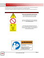
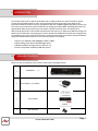
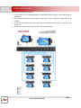
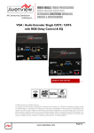
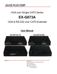
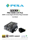
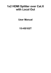
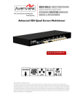
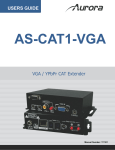
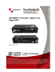
4, 8, 16 Port VGA/ Audio Extender / Splitter With Local Output with SPDIF Model #: VGA-C5SP-8 © 2010 Avenview Inc. All rights reserved. The contents of this document are provided in connection with Avenview Inc. (“Avenview”) products. Avenview makes no representations or warranties with respect to the accuracy or completeness of the contents of this publication and reserves the right to make changes to specifications and product descriptions at any time without notice. No license, whether express, implied, or otherwise, to any intellectual property rights is granted by this publication. Except as set forth in Avenview Standard Terms and Conditions of Sale, Avenview assumes no liability whatsoever, and disclaims any express or implied warranty, relating to its products including, but not limited to, the implied warranty of merchantability, fitness for a particular purpose, or infringement of any intellectual property right. Reproduction of this manual, or parts thereof, in any form, without the express written permission of Avenview Inc. is strictly prohibited. TABLE OF CONTENTS SECTION 1: GETTING STARTED........................................................................................................ 3 1.1 IMPORTANT SAFEGUARDS ................................................................................................ 3 1.2 SAFETY INSTRUCTIONS ..................................................................................................... 3 1.3 REGULATORY NOTICES FEDERAL COMMUNICATIONS COMMISSION (FCC) .......... 4 2. INTRODUCTION ................................................................................................................. 5 2.1 PACKAGE CONTENTS ........................................................................................................ 5 2.2 BEFORE INSTALLATION ..................................................................................................... 6 3. PANEL DESCRIPTION ......................................................................................................... 7 4. INSTALLATION .................................................................................................................... 8 5. GENERAL TROUBLESHOOTING ....................................................................................... 8 SECTION 6: SPECIFICATIONS ............................................................................................................ 9 www.avenview.com Page|2 SECTION 1: GETTING STARTED 1.1 IMPORTANT SAFEGUARDS Please read all of these instructions carefully before you use the device. Save this manual for future reference. What the warranty does not cover Any product, on which the serial number has been defaced, modified or removed. Damage, deterioration or malfunction resulting from: Accident, misuse, neglect, fire, water, lightning, or other acts of nature, unauthorized product modification, or failure to follow instructions supplied with the product. Repair or attempted repair by anyone not authorized by us. Any damage of the product due to shipment. Removal or installation of the product. Causes external to the product, such as electric power fluctuation or failure. Use of supplies or parts not meeting our specifications. Normal wear and tear. Any other causes which does not relate to a product defect. Removal, installation, and set-up service charges. 1.2 SAFETY INSTRUCTIONS The Avenview VGA-C5-SP-4, VGA-C5-SP-8, VGA-C5-SP-16, VGA & Audio Extender/Splitter, Single CAT5 have been tested for conformance to safety regulations and requirements, and has been certified for international use. However, like all electronic equipment’s, the VGA-C5-SP-XX should be used with care. Read the following safety instructions to protect yourself from possible injury and to minimize the risk of damage to the unit. Do not dismantle the housing or modify the module. Dismantling the housing or modifying the module may result in electrical shock or burn. Refer all servicing to qualified service personnel. Do not attempt to service this product yourself as opening or removing housing may expose you to dangerous voltage or other hazards Keep the module away from liquids. Spillage into the housing may result in fire, electrical shock, or equipment damage. If an object or liquid falls or spills on to the housing, unplug the module immediately. Have the module checked by a qualified service engineer before using it again. Do not use liquid or aerosol cleaners to clean this unit. Always unplug the power to the device before cleaning. www.avenview.com Page|3 1.3 REGULATORY NOTICES FEDERAL COMMUNICATIONS COMMISSION (FCC) This equipment has been tested and found to comply with Part 15 of the FCC rules. These limits are designed to provide reasonable protection against harmful interference in a residential installation. Any changes or modifications made to this equipment may void the user’s authority to operate this equipment. Warning symbols Description ONLY USE THE PROVIDED POWER CABLE OR POWER ADAPTER SUPPLIED. DO NOT TAMPER WITH THE ELECTRICAL PARTS. THIS MAY RESULT IN ELECTRICAL SHOCK OR BURN. DO NOT TAMPER WITH THE UNIT. DOING SO WILL VOID THE WARRANTY AND CONTINUED USE OF THE PRODUCT. THE VIDEO BOARDS ARE VERY SENSITIVE TO STATIC. PLEASE ENSURE IF RACK MOUNTED OR INSTALLED ON A SURFACE, IT SHOULD BE IN A GROUNDED ENVIROMENT. www.avenview.com Page|4 2. INTRODUCTION The Avenview VGA-C5-SP-4, VGA-C5-SP-8, VGA-C5-SP-16, VGA and Audio over CAT5 Transmitter / Splitter provides the most flexible solution by which the high resolution Video and high quality stereo Audio can be transmitted to different locations over super long distances. Built with 2 VGA and digital/analog audio loop outs, local A/V receivers can provide extra video and audio fan-outs through typical VGA, SPDIF, and analog audio cables. The high bandwidth VGA can be transmitted up to 65 meters (210 feet) on the local ports. The VGA-C5-SP-4, VGA-C5-SP-8, VGA-C5-SP-16 also extends VGA and stereo audio source up to 330 meters (1000 feet) through cost effective CAT-5 LAN cables. Accompanying the receivers of VGA-C5A-R VGA CAT5 extender series equipped with the equalization, gain control and de-skew functions, the video and audio quality can be further assured and make the quality of overall transmission superior than the other VGA splitters on the market. - Supports up to WUXGA (1920x1200@60) to 300m (1,000ft) Supports Analog Stereo Audio and S/PDIF Digital Audio Adjustable equalization and gain control on Receiver unit De-skew compensation available for RGB delay control 2.1 PACKAGE CONTENTS Before you start the installation of the converter, please check the package contents. 1 1 - VGA-C5SP-8 x1 Power Adapter (+5V 4A DC) 1 User’s Manual 1 Rack Mount Kit www.avenview.com Page|5 2.2 BEFORE INSTALLATION Put the product in an even and stable location. If the product falls down or drops, it may cause an injury or malfunction. Don’t place the product in too high temperature (over 50°C), too low temperature (under 0°C) or high humidity. Use the DC power adapter with correct specifications. If inappropriate power supply is used then it may cause a fire. Do not twist or pull the ends of the UTP cable. It can cause malfunction. www.avenview.com Page|6 3. PANEL DESCRIPTION INPUT PANEL (Receiver, VGA-C5SP-8)Front Panel 1 1. Audio Select Button Down SPDIF/ UP Stereo 2 2. Power LED light OUTPUT PANEL (Receiver, VGA-C5SP-8)Rear panel 3 4 5 6 8 7 9 3. Power Connector 4. VGA Input Female Connector 5. Stereo Audio Input (3.5mm jack) 6. S/PDIF Input (RCA jack) 7. Local Video and Audio Output 8. Local Video and Audio Output (Analog Audio Out 3.5mm & Digital Audio Out RCA) 9. (Analog Audio Out 3.5mm & Digital Audio Out RCA) 8 Bank of RJ45 Outputs to Rx VGA-C5A-R www.avenview.com Page|7 4. INSTALLATION 1. Connect VGA and audio source to Transmitter (VGA-C5-SP8) 2. Connect VGA display and speakers to Receiver (VGA-C5A-R) 3. Connect CAT5/CAT6 cable between Transmitter (VGA-C5-SP8) and Receiver (VGA-C5A-R) 4. Ensure that cables are tightly connected 5. Plug in 5V 2ADC power adapter to the power jack of the Receiver VGA-C5A-R. 6. Plug in 5V 4ADC power adapter to the power jack of the Transmitter VGA-C5-SP8. 5. GENERAL TROUBLESHOOTING PROBLEM POSSIBLE SOLUTION NO IMAGE SCREEN DEFECTS APPEAR 1. 2. Check if connection to the source and the display are correct. Ensure that display device supports the resolution that is being output. This product supports up to WUXGA (1920x1200) resolution. Check the VGA and CAT5 connection If outputting from a PC. Check the maximum resolution range of the graphics card. If a blurred video is seen or even worse, not displayed at all, try to adjust the EQ and Gain rotary controls to improve the cable skew. GAIN rotary controls are designed for gain control, and EQ rotary controls are designed for equalizing the wave form of the receiving video signal. It is suggested to begin with adjusting the rotary control of EQ to get the input video displayed first, and then the GAIN according to the video you see on the screen. RGB delay control [De-skew] offers the flexible functionality to allow skew compensation among VGA R, G, B signals due to long transmission or thru low quality cable. By adjusting the rotary switch to choose R, G or B color channel at first, then use the push buttons to increase or decrease the delay in the corresponding color channel. There are totally 31 steps, each step with 2ns difference, for adjusting the delay between each color individually. Then the graphics quality can be further assured. www.avenview.com Page|8 SECTION 6: SPECIFICATIONS ITEM UNITS UNIT DESCRIPTION VIDEO BANDWIDTH VIDEO SUPPORT SUPPORTED RESOLUTIONS RESOLUTION AND DISTANCE AUDIO SUPPORT EQUALIZATION INPUT VIDEO SIGNAL ESD PROTECTION DESCRIPTION VGA-C5-SP-4 4 Port VGA Extender Splitter VGA-C5-SP-8 8 Port VGA Extender Splitter 350MHz VESA Up to WUXGA (1920 x1200) VGA CONNECTOR RJ45 CONNECTOR 3.5MM AUDIO CONNECTOR RCA CONNECTOR DIMENSIONS (L X W X H) POWER SUPPLY POWER CONSUMPTION Up to 1280x1024 WUXGA 1920x 1200 at 300 meters 1280x1024 at 300 meters (1000 feet) (1000 feet) Stereo Continuous Analog Control 1.2 Volts (peak-to-peak) - Human body model — ±15kV (air-gap discharge) & ±8kV (contact discharge) - Core chipset — ±8kV 1 x VGA 1 x RCA 1 x 3.5mm Audio INPUT OUTPUT VGA-C5-SP-16 16 Port VGA Extender Splitter 2 x VGA 2 x RCA 2 x 3.5mm 4 x RJ45 2 x VGA 2 x RCA 2 x 3.5mm 8 x RJ45 HD-15 (15 pin D-sub Female) WE/SS 8P8C with 2 LED indicators 2 x VGA 2 x RCA 2 x 3.5mm 16 x RJ45 Earphone jack for Analog Stereo Audio S/PDIF Digital Audio 16” x 3.8” x 1.7” 10 Watt (max) 16” x 3.8” x 3.5” 5V 4A DC 15 Watt (max) 25 Watt (max) ENVIRONMENTAL OPERATING TEMPERATURE STORAGE TEMPEARTURE RELATIVE HUMIDITY 32˚ ~ 104˚F (0˚ to 40˚C) -4˚ ~ 140˚F (-20˚ ~ 60˚C) 20~90% RH (no condensation) www.avenview.com Page|9 NOTICE 1. All HDMI over CAT5 transmission distances are measured using Belden 1583A CAT5e 125MHz UTP cable and ASTRODESIGN Video Signal Generator VG-859C. 3. The transmission length is largely affected by the type of category cables, the type of HDMI sources, and the type of HDMI display. The testing result shows solid UTP cables (usually in the form of 300m or 1000ft bulk cable) can transmit a lot longer signals than stranded UTP cables (usually in the form of patch cords). Shielded STP cables are better suit than unshielded UTP cables. A solid UTP CAT5e cable shows longer transmission length than stranded STP CAT6 cable. For long extension users, solid cables are your only choice. 4. EIA/TIA-568-B termination (T568B) for category cables is recommended for better performance. 5. To reduce the interference among the unshielded twisted pairs of wires in category cable, you can use shielded STP cables to improve EMI problems. 6. The quality of UTP/STP cables can affect the transmission distance. 7. The video quality is subject to the resolution of the source, also the connected display should be compatible with the resolution of the source PERFORMANCE GUIDE FOR HDMI OVER CATEGORY CABLE TRANSMISSION PERFORMANCE RATING SHIELDING WIRING SOLID STRANDED TYPE OF CATEGORY CABLE CAT5 CAT5E CAT6 UNSHIELDED (UTP) SHIELDED (STP) UNSHIELDED (UTP) SHIELDED (STP) TERMINATION PLEASE USE EIA/TIA-568-B TERMINATION (T568B) AT ANY TIME www.avenview.com Page|10 Disclaimer While every precaution has been taken in the preparation of this document, Avenview Inc. assumes no liability with respect to the operation or use of Avenview hardware, software or other products and documentation described herein, for any act or omission of Avenview concerning such products or this documentation, for any interruption of service, loss or interruption of business, loss of anticipatory profits, or for punitive, incidental or consequential damages in connection with the furnishing, performance, or use of the Avenview hardware, software, or other products and documentation provided herein. Avenview Inc. reserves the right to make changes without further notice to a product or system described herein to improve reliability, function or design. With respect to Avenview products which this document relates, Avenview disclaims all express or implied warranties regarding such products, including but not limited to, the implied warranties of merchantability, fitness for a particular purpose, and non-infringement. www.avenview.com Page|11