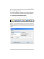
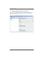
1
GE Measurement & Control Solutions RVI Menu Directed Inspection User’s Manual P/N 816308 Rev. A September 2011 Menu Directed Inspection Version 2.0 User’s Manual P/N 816308 Rev. A September 2011 www.ge-mcs.com ©2011 General Electric Company. All rights reserved. Technical content subject to change without notice. [no content intended for this page] ii Contents Chapter 1. About Menu Directed Inspection (MDI) 1.1 Overview . . . . . . . . . . . . . . . . . . . . . . . . . . . . . . . . . . . . . . . . . . . . . . . . . . . . . . 1 1.2 Pre-Inspection: Plan & Build your Inspection . . . . . . . . . . . . . . . . . . . . . . . . . 2 1.3 Inspection: Use MDI on the VideoProbe . . . . . . . . . . . . . . . . . . . . . . . . . . . . . 2 1.4 Post-Inspection: Report & View the Inspection Results . . . . . . . . . . . . . . . . . . 2 Chapter 2. Pre-Inspection Planning 2.1 Mapping Your Inspection . . . . . . . . . . . . . . . . . . . . . . . . . . . . . . . . . . . . . . . . . 3 2.2 Using MDI Builder Software . . . . . . . . . . . . . . . . . . . . . . . . . . . . . . . . . . . . . . 4 2.2.1 Toolbar Buttons . . . . . . . . . . . . . . . . . . . . . . . . . . . . . . . . . . . . . . . . . . . 4 2.2.2 Setup Tabs . . . . . . . . . . . . . . . . . . . . . . . . . . . . . . . . . . . . . . . . . . . . . . . 5 2.3 Building Your First MDI Inspection . . . . . . . . . . . . . . . . . . . . . . . . . . . . . . . . 12 2.3.1 Adding Inspection Points. . . . . . . . . . . . . . . . . . . . . . . . . . . . . . . . . . . 13 2.3.2 Assigning Characterization Sets . . . . . . . . . . . . . . . . . . . . . . . . . . . . . 15 2.3.3 Assigning Reference Material . . . . . . . . . . . . . . . . . . . . . . . . . . . . . . . 17 Chapter 3. Inspection Procedures 3.1 Loading and Unloading Inspections . . . . . . . . . . . . . . . . . . . . . . . . . . . . . . . . 19 3.1.1 XLG3 . . . . . . . . . . . . . . . . . . . . . . . . . . . . . . . . . . . . . . . . . . . . . . . . . . 19 3.1.2 XL Go . . . . . . . . . . . . . . . . . . . . . . . . . . . . . . . . . . . . . . . . . . . . . . . . . 19 3.2 Performing an Inspection . . . . . . . . . . . . . . . . . . . . . . . . . . . . . . . . . . . . . . . . 20 3.2.1 XLG3 . . . . . . . . . . . . . . . . . . . . . . . . . . . . . . . . . . . . . . . . . . . . . . . . . . 20 3.2.2 XL Go . . . . . . . . . . . . . . . . . . . . . . . . . . . . . . . . . . . . . . . . . . . . . . . . . 22 Chapter 4. Post-Inspection Reports 4.1 Generating a Report . . . . . . . . . . . . . . . . . . . . . . . . . . . . . . . . . . . . . . . . . . . . 25 4.1.1 XLG3 . . . . . . . . . . . . . . . . . . . . . . . . . . . . . . . . . . . . . . . . . . . . . . . . . . 25 4.1.2 XL Go . . . . . . . . . . . . . . . . . . . . . . . . . . . . . . . . . . . . . . . . . . . . . . . . . 25 4.2 Customizing MDI Reports . . . . . . . . . . . . . . . . . . . . . . . . . . . . . . . . . . . . . . . 26 Chapter 5. Tips & Tricks 5.1 Generating Multiple Inspection Points . . . . . . . . . . . . . . . . . . . . . . . . . . . . . . 29 5.2 Resetting Filenames and Annotations . . . . . . . . . . . . . . . . . . . . . . . . . . . . . . . 31 5.3 Changing the Language. . . . . . . . . . . . . . . . . . . . . . . . . . . . . . . . . . . . . . . . . . 33 5.4 Expanding or Collapsing the Inspection Tree . . . . . . . . . . . . . . . . . . . . . . . . . 34 5.5 Designating Study Labels as Displayed/Required . . . . . . . . . . . . . . . . . . . . . 35 Menu Directed Inspection User’s Manual iii Contents [no content intended for this page] iv Menu Directed Inspection User’s Manual Preface Typographical Conventions • Note paragraphs provide information that provides a deeper understanding of the situation, but is not essential to the proper completion of the instructions. • Important paragraphs provide information that emphasizes instructions that are essential to proper setup of the product. Failure to follow these instructions carefully may cause unreliable performance. • Caution! paragraphs provide information that alerts the operator to a hazardous situation that can cause damage to property or equipment. • Warning! paragraphs provide information that alerts the operator to a hazardous situation that can cause injury to personnel. Cautionary information is also included, when applicable. Safety & Regulatory Issues For detailed information on safety and regulatory issues, refer to the user’s manual for your specific GEIT VideoProbe. Menu Directed Inspection User’s Manual v Preface [no content intended for this page] vi Menu Directed Inspection User’s Manual Chapter 1. About Menu Directed Inspection (MDI) Chapter 1. About Menu Directed Inspection (MDI) 1.1 Overview To use the GEIT Menu Directed Inspection (MDI) application effectively, three general steps must be completed. As illustrated in Figure 1 below, these steps are: • Pre-Inspection • Inspection • Post-Inspection One-Time Step Repeatable Steps Figure 1: MDI Workflow Overview Proceed to the next page for a more detailed description of the above steps. Menu Directed Inspection User’s Manual 1 Chapter 1. About Menu Directed Inspection (MDI) 1.2 Pre-Inspection: Plan & Build your Inspection Using the MDI Builder application on your PC allows you to turn your inspection plan into a digital map that can be loaded onto your GEIT VideoProbe. You can use the MDI Builder application to define the specific information that you want to capture during inspection. The file created using the MDI Builder may be used multiple times on your VideoProbe. For example, if you create an inspection plan for a CFM56 engine, you can use that plan to perform multiple inspections on multiple CFM56 engines. For more information on building your inspection plan, refer to “Pre-Inspection Planning” on page 3. 1.3 Inspection: Use MDI on the VideoProbe After you have built an inspection plan, you need to load the file onto your GEIT VideoProbe. You can then use the digital inspection plan to ensure that you are capturing all of the data that you intended to capture. Once you have completed your inspection, you can automatically generate an inspection report on the VideoProbe. For more information on using Menu Directed Inspection, refer to “Inspection Procedures” on page 19. 1.4 Post-Inspection: Report & View the Inspection Results After completing your inspection, the inspection results can be found in files on your PC. These files have names that indicate their content. Each completed inspection creates a unique file folder on your PC that contains your results. Each such inspection folder includes all of the information required to use the GEIT Rhythm data management software. For more information on working with Menu Directed Inspection reports, refer to “Post-Inspection Reports” on page 25. 2 Menu Directed Inspection User’s Manual Chapter 2. Pre-Inspection Planning Chapter 2. Pre-Inspection Planning 2.1 Mapping Your Inspection To begin using Menu Directed Inspection, you need to think about your inspection as a multi-level process. Each inspection defined using Menu Directed Inspection consists of both “study level” information and “inspection point level” information. These are defined as follows: • Study Level Tags - This is the information captured at the beginning of each inspection. The study level tags are printed on the cover page of all reports generated by the Menu Directed Inspection software. • Study Level Information - This information is specific to a particular inspection occurrence. Some examples of study level information are: Date, Inspector Name, Inspection Location, and Asset Serial Number. You can use the MDI Builder Software on your PC to define the specific information that you want to capture every time the MDI is run on a VideoProbe. • Inspection Point Level Tags - This is the information that is associated with each image within reports generated by the Menu Directed Inspection software. • Inspection Point Level Information - This information is specific to images captured during your inspection. Typically, the information describes the location of an inspection point within an asset. Some examples of inspection level information are: Section, Component, Detail, Tube Number or Weld Number. You can use the MDI Builder Software on your PC to define the specific information that you wish to capture. • Characterization - This information provides specific characterization to a particular part or defect. Some examples include crack, dent, pit or corrosion. • Reference Material - This is one or more documents that will be referenced during an inspection. Examples include manuals, TILs, Service Bulletins, sample images of good/bad parts or sample images of defects. Note: Characterization, Reference Material and some reporting options are available on the XLG3 and XL Go+ only. Menu Directed Inspection User’s Manual 3 Chapter 2. Pre-Inspection Planning 2.2 Using MDI Builder Software To map out your inspection, use the MDI Builder software on your PC, as described in the following sections. 2.2.1 Toolbar Buttons The toolbar buttons in the MDI Builder software are shown in Figure 2 below. Figure 2: MDI Builder Toolbar Buttons 1. Create a New MDI File 2. Open an Existing MDI File 3. Close the Open MDI File 4. Save 5. Save As 6. Add an Inspection Point 7. Delete the Selected Inspection Point 8. Cut the Selected Inspection Point 9. Copy the Selected Inspection Point 10. Paste an Inspection Point from Memory 11. Move the Selected Inspection Point Down One Level 12. Move the Selected Inspection Up Down One Level 13. Reset the Filenames and Annotations for the Entire Inspection Tree 4 Menu Directed Inspection User’s Manual Chapter 2. Pre-Inspection Planning 2.2.1 Toolbar Buttons (cont.) 14. Generate Multiple Inspection Points Based on a Pattern 15. Exit the MDI Builder Application 2.2.2 Setup Tabs The multiple setup tabs available in MDI Builder software allow you to modify the Study Level and Inspection Point Level tags that label your inspections and images, as well as setup Characterizations and Reference Material. 2.2.2a Inspection Tab The Inspection tab (see Figure 3 on page 6) displays your inspection tree as you build it. When an inspection point is selected, you can see the defined Label that you associated with that point, the Inspection Point definition, the Filename generated by the inspection point, and the annotation generated by the inspection point. If the selected level of your inspection tree is not the final level, the contribution to filename and contribution to annotation will be displayed. This is because only the final levels of the inspection tree define the full filename and Annotation that is used within your inspection. Menu Directed Inspection User’s Manual 5 Chapter 2. Pre-Inspection Planning 2.2.2a Inspection Tab (cont.) Figure 3: MDI Builder - Inspection Tab For example, the highlighted inspection point in Figure 3 above is part of a multi-level inspection. “Gear Box” is the first level, “1st Planet Stage” is the second level, and “Planetary Pinions” is the third level. These levels are used as illustrated below to construct the filename and annotation associated with the highlighted inspection point. Planetary Pinions Gear Box _ 1st Planet Stage _ Level 1 Level 2 Level 3 Note: A maximum of 1500 inspection points are allowed, and a maximum of five inspection levels are allowed. 6 Menu Directed Inspection User’s Manual Chapter 2. Pre-Inspection Planning 2.2.2b Setup Inspection Labels Tab The Setup Inspection Labels tab, as shown in Figure 4 below, displays the labels specific to a particular inspection occurrence for the information you wish to capture. When performing an inspection on a VideoProbe, the user is asked to enter the information for each label defined in this tab. The information is then displayed on the cover page of all reports generated by the Menu Directed Inspection software. Figure 4: MDI Builder - Setup Inspection Labels Tab Note: A maximum of 19 Inspection Labels are allowed. Menu Directed Inspection User’s Manual 7 Chapter 2. Pre-Inspection Planning 2.2.2c Setup Image Labels Tab The Setup Image Labels tab, as shown in Figure 5 below, displays the text used to label the different levels of your inspection tree. Each inspection point has a specific label that corresponds to each image within the reports generated by the Menu Directed Inspection software. Figure 5: MDI Builder - Setup Image Labels Tab Note: Characterization's default label is “Characterization”. You may customize it to be “Observation”, “Defect ID”, or another identifier. 8 Menu Directed Inspection User’s Manual Chapter 2. Pre-Inspection Planning 2.2.2d Characterization Tab The Characterization tab, as shown in Figure 6 below, displays the Characterization Sets that have been created for an inspection. Figure 6: MDI Builder - Characterization Tab Note: A maximum of 50 characterization sets are allowed per inspection, and a maximum of 50 characterizations are allowed per set. It is best to organize the characterizations by placing the most common characterizations at the top of the list. • Allow “Other” To allow the VideoProbe operator to enter a characterization not already associated with an inspection point, check the box next to Allow user to select “Other” and create a characterization on the VideoProbe. • Import/Export To save characterization sets for use in a future MDI file, the option to import or export is available on the Characterization tab. Menu Directed Inspection User’s Manual 9 Chapter 2. Pre-Inspection Planning 2.2.2e Reference Material Tab The Reference Material tab, as shown in Figure 7 below, displays jpg, bmp or pdf documents that will be referenced during an inspection. The current reference material size is displayed in this tab. Use the chart below to keep your reference material within the recommended limits. Figure 7: MDI Builder - Reference Material Tab Note: A maximum of 50 pieces of reference material are allowed per inspection. Use the compatibility tab for acceptable file types for your VideoProbe. 10 Menu Directed Inspection User’s Manual Chapter 2. Pre-Inspection Planning 2.2.2f Compatibility Tab The Compatibility tab, as show in Figure 8 below, displays the features available for different configurations of GE VideoProbes. Use this tab to ensure you have built a MDI inspection that is compatible with your VideoProbe. Figure 8: MDI Builder - Compatibility Tab Menu Directed Inspection User’s Manual 11 Chapter 2. Pre-Inspection Planning 2.3 Building Your First MDI Inspection When you first open the MDI Builder software, you should go to the Inspection tab and do the following (see Figure 9 below): 1. Name your inspection. 2. Add your first inspection point. 3. Name your first inspection point. Figure 9: Entering Your First Inspection Point 12 Menu Directed Inspection User’s Manual Chapter 2. Pre-Inspection Planning 2.3.1 Adding Inspection Points You may add inspection points as sub-levels to any existing inspection points, in a manner similar to bulleted lists with sub-bullets. To do this, select an existing inspection point and add a new inspection point. As shown in Figure 10 below, your new inspection point is added as a sub-level of the existing inspection point. Figure 10: Adding Sub-Level Inspection Points Menu Directed Inspection User’s Manual 13 Chapter 2. Pre-Inspection Planning 2.3.1 Adding Inspection Points (cont.) Continue to add inspection points until you have completely documented your inspection process. When complete, you should have an inspection tree with multiple levels and multiple inspection points, similar to the tree shown in Figure 11 below. Figure 11: Typical Completed Inspection Tree Note: It is recommended that you save your MDI files on external media, so that they may be loaded onto a VideoProbe easily. For advanced methods of building an inspection, refer to “Tips & Tricks” on page 29. 14 Menu Directed Inspection User’s Manual Chapter 2. Pre-Inspection Planning 2.3.2 Assigning Characterization Sets To assign a Characterization Set to an inspection point, click on the inspection point then click on “Select Characterization” (see Figure 12 below). To assign a Characterization Set to sub-levels of an inspection, click on the top-level folder then click on “Assign characterization set to all sub-nodes”. Figure 12: Assigning Characterization Sets Menu Directed Inspection User’s Manual 15 Chapter 2. Pre-Inspection Planning 2.3.2 Assigning Characterization Sets (cont.) To require a VideoProbe operator to assign a Characterization before proceeding to the next inspection point, check the box next to “Characterization is required on VideoProbe” (see Figure 13 below). Figure 13: Requiring a Characterization 16 Menu Directed Inspection User’s Manual Chapter 2. Pre-Inspection Planning 2.3.3 Assigning Reference Material To assign Reference Material to an inspection point, click on the inspection point then click on “Select Reference Material” (see Figure 14 below). To assign Reference Material to sub-levels of an inspection, click on the top-level folder then click on “Assign Reference Material set to all sub-nodes”. Figure 14: Assigning Reference Material Menu Directed Inspection User’s Manual 17 Chapter 2. Pre-Inspection Planning 2.3.3 Assigning Reference Material (cont.) To assign a certain page of a pdf, type the page number into the box next to the reference pdf (see Figure 15 below). If using more than one page, separate the page numbers by a comma. Figure 15: Assigning Pages from a PDF File 18 Menu Directed Inspection User’s Manual Chapter 3. Inspection Procedures Chapter 3. Inspection Procedures 3.1 Loading and Unloading Inspections To load or unload a Menu Directed Inspection on a VideoProbe, proceed to the section below for your GEIT VideoProbe model. Note: MDI inspection files have the file extension of .mdz. A maximum of five MDI inspection files may be loaded on a VideoProbe at any given time. 3.1.1 XLG3 Use the following menu to load and unload MDI inspections on the XLG3 VideoProbe: MENU>SETUP>SYSTEM>MDI 3.1.2 XL Go Use the following menu to load and unload MDI inspections on the XL Go VideoProbe: LIVE MAIN MENU>SETUP>SYSTEM TOOLS>MDI Note: On the XL Go, the LIVE MAIN MENU is accessed using a joystick press or by holding the GOTO MENU button, which is the right Soft Key in live mode, for five seconds. Menu Directed Inspection User’s Manual 19 Chapter 3. Inspection Procedures 3.2 Performing an Inspection To perform an MDI inspection on a VideoProbe, proceed to the appropriate section for your GEIT VideoProbe model. 3.2.1 XLG3 To perform an inspection on the XLG3 VideoProbe, follow the instructions in the following sections. 3.2.1a Starting an Inspection To start an inspection using MDI, select the following menu option: MENU>MENU DIRECTED INSPECTION>(INSPECTION NAME) 3.2.1b Entering Study Level Information At the start of an MDI inspection, you are prompted to enter the study level information and to select the PC drive that will be used to save your inspection results. You can use either the on-screen keyboard or an external USB keyboard to enter your information on the VideoProbe. Note: For a list of supported keyboards, see your VideoProbe user's manual. 3.2.1c Selecting an Inspection Point At this time, a list of your inspection points, which is organized by level, is displayed. To select the desired level, press either the Enter button or the Trigger. Continue to navigate through the inspection levels until you have reached the desired inspection point. To view Reference Material associated with this inspection point press and hold the menu key. Alternatively, go to the following menu: MENU > (INSPECTION NAME) > REFERENCE MATERIAL When you see the annotation for the selected inspection point at the top of your screen, you may save an image or video of that inspection point. To select a different inspection point, do either one of the following: • Hold the BACK button for two seconds • Select MENU>(INSPECTION NAME)>LIST 20 Menu Directed Inspection User’s Manual Chapter 3. Inspection Procedures 3.2.1d Saving an Image To save an image of the selected inspection point, press the SAVE button. During the save process, the following options are available: • Required Characterization - If Characterization is required, the characterization set list will appear before the save menu. An option must be selected to move forward. • Save - This option saves the image with the associated MDI data and filename. • Save with Flag - This option saves the image with “-FLAG” appended onto the filename. If you use this option, you can then generate a report that includes only the flagged images. • Characterization - This option allows you to assign characterization to this image. • Add Comments - This option allows you to save comments along with the image. When generating a report, these comments are associated with the specific image. Images saved using MDI are located in the inspection folder created at the beginning of the inspection. They are given file names based on your designated inspection points, and have meta data associated with them to ensure that they communicate with data management software such as GEIT Rhythm. 3.2.1e Recording a Video To record a video of the selected inspection point, press the RECORD button. Videos recorded using MDI are located in the inspection folder created at the beginning of the inspection. They are given file names based on your designated inspection points. Menu Directed Inspection User’s Manual 21 Chapter 3. Inspection Procedures 3.2.1f Stopping & Resuming an Inspection To stop an inspection, which may be resumed or finished at a later time, go to the inspection list (see “Selecting an Inspection Point” on page 20) and select STOP. To resume a previously stopped inspection, go to the following menu: MENU>MENU DIRECTED INSPECTION>RESUME Then, you may either resume the last inspection or browse for a previous inspection to be resumed. 3.2.2 XL Go To perform an inspection on the XL Go VideoProbe, follow the instructions in the following sections. 3.2.2a Starting an Inspection To perform an inspection using MDI, select the following menu option: LIVE MAIN MENU>MDI>(INSPECTION NAME) 3.2.2b Entering Study Level Information At the start of an MDI inspection, you are prompted to enter the study level information and to select the PC drive that will be used to save your inspection results. You can use either the on-screen keyboard or an external USB keyboard to enter your information on the VideoProbe. Note: For a list of supported keyboards, see your VideoProbe user's manual. 22 Menu Directed Inspection User’s Manual Chapter 3. Inspection Procedures 3.2.2c Selecting an Inspection Point At this time, a list of your inspection points, which is organized by level, is displayed. To select the desired level, either press the right Soft Key or use the Joystick to navigate left or right. Continue to navigate through the inspection levels until you have reached the desired inspection point. To view Reference Material associated with this inspection point, go to the following menu: GOTO MENU > (INSPECTION NAME) > REFERENCE MATERIAL When you see the annotation for the selected inspection point at the top of your screen, you may save an image or video of that inspection point. To select a different inspection point, go to the following menu: GOTO MENU>(INSPECTION NAME)>CONTINUE 3.2.2d Saving an Image To save an image of the selected inspection point, press the ENTER button and then select SAVE. During the save process, the following options are available: • Required Characterization - If Characterization is required, the characterization set list will appear before the save menu. An option must be selected to move forward. • Save - This option saves the image with the associated MDI data and filename. • Save with Flag - This option saves the image with “-FLAG” appended onto the filename. If you use this option, you can then generate a report that includes only the flagged images. • Characterization - This option allows you to assign characterization to this image. • Add Comments - This option allows you to save comments along with the image. When generating a report, these comments are associated with the specific image. Images saved using MDI are located in the inspection folder created at the beginning of the inspection. They are given file names based on your designated inspection points, and have metadata associated with them to ensure that they communicate properly with data management software such as GEIT Rhythm. Menu Directed Inspection User’s Manual 23 Chapter 3. Inspection Procedures 3.2.2e Recording a Video To record a video of the selected inspection point, hold the RECORD button for two seconds. Videos recorded using MDI are located in the inspection folder created at the beginning of the inspection. They are given file names based on your designated inspection points. 3.2.2f Stopping & Resuming an Inspection To stop an inspection, which may be resumed or finished at a later time, enter the following key strokes: GOTO MENU>(INSPECTION NAME)>STOP To resume a previously stopped inspection, enter the following key strokes: LIVE MAIN MENU>MDI>RESUME>(INSPECTION NAME) Then, you may either resume the last inspection or browse for a previous inspection to be resumed. 24 Menu Directed Inspection User’s Manual Chapter 4. Post-Inspection Reports Chapter 4. Post-Inspection Reports 4.1 Generating a Report After completing your inspection, you are ready to generate an MDI report. For instructions on this procedure, go to the appropriate section below for your GEIT VideoProbe model. 4.1.1 XLG3 Use the following menu to generate a report on the XLG3 VideoProbe: MENU>MENU DIRECTED INSPECTION> GENERATE REPORT>(DRIVE)>(INSPECTION NAME) 4.1.2 XL Go After completing your inspection, you can automatically generate an MDI report on the XL Go VideoProbe in MS Word format by entering the following key strokes: GOTO MENU>(INSPECTION NAME)>REPORT Note: Reports can be customized with cover pages, end notes, different image options, etc. (see “Customizing MDI Reports” on page 26). After designating your preferences for Report Name, Images to Include, Image Layout, Cover Page, and End Note, press ENTER to generate your report. Note: For more information see “Tips & Tricks” on page 29. Reports generated on the XL Go are saved as executable files (*.exe). To convert these to MS Word documents, simply run the executable file on your PC. Menu Directed Inspection User’s Manual 25 Chapter 4. Post-Inspection Reports 4.2 Customizing MDI Reports On both the XLG3 and the XL Go VideoProbes, you can customize your inspection report by specifying the following parameters: • Report Name - Override the automatic inspection report file name. • Include Images - Select either all images or only flagged images to be included in the inspection report. • Image Layout • Images with Details - Include a table of information about the image in the report. • Images Only - Include only images and file names in the report. • Image Size - Select one of the following image sizes to be included in the inspection report: • Extra Small • Small • Medium • Large • Image Layout - Select one of the following image layouts to be used in the inspection report: • Image right of text • Image left of text • Image above text • Image below text 26 Menu Directed Inspection User’s Manual Chapter 4. Post-Inspection Reports 4.2 • • Customizing MDI Reports Cover Page - Select the cover page to be included in the inspection report. • FACTORY DEFAULT - Use the factory default settings for all parameters. • BROWSE - Select an MS Word document to be used as your inspection report cover page. End Note - Select the pages to be included as the last pages of the inspection report • NONE - Don’t include any custom features in your inspection report. • BROWSE - Select an MS Word document to be included as your inspection report end note. Menu Directed Inspection User’s Manual 27 Chapter 4. Post-Inspection Reports [no content intended for this page] 28 Menu Directed Inspection User’s Manual Chapter 5. Tips & Tricks Chapter 5. Tips & Tricks The information in this chapter is intended to provide you with information to help you use all of the MDI software features more effectively and more efficiently. 5.1 Generating Multiple Inspection Points You can add multiple inspection points, based on a pattern, at one time by using the Advanced Add toolbar button highlighted in Figure 16 below. Figure 16: The Advanced Add Toolbar Button To use this feature, you must first choose the pattern to be used for your inspection points. As shown in Figure 17 below, the fields for Text1 and Text2 are repeated for each inspection point, while the +n field is incremented after each inspection point is added. Figure 17: Advanced Add Data Entry Window Menu Directed Inspection User’s Manual 29 Chapter 5. Tips & Tricks 5.1 Generating Multiple Inspection Points (cont.) As you enter your inspection point pattern in the Advanced Add window (see Figure 17 on page 29), the inspection points are added to the inspection tree, as shown in Figure 18 below. Figure 18: Inspection Tree with New Points Added 30 Menu Directed Inspection User’s Manual Chapter 5. Tips & Tricks 5.2 Resetting Filenames and Annotations MDI Builder automatically constructs your file names based on the structure of your inspection tree. For example, in Figure 19 below the first level of the inspection tree is “InspectionPoint1” (1) and the highlighted second level is “SubLevel2” (2). The automatic file name for this inspection point is “InspectionPoint1_SubLevel2XXX” (3) and the automatic annotation is “InspectionPoint1 SubLevel2” (4). The MDI Builder gives you the option of changing the automatic text strings by overriding the “Filename” (3) and/or “Annotation” (4) fields. Figure 19: Automatic Filenames and Annotations Menu Directed Inspection User’s Manual 31 Chapter 5. Tips & Tricks 5.2 Resetting Filenames and Annotations (cont.) If you have changed your filenames and/or annotations but later decide that you prefer the automatic text strings, simply select the Reset Filenames/Annotations toolbar button highlighted in Figure 20 below. Figure 20: The Reset Filenames/Annotations Toolbar Button Selecting the Reset Filenames/Annotations toolbar button opens a window similar to Figure 21 below. Then, select “Filenames” or “Annotations” or “Both” to reset the desired text strings. Figure 21: Reset Filenames and Annotations 32 Menu Directed Inspection User’s Manual Chapter 5. Tips & Tricks 5.3 Changing the Language MDI Builder comes pre-loaded with eleven languages. To change the language used, select the following menu: File>Languages>(Language Name) When the above menu is selected, a window similar to Figure 22 below opens. Simply choose the desired display language on the drop-down list. Figure 22: List of Available Languages Note: For the language change to take place, you must restart the MDI Builder application. IMPORTANT: Remember to save your inspection before restarting the MDI Builder application. Menu Directed Inspection User’s Manual 33 Chapter 5. Tips & Tricks 5.4 Expanding or Collapsing the Inspection Tree To quickly expand or collapse your inspection tree, select one of the following menu options (see Figure 23 below): Edit>Expand Inspection Tree or Edit>Collapse Inspection Tree Figure 23: The Expand/Collpase Inspection Tree Menu 34 Menu Directed Inspection User’s Manual Chapter 5. Tips & Tricks 5.5 Designating Study Labels as Displayed/Required You may designate your Study Labels as Displayed and/or Required using the “Study Labels (Cover Page)” tab in the MDI builder. If the label highlighted in Figure 24 below is not Displayed, an inspector will not see this as a field while using MDI on the VideoProbe. If a label is Required, an inspector will need to populate this field before continuing with their inspection on the VideoProbe. Figure 24: MDI Builder - Study Labels (Cover Page) Tab Menu Directed Inspection User’s Manual 35 Chapter 5. Tips & Tricks [no content intended for this page] 36 Menu Directed Inspection User’s Manual Index A Advanced Add Toolbar Button . . . . . . . . . . . . . . . . . . . . . . . . . . . . . . . . . . . . . . . 29 Annotations, Resetting . . . . . . . . . . . . . . . . . . . . . . . . . . . . . . . . . . . . . . . . . . . . . . 31 C Characterization Description . . . . . . . . . . . . . . . . . . . . . . . . . . . . . . . . . . . . . . . . . . . . . . . . . . . . 3 Requiring. . . . . . . . . . . . . . . . . . . . . . . . . . . . . . . . . . . . . . . . . . . . . . . . . . . . . 16 Characterization Sets, Assigning . . . . . . . . . . . . . . . . . . . . . . . . . . . . . . . . . . . . . . 15 Characterization Tab, Description . . . . . . . . . . . . . . . . . . . . . . . . . . . . . . . . . . . . . . 9 Collapsing the Inspection Tree. . . . . . . . . . . . . . . . . . . . . . . . . . . . . . . . . . . . . . . . 34 Compatibility Tab, Description . . . . . . . . . . . . . . . . . . . . . . . . . . . . . . . . . . . . . . . 11 Customizing Reports . . . . . . . . . . . . . . . . . . . . . . . . . . . . . . . . . . . . . . . . . . . . . . . 26 D Displaying Study Labels. . . . . . . . . . . . . . . . . . . . . . . . . . . . . . . . . . . . . . . . . . . . . 35 Document Number . . . . . . . . . . . . . . . . . . . . . . . . . . . . . . . . . . . . . . . . . . . . . . . . . . i E Expanding the Inspection Tree. . . . . . . . . . . . . . . . . . . . . . . . . . . . . . . . . . . . . . . . 34 F Files see MDI Files I Images, Saving . . . . . . . . . . . . . . . . . . . . . . . . . . . . . . . . . . . . . . . . . . . . . . . . . 21, 23 Inspection Point Level Information, Description . . . . . . . . . . . . . . . . . . . . . . . . . . . 3 Inspection Point Level Tags, Description . . . . . . . . . . . . . . . . . . . . . . . . . . . . . . . . 3 Inspection Points Adding . . . . . . . . . . . . . . . . . . . . . . . . . . . . . . . . . . . . . . . . . . . . . . . . . . . . . . . 13 Entering . . . . . . . . . . . . . . . . . . . . . . . . . . . . . . . . . . . . . . . . . . . . . . . . . . . . . . 12 Generating Multiple . . . . . . . . . . . . . . . . . . . . . . . . . . . . . . . . . . . . . . . . . . . . 29 Maximum Allowed . . . . . . . . . . . . . . . . . . . . . . . . . . . . . . . . . . . . . . . . . . . . . . 6 Selecting . . . . . . . . . . . . . . . . . . . . . . . . . . . . . . . . . . . . . . . . . . . . . . . . . . 20, 23 Inspection Tab, Description . . . . . . . . . . . . . . . . . . . . . . . . . . . . . . . . . . . . . . . . . . . 5 Inspection Tree Example. . . . . . . . . . . . . . . . . . . . . . . . . . . . . . . . . . . . . . . . . . . . . . . . . . . . . . 14 Expanding/Collapsing . . . . . . . . . . . . . . . . . . . . . . . . . . . . . . . . . . . . . . . . . . . 34 Menu Directed Inspection User’s Manual 37 Index Inspections Generating a Report . . . . . . . . . . . . . . . . . . . . . . . . . . . . . . . . . . . . . . . . . . . . 25 Loading/Unloading on VideoProbe . . . . . . . . . . . . . . . . . . . . . . . . . . . . . . . . 19 Performing . . . . . . . . . . . . . . . . . . . . . . . . . . . . . . . . . . . . . . . . . . . . . . . . . . . 20 Planning . . . . . . . . . . . . . . . . . . . . . . . . . . . . . . . . . . . . . . . . . . . . . . . . . . . . . . 3 Resuming . . . . . . . . . . . . . . . . . . . . . . . . . . . . . . . . . . . . . . . . . . . . . . . . . 22, 24 Starting . . . . . . . . . . . . . . . . . . . . . . . . . . . . . . . . . . . . . . . . . . . . . . . . . . . 20, 22 Stopping . . . . . . . . . . . . . . . . . . . . . . . . . . . . . . . . . . . . . . . . . . . . . . . . . . 22, 24 L Language, Changing . . . . . . . . . . . . . . . . . . . . . . . . . . . . . . . . . . . . . . . . . . . . . . . 33 M MDI Builder Creating Inspections . . . . . . . . . . . . . . . . . . . . . . . . . . . . . . . . . . . . . . . . . . . . . 4 Setup Tabs. . . . . . . . . . . . . . . . . . . . . . . . . . . . . . . . . . . . . . . . . . . . . . . . . . . . . 5 Toolbar Buttons . . . . . . . . . . . . . . . . . . . . . . . . . . . . . . . . . . . . . . . . . . . . . . . . 4 MDI Files Automatic Naming . . . . . . . . . . . . . . . . . . . . . . . . . . . . . . . . . . . . . . . . . . . . . . 6 Filename Extension. . . . . . . . . . . . . . . . . . . . . . . . . . . . . . . . . . . . . . . . . . . . . 19 Resetting Names . . . . . . . . . . . . . . . . . . . . . . . . . . . . . . . . . . . . . . . . . . . . . . . 31 Storage . . . . . . . . . . . . . . . . . . . . . . . . . . . . . . . . . . . . . . . . . . . . . . . . . . . . . . 14 Multiple Inspection Points, Generating . . . . . . . . . . . . . . . . . . . . . . . . . . . . . . . . . 29 O Overview Inspection . . . . . . . . . . . . . . . . . . . . . . . . . . . . . . . . . . . . . . . . . . . . . . . . . . . . . 2 Post-Inspection . . . . . . . . . . . . . . . . . . . . . . . . . . . . . . . . . . . . . . . . . . . . . . . . . 2 Pre-Inspection . . . . . . . . . . . . . . . . . . . . . . . . . . . . . . . . . . . . . . . . . . . . . . . . . . 2 Workflow . . . . . . . . . . . . . . . . . . . . . . . . . . . . . . . . . . . . . . . . . . . . . . . . . . . . . 1 R Recording a Video . . . . . . . . . . . . . . . . . . . . . . . . . . . . . . . . . . . . . . . . . . . . . . 21, 24 Reference Material Assigning . . . . . . . . . . . . . . . . . . . . . . . . . . . . . . . . . . . . . . . . . . . . . . . . . . . . 17 Assigning PDF Pages . . . . . . . . . . . . . . . . . . . . . . . . . . . . . . . . . . . . . . . . . . . 18 Description . . . . . . . . . . . . . . . . . . . . . . . . . . . . . . . . . . . . . . . . . . . . . . . . . . . . 3 Viewing. . . . . . . . . . . . . . . . . . . . . . . . . . . . . . . . . . . . . . . . . . . . . . . . . . . 20, 23 Reference Material Tab, Description . . . . . . . . . . . . . . . . . . . . . . . . . . . . . . . . . . . 10 38 Menu Directed Inspection User’s Manual Index Reports Customizing . . . . . . . . . . . . . . . . . . . . . . . . . . . . . . . . . . . . . . . . . . . . . . . . . . 26 Generating . . . . . . . . . . . . . . . . . . . . . . . . . . . . . . . . . . . . . . . . . . . . . . . . . . . . 25 Requiring Study Labels . . . . . . . . . . . . . . . . . . . . . . . . . . . . . . . . . . . . . . . . . . . . . 35 Reset Filenames/Annotations Toolbar Button . . . . . . . . . . . . . . . . . . . . . . . . . . . . 32 Resetting Annotations . . . . . . . . . . . . . . . . . . . . . . . . . . . . . . . . . . . . . . . . . . . . . . . . . . . 31 MDI File Names . . . . . . . . . . . . . . . . . . . . . . . . . . . . . . . . . . . . . . . . . . . . . . . 31 Resuming an Inspection . . . . . . . . . . . . . . . . . . . . . . . . . . . . . . . . . . . . . . . . . . 22, 24 S Safety, VideoProbe. . . . . . . . . . . . . . . . . . . . . . . . . . . . . . . . . . . . . . . . . . . . . . . . . . v Saving an Image . . . . . . . . . . . . . . . . . . . . . . . . . . . . . . . . . . . . . . . . . . . . . . . . 21, 23 Setup Image Labels Tab, Description . . . . . . . . . . . . . . . . . . . . . . . . . . . . . . . . . . . 8 Setup Inspection Labels Tab, Description . . . . . . . . . . . . . . . . . . . . . . . . . . . . . . . . 7 Setup Tabs Characterization . . . . . . . . . . . . . . . . . . . . . . . . . . . . . . . . . . . . . . . . . . . . . . . . 9 Compatibility. . . . . . . . . . . . . . . . . . . . . . . . . . . . . . . . . . . . . . . . . . . . . . . . . . 11 Inspection Tab . . . . . . . . . . . . . . . . . . . . . . . . . . . . . . . . . . . . . . . . . . . . . . . . . . 5 Reference Material . . . . . . . . . . . . . . . . . . . . . . . . . . . . . . . . . . . . . . . . . . . . . 10 Screen Image . . . . . . . . . . . . . . . . . . . . . . . . . . . . . . . . . . . . . . . . . . . . . . . . . . . 6 Setup Image Labels . . . . . . . . . . . . . . . . . . . . . . . . . . . . . . . . . . . . . . . . . . . . . . 8 Setup Inspection Labels . . . . . . . . . . . . . . . . . . . . . . . . . . . . . . . . . . . . . . . . . . 7 Stopping an Inspection . . . . . . . . . . . . . . . . . . . . . . . . . . . . . . . . . . . . . . . . . . . 22, 24 Study Level Information Description . . . . . . . . . . . . . . . . . . . . . . . . . . . . . . . . . . . . . . . . . . . . . . . . . . . . 3 Entering . . . . . . . . . . . . . . . . . . . . . . . . . . . . . . . . . . . . . . . . . . . . . . . . . . . 20, 22 Study Level Labels, Designating as Displayed/Required . . . . . . . . . . . . . . . . . . . 35 Study Level Tags, Description . . . . . . . . . . . . . . . . . . . . . . . . . . . . . . . . . . . . . . . . . 3 T Tags see Study Level Tags or Inspection Point Level Tags Toolbar Buttons Advanced Add. . . . . . . . . . . . . . . . . . . . . . . . . . . . . . . . . . . . . . . . . . . . . . . . . 29 Complete List . . . . . . . . . . . . . . . . . . . . . . . . . . . . . . . . . . . . . . . . . . . . . . . . . . 4 Reset Filenames/Annotations . . . . . . . . . . . . . . . . . . . . . . . . . . . . . . . . . . . . . 32 Typographical Conventions . . . . . . . . . . . . . . . . . . . . . . . . . . . . . . . . . . . . . . . . . . . v Menu Directed Inspection User’s Manual 39 Index V Video, Recording . . . . . . . . . . . . . . . . . . . . . . . . . . . . . . . . . . . . . . . . . . . . . . . 21, 24 VideoProbe Generating a Report . . . . . . . . . . . . . . . . . . . . . . . . . . . . . . . . . . . . . . . . . . . . 25 Loading/Unloading Inspections . . . . . . . . . . . . . . . . . . . . . . . . . . . . . . . . . . . 19 Performing Inspections, XL Go . . . . . . . . . . . . . . . . . . . . . . . . . . . . . . . . . . . 22 Performing Inspections, XLG3. . . . . . . . . . . . . . . . . . . . . . . . . . . . . . . . . . . . 20 Safety . . . . . . . . . . . . . . . . . . . . . . . . . . . . . . . . . . . . . . . . . . . . . . . . . . . . . . . . v W Workflow Overview . . . . . . . . . . . . . . . . . . . . . . . . . . . . . . . . . . . . . . . . . . . . . . . . 1 40 Menu Directed Inspection User’s Manual Customer Support Centers North/South America 721 Visions Drive Skaneateles, NY 13152 U.S.A. Tel: 888-332-3848 (toll-free) 315-554-2000, ext. 1 Europe Lotzenäcker 4 72379 Hechingen Germany Tel: +49 (0)7471 9882 0 Asia/Pacific Floor 5, Linkchart Center 2 Tai Yip Street Kwun Tong, Kowloon Hong Kong Tel: +852 2877 0801 E-mail: [email protected] www.ge-mcs.com ©2011 General Electric Company. All rights reserved. Technical content subject to change without notice. P/N 816308 Rev. A