1
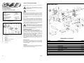
UK
Subject to change
USER’S MANUAL
Document Ref:
FHB-940/15092/PMR43/Issue 1/July 02
Copyright ©
These instructions are the sole property of Ferm-Omega Tools and may not be reproduced
Ferm Wood Lathe
FHB-940
Art.nr. 760140
Screwfix Art.nr. 15092
Ferm BV • P.O. Box 134 • 8280 AC Genemuiden • NL • www.ferm.com
0211/06
SAFETY INSTRUCTIONS
The following pictograms are used in these instructions
for use:
FERM WOOD LATHE FHB-940
USERS MANUAL
TECHNICAL SPECIFICATIONS
Voltage
Frequency
Power
Noload speed (-/min)
Number of speeds
Headstock /
morse taper & threaded
Tailstock / morse taper
Overall dim (mm)
Weight
PRODUCT INFORMATION
|
|
|
|
|
|
|
|
|
|
230 V~
50 Hz
370 W
480-3010
5
No.1, 3/4-16
No.1
375x400x308
38 kg
EXPLODED VIEW
Denotes risk of personal injury, loss of life or
damage to the tool in case of non-observance of the
instructions in this manual.
Denotes risk of electric shock.
Carefully read this manual before using the machine.
Make sure that you know how the machine functions and
how to operate it. Maintain the machine in accordance
with the instructions to make sure it functions properly.
Keep this manual and the enclosed documentation with
the machine.
Ferm products are manufactured to high quality standards, they are safe and fit for purpose at time of sale, but
all tools can be dangerous if the correct precautions are
not taken. Always follow these instructions, do not carry
out the operation until you are sure you can do so in safety. Remember to consider the work environment for
safe operation as well as safety for tool use.
Warning! When using electric tools, basic safety
precautions should always be followed to reduce
the risk of fire, electric shock and personal injury. Read all
these instructions before attempting to operate this product.
Save these instructions for future reference.
A.
B.
C.
E.
F.
G.
H.
I.
L/M.
P.
Headstock
Bed tubes (b1 and b2)
Tailstock
Foot
Bed bolt
Tailstock barrel lock wheel
Saddle
Toolrest support
Tool rests
Faceplate
PERSONAL SAFETY
Use Personal Protection Safety Equipment
Protect eyes with safety glasses or goggles note: the use
of safety protective eyewear without the CE mark can
lead to serious injury if the lens breaks. A suitable dust
mask should be worn if cutting, drilling or sanding is
dusty, in particular chipboard or MDF.
Approved safety footwear and headgear should worn as
appropriate, for example on building works or when
heavy weights are involved. Wear suitable clothes to
protect against shavings/ debris. Wear earplugs or ear
defenders.
Dress properly
Do not wear loose clothing or jewellery. It can get caught
in moving parts. Non-skid footwear is recommended
when working out doors. Wear protective hair covering
to contain long hair.
Stay alert
Watch what you are doing. Use common sense. Do not
operate tools when tired or after taking alcohol or prescription/ non-prescription drugs.
2
Ferm
SPARE PARTS LIST FHB-940
REF NR
45
23
3
41
43
55
57
58
61
64
75
Ferm
DESCRIPTION
V-BELT
SWITCH
MOTOR
HEADSTOCK SPINDLE
SPUR CENTRE
QUICK-ACTING KEY
TOOL SUPPORT HOLDER
TOOL SUPPORT
SREW HANDLE
CUP CENTRE
PUSHER
FERM NR
800170
406103
406102
406104
406105
406106
406107
406108
406109
406110
406111
11
GUARANTEE
The guarantee conditions can be found on the separately
enclosed guarantee card.
CEı
DECLARATION OF CONFORMITY
OPERATIONAL SAFETY
Warning! This machine can produce fine dust,
which can be harmful to your health. Always wear a
suitable dust mask and other protection equipment as
appropriate. Use dust extraction.
(UK)
Concentrate
Routine and repetition can lead to mistakes. Remember
that a slight lack of concentration can result in serious
injuries in a split second.
We declare under our sole responsability that this
product is in conformity with the following
standards or standardized documents
Keep work area clean
Cluttered areas and benches invite injuries.
EN61029-1,
EN61000-3-2, EN61000-3-3,
EN55014-1, EN55014-2
Consider the work environment
Do not expose power tools to rain or use them in damp
or wet locations. Keep work area well lit. Do not use
power tools in the presence of flammable liquids, vapours or gases.
in accordance with the regulations:
98/37EEC
73/23EEC
89/336EEC
Guard against electric shock
This unit contains dangerous voltages. Use a RCD (residual current device) to provide protection against electrical shock. Prevent body contact with grounded surfaces (e.g. pipes, radiator, ranges or refrigerators).
from 26-05-1998
GENEMUIDEN NL
W. Kamphof
Quality department
Keep children and pets away
Do not let children or pets come into contact with the
tool, extension cable or work area.
Do not force the tool
It will work better and safer at the rate for which it was
intended.
Avoid unintentional starting
Do not carry plugged in tools with your finger on the
switch. Check that the switch is off before plugging in to
the socket.
Extension cables
Use only three core earthed extension cables suitable
for the power input of the tool (minimum cable size
1.5mm2). Plug into an earthed socket only.
When using a cable reel unwind it fully. Do not use long
extension cables.
Outdoors use
If the tool is suitable to be used outdoors, only use an
extension cable intended for outdoor use and marked
accordingly. Use a RCD (residual current device) to provide protection against electrical shock. Do not use in
rain or damp conditions.
Connect a dust extraction device
Whenever there are facilities for fitting a dust or fume
extraction system, make sure it is connected and used.
Use recommended accessories
The use of any other accessory or attachment other than
recommended in the instructions or catalogue may present a risk of personal injury.
Extension cables
Use extension cables suitable for the power input of the
lathe (minimum cable size 1.5mm2, maximum cable
length 20 metres).
Only connect to an earthed socket When using a cable
reel unwind the cable fully.
Use the right tool
Do not force small tools or attachments to do the job of a
heavy-duty tool. Do not use tools for purposes for which
they were not intended; for example do not use a circular
saw for cutting trees or logs.
Do not abuse the cable
Never carry the tool by the cable or pull it to disconnect
it from the power socket. Keep the cable away from heat,
oil and sharp edges. Do not touch the metal plug pins
when connecting or removing the plug.
Secure Work
Use clamps or a vice to hold work. It is safer than using
your hand and it frees both hands to operate the tool.
Do not over-reach
Keep a proper footing and balance at all times.
Disconnect tools from power supply
When not in use, before servicing and when changing
accessories such as bits and cutters.
Always switch off and unplug the lathe from the
power supply before making adjustments or changing the work piece.
Remove adjusting keys and wrenches
Ensure that they are removed from the tool before switching on.
10
Ferm
Ferm
3
BEFORE USING THE LATHE
This lathe must be fully assembled before use.
If you have not used a wood lathe before, make sure you
fully understand the machine and operating procedures
before using it. Beginners can seek help and advice from
instructors, local technical collage courses or from professionals.
Study the machine’s parts layout in fig 1 page 2, before
proceeding with the assembly.
This is a heavy machine; it weighs 38kg in total, so
get someone to help you unpack and install it.
ASSEMBLY
Check package contents
Check contents against list in this manual to make sure
each item is present.
Check for damage
Before using this item check each part listed is undamaged.
Save packaging
Save major packaging for return of product for service or
repair.
Mount on a bench
Ensure the lathe is not plugged into the mains and is
switched off.
This machine must be mounted on and secured to a level
stable bench. Before proceeding make sure the bench is
strong enough and is fixed to wall/floor securely.
• Make sure the bench is the right height (the height of
the headstock spindle should be about level with
your elbow when mounted on the bench) and there
is sufficient space on and around the bench to mount
and operate the lathe.
Mount the headstock on the bench
• Drill two 10mm holes as detailed in fig 2 below. Make
sure that the holes have clear space underneath the
bench so you can tighten the fixings nuts.
• Put the head stock assembly (A) on the bench and
secure with suitable 8mm bolts/washers/lock washers and nuts (not supplied). Tighten the bolts finger
tight only at this stage. Make sure the washers/lock
washers are on the nut end of the bolt.
Assemble the lathe bed halves
• Remove the loose rail grub screw from b2 and assemble the two halves (b1 and b2) by sliding b1 (plugged
end with threaded hole in it) into b2.
• Insert the foot (E) into the open end of b2 and push
the bed bolt (F) through the foot and b2 until it connects with the threaded hole in b1. Screw the bed
bolt in a few turns but no not tighten it yet.
• Align the metal rails on the bed tubes and reinstall the
rail grub screw, check the bars are aligned with a
straight edge and tighten the grub screw with a suitable crosshead screwdriver (not supplied).
Check for damaged parts
Do not use a tool with damaged parts, before further use
a damaged tool must be carefully checked by a qualified
person to determine that it will operate properly. Check
for alignment of moving parts, binding or breakage of
parts, mounting and other conditions that may affect its
operation.
A damaged part or guard should be properly repaired by
an authorised service centre, unless indicated otherwise
in the instruction manual. Have defective switches
replaced by an authorised service centre. Do not use a
tool if the switch does not turn on and off.
Note: The tubes and rails must be exactly aligned to enable the tailstock and saddle to slide over them.
Have your tool repaired by an expert
This appliance is manufactured in accordance with relevant safety standards. Only experts must carry out repairing of electrical appliances, otherwise considerable danger for the user may result.
•
Position the foot so that the rails will face straight
downwards when it’s bolted to the bench.
Assemble the bed assembly to the headstock
• Slide the tailstock (G) over the bed tube with the
plain end of the tailstock barrel facing the headstock.
• Slide the saddle (H) over the bed tube with flat side
up.
• Make sure the grub screw (facing the motor) in the
headstock is loose then slide the whole bed assembly
into the headstock.
• Push the bed tube into the headstock until it hits the
stop.
• Position the whole assembly so that the foot sits
square an the bench, check the bed tube is fully home
in the headstock then tighten the grub screw with the
4mm Allen wrench supplied.
• Check that the saddle and tailstock slide over the
joint in the bed tubes and the foot is flat on the bench,
if not readjust the tubes and rails until they are aligned
properly.
• Tighten the bed bolt with a suitable 16mm spanner
(not supplied).
Storing tools
When not in use tools should be stored in the dry, out of
reach of children.
LUBRICATION
All the bearings are packed with grease for life and
require no user lubrication.
Lubricate the tailstock barrel with light oil occasionally.
Spray the unprotected metal parts with light rust resistant oil occasionally.
A coat of car polish on the bed tubes helps keep them
clean and protected.
ELECTRICAL INFORMATION
This product is complete with a pre-wired mains plug.
If the plug needs replacing follow these instructions.
Wire correctly
The wires in the mains lead are coloured in the following
way:
BLUE
•
Neutral
BROWN
• Live
GREEN/YELLOW • Earth
Securing wires
Secure wires carefully and firmly to the correct terminals. Secure the mains cable in the plug cord grip firmly
Fit a 5-amp fuse. If a 13amp (BS1363) plug is used a (BS
1362) ASTA approved 5-amp fuse must be fitted.
Recycle/Dispose of old plug and cable
Prevent inadvertent connection to socket and risk of
electric shock
ENVIROMENT
Recycle the packaging according to the identification
marks on it.
At the end of the product or its accessories life please
recycle where facilities exist. Phone the Helpline for current advice on recycling.
Helpline
For any questions relating to operational or safety
matters contact:
Ferm Customer Helpline on: 0115 966 1199
Monday-Friday
8am – 6pm
Saturday
9am – 1 pm
Secure the foot and headstock to the bench
• Mark the position of the holes in the foot and drill two
10 mm holes in the bench.
• Check that the whole lathe assembly sits square and
level on the bench, if it does not, use packing pieces as
necessary
• Secure the foot to the bench with 8mm bolts/washers/lock washers and nuts.
• Make sure the washers/lock washers are on the nut
end of the bolt then tighten with a suitable spanner
(not supplied).
• Tighten the nuts securing the headstock to the
bench.
Fit the lock bolts
Supplied with the lathe are five locking bolts, two washers and two brass slugs, they are for locking the adjustment on the saddle, tailstock and toolrest.
• The brass slugs prevent wear/damage on the lathe
bed and must be inserted into threaded hole before
the locking bolt is screwed in the positions shown.
• The washers are used with the locking bolt with the
knurled handle to secure the adjustment on the saddle/toolrest support.
4
Ferm
Ferm
9
GETTING STARTED ON A PROJECT
If you have little or no experience with woodturning we
recommend you get some instruction or consult a good
book on the subject before you start.
A very suitable book for beginners is: ‘Woodturning – A
Foundation Course’ by Keith Rowley available from The
Guild of Master Craftsman by post. Phone: +44 (0) 273
477 374 for details.
Below are the first basic steps for spindle turning
Be sure you have studied and understand this operation manual before you start.
•
•
Select a piece of softwood without any knots, cracks
or other defects 300x50x50mm.
Draw diagonal lines on each end to locate the centres
as in fig 11 below.
MAINTENCE, CARE AND REPAIR
Switch off and unplug the machine before carrying
out any cleaning, adjusting or maintence tasks.
CLEANING
Clean the lathe with a soft brush.
Do not use flammable liquids to clean the lathe, they can
damage the plastic parts and are a fire risk.
Clean shavings and dust from the machine and the area
around it regularly, do not allow them to build up. They
are a fire risk.
FAULTS
Switch OFF immediately at the mains plug and
remove the plug when:
• The plug or cable is damaged.
• The switch on the machine is defective.
• You smell or see smoke caused by scorched insulation in the machine.
The motor runs hot (over 70 degrees C)
• The motor has been overloaded.
Cut more slowly.
• Remove sawdust from vents and inside machine.
• The motor is defective,
Take to your local dealer for repair.
•
•
•
•
•
Make a saw cut 1.5mm deep on each diagonal line; this
is for the 4-prong drive, on the other end gently tap
the live centre’s point into the wood at the intersection of the diagonal lines.
Check the lathe set up and mount the drive and live
centres as previously described.
Attach the wood to the lathe. Make sure the centres
are located and the adjustments and locking bolts are
tight.
Adjust the toolrest so that it’s parallel with the wood
with a 3mm gap and the top of the rest is 3mm above
the centreline – tighten the locking bolts.
Set the lathe at its slowest speed.
Before you start the lathe:
• Check you have a sharp roughing gouge about 25mm
wide, you are wearing the appropriate safety equipment, revolve the wood by hand, stand to one side
and you are ready to switch on and start your project.
Think Safety and use your common sense.
8
Fig 8 below shows the position of the brass slugs and all
the locking bolts.
Adjust the tailstock to lathe bed
The tailstock has an adjustment screw, which is situated
below the tailstock-locking bolt.
Refer to fig 6 below and adjust as follows:
• Use the 4mm Allen wrench (supplied) to screw this
screw in until it just touches the rail on the underside
of the lathe bed, then undo it of a turn.
• Slide the tailstock up and down the bed and turn the
screw in gradually until the tailstock moves easily but
without any sideways movement, this completes the
adjustment.
The lathe does not work when switched on
• Damaged plug/fuse.
Replace as required.
• Defective switch.
Take to local dealer for repair.
• Burnt out motor.
Take to local dealer for replacement.
The lathe slows when turning
• The belt is loose.
Adjust as previously described.
The tailstock moves back and forth
• Adjust the tailstock to bed and lock grub screw.
There are no user serviceable/repairable parts inside this
unit. Qualified service engineers must carry out
repair and servicing.
MAINTAIN TOOLS WITH CARE
Keep the tool clean for better and safer performance.
Store the accessories properly in accordance with the
maker’s instructions.
Follow instructions for changing accessories. Inspect
tool and extension cables periodically and if damaged,
have them repaired by a qualified person or authorised
service body. Keep handles free from oil or grease. Keep
the ventilation slots clean to prevent the motor overheating.
Ferm
Fit the drive center and the live center
The 4-prong drive center fits into the No 1 Morse taper
in the headstock spindle.
• Remove any grease or oil from the drive center and
the inside of the spindle and push and twist the drive
center into the spindle. Take care the points and
prongs are sharp!
• Fit the live center into the tailstock barrel in the same
way.
Note: Do not tap the drive/live centers home with a
hammer. It will make them difficult to remove.
To remove the drive and tailstock centers
• Remove the drive center by turning the nut on the
headstock spindle with a 27mm spanner (not supplied) until the drive center is ejected.
• Remove the tailstock center by putting a 6mm round
wood dowel or brass rod into the end of the tailstock
barrel and gently tapping it with a hammer while holding the tailstock center.
Ferm
Align the head and tailstock centers
To align the centers refer to fig 7 below and adjust as follows.
• Slide the tailstock towards the headstock so that the
centers are very close but not touching.
• Tighten the tailstock barrel lock wheel and the tailstock-locking bolt.
• Loosen the bed tube locking grub screw in the headstock with the 4 mm Allen wrench.
• Move the tailstock sideways until the points of the
drive centers are aligned.
• Tighten the bed tube locking grub screw securely.
Fitting the faceplates
The lathe is delivered with two faceplates.
One is marked ‘IN’ which is used on the inboard end of
the headstock spindle - assemble as follows:
Fit the inboard faceplate
• Locate the spindle lock device just to right of the
inboard end of the headstock spindle and pull it out
and turn 90 degrees. This will unlock or unlock the
headstock spindle.
• Make sure the headstock spindle is locked then
screw the faceplate clockwise onto the thread on the
headstock spindle, flat face outwards. Secure with
the headstock spindle nut hand tight. Do not tighten
more than this, as it will make the faceplate difficult to
remove.
• Unlock the headstock spindle.
Fit the outboard faceplate
The other faceplate is marked ‘OUT’ and fits on the
other (outboard) end of the headstock spindle.
• Remove the bolt securing the belt cover and remove
the spindle’s protective cover from the belt cover by
pushing the plastic tabs inwards then pushing the protective cover outwards from the inside.
• Close the cover and refit the bolt.
Note: The cover has a safety interlock, do not override
it and under no circumstances operate the lathe with this
cover open.
•
•
•
Lock the headstock spindle
Screw the faceplate into the headstock spindle anticlockwise, flat face outwards hand tight.
Unlock the headstock spindle.
5
Note 1: Do not try to switch the lathe on with the
spindle locked.
Note 2: Refit the headstock spindle cover when not
using the outboard faceplate.
USING THE LATHE
Route the mains lead
Keep the mains lead away from the lathe and ensure that
it cannot get caught in the workpiece or any moving part
and is well away from the work area.
BEFORE YOU START
• Be sure you understand the instructions and warnings in this manual.
• Do not attempt an operation on the lathe until you
can do so in safety . Know your limits, an experienced
turner may be able to do safely things not recommended for a beginner.
• Use the correct speed. Slower speed for larger or
rough work pieces and faster for smaller or balanced
pieces.
• If the lathe shakes or vibrates, lower the speed.
• If the work piece vibrates, always stop the lathe and
investigate the cause and rectify it before proceeding.
• Check the belt cover is in place and secure.
• With the lathe switched off rotate the work piece by
hand to check that is clears the bed and tool rest.
• Check the work piece turns freely and is securely
mounted.
• Check that all locking bolts are tight.
• Use personal protection equipment. Always wear a
suitable dust mask, safety glasses and ear defenders,
plus other items as appropriate. Do not wear gloves
or loose clothes.
This lathe is intended for use on wood and wood
derived products only.
Note: The belt must run parallel, do not install or use it
in a diagonal position; this will cause the belt to wear out
very quickly.
•
After adjustment close the belt cover and secure
with bolt and washer.
OPERATION
•
Plug into a suitable mains supply and switch on.
To switch the lathe ON
Depress the green button on the headstock
Belt tension adjustment
Make sure the lathe is switched off and unplugged.
To switch the lathe OFF
Depress the red button on the headstock
Note: This is a NVR (no volt release switch) and will not
operate without the power connected.
To Change speed
Make sure the lathe is switched off and unplugged.
Before and during operation
• Always rough out irregular work pieces at slow
speed. Do not try to turn large out of round work
pieces.
• Inspect the work piece for knots, cracks, bark or protuberances if these are present do not use.
• Keep the turning tools sharp at all times.
• Keep the tool in contact with the toolrest at all times.
• Keep the tool handle down and advance the tool
slowly towards the revolving work piece.
• Do not allow the tool to bite into the work piece; this
could result in splitting or the work piece being
thrown from the lathe.
• Always position the toolrest above the centreline of
the lathe when spindle turning (turning between
centres).
• Do not run the lathe in the wrong direction i.e. away
from you, this could result in the faceplate or chuck
unscrewing.
• Fasten the work piece securely to the faceplate.
• Each time you start the lathe, stand to one side of the
work piece so if it did become detached it would not
hit you.
• Keep your tools and accessories in a place convenient place, so you do not have to reach over the
revolving work piece to get to them.
• Keep proper footing and balance at all times, don’t
overreach.
• Complete sanding of the work piece before removing from the lathe.
• Remove the toolrest when sanding.
• Do not remount a faceplate turning; use caution
when remounting a spindle turning to original centres always use slow speed when turning a remounted
work piece.
• Never leave the lathe running unattended. Switch off,
unplug and let the machine come to a complete stop
first.
The belt is tensioned by the weight of the motor, to
adjust:
• Locate the adjusting bolt with its locknut, which is on
the corner of the motor mounting plate.
• Slack off the locknut with a 14mm spanner (not supplied) and tighten the bolt to decrease belt tension.
Slack off the bolt to increase it.
• Tighten the locknut after adjustment.
Refer to illustration below.
In fig 9 the belt is shown in the second position, this
makes the lathe revolve at 2120 rpm (revolutions per
minute). Fig 10 below gives the 5 speeds available.
• To change the lathe’s speed remove the bolt and washer securing the belt cover with a 14mm spanner (not
supplied)
• Shift the belt inwards to make the lathe revolve slower and outwards to make it faster.
• Rotate the motor pulley anticlockwise with your left
hand and push the belt towards the required groove
on that pulley with your right hand until it ‘climbs’ into
the required groove.
• Rotate the motor pulley clockwise and push the belt
towards the required groove in the spindle pulley.
6
Ferm
Ferm
7