1
Leica TPS - System 1000
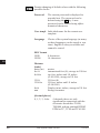
System
Version 2.4
0
180
TCA
1000Z01
USER MANUAL
English
CO
IN
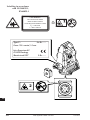
Congratulations on your purchase of a
TPS - System 1000.
ID
PM
FS
SC
OC
IO
AR
RC
EG
CA
CT
BC
DF
This manual contains important safety directions (refer
to chapter "Safety directions") as well as instructions
for setting up the instrument and operating it.
Read carefully through the User Manual before you
switch on the instrument.
SD
TS
IX
2
TPS-System 1000-2.4.0en
© Leica
Leica TPS - System 1000
System
CO
IN
Electronic theodolites and total stations
ID
PM
FS
SC
OC
IO
AR
RC
EG
CA
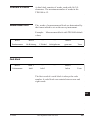
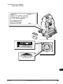
Product identification The instrument model and the serial number of your
product are indicated on the label in the battery
compartment.
Enter the model and serial number in your manual and
always refer to this information when you need to
contact your agency or authorized service workshop.
CT
BC
DF
Type: ___________
Serial number: ___________
SD
TS
IX
© Leica
TPS-System 1000-2.4.0en
3
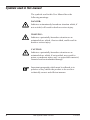
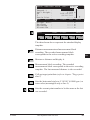
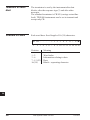
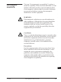
Symbols used in this manual
The symbols used in this User Manual have the
following meanings:
CO
IN
DANGER:
Indicates an imminently hazardous situation which, if
not avoided, will result in death or serious injury.
ID
PM
WARNING:
Indicates a potentially hazardous situation or an
unintended use which, if not avoided, could result in
death or serious injury.
FS
SC
OC
CAUTION:
Indicates a potentially hazardous situation or an
unintended use which, if not avoided, may result in
minor or moderate injury and / or appreciable material,
financial and environmental damage.
IO
AR
RC
Important paragraphs which must be adhered to in
practice as they enable the product to be used in a
technically correct and efficient manner.
EG
CA
CT
BC
DF
SD
TS
IX
4
TPS-System 1000-2.4.0en
© Leica
Leica TPS-System 1000 Registration Card
Part 1
This card comprises two parts:
- Retain part 1 for your records
- Return part 2 to Leica Geosystems AG, CH-9435
Heerbrugg, Switzerland - Your name and address, the
serial number of the instrument will be registered and
you will receive confirmation of this registration. Your local Leica representative will also receive
confirmation
CO
IN
ID
PM
FS
Act immediately
SC
Complete and return part 2 to ensure that you receive
software support. If you do not, you will not be
registered and Leica will not be able to provide the
support that you may need.
OC
IO
Software support
AR
Once your name, your address and the serial number of
RC
the instrument are registered Leica will, at its discretion,
provide you with the following support free of charge:
EG
- Instructions about any corrections and/or
modifications that are necessary for the correct
functioning of the software as supplied to you.
- Disks containing corrections and/or modifications
necessary for the correct functioning of the software
as supplied to you.
CA
CT
BC
DF
SD
TS
IX
© Leica
TPS-System 1000-2.4.0en
5
Limit to software support
Once your name, address and instrument are registered
Leica undertakes to provide reasonable support for the
software as supplied to you. This software support does
NOT extend to upgrades to new versions of software as
may be introduced by Leica in the future.
CO
IN
ID
Upgrade, enhancement, and exchange programs
PM
Only registered users will receive automatic notification
of possible future product enhancements.
FS
Change of address
SC
Should you change your address after registering for
software support, please write to Leica Geosystems AG,
CH-9435 Heerbrugg, Switzerland,
fax no +41 71 727 46 73, giving details of your new
address, telephone and telefax numbers.
OC
IO
AR
RC
EG
CA
CT
BC
DF
SD
TS
IX
6
TPS-System 1000-2.4.0en
© Leica
Part 2
Please fill in the coupon below and send the original or
a copy to the address on the other side or fax it to +41
71 727 3605.
CO
IN
ID
PM
FS
SC
OC
IO
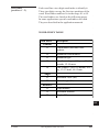
7
AR
Instrument type
Serial number
Date purchased
Company name / Address
(Please write clearly or use the Company stamp)
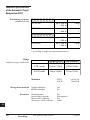
Software versions:
System SW
V
Standard programs:
Orientation
V
Resection
V
Stakeout
V
Tie distance
V
RC
EG
CA
CT
BC
DF
SD
TS
Contact persons
Telephone
Telefax
© Leica
IX
TPS-System 1000-2.4.0en
7
CO
IN
ID
PM
FS
SC
OC
IO
8
AR
RC
EG
CA
CT
BC
DF
Software-Support Registration
Leica Geosystems AG
CH-9435 Heerbrugg
Switzerland
SD
TS
IX
8
TPS-System 1000-2.4.0en
© Leica
View of chapters
© Leica
Contents
10 CO
Introduction
15 IN
Instrument descriptions
17 ID
Preparing to measure, setting up
22 PM
First steps
31 FS
System concept
37 SC
Operating concept
41 OC
Instrument operation
61 IO
Automatic Target Recognition
143 AR
RCS (Remote Controlled Surveying)
161 RC
Guide Light EGL1
173 EG
Checking and adjusting
175 CA
Care and transport
201 CT
Battery charging
203 BC
Data format
205 DF
Safety directions
219 SD
Technical specifications
240 TS
Index
249 IX
TPS-System 1000-2.4.0en
9
Contents
Introduction
CO
Area of applicability of this User Manual
15
16
IN
ID
PM
FS
Instrument descriptions
17
T - Version
TM - Version
TC - Version
TCM - Version
TCA - Version
17
18
19
20
21
Preparing to measure, setting up
SC
OC
IO
AR
RC
22
Unpacking
Charging battery
Preparing to measure
T- and TM - Versions
Preparing to measure with TC, TCM and
TCA - versions
Setting up the instrument
23
Tribrach with optical plummet
Tribrach without optical plummet
26
28
Laser plummet in instrument
22
23
25
26
29
EG
First steps
CA
Switching on the instrument
Levelling-up with the electronic bubble
Installing a distancer (EDM)
Measuring distances and angles
Summary of the first steps
CT
BC
DF
System concept
Software architecture
Memory concept and data flow
Operating modes
GeoBasic
SD
TS
31
31
32
33
35
36
37
37
38
39
40
IX
10
TPS-System 1000-2.4.0en
© Leica
Operating concept
Display / keyboard
Types of dialog
Program-selection dialog
Input/output dialog
Character field
Numeric field
List field
Two-value field
Heading
Time
Battery display
Graphical status icons
Function keys
Fixed keys
Control keys
Enter keys
Menu tree (Main menu after ON)
Instrument operation
Main menu
Fixed-key occupation in the main menu
Fixed-key occupation
Measurement & recording
Measuring distances and angles together
Measuring distances and angles separately
Target-point data
Remarks
Incrementing point numbers
Set and define prisms
Reduced input of ppm values
Comprehensive distance corrections (ppm)
Manual distance entry
Target eccentricity
Individual point number
Set station data
Select user template and measurement file
Station entry/setting
1-point orientation
41
42
43
43 CO
44
46
49 IN
50
52 ID
52
52
53
53
56
57
58
58
59
PM
FS
SC
OC
61 IO
61
AR
62
63
64 RC
67
68
70
71
72
73
75
76
79
80
81
82
EG
CA
CT
BC
DF
82
82 SD
88
TS
IX
© Leica
TPS-System 1000-2.4.0en
11
Data management
CO
91
91
92
92
Leica prisms and retro tapes
93
Prism for attachable EDM
Prism for incorporated EDM
The GRZ4 360° reflector
Leica retro tapes
Summary
Long distances
IN
ID
PM
Extra
On-line mode
Format a memory card
Remote-control mode
FS
SC
Configuration
System date and time
Define functionality
Interface parameters (GSI)
Interface parameters (GeoCOM)
Instrument identification
Auto-start configuration
System protection
User configurations
OC
IO
AR
Functions of the fixed keys
RC
Code information
Illumination
Electronic bubble
aF... - Additional functions
ON/OFF
EDM selection
EG
CA
90
Entering coordinates
Deleting data
View data
Edit data
93
94
95
96
97
97
98
99
100
101
102
104
105
107
108
109
110
111
113
124
124
126
128
129
141
142
CT
Automatic Target Recognition
BC
143
Functionality
144
Operation
146
Automatic Target Recognition ATR1 resolution
modes
152
Information on the use of Automatic Target
Recognition ATR1
156
DF
SD
Reduction of the range
Disturbance
TS
157
158
IX
12
TPS-System 1000-2.4.0en
© Leica
RCS (Remote Controlled Surveying)
Introduction
Setting up
Allocation of keys
Working procedure
Compass
Hz / V
Joystick
Lock interruption
Last point stored
161
161
163
166 CO
167
168
IN
170
171
172 ID
172
PM
Guide Light EGL1
ON / OFF
Checking and adjusting
Electronically
Compensator (electronic bubble)
V-index error
Line of sight
Tilting axis
Combined error determination
ATR1 collimation
Mechanically
Tripod
Bull's eye bubble on instrument
Bull's eye bubble on the tribrach
Optical plummet
173 FS
175 SC
175
177 OC
180
184 IO
188
191
191 AR
195
195 RC
196
196
EG
197
Laser plummet
199
Care and transport
201
Battery charging
203
Battery chargers GKL22 and GKL23
Battery chargers GKL12 and GKL14
Data format
Introduction
GSI storage format with 8 or 16 characters
Block concept
Code block
© Leica
173
TPS-System 1000-2.4.0en
203
204
205
CA
CT
BC
DF
SD
205
205 TS
206
207
IX
13
Structure of a block
Measurement block
Terminator of a data block
Structure of a word
CO
Word index (positions 1 - 2)
Information relating to data (positions 3 - 6)
Data (positions 7 - 15/23)
Separating character (position 16/24)
Block number
Units of measurement
IN
ID
Example of data format
PM
Safety directions
FS
Intended use of instrument
Limits of use
Responsibilities
Hazards of use
Laser classification
SC
OC
Integrated distancer (EDM)
Automatic target recognition (ATR1)
Guide light EGL1
Laser plummet
IO
AR
Electromagnetic acceptability
FCC statement (applicable in U.S.)
RC
EG
207
207
208
208
209
211
213
214
214
215
216
219
219
221
221
222
228
228
229
231
233
237
238
Product labeling
239
Technical specifications
240
Technical specifications of the Automatic Target
Recognition ATR1
244
Technical specifications of the EGL1 Guide
Light
245
Application programs
246
Atmospheric corrections
247
CA
CT
BC
DF
Index
249
SD
TS
IX
14
TPS-System 1000-2.4.0en
© Leica
Introduction
TPS 1000 stands for Tachymat, Theodolite or Total station
Positioning System and expresses the true integration of
computerization with total station technology. The system
offers more functionality and greater flexibility for a wider
variety of survey applications and yet improves user comfort
and productivity. The large display is positioned conveniently
under the telescope to give the user access to much more
information at a glance. The keyboard, with its function keys,
is easily understood and permits convenient input. Removable
data storage, the large battery capacity and on-board
application programs ensure that every available facility is
contained in one unit. The TPS1000 is ready for use as soon as
it is set up and turned on. No additional cabling to batteries or
data recorders is necessary. However, external data loggers,
computers or batteries can be connected.
CO
IN
ID
PM
FS
SC
All TPS1000 instruments are routinely supplied with a laser
plummet located in the vertical axis. The TPS1000 can
therefore be set up quickly and accurately over the ground
point with the help of the red laser dot. Computer industry
standards have been incorporated such as the removeable
PCMCIA card for data storage. The data structure is
compatible with previous and other current Leica total stations
and electronic theodolites.
This permits data interchangeability with Leica GPS - Systems.
Individual application programs are available or can be written
by the user.
OC
Motorized versions of the TPS-System 1000, and versions
equipped with the ATR1 automatic target recognition system,
ensure higher levels of productivity for repetitive pointing or
for stake out applications.
CA
IO
AR
RC
EG
CT
BC
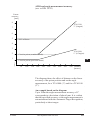
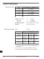
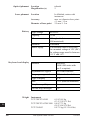
The TC2003/TCA2003 high-performance Total Station differs
considerably from other instruments of the TPS1000 family in
DF
some features. Three performance characteristics of the
TC2003/TCA2003 have changed
SD
Angle measurement accuracy
0.5" (0.15 mgon)
Distance measurement accuracy
1 mm + 1 ppm
Searching accuracy (TCA version)
TS
up to 200m
1 mm
(All specifications are standard deviations)
IX
© Leica
TPS-System 1000-2.4.0en
15
All instruments of the 2003 version are supplied with a
quality certificate.
As standard the application software"Monitoring" is
implemented in the TCA2003.
CO
The TC2003/TCA2003 instruments are equipped with a
special carrying handle. This handle is an integrated
part of the instrument and should always be fitted to the
instrument during measurements.
IN
ID
PM
Make sure that the carrying handle is carefully fitted to
the instrument and that the mounting screws are tighten.
FS
SC
OC
IO
AR
Area of applicability of
this User Manual
This manual applies to all TPS1000 instruments and to
the TC2003/TCA2003 instruments.
Differences between the various models are clearly set
out and assigned.
General text applies to all types.
RC
EG
General illustrations represent the TCA 1800
instrument with EGL1 guide light option and apply to
all models.
CA
CT
The present User Manual is valid for the software
version 2.2.
BC
DF
SD
TS
IX
16
TPS-System 1000-2.4.0en
© Leica
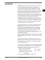
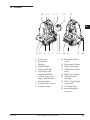
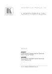
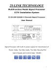
Instrument descriptions
CO
T - Version
IN
7,8
5 4
6
15 17
ID
PM
1000Z36
FS
SC
OC
IO
AR
9 10 12 11
3
2
16
13 1
14
RC
1
2
3
4
5
6
7
8
9
Footscrew
Keyboard
Display
Optical sight
Carrying handle
Telescope
Vertical drive screw
Vertical clamp
Horizontal drive screw
10 Horizontal clamp
11 Battery housing
12 Tribrach securing
knob
13 Bull's-eye bubble
14 Memory card
housing
15 Focusing ring
16 Interchangeable
eyepiece
17 Adapter for attaching
EDM
EG
CA
CT
BC
DF
SD
TS
IX
© Leica
TPS-System 1000-2.4.0en
17
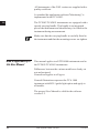
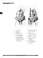
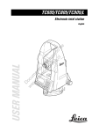
TM - Version
CO
7
5 4
9
12 11
6
15 17
IN
1000Z26
ID
PM
FS
SC
OC
IO
AR
1
2
3
4
5
6
7
9
RC
EG
CA
3
2
Footscrew
Keyboard
Display
Optical sight
Carrying handle
Telescope
Vertical drive screw
Horizontal drive screw
CT
BC
16 13 1
14
11 Battery housing
12 Tribrach securing
knob
13 Circular level
14 Memory card
housing
15 Focusing ring
16 Interchangeable
eyepiece
17 Adapter for attaching
EDM
DF
SD
TS
IX
18
TPS-System 1000-2.4.0en
© Leica
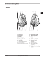
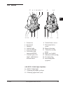
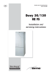
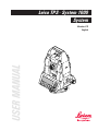
TC - Version
16
4 5
6
7
17
12
CO
IN
1000Z02
ID
PM
FS
SC
OC
15 13
1
3
2
9 8
1
2
3
4
5
6
Footscrew
Keyboard
Display
Optical sight
Carrying handle
Telescope with
integrated EDM
7 Coaxial optics for
angle- and distance
measurement
8 Vertical drive screw
9 Vertical clamp
18
14
11
10 IO
10 Horizontal drive
screw
11 Horizontal clamp
12 Battery housing
13 Tribrach securing
knob
14 Bull's-eye bubble
15 Memory card
housing
16 EGL1 Guide light
(optional)
17 Focusing ring
18 Interchangeable
eyepiece
AR
RC
EG
CA
CT
BC
DF
SD
TS
IX
© Leica
TPS-System 1000-2.4.0en
19
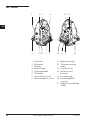
TCM - Version
CO
4 5
6
7
8
3
2
9
9 10 11
14
IN
1000Z27
ID
PM
FS
SC
OC
13
IO
1
12 15
AR
1
2
3
4
5
6
Footscrew
Keyboard
Display
Optical sight
Carrying handle
Telescope with
integrated EDM
7 Coaxial optics for
angle- and distance
measurement
RC
EG
CA
CT
BC
8 Vertical drive screw
9 Horizontal drive
screw
10 Battery housing
11 Tribrach securing
knob
12 Bull's-eye bubble
13 Memory card
housing
14 Focusing ring
15 Interchangeable
eyepiece
DF
SD
TS
IX
20
TPS-System 1000-2.4.0en
© Leica
TCA - Version
17
8
4 5 18 6/16 7
14
CO
IN
1000Z28
ID
PM
FS
SC
OC
13 11
1
3
2
1
2
3
4
5
6
Footscrew
Keyboard
Display
Optical sight
Carrying handle
Telescope with
integrated EDM
7 Coaxial optics for
angle- and distance
measurement
9 10
12
15 IO
8 Vertical drive screw
9 Horizontal drive
screw
10 Battery housing
11 Tribrach securing
knob
12 Bull's-eye bubble
13 Memory card housing
14 Focusing ring
15 Interchangeable
eyepiece
AR
RC
EG
CA
CT
BC
DF
with EGL1 Guide light (Option):
16 EGL1 Guide light
17 Flashing left diode (yellow)
18 Flashing right diode (red)
SD
TS
IX
© Leica
TPS-System 1000-2.4.0en
21
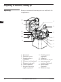
Preparing to measure, setting up
CO
Unpacking
Remove instrument from transport case and check for
completeness:
IN
13
PM
1000Z04
ID
3
2
FS
4
SC
12
OC
5
11
IO
10
1
AR
9
6
7
RC
8
EG
CA
1 Instrument
2 Protective cover
3 Focusing sleeve
(optional)
4 Memory card (optional)
5 Plummet (optional)
6 Cable (optional)
7 Eyepiece for steep
angles (optional)
CT
BC
DF
SD
8 Zenith eyepiece
(optional)
9 Allen key
10 Screwdriver, set pin
11 Interchangeable
eyepiece (optional)
12 Spare battery
(optional)
13 Shoulder straps
TS
IX
22
TPS-System 1000-2.4.0en
© Leica
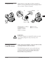
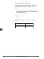
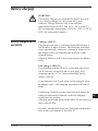
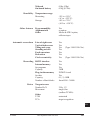
Charging battery
Charge batteries using GKL12, GKL14, GKL22 or
GKL23. For more information about charging batteries
refer to chapter "Battery charging".
CO
IN
/
ID
PM
1000QS09
GEB87
FS
GKL23 ( )
GKL23-1 ( )
SC
GEB87
OC
Charging time: 1.5 hours
External batteries:
GEB70: 1.5 hours
GEB71: 5.0 hours
230V ±10%
115V +10/-20%
IO
AR
RC
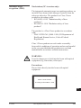
WARNING:
The battery chargers are intended for indoor use only.
Use a battery charger in a dry room only, never
outdoors.
EG
CA
CT
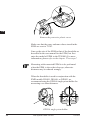
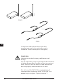
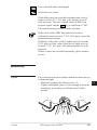
Preparing to measure
T- and TM - Versions
Before using the theodolite version for the first time,
certain precautions need to be taken:
The black plastic protective cover on the telescope
connector should be removed with a knife blade or
screwdriver before fitting the EDM (=Electronic
Distance Measuring instrument).
BC
DF
SD
TS
IX
© Leica
TPS-System 1000-2.4.0en
23
CO
IN
1000Z029
ID
PM
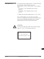
Remove the protective plastic cover
FS
SC
Make sure that the ppm- and mm-values stored in the
EDM are reset to "0.00".
OC
Line up the axis of the EDM to that of the theodolite as
described in the user manual for the EDM, but first
enter the model of EDM in the TPS1000. For more
information, please refer to the chapter "First steps".
IO
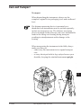
AR
Measuring with connected EDM is to be performed
when the EDM is above the telescope, otherwise
distances may be reduced wrongly.
RC
EG
CA
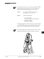
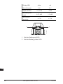
When the theodolite is used in conjunction with the
EMD models DI1001, DI1600, or DI2002, we
recommend using the GPH1A single-prism holder for
measuring over short distances.
CT
BC
1000Z024
DF
SD
TS
GPH1A single-prism holder
IX
24
TPS-System 1000-2.4.0en
© Leica
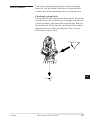
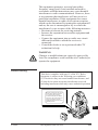
The height difference between the telescope's optical
axis and the infra-red beam is corrected by the
corresponding difference at the target, therefore aim the
crosshairs at the yellow target mark.
CO
IN
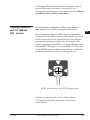
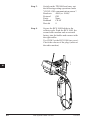
Preparing to measure
with TC, TCM and
TCA - versions
ID
For instruments with built-in EDM, no preliminary
adjustments to the EDM are required before use.
PM
We recommend using the GPH1 single-prism holder.
The intersection of the vertices of the prism lies exactly FS
at the intersection of the rotation axes of the reflector
and can therefore be used directly as the target. For
SC
perfect targeting of the GPH1 over longer distances the
additional GZT4 target is recommended. The telescope
of the EDM is adjusted during manufacture so that the OC
measuring beam lies exactly on the optical axis.
IO
AR
RC
TC600Z11
EG
CA
CT
BC
GPH1 prism holder with GZT4 target plate
DF
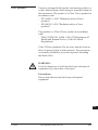
Aim the crosshairs at the centre of the reflector.
TCA models can target the centre of the prism
automatically.
SD
TS
IX
© Leica
TPS-System 1000-2.4.0en
25
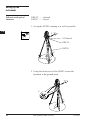
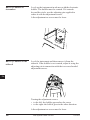
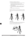
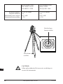
Setting up the
instrument
CO
IN
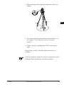
Tribrach with optical
plummet
ID
GDF 22 ........ tribrach
GST20 ......... tripod
1. Set up the GST20, centring it as well as possible.
PM
1
FS
5/8"thread
SC
GDF 22
OC
GST20
2
2
1
2
AR
1000Z05
IO
RC
EG
2. Using the footscrews of the GDF22, centre the
plummet to the ground point.
CA
CT
BC
3
DF
1000Z06
SD
TS
IX
26
TPS-System 1000-2.4.0en
© Leica
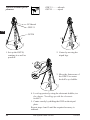
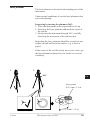
3. Move the legs of the tripod to centre the bull’s-eye
bubble.
CO
IN
5
ID
4
4
PM
FS
1000Z07
4
SC
OC
4. Level-up precisely, using the electronic bubble (see
the chapter "Levelling-up with the electronic
bubble").
5. Centre exactly by shifting the GDF on the tripod
plate.
IO
AR
RC
EG
Repeat steps 4 and 5 until the required accuracy is
reached.
CA
The laser plummet cannot be used in conjunction with a CT
tribrach which already has an optical plummet.
BC
DF
SD
TS
IX
© Leica
TPS-System 1000-2.4.0en
27
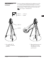
GDF 21 ........ tribrach
GST20 ......... tripod
Tribrach without optical
plummet
CO
IN
5/8"thread
ID
GDF 21
PM
GST20
FS
2
2
1
2
1000Z09
1
1000Z08
1
SC
OC
IO
AR
1. Set up the GST20,
centring it as well as
possible.
2. Centre by moving the
tripod legs.
4
RC
EG
CA
3
3. Move the footscrews of
the GDF21 to centre
the bull’s-eye bubble.
1000Z10
CT
BC
DF
4. Level-up precisely, using the electronic bubble (see
the chapter "Levelling-up with the electronic
bubble").
5. Centre exactly by shifting the GDF on the tripod
plate.
Repeat steps 4 and 5 until the required accuracy is
attained.
SD
TS
IX
28
TPS-System 1000-2.4.0en
© Leica
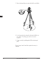
Laser plummet in
instrument
The laser plummet is built into the standing axis of the
"L" versions of the TPS1000 instruments. A red dot
projected on the ground makes it much easier to centre
the instruments. The laser plummet is activated with
(see chapter "Illumination").
CO
IN
ID
GDF 21 ........ tribrach
GST20 ......... tripod
PM
FS
SC
OC
GDF 21
IO
GST20
AR
1000Z37
1000Z38
RC
EG
CA
CT
BC
1. Set up the GST20,
centring it as well as
possible.
2. Move the footscrews of
the GDF21 to centre
DF
the plummet over the
ground point.
SD
TS
IX
© Leica
TPS-System 1000-2.4.0en
29
3. Move the tripod legs to centre the bull’s-eye bubble.
CO
IN
ID
PM
FS
1000Z39
SC
OC
IO
AR
RC
4. Level-up precisely, using the electronic bubble (see
the chapter "Levelling-up with the electronic
bubble").
EG
CA
5. Centre exactly by shifting the GDF on the tripod
plate.
CT
BC
Repeat steps 4 and 5 until the required accuracy is
attained.
DF
SD
TS
IX
30
TPS-System 1000-2.4.0en
© Leica
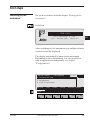
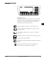
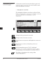
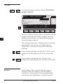
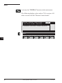
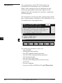
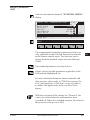
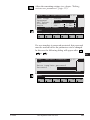
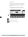
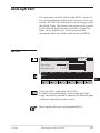
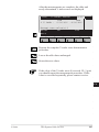
First steps
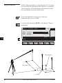
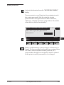
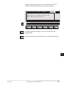
Switching on the
instrument
CO
Set up in accordance with the chapter "Setting up the
instrument".
IN
Switch on.
ID
PM
TCA 1800
FS
GSI-Version 2.22a
<C> Leica AG, 1994-97
SC
After switching on, the instrument type and the software OC
version are briefly displayed.
IO
The display automatically jumps to the main menu.
Depending on the configuration, it is also possible to
start an application automatically (see chapter
"Configuration").
AR
RC
EG
14:03
MAIN MENU : PROGRAMS
1
2
3
4
CA
Orientation
Resection
Stakeout
Tie Distance
EXTRA
CAL
CT
CONF
DATA
BC
SETUP MEAS
HELP
DF
F1
F2
F3
F4
F5
F6
SD
TS
IX
© Leica
TPS-System 1000-2.4.0en
31
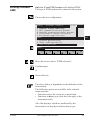
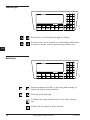
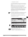
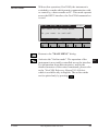
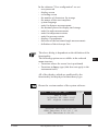
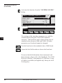
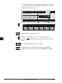
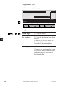
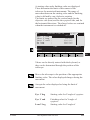
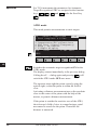
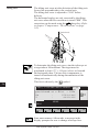
Show on-line HELP information for the main menu.
On-line HELP information is available for all dialogs.
14:03
HELP
Select application program from
menu using the arrow keys up
and down and confirm with CONT
or ENTER, or press the number
key shown in front of
MAIN MENU : PROGRAMS
CO
IN
ID
END
F1
PM
FS
F2
F3
F4
F5
F6
Leave the HELP screen and return to the main menu.
SC
OC
IO
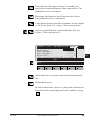
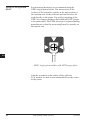
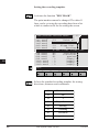
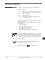
Levelling-up with the
electronic bubble
Graphical and numerical display of the longitudinal and
transverse tilt of the instrument’s vertical axis.
AR
RC
14:03
ELECT. BUBBLE
EG
Tilt L
: 0°00'10"
Tilt T
: 0°00'00"
CA
HELP
CT
F1
F2
F3
F4
F5
F6
BC
DF
Using the footscrews, the instrument can be levelled-up
without having to turn it through 90° (100 gon) or 180°
(200 gon).
In the display which is closest to the bull's-eye bubble,
the movement of the small circle runs parallel to the
movement of the bubble in the alhidade. The other
display shows the movement in the opposite direction.
SD
TS
IX
32
TPS-System 1000-2.4.0en
© Leica
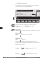
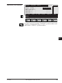
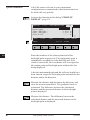
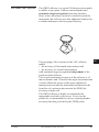
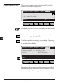
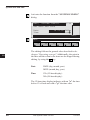
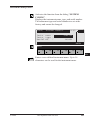
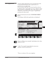
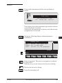
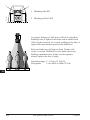
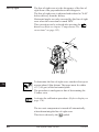
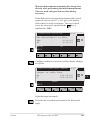
Installing a distancer
(EDM)
Only for T- and TM-Versions with attached EDM:
The type of EDM used must be entered in the system.
CO
Choose the user configuration.
IN
14:03
SYSTEM CONFIG.
System date and time
Define functionality
GSI communications param.
GeoCOM communications param.
Instrument identification
Autoexec-application
CONF\
1
2
3
4
5
6
ID
PM
INFO
FS
7 System protection
8 User configuration
9 EDM selection
SC
HELP
F1
OC
F2
F3
F4
F5
F6
IO
AR
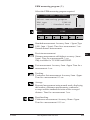
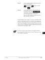
Move the inverse bar to "EDM selection".
Confirm input
RC
or
EG
choose directly.
CA
CT
The above dialog is dependent on the definition of the
functionality.
The following options are available in the reduced
menu structure:
• Functions where the cursor bar is positioned
• Functions in heavy type (this does not apply to the
instrument itself).
All of the displays which are unaffected by the
functionality are displayed without heavy type.
BC
DF
SD
TS
IX
© Leica
TPS-System 1000-2.4.0en
33
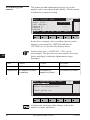
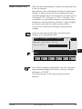
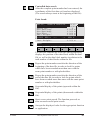
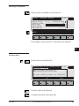
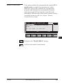
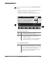
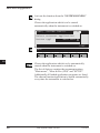
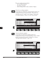
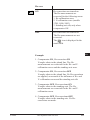
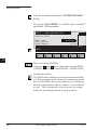
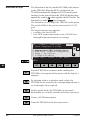
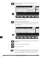
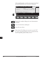
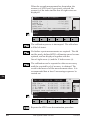
The appropriate distancer can be selected from the
following dialog.
CONF\
CO
14:03
EDM SELECTION
Select EDM
EDM type
:
EDM offset :
Wavelength :
IN
DI1001
40.9mm
850nm
LIST
ID
HELP
PM
F1
FS
F2
F3
F4
F5
F6
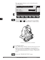
Choose from the EDM list.
Using the
and -keys, choose the relevant EDM:
( DI3002 = DIOR3002 and DI3002S = DIOR 3002S )
SC
OC
IO
AR
RC
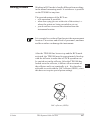
1000Z34
EG
CA
CT
T-Version with distancer DI1600
BC
Confirm the choice.
The "EDM offset" (distance between telescope axis and
EDM axis) and the wavelength are automatically set.
The correction of the EDM offset can be turned on and
off in the option target point (see chapter "Target-point
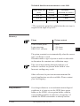
data").
DF
SD
TS
Leaves the "EDM SELECTION" menu.
IX
34
TPS-System 1000-2.4.0en
© Leica
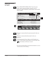
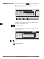
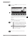
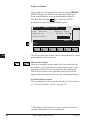
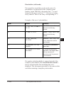
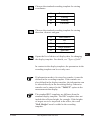
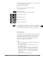
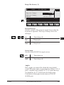
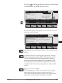
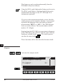
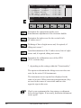
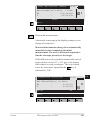
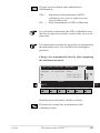
Measuring distances
and angles
Select "MEASURE MODE (GSI)" from the main
menu. In the measuring dialog, distances can be
measured, angles displayed, point numbers entered and
data recorded.
MEAS\ MEASURE MODE (GSI) 14:03
Point no. :
1
Remark 1
:
----Refl.Height :
0.000 m
I
Hz
:
295°22'40"
V
:
91°20'30"
Horiz.Dist. :
37.127 m
ALL
DIST
REC TARGT Hz0 αNUM
Height diff :
Easting
:
Northing
:
Elevation :
HELP
F1
-0.870
554.386
-873.330
13.227
LAST
F2
F3
F4
ID
PM
FS
OC
PROG
F5
IN
SC
m
m
m
m
I<>II
CO
IO
F6
AR
RC
Distance is measured and current measured values are
stored.
EG
Distance is measured and measured values are
displayed.
CA
Current measured values (shown on the display) are
stored. If the distance measurement was activated with
, the distance will also be stored.
CT
The measurement dialog is described in detail in section
"Measurement & Recording".
DF
BC
SD
TS
IX
© Leica
TPS-System 1000-2.4.0en
35
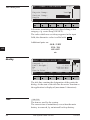
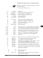
Summary of the first
steps
Step 1:
Set up the instrument and level-up using
the bull's-eye bubble.
Step 2:
Switch on ( the instrument display shows
the main menu ).
Step 3:
Show HELP information for the main
menu.
FS
Step 4:
Leave the HELP screen and return to the
main menu.
SC
Step 5:
Adjusting the electronic bubble.
OC
Step 6:
For T- and TM-version only:
In the system, select the EDM used with the
theodolite.
Step 7:
Select measure mode directly from main
menu.
Step 8:
Target the prism and start a distance
measurement. Once measured, the horizontal distance is displayed on the bottom line.
CO
IN
ID
PM
IO
AR
RC
EG
CA
Measuring with connected EDM (T- and TM-versions)
is to be performed only when the EDM is above the
telescope, otherwise distances may be reduced wrongly.
CT
BC
DF
SD
TS
IX
36
TPS-System 1000-2.4.0en
© Leica
System concept
The TPS1000 series includes many different
instruments: electronic theodolites and total stations of
various accuracy classes, with or without motorization,
and total stations with automatic targeting.
CO
IN
ID
All of these models use the same software architecture
and the same concept for data storage and data flow.
PM
FS
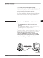
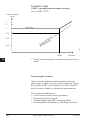
Software architecture
SC
The software of the TPS1000 can be divided into two
groups:
• The system software, which covers the basic
functions
• The applications software, which supports surveyspecific applications and procedures.
OC
IO
AR
The system software forms a coherent unit, whereas the
applications software can be compiled in accordance
RC
with the individual requirements of the user.
Using the "workbench" provided, both the system
EG
software and the applications software can be loaded
across the serial interface by the user, who is in a
CA
position to install improved software versions.
CT
System software,
applications
1000Z53
BC
DF
SD
TS
Workbench
© Leica
TPS-System 1000-2.4.0en
37
IX
The software permits up to three languages to remain
stored simultaneously and one of them to be selected.
The range of language versions available is constantly
being expanded. If you need a particular language
version, please ask your agency about its availability.
CO
IN
ID
PM
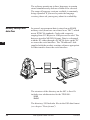
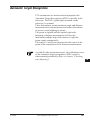
Memory concept and
data flow
FS
SC
OC
In general, measurement data is stored on an SRAM
memory card (from here on referred to as "MC") which
meets PCMCIA standards. Cards with a capacity
ranging from 512 Kbytes to 4 Mbytes can be used. The
data are stored in MS-DOS format. Data is exchanged
with the PC either through a PCMCIA drive on the PC
or across the serial interface. The "Workbench" disk
supplied with the product contains software appropriate
for data transfer across the serial interface.
IO
1000Z54
AR
RC
EG
CA
CT
BC
The structure of the directory on the MC is fixed. It
includes two subdirectories for the TPS1000:
\GSI
\LOG
DF
SD
The directory \GSI includes files in the GSI data format
(see chapter "Data format").
TS
IX
38
TPS-System 1000-2.4.0en
© Leica
A distinction is made between:
• Input data, generally fixed-point coordinates
• Output data, generally measurements, coordinates, or
derived values relating to "new points".
It is advisable to store the input and output data in two
separate files, although it is possible to store them
together in a single file.
A maximum of 24 files can be managed. Twelve of
them already have permanent names (FILE01.GSI to
FILE12.GSI) and are used primarily to store
measurement data (measurement files). The remaining
twelve files can be given any name, but this must
always terminate with GSI (e.g. PROJ2563.GSI). It is
useful to store the fixed-point coordinates in these files
(data files).
CO
IN
ID
PM
FS
SC
In the directory \LOG, additional data from most of the
OC
loadable applications can be stored in a protocol file.
Instead of using the MC, the data can be output in GSI
format at the serial data interface.
IO
AR
When data storage is performed across the serial
interface, no data from the applications is output into
the protocol file. Fixed-point coordinates can be read
only from the MC.
RC
EG
CA
CT
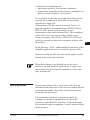
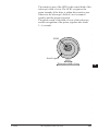
Operating modes
Normal operation involves an observer who keys-in
information and who moves the telescope and points the BC
instrument manually. The results of the measurement
are displayed and stored.
DF
The instrument can also be operated partially by
SD
sending user-defined commands across the serial
interface (reduced RS232 interface). If the instrument
has automatic target recognition, it can be operated fully TS
in this manner.
IX
© Leica
TPS-System 1000-2.4.0en
39
1000Z55
CO
IN
ID
PM
Two sets of commands are available for controlling the
instrument:
FS
• The GSI command set has a simple structure and so
can be easily learned. It is particularly suitable for
use in external data-recording instruments. It
contains control commands which are adequate for
simple applications in conjunction with motorized
instruments and with instruments having automatic
target recognition (ATR). For more information,
please refer to "WILD Instruments On-Line"
(document no. G-366-0en), a copy of which is
available (in English only) from your local Leica
agency.
SC
OC
IO
AR
RC
• The GeoCOM command set governs complex
operations in the TPS1000 instruments and is to be
preferred for the professional development of control
programs. For more information, please refer to
"GeoCOM Reference Manual" (document no. G560-0en), a copy of which is available (in English
only) from your local Leica agency.
EG
CA
CT
BC
DF
GeoBasic
SD
TS
IX
40
The GeoBasic development environment permits the
professional development of additional applications for
the TPS1000. For more information, please refer to
"GeoBasic Compiler and Keyboard Simulator", a copy
of which is available (in English only) from your local
Leica agency.
TPS-System 1000-2.4.0en
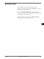
© Leica
Operating concept
The TPS1000 system is organized into various
CO
functions, which are started via the function keys in the
main menu or via the hard keys.
IN
The use of loadable applications can meet specific
user requirements, which are then called up from the list ID
of applications in the main menu.
PM
Each application or function is divided into dialogs
which include interrelated information.
FS
SC
OC
BK
IO
AR
RC
EG
CA
CT
BC
DF
SD
TS
IX
© Leica
TPS-System 1000-2.4.0en
41
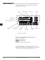
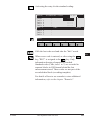
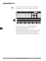
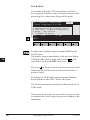
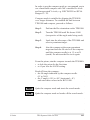
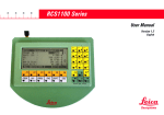
Display / keyboard
The display and the keyboard are divided into specific
areas, making the layout clear and the operational
procedure easy to learn.
CO
IN
Time
Battery display
Status icons
Input keys
ID
PM
Heading
FS
MAIN MENU : PROGRAMS
1 Orientation
2 Resection
3 Stakeout
4 Tie Distance
5 Free Station
6 Sets of Angles
EXTRA
CAL
CONF DATA
Dialog area
Function key assignment
SC
F1
F2
F3
CODE
OC
BK
SETUP MEAS
F4
aF...
7
8
9
4
5
6
1
2
3
0
• +/-
14:03
F5
CONT
F6
Shift CE
ON
OFF
ESC
IO
Cursor bar
AR
RC
Illumination *
Electronic
bubble*
Other
functions *
Running
info-bar
Control keys
* => always accessible !
EG
The four colour groupings for the keys are:
White: Fixed keys
Orange: Function keys
Green: Control keys
Yellow: Numeric and entry keys
CA
CT
BC
The graphical display is arranged with 8 lines of 35
characters. Graphics can be displayed with a resolution
of 64 x 210 pixels across the full display area.
DF
SD
TS
IX
42
TPS-System 1000-2.4.0en
© Leica
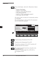
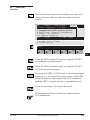
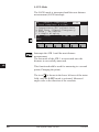
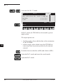
Types of dialog
To give an overall view, several types of dialog are
used. The input procedure is the same within all types
of dialog, promoting ease in use. The following
examples illustrate the types of dialog used in the
TPS1000.
CO
IN
ID
Program-selection dialog
PM
1
2
3
4
14:03
MAIN MENU : PROGRAMS
Orientation
Resection
Stakeout
Tie Distance
EXTRA
F1
CAL
F2
CONF
FS
SC
DATA
F3
F4
SETUP MEAS
F5
F6
OC
BK
IO
To start the program "Resection", the cursor bar is
to the
,
moved by means of the arrowed keys
appropriate field and is started with
AR
RC
or
or
EG
the function is called directly.
CA
CT
BC
DF
SD
TS
IX
© Leica
TPS-System 1000-2.4.0en
43
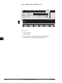
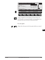
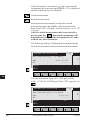
Input/output dialog
CO
MEAS\ MEASURE MODE (GSI) 14:03
1
----0.000 m
I
295°22'40"
91°20'30"
----- m
ALL
DIST
REC TARGT Hz0 αNUM
Point no. :
Remark 1
:
Refl.Height :
Hz
:
V
:
Horiz.Dist. :
IN
ID
PM
F1
F2
F3
F4
F5
F6
FS
The dialog mostly consists of several display fields. To
enter a value, the cursor bar must be moved to the
appropriate field (e.g. "Point no.").
SC
OC
BK
If the entry is concluded with
IO
the cursor bar can
then be moved to another input field (e.g. Refl. Height)
for entering this value.
If the entry field is closed with
, this concludes
the input and generally also quits the dialog. All values
entered are accepted.
AR
RC
The cursor bar cannot be moved within a field used
exclusively for output. The values in that field (e.g.
measurements such as "Hz" and "V") cannot be
changed.
EG
CA
CT
This rejects the entries made in a dialog field and
returns it to its condition before it was called. In general
there is a simultaneous jump back to the previous
dialog.
BC
DF
SD
TS
IX
44
TPS-System 1000-2.4.0en
© Leica
Fields in the input dialog
The input of all sorts of information is supported by
several types of input fields. The input procedure is the
same within all types of dialog, promoting ease in use. CO
If the type of input field is not clear, it can be identified
IN
from the assignation of the key
.
The examples below illustrate the types of field used in
ID
the TPS1000.
PM
FS
SC
OC
BK
IO
AR
RC
EG
CA
CT
BC
DF
SD
TS
IX
© Leica
TPS-System 1000-2.4.0en
45
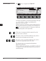
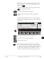
αNUM".
-key is assigned with "α
The
Character field
CO
MEAS\ MEASURE MODE (GSI) 14:03
1
----0.000 m
I
295°22'40"
91°20'30"
----- m
ALL
DIST
REC TARGT Hz0 αNUM
Point no. :
Remark 1
:
Refl.Height :
Hz
:
V
:
Horiz.Dist. :
IN
ID
PM
F1
F2
F3
F4
F5
F6
FS
All entries not subject to restrictions belong to this type,
e.g. point numbers, coding. Any alphanumeric
characters can be entered.
Numeric values are entered by means of the input keys,
the rest of the characters by means of the function key
. The maximum number of characters which can
be entered depends on the input field.
SC
OC
BK
IO
AR
...
RC
If the entry is commenced with a numeric key, the
previous value is deleted.
The preset value is not deleted and the entry mark is
located at the left-hand end of the field.
EG
CA
/
CT
The preset value is not deleted and the entry mark is
located at the right-hand end of the field.
The function keys are assigned with alphabetic
characters in all cases.
With an additional function key an alphabetic character
is assigned to each individual function key and can be
selected directly.
BC
DF
SD
TS
IX
46
TPS-System 1000-2.4.0en
© Leica
14:03
CO
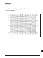
ABCDE FGHIJ KLMNO PQRST UVWXY Z[\]
F1
F4
F3
F2
IN
F6
F5
ID
PM
The following display appears:
FS
14:03
SC
OC
BK
A
B
C
D
E
INS
IO
F1
F2
F3
F4
F5
F6
AR
to
are now assigned individual characters which can be
chosen.
RC
EG
Additionally, the
control keys can be used to
and
select the complete ASCII character set a block at a
CA
time.
Possible blocks of characters:
CT
ABCDE FGHIJ KLMNO PQRST UVWXY Z[\]
BC
abcde fghij klmno pqrst uvwxy z{|}
Çüéâä àåçêë èïîìÄ ÅÉæÆô öòûùÿ ÖÜ¢£
áíóúñ Ñao¿
DF
¬½¼I« »@ˆ_` ˜ ¥Ptƒ
αβΓπ∑ σμτϕθ Ωδ∞Φε ∩≡±≥≤ ÷ ≈ ° • • √n²
SD
!"#$% &’()* +,-./ :;<=> ?
TS
F1
F2
F3
F4
F5
F6
IX
© Leica
TPS-System 1000-2.4.0en
47
• Insert mode
If the entry mark is at the right-hand end of the input
field, the new character will be appended to the existing
one.
If the entry mark is at another position in the input field,
the character will be written over.
CO
IN
"INS" is assigned to the
-key if a function key
was previously used to select an alphanumeric block.
and
The
control keys can be used to move the
entry mark over a digit or character before which a
character can now be inserted. The character is always
inserted before the cursor.
ID
PM
FS
SC
In a numeric field the insert mode is also called with
. The insert mode remains active until it is
deactivated with
or until quitting the field.
OC
BK
IO
AR
RC
EG
CA
CT
BC
DF
SD
TS
IX
48
TPS-System 1000-2.4.0en
© Leica
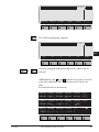
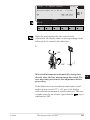
The
Numeric field
-key is assigned with "EDIT".
CO
MEAS\ MEASURE MODE (GSI) 14:03
Point no. :
1
Remark 1
:
----Refl.Height :
1.500 m
Hz
:
286°55'50"
V
:
91°16'20"
Horiz.Dist. :
----- m
ALL
DIST
REC TARGT Hz0 EDIT
F1
F2
F3
F4
F5
IN
ID
F6
PM
FS
All entries requiring numeric input (e.g. point
coordinates) are of this type. The permitted number of
digits, the decimal place etc. are all assigned
automatically, and the units used are indicated.
...
If the entry is commenced with a numeric key, the
previous value is erased.
OC
BK
IO
The previous value is not erased and the entry mark is
located at the left-hand end of the field.
/
SC
The previous value is not erased and the entry mark is
located at the right-hand end of the field.
AR
RC
EG
CA
Some numeric fields permit input only at a preset
interval. Deviations from this interval provoke an
acoustic signal and the value is set to the minimum or
maximum value.
CT
BC
DF
SD
TS
IX
© Leica
TPS-System 1000-2.4.0en
49
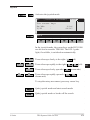
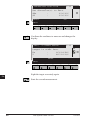
List field
-key when the symbol
"LIST" is assigned to the
is shown at the end of a line. Open a list field to
select parameters from it.
CO
SETUP\ START-UP DISPLAY 14:03
Select user template & files
User templ. :Polar(Standard)
Rec. device :
Memory Card
Meas. file :1 √ FILE01.GSI
Data file :2 √ FILE02.GSI
IN
ID
PM
QSET
F1
FS
SC
F2
F3
F4
STN
LIST
F5
F6
All entries which permit only a certain input belong to
this type, e.g. the name of a file.
OC
BK
Open the list field.
IO
The following display shows a typical example for an
opened list field:
AR
SETUP\ START-UP DISPLAY 14:03
Select user
User templ. Polar (Standard)
Cartesian
Rec. device
Meas. file
Polar+cartesian
Data file
User 4
RC
EG
CA
CT
Selects.
BC
Confirm selection.
DF
SD
TS
IX
50
TPS-System 1000-2.4.0en
© Leica
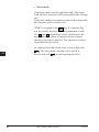
In numeric list fields, and in some alphanumeric ones,
an entry can be called directly by keying-in the value
instead of using
.
CO
CONF\ GSI COMMUNICATION 14:03
Set GSI com 1
19200
Baud rate
9600
Protocol
Parity
4800
Terminator
2400
Data bits
IN
ID
PM
Example:
Keying-in "1" marks the baud rate (19200)
FS
The entry is concluded with
SC
.
OC
BK
IO
In alphanumeric list fields the entry can be chosen
quickly using the accompanying number tag.
AR
CONF\ DEFINE RECORD MASK 14:03
User templ. 2
21
Hz
1st word
32
Horiz.Dist
2nd word
3rd word
33
Height diff
4th word
52
n / s
5th word
RC
EG
CA
CT
Example:
Keying-in "2" marks "Hz".
The entry is concluded with
BC
.
DF
SD
TS
IX
© Leica
TPS-System 1000-2.4.0en
51
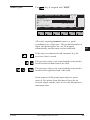
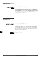
Two-value field
CO
aF...\BEEP / HZ-SECTOR
14:03
Set Beep and Hz-sector
Keystr.Beep :
loud
Sector Beep :
Angle
:
OFF
90°00'00"
ON
IN
F1
F2
F3
F4
F5
F6
ID
FS
All entries permitting only two values belong to this
category, e.g. sector beep (ON/OFF).
The value which was set always appears in the input
.
field; the alternative value is called with
SC
Additional pairs are:
PM
OLD / NEW
YES / NO
ON/ OFF
etc.
OC
BK
IO
AR
Heading
MEAS\ MEASURE MODE (GSI) 14:03
Point no. :
Remark 1
:
Refl.Height :
Hz
:
V
:
Horiz.Dist. :
RC
EG
ALL
CA
DIST
F1
CT
F2
1
----0.000 m
295°22'40"
91°20'30"
----- m
REC
F3
TARGT
F4
Hz0
I
αNUM
F5
F6
The title line contains the designation of the particular
dialog. At the start of the title line the active function or
the application is displayed (maximum 5 characters).
BC
DF
SD
Time
14:03
The time as used by the system.
The correct time is maintained, even when the main
battery is removed, by an internal back-up battery.
TS
IX
52
TPS-System 1000-2.4.0en
© Leica
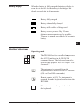
Battery display
When the battery is fully charged the battery display is
seen also to be full. As the battery is discharged, the
display records this in 4 increments.
CO
Battery fully charged
IN
Battery almost fully charged
ID
Battery still capable of being used
PM
Battery reserve power. Only 25 more
FS
distance measurements may be possible.
The user is warned accordingly of an empty
SC
battery.
OC
BK
IO
Graphical status icons
Operating mode
AR
The TPS1000 can be controlled only across
the RS232 interface in the GEOCOM
RC
command format. The keyboard cannot be
used for this purpose. Refer to chapter "On- EG
line mode".
CA
The instrument is operated from the
keyboard and/or across the RS232 interface
CT
(GSI- or GeoCOM commands).
Remote control is ON. The instrument is
BC
operated from the keyboard and/or from the
RCS1000.
DF
The instrument can be operated only from
the keyboard.
SD
TS
IX
© Leica
TPS-System 1000-2.4.0en
53
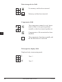
Data storage device field
No memory card has been inserted.
MC
CO
IN
Memory card has been inserted.
ID
PM
Compensator field
SC
The compensator cannot be read. Instrument is either at too great a gradient,
unstable, or has been turned quickly, etc.
OC
BK
Compensator or Hz-correction has been
disabled.
FS
IO
The compensator functions normally and
the Hz directions are corrected.
AR
RC
EG
Telescope face display field
CA
Displayed only in measuring mode.
CT
I
Face 1
BC
II
Face 2
DF
SD
TS
IX
54
TPS-System 1000-2.4.0en
© Leica
Automatic target recognition
Automatic target recognition is activated.
CO
Automatic target tracking (LOCK) is
activated, but no prism has been targeted or IN
lock to prism has been lost.
ID
LOCK is activated, target is tracked.
PM
Lock to prism has been lost. Search is in
progress.
FS
ATR or LOCK is not active.
SC
OC
BK
Key-mode field
IO
has been pressed.
AR
At least one function key in the second level
has been assigned (in addition to "HELP"). RC
Further digits need to be keyed in.
Displayed when a menu list has more than
10 entries.
EG
CA
Insert-mode in entry fields activated.
CT
BC
DF
Instrument busy
Instrument busy.
This icon is displayed in the middle of the
main display area.
SD
TS
IX
© Leica
TPS-System 1000-2.4.0en
55
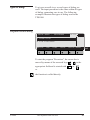
Function keys
CO
IN
F2
F3
F4
F5
F6
Shift
1000Z03
F1
ID
The assignment of the orange keys varies with
circumstances. This assignment permits access to
functions which are dependent on the particular dialog.
To assist user familiarity, the command logic is
organized so that the same command normally appears
at the same function key.
Detailed information regarding the functions assigned
to these keys can be found in the chapter "Instrument
operation".
PM
FS
SC
OC
BK
IO
There are two levels for the function keys:
AR
...
RC
1st level
...
2nd level
EG
CA
Special function key assignments
CT
This is the "HELP" key for every dialog.
Here the functionality of the current dialog is briefly
described.
BC
DF
Aborts a function or application and returns to the main
menu. All entries in the last dialog of the function or
application are rejected.
SD
TS
IX
56
TPS-System 1000-2.4.0en
© Leica
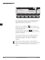
Fixed keys
CO
CODE
aF...
CONT
ON
OFF
1000Z03
IN
ESC
ID
PM
Fixed keys (white)
The functions associated with these keys are available
at all times. These keys bypass the current operation
sequence to access a system function, returning to
exactly the same display afterwards.
FS
SC
OC
BK
Calls code input. See chapter "Code information".
IO
Switches illumination ON/OFF. See chapter "Instrument operation".
AR
RC
Levels-up the instrument. See chapter "Instrument
operation".
aF...
Various functions. See chapter "Instrument operation".
EG
CA
Turns the instrument ON/OFF.
Confirms the values in the dialog, continues to the next
display.
CT
BC
Returns one step back to the previous dialog. No
entered values or parameters are retained.
DF
SD
TS
IX
© Leica
TPS-System 1000-2.4.0en
57
Control keys
CO
IN
1000Z03
ID
PM
FS
Sets the focus and scrolls through the dialog.
SC
Positions the cursor in order to edit numbers and letters,
to insert or delete, and for positioning within a row.
OC
BK
IO
AR
Enter keys
RC
EG
7
8
9
4
5
6
1
2
3
0
• +/-
1000Z03
CE
CA
CT
BC
...
DF
Input in numerical fields, or selecting and starting of
functions with a related number.
Decimal point and sign.
SD
Confirms the input within a line or the choice from a
list.
TS
Deletes the last digit or letter entered.
IX
58
TPS-System 1000-2.4.0en
© Leica
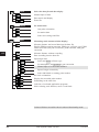
Menu tree (Main menu
after ON)
CO
EXTRA
Help functions
IN
On-line mode (GeoCOM)
Format the memory card
ID
Remote Control Mode (only TCA-Versions)
CAL
PM
Display and determination of instrument errors
Determine the compensator index errors (l,t)
FS
Determine the vertical index error (i)
Common determination of errors for the line of sight (HZcollimation) and optionally (only 1700/1800-instruments) for the SC
tilting axes (c, a)
Common determination of errors for the vertical index and line
of sight, and optionally (only 1700/1800-instruments) for the
tilting axes (i, c, a)
OC
BK
Optional determination of the ATR collimation or common
determination of the ATR collimation and the errors for line-ofsight and index (only TCA versions)
IO
AR
CONF
User configuration, system configuration
RC
Set date and time
Define range of functions
EG
Set GSI interface parameters
Set GeoCOM interface parameters
Enter an individual instrument name
CA
Set auto-start application
System protection, define / modify the system password
8
CT
User settings
Definition of the recording template
BC
Definition of the display in measuring mode
Define or edit user template
DF
Select a user template
Select EDM-type (only T versions)
SD
Display software information
TS
IX
© Leica
TPS-System 1000-2.4.0en
59
DATA
Select the data file and data display
Manual input of data
CO
Data search and display
Erase file
IN
SETUP
ID
Set station data
One-point orientation
Set station data
PM
Select user settings and files
MEAS
FS
Measuring mode (measured data display)
SC
Measure distance and record data into the data file
Display EDM measuring program, EDM type, reflector type, EDM
offset correction (only for T versions), prism constant, total ppm
correction
OC
BK
Measure distance without recording
Data recording into the data file
Input target data
IO
Select and define reflector type
Set atmospheric and geometric ppm correction
AR
Manual input of a horizontal distance
Input of target eccentricity
RC
Select individual or running point number
Hz-circle orientation
EG
Display last recorded point number
Positioning in the other face
CA
Calls list of on-board application programs
Select existing code function, enter a code block
CT
BC
DF
Coloured field not accessible when in reduced functionality mode
SD
TS
IX
60
TPS-System 1000-2.4.0en
© Leica
Instrument operation
Main menu
After the instrument has been switched on, the
instrument model and software version are briefly
displayed. The instrument carries out a system test and
then engages the main menu.
The special significance of the main menu is that all
fixed system functions and all loadable applications can
be started from it, with the exception of the CODE
function, which can be called from any dialog which
permits data to be stored.
The following overview indicates the assignment of the
various functions to the function keys of the main menu
and to the fixed keys.
CO
IN
ID
PM
FS
SC
OC
IO
AR
RC
EG
CA
CT
BC
DF
SD
TS
IX
© Leica
TPS-System 1000-2.4.0en
61
Fixed-key occupation in
the main menu
CO
14:03
MAIN MENU : PROGRAMS
Orientation
Resection
Stakeout
Tie Distance
IN
1
2
3
4
ID
EXTRA
CAL
CONF
DATA
SETUP MEAS
HELP
PM
F1
F2
F3
F4
F5
F6
FS
External control by GeoCOM commands; remote
control with RCS1000; formatting memory card. See
chapter "Extra".
SC
OC
Determines axial error and inspects electronic bubble.
See chapter "Checking and adjusting".
IO
Settings for accommodating to user requirements, e.g.
units, interface parameters. See chapter
"Configuration".
AR
RC
Data- and file management. See chapter "Data
management".
EG
Input of station data and orientation, selection of user
template and measurement file. See chapter "Set station
data".
CA
CT
Measurement and recording. See chapter "Measurement
and recording".
BC
DF
SD
TS
IX
62
TPS-System 1000-2.4.0en
© Leica
Fixed-key occupation
A code block with additional information is defined and
CO
recorded. In general, the key is activated when
measurements or coordinates can be recorded for a
IN
point. For details, see chapter "Code information".
Various illuminators can be switched on, and the
brightness adjusted.
Depending on the outfit, they are:
- Display contrast
- Display illumination
- Crosshair illumination
- EGL1 guide light
- Laser eyepiece
- Laser pointer for DIOR and DISTO
- Laser plummet
ID
PM
FS
SC
OC
For details, see chapter "Illumination".
aF...
IO
Various often-used basic functions which must be
adjusted quickly:
• Select user setting, file
• EDM settings
• Compensator settings
• EDM test
• Beep settings
• V-angle settings
• Automatic switchoff criteria
• Settings for automatic target recognition ATR1
• Accessories for telescope
AR
RC
EG
CA
CT
For details, see chapter "aF... -Additional functions".
BC
The instrument is switched on, switched off, or switched DF
to Sleep mode. For details, see chapter "ON/OFF".
SD
TS
IX
© Leica
TPS-System 1000-2.4.0en
63
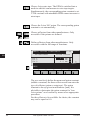
Measurement &
recording
The measurement dialog is of fundamental importance
in the TPS-System 1000. Using the appropriate function
keys, all of the information relevant to a measurement
can be entered. The comprehensive functionality also
covers requirements dictated by unusual circumstances.
The comprehensive flexibility of the measurement
dialog is also available for all loadable applications but
occasionally requires slight modification.
CO
IN
ID
PM
The following basic functions are available:
- Simultaneous measurement of distance and angle,
using "ALL" for recording
- Separate distance measurement using "DIST" and
- Storage of the measurement "REC".
FS
SC
OC
The horizontal circle can be oriented (Hz0) and
application programs started.
IO
Input of various target point data under "TARGT".
Therse are:
- Entering target point numbers
- Target-point eccentricity
- Input of remarks 1 - 9
- Choosing various prisms and retro tape targets
- Defining various prism constants
- Entering values used to calculate the atmospheric
and geometrical distance corrections
- Entering the refraction coefficient
- Recalling the last point number to be recorded
- Changing the telescope face
- Entering manually-determined horizontal distances
- Incrementing the point number
- Switching from current- to other point numbers.
AR
RC
EG
CA
CT
BC
DF
SD
TS
IX
64
TPS-System 1000-2.4.0en
© Leica
MEAS\ MEASURE MODE (GSI) 14:03
Point no. :
Remark 1
:
Refl.Height :
Hz
:
V
:
Horiz.Dist. :
ALL
1
----0.000 m
295°22'40"
91°20'30"
----- m
DIST
REC
TARGT
Height diff :
Easting
:
Northing
:
Elevation :
HELP
F1
-----------------
LAST
F2
Hz0
I<>II
F3
F4
CO
αNUM
IN
m
m
m
m
ID
PROG
F5
PM
F6
FS
The data shown above represent the standard display
template.
SC
OC
Distance measurement and measurement-block
recording. The recorded measurement block
corresponds to the active recording template.
IO
Measure a distance and display it.
AR
Measurement block recording. The recorded
measurement-block corresponds to the active recording
template. The last measured distance is also recorded.
Call-up target point data (refer to chapter "Target point
data")
Sets the horizontal circle to 0° 00' 00" (0.0000 gon ) or
enter value (meaningful only at face I).
Sets the current point number to be the same as the last
one recorded.
RC
EG
CA
CT
BC
DF
SD
TS
IX
© Leica
TPS-System 1000-2.4.0en
65
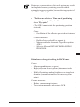
Change telescope face. ΔHz and ΔV are displayed. The
instrument should be turned until the differential values
are both "0.000", and then the same target point appears
in the telescope. This procedure is useful in conditions
of poor visibility.
Motorized theodolites turn automatically to the
other telescope face (TM/TCM- and TCA versions).
CO
IN
Calls the application programs dialog. From here, the
application programs can be started.
ID
PM
FS
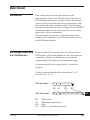
Explanation of the elements of measurement
SC
OC
Hz
=0
IO
AR
Slo
pe
ta
dis
nce
RC
V
EG
Reflector
height
Hz
1000QS35
CA
CT
BC
Height
difference
Instrument
height
H
nta
orizo
l dist
ance
DF
SD
Hz = Horizontal angle
V = Vertical angle
TS
IX
66
TPS-System 1000-2.4.0en
© Leica
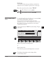
Measuring distances and
angles together
CO
Simultaneous measurement and recording.
IN
MEAS\ MEASURE MODE (GSI) 14:03
Point no. :
100
Remark 1
:
new
Refl.Height :
1.500 m
Hz
:
214°52'45"
V
:
85°25'17"
Horiz.Dist. :
100.251 m
ALL
DIST
REC TARGT Hz0 αNUM
Height diff :
23.650 m
Easting
:
76.943 m
Northing
:
1902.437 m
Elevation :
523.650 m
HELP
F1
LAST
F2
F3
I<>II
F4
ID
PM
FS
SC
OC
PROG
F5
IO
F6
AR
Hz-angle measurement is carried out after the distance
has been measured. Immediately afterwards all data is
stored.
RC
EG
Therefore the instrument may only be moved after data
storage is complete.
CA
CT
The data is automatically recorded after the distance has
been measured. The distance, and all data which depend
BC
on it, are then displayed with the tag "-----", which
indicates that the data storage is complete.
DF
SD
TS
IX
© Leica
TPS-System 1000-2.4.0en
67
Measuring distances and
angles separately
CO
Perform a distance measurement.
Record the resulting data.
IN
ID
MEAS\ MEASURE MODE (GSI) 14:03
Point no. :
100
Remark 1
:
----Refl.Height :
1.500 m
Hz
:
214°52'45"
V
:
85°25'17"
Horiz.Dist. :
100.251 m
ALL
DIST
REC TARGT Hz0 αNUM
Height diff :
23.650 m
Easting
:
76.943 m
Northing
:
1902.437 m
Elevation :
523.650 m
PM
FS
SC
OC
HELP
LAST
IO
F1
F2
F3
I<>II
F4
PROG
F5
F6
AR
This procedure offers the option of realigning the
telescope on another point after measuring the distance
and before measuring the angle. In this way two points
can be used for measurements of angle and distance.
RC
EG
It is therefore possible to record inaccessible points,
e.g. house corners, fences surrounded by hedges.
CA
1000QS36
BC
DF
1000QS37
CT
SD
Measuring DISTANCE
TS
Storing DATA
IX
68
TPS-System 1000-2.4.0en
© Leica
For calculations which depend on distance, the V-angle
after completion of the distance measurement is used,
along with the current Hz-direction. Consequently,
calculated heights and height differences are retained
and the coordinates for easting and northing which
correspond to the new Hz direction are recalculated
using the last-measured distance.
CO
IN
ID
The V-angle displayed corresponds to the position of
the telescope on completion of the distance
measurement. The V-angle is not altered until the
measurement is recorded, the last recorded point
number is recalled, a new distance is measured,
or
is pressed.
PM
FS
SC
When distances, heights, or height differences are
displayed as empty fields (i.e. -----), the V-angle is
continuously displayed and updated.
OC
IO
If, after the distance has been measured, changes are
made to the target-point data which have an influence
on the distance measured or on the height and height
difference (e.g. ppm, prism constant, reflector height,
refraction coefficient), the dependent data will be
correspondingly verified.
AR
RC
EG
CA
CT
BC
DF
SD
TS
IX
© Leica
TPS-System 1000-2.4.0en
69
Target-point data
Activates the "TARGET" function from the
Measurement mode (GSI) dialog.
The following target-point data can be entered here:
- The target point number
- Incremental target point number interval
- Remarks 1 - 9
CO
IN
ID
The function keys are used for:
- Choosing various prisms and retro tape targets
- Defining prism constants
- Entering values used to calculate the atmospheric
and geometrical distance corrections
- Entering the refraction coefficient
- Entering manually-measured horizontal distances
- Entering the target-point eccentricity
- Switching from current- to other point numbers.
PM
FS
SC
OC
IO
14:03
MEAS\ TARGET DATA
Increment :
102001
Runn. PtNo :
12A20001
Refl.Height :
1.500 m
Remark 1
:
----Remark 2
:
----Remark 3
:
----PRISM PPM D INP OFFS INDIV αNUM
Remark 4
:
----Remark 5
:
----Remark 6
:
----Remark 7
:
----Remark 8
:
----Remark 9
:
-----
AR
RC
EG
CA
CT
HELP
BC
F1
F2
F3
F4
F5
F6
DF
SD
TS
IX
70
TPS-System 1000-2.4.0en
© Leica
Choose the prism from 6 possibilities : Leica circular
prism, retro tape target (not in the T/TM versions),
Leica 360° prism, 3 user-defined prisms.
Setting the atmospheric ppm and the geometric ppm
(height and projection) and the refraction coefficient.
CO
IN
Enter a manually-measured horizontal distance.
Enter the data for an eccentric target point.
ID
Change between individual and running point number.
PM
FS
SC
Remarks
OC
Supplementary information entered (remarks, type of
point, topological data etc.) can be stored under
"Remarks" .
IO
The remarks must be defined in the recording template.
They are stored along with every measurement. The
value is retained until it is changed.
If the remarks are defined in the display template, they
can be entered directly in the measurement dialog.
Additional information can also be stored in code
blocks instead of under "Remarks". For detailed
information about the use of additional information,
refer to the chapters "Code information" and "Data
format".
AR
RC
EG
CA
CT
BC
DF
SD
TS
IX
© Leica
TPS-System 1000-2.4.0en
71
Incrementing point
numbers
The numerical and alphanumerical parts of a point
number can be incremented individually. The increment
is defined as a numerical mask.
CO
MEAS\ TARGET DATA
Increment :
Runn. PtNo :
Refl.Height :
Remark 1
:
Remark 2
:
Remark 3
:
IN
ID
PRISM
PM
F1
PPM
14:03
102001
12A20001
1.500 m
-------------
D INP OFFS
F2
F3
INDIV αNUM
F4
F5
F6
FS
In the above example, after recording, the next point
number is incremeted to 12B22002 and then to
12C24003 etc. as shown in the display above.
SC
OC
Letters from A to z ( ASCII 065 - 122 ) can be
incremented. This prevents two-way transfer (between
letters and digits) within the alphanumeric range.
Examples:
IO
AR
PtNo
12z001
12A999
12Az100
RC
Increment
1000
000001
1001000
EG
Explanation No transfer of letters
to numbers
No transfer of
numbers to letters
No transfer of letters
CA
MEAS\ MEASURE MODE (GSI) 14:03
WARNING: 152
Overflow of running point no.
after incrementation.
CT
BC
Check point no.
DF
OK
F1
SD
TS
F2
F3
F4
F5
F6
Confirms the warning and the change in the point
number or in the increment.
IX
72
TPS-System 1000-2.4.0en
© Leica
Set and define prisms
Activates the "PRISM" function from the "Target point CO
data" dialog.
IN
MEAS\
PRISM SELECTION
14:03
ID
Select prism
Leica circ. prism:
0.0 mm
Offset corr.:
FOLIE 360°
TAPE
HELP
F1
F2
PM
OFF
F3
PR.1
PR.2
DEF
PR.3
F4
EIN
ON
F5
FS
SC
F6
OC
The active prism is set with the corresponding function
key. This action simultaneously sets the relevant prism
constants.
AR
Offset corr.
The offset correction is only possible when using a
T-version with an EDM attached.
ON
IO
RC
EG
The correction is to be engaged when using
prisms which are standing vertically, in order
to correct the measured distance for the offset CA
between the EDM axis and the telescope
axis.
CT
OFF
When using the tilting Leica prism GPH1A
this correction is not necessary and must
therefore be disengaged.
BC
DF
SD
Choose the Leica circular prism (standard setting).
TS
IX
© Leica
TPS-System 1000-2.4.0en
73
Choose Leica retro tape. The EDM is switched into a
mode in which it can measure to retro tape targets.
Simultaneously, the corresponding prism constant is set.
T/TM-versions with attachable EDM cannot measure to
retro tapes.
CO
IN
Choose the Leica 360° prism. The corresponding prism
constant is set automatically.
ID
PM
,
Choose reflectors from other manufacturers. Only
accessible if the prisms are defined.
FS
Define reflectors from other manufacturers. Only
accessible with the full range of functions.
SC
OC
IO
14:03
MEAS\ PRISM CONSTANTS
Define prism constants
Prism name
Value Prism
AR
Pr.1
Pr.2
Pr.3
0.0 mm x
0.0 mm x
0.0 mm x
FOLIE 360°
RC
PR.1
PR.2
HELP
F1
EG
F2
F3
F4
F5
EIN
EDIT
EDIT
F6
CA
The user can freely define the name and prism constant
(additive constant) for three reflectors and can enter the
type of reflector (prism or retro tape). The prism
constant is always given in millimetres [mm]. It is
advisable to determine the prism constant for "non
Leica prisms" on a baseline by means of an appropriate
procedure.
For the reflector to be available for choice, the constant
may not be equal to 0.0.
CT
BC
DF
SD
TS
IX
74
TPS-System 1000-2.4.0en
© Leica
Prism type:
The symbol of the prism type indicates whether the
reflector is to be treated as a prism or as a retro tape.
Move the cursor bar to the column "PRISM"
CO
The reflector is set as a prism.
x
IN
The reflector is set as a retro tape.
ID
PM
Reduced input of ppm
values
For standard applications the distance is corrected only
on account of atmospheric influences.
The geometrical correction and the projection
distortions are set to "0.00". Heights are reduced with
the standard refraction coefficient (see the chapter
"Define functionality").
Activate the function "PPM" from the dialog "Targetpoint data".
FS
SC
OC
IO
AR
14:03
Enter your correction values
MEAS\
PPM CORRECTIONS
Atm. press. :
Temperature :
ppm total
RC
1013.3 mbar
12.0 °C
:
EG
-0.0
FOLIE 360°
PR.1
PR.2
EIN
EDIT
CA
HELP
F1
F2
F3
F4
F5
F6
CT
Input of air pressure and temperature
BC
or
DF
Input of ppm value.
The values for pressure and temperature are erased.
SD
TS
The dialog is dependent on the setting within
"FUNCTIONALITY".
© Leica
TPS-System 1000-2.4.0en
IX
75
Comprehensive distance
corrections (ppm)
A distinction is made between atmospheric (ppm) and
geometric (ppm) corrections, the sum of which is used
as the final distance correction.
CO
• Atmospheric correction
IN
The atmospheric distance corrections are derived from
the dry-air temperature, air pressure or height over mean
sea-level, and relative air humidity or wet-air
temperature.
ID
PM
FS
14:03
12.0
°C
1013.3 mBar
0.0
:
0.0
:
0.0
:
0.0
MEAS\ ATMOSPHERIC CORR.
Temperature :
Atm. press. :
Temp.wet-b. :
ppm atmospheric
ppm geometric
ppm total
SC
OC
GEOM
IO
REFRA P<>E
HELP
F1
AR
F2
F3
%<>T' ATM=0 EDIT
EDIT
F4
F5
F6
RC
Settings for the geometrical correction.
EG
Settings for the refraction correction.
CA
Toggle between air pressure and height above mean sealevel.
CT
Toggle between relative air humidity and wet-air
temperature.
BC
Set the atmospheric ppm to "0.00". (Individual
parameters are set to the standard atmospheric values,
corresponding to the atmospheric correction ATM=0)
DF
SD
The dialog is dependent on the setting within
"FUNCTIONALITY".
TS
IX
76
TPS-System 1000-2.4.0en
© Leica
• Geometrical correction
The geometrical distance correction is derived from the
projection distortion and the height above the reference
datum.
The calculation of the geometrical ppm follows the
formula for the Transversal Mercator Projection.
The individual factors are: the scale factor of the line of
projection (central meridian, Gauss-Krüger = 1.0, UTM
= 0.9996, etc.); the offset from the line of projection;
the height above the reference datum (normally this is
the height above mean sea-level); and an additional
individual scale correction.
CO
IN
ID
PM
FS
The distance without any projection distortion is used to
determine the height difference. The individually-set
SC
scale adjustment is always applied to the distance.
OC
The individual scale correction can be used to enter a
total geometrical correction.
IO
14:03
MEAS\ GEOMETRIC CORR.
Scale C.M. :
1.0000000
Offset C.M. :
51000 m
Height aRef :
350 m
Indiv. ppm :
0.0
ppm geometric:
AR
RC
-22.9
EG
GEO=0 EDIT
0.0
0.0
ppm ref. level
:
ppm map projection :
CA
HELP
F1
CT
F2
F3
F4
F5
F6
BC
Sets the geometrical ppm to "0.00".
The scale on the Central Meridian is set to
"1.0000000". The other parameters are set to "0.00".
DF
SD
TS
IX
© Leica
TPS-System 1000-2.4.0en
77
• Refraction correction
The refraction correction is taken into account during
the calculation of the height difference.
CO
IN
MEAS\ REFRACTION CORR.
Set coeff. of refraction
ID
Correction
:
Refr. coeff. (k) :
Definition of k
:
14:03
ON
0.13
Method 1
PM
DEFLT EDIT
HELP
FS
F1
F3
F2
F4
F6
F5
SC
Sets the refraction coefficient to standard values.
(Method 1: k = 0.13, Method 2: k = 0.07)
OC
IO
Correction
ON/OFF
Turns the refraction coefficient on and off.
AR
RC
Refr. coeff. (k)
EDIT
Enters a new value for k.
EG
Definition of k
LIST
Defines k.
CA
CT
Selecting the method of calculating the refraction
correction. Both methods calculate the same result with
different input values.
BC
DF
Method 1:
SD
TS
Method 2:
1-k
2R
0.5 -
( Standard value k = 0.13 )
k
2
( Standard value k = 0.07 )
R
IX
78
TPS-System 1000-2.4.0en
© Leica
Manual distance entry
Enter the horizontal distance, which was measured with
a tape for instance.
Immediately after confirmation of input, the horizontal
distance is shown corrected for the geometrical ppm.
After the distance has been entered, the V-angle is set to CO
"horizontal" 90° ( 100 gon ) or 270° ( 300 gon ). The
coordinates are calculated using the corrected horizon- IN
tal distance, the Hz-direction, and the V-angle. Heights
are always corrected for earth curvature and are
ID
corrected for refraction according to the parameter
settings.
PM
Activates the dialog which allows the horizontal
distance to be entered manually.
FS
MEAS\ DISTANCE TO TARGET 14:03
SC
Manual distance entry
Horiz.Dist.:
OC
----- m
IO
EDIT
HELP
AR
F1
F2
F3
F4
F5
F6
RC
EG
The reflector height is temporarily set to the value for
the instrument height and so there is always a height
difference of "0.000".
The slope distance is the same as the horizontal
distance.
CA
CT
BC
DF
SD
TS
IX
© Leica
TPS-System 1000-2.4.0en
79
Target eccentricity
CO
If the reflector cannot be set up directly, or if it cannot
be seen from the instrument, the values for eccentricity
can be entered. All of the displayed and stored values
are calculated in relation to the centre.
IN
Each time that data is stored, the values are
automatically reset to "0.000".
ID
PM
Activates the function "OFFS" in the dialog "Targetpoint data".
FS
14:03
MEAS\ OFFSET DATA
Enter offset data
SC
Shft length :
Shft trans :
Shft height :
OC
0.000 m
0.000 m
0.000 m
DEFLT EDIT
IO
HELP
AR
F1
F2
F3
F4
F5
F6
RC
EG
CA
Shft height (-)
CT
1000Z44
BC
DF
Shft trans (+)
SD
Shft length (-)
TS
Centre
IX
80
TPS-System 1000-2.4.0en
© Leica
Individual point number
MEAS\ TARGET DATA
Increment :
Runn. PtNo :
Refl.Height :
Remark 1
:
Remark 2
:
Remark 3
:
PRISM
PPM
14:03
102001
12A20001
1.500 m
-------------
D INP OFFS
CO
INDIV αNUM
IN
HELP
F1
F2
F3
F4
F5
ID
F6
Toggles between running ("RUNN") point number and
individual ("INDIV") point number.
PM
FS
SC
OC
IO
AR
RC
EG
CA
CT
BC
DF
SD
TS
IX
© Leica
TPS-System 1000-2.4.0en
81
Set station data
CO Select user template and
measurement file
Activates the "SETUP" function from the main menu.
Choose the data carrier for storing the data, the user
setting, and the measurement- and data files.
IN
ID
PM
SETUP\ START-UP DISPLAY 14:03
Select user template & files
User templ. :Polar(Standard)
Rec. device :
Memory Card
Meas. file :1 √ FILE01.GSI
Data file :2 √ FILE02.GSI
FS
SC
ORI
STAT
LIST
HELP
OC
F1
IO
F2
F4
F3
F5
F6
AR
RC Station entry/setting
EG
The coordinates of a station point are set.
A known direction to a tie point can be entered.
Activates the function "STN" from the dialog "STARTUP DISPLAY".
CA
CT
SETUP\
BC
Station no. :
Inst.Height :
Stn.Easting :
Stn.Northng :
Stn.Elev. :
HZ
:
DF
14:03
1
1.520 m
100.000 m
2000.000
500.000 m
222°42'33"
STATION DATA
REC
IMPOR αNUM
Hz0
HELP
SD
F1
VIEW
F2
F3
F4
F5
F6
TS
IX
82
TPS-System 1000-2.4.0en
© Leica
After the point number of the station point has been
entered, the coordinates can be input directly using the
numeric keys or can be imported from the data file of
the memory card.
CO
Recording station data
IN
The station data (point number, easting, northing,
station height, reflector height and instrument height)
are recorded in the measurement file of the active data
carrier. The coordinates are set as station coordinates.
ID
PM
The coordinates displayed are set as station coordinates. FS
In both instances there is a jump to the "MAIN MENU"
SC
dialog. "Measure mode" can be activated there with
.
OC
IO
Setting and entering Hz direction (Hz0)
AR
Set Hz direction to 0° 00' 00" (0.0000 gon) or enter a
known value.
RC
EG
Target the tie point exactly.
The direction must always be set using face I.
Enter the new direction to the tie point.
CA
SETUP\ Hz-CIRCLE ORIENT. 14:03
CT
Set Hz-direction
Hz
:
BC
123°17'56"
Hz=0
HOLD
DF
EDIT
HELP
F1
SD
F2
F3
F4
F5
F6
TS
Sets Hz to 0° 00' 00" (0.0000 gon).
IX
© Leica
TPS-System 1000-2.4.0en
83
Instead of entering a value, this can be set by turning the
instrument.
Secures the value (clamp the circle)
CO
Target the tie point exactly.
Releases the circle.
IN
ID
This function is also activated from other dialogs in
order to enter the Hz direction.
PM
Import point data (Import function)
FS
As well as the measuring mode, the function "Import
point data" has a special significance, because it is also
used in many applications. This function enables point
coordinates to be read from the data file and
transferred to the application currently in use.
SC
OC
IO
SETUP\
AR
14:03
1
1.520 m
100.000 m
2000.000
500.000 m
222°42'33"
STATION DATA
Station no. :
Inst.Height :
Stn.Easting :
Stn.Northng :
Stn.Elev. :
HZ
:
RC
EG
REC
IMPOR αNUM
Hz0
HELP
VIEW
CA
F1
F2
F3
F4
F5
F6
CT
Direct data search
After the complete point number has been entered, the
coordinates of the first data set (the search always starts
at the beginning of the file) are accepted for the
application. The data set found is generally not
displayed and the appropriate application activates the
subsequent dialog.1
BC
DF
SD
TS
The dialog "STATION DATA" is an exception to this
rule and the coordinates there are displayed.
1
IX
84
TPS-System 1000-2.4.0en
© Leica
Controlled data search
After the complete point number has been entered, the
coordinates of the first data set found are displayed
(The search always starts at the beginning of the file).
CO
Point found:
IN
SETUP\
SEARCH RESULTS
Point no. :
Stn.Easting :
Stn.Northng :
Stn.Elev. :
Refl.Height :
<<REP REP>>
<--
-->
Inst.Height :
14:03
14/20
1
0.000 m
0.000 m
0.000 m
1.500 m
ID
PM
NEW S
FS
0.000 m
HELP
F1
SC
F2
F3
F4
F5
F6
OC
The first line contains the scroll bar which graphically
displays the position of the data block within the data
file, as well as the data block number in relation to the
total number of data blocks within the file.
Repeat the point number search in the direction of the
beginning of the data file in order to look for points
which have been recorded more than once with the
same point number or with placeholders.
IO
AR
RC
EG
Repeat the point number search in the direction of the
CA
end of the data file in order to look for points which
have been recorded more than once with the same point
number or with placeholders.
CT
Sequential display of the points (upwards within the
file).
BC
Sequential display of the points (downwards within the
file).
DF
Starts a new point search. The function proceeds as
after an unsuccessful point search.
SD
Accepts the displayed value for the appropriate function TS
or application.
IX
© Leica
TPS-System 1000-2.4.0en
85
Point not found:
If no points are found then the error message ERROR
1355 is displayed, which means that no points have
been found with the given point number in the file.
Confirm this with the
key - the user will be
prompted to enter the point number again.
CO
IN
ID
SETUP\
14:03
SEARCH POINT
Rec. device :
Memory card
Search in : 1 √ FILE01.GSI
PM
Point/Code :
FS
1
SEARC αNUM
HELP
SC
F1
OC
F2
F3
F4
F5
F6
The file for the data search can be changed and/or a new
point number can be entered
IO
AR
/
RC
EG
CA
Direct data search
After the complete point number has been entered, the
coordinates of the first data set (the search starts at the
beginning of the file) are accepted by the application.
The data set found is not generally displayed and the
appropriate application activates the subsequent dialog.1
Controlled data search
The coordinates of the point are displayed. To continue,
see "Controlled data search" on page 85.
CT
BC
DF
SD
TS
1 The
dialog "Station data" is an exception to this rule
and the coordinates in it are displayed.
IX
86
TPS-System 1000-2.4.0en
© Leica
Placeholder (wild cards)
The search for stored data can be made easier if a
placeholder is used instead of the complete point
number. In the TPS1000, a decimal point "." is used
instead of the more usual star "*", because it is more
easily entered. There is no entry corresponding to "?".
CO
Example of the use of placeholders:
ID
Input
Results
Remarks
PM
11.
11, 110, 1101, 11ABC5,
111111
After 11 there can be any
character and in any
amount.
FS
.11
11, ABC11, 11111
Before 11 there can be any
character and in any
amount.
1.0
10, 100, 1ABCD0,
11111110
Between 1 and 0 there can
be any character and in
any amount.
.10.
10, 3410ABC, 111110,
1000000
A 10 must be present at
least once.
10, 341ABC0, 1123Z0Y,
1001A000
A 1 must be present in
front of a 0 at least once,
and any amount of
characters can be present
between them.
.1.0.
IN
SC
OC
IO
AR
RC
EG
CA
CT
If a number with placeholder is entered instead of the
BC
complete point number, the controlled data search is
always started and the first matching data set is
displayed. The subsequent procedure is the same as that DF
used when entering a complete point number.
SD
TS
IX
© Leica
TPS-System 1000-2.4.0en
87
1-point orientation
CO
All of the entries relevant to a new instrument
configuration are summarized in this function and can
be dealt with very quickly.
Activate the function in the dialog "START-UP
DISPLAY" (page 82).
IN
SETUP\ 1-PT. ORIENTATION 14:03
ID
Station
:
Backsight :
Inst.Height:
Refl.Height:
Δ Hz-Dist. :
PM
FS
ALL
DIST
1
A
1.500 m
1.000 m
----- m
HELP
SC
F1
INPUT αNUM
REC
I<>II VIEW
F2
F3
F4
F5
F6
OC
IO
Enter the numbers of the station point and of the
backsight point respectively. The appropriate point is
immediately searched for in the data file and, if the
search is successful, the coordinates will be assigned to
the station point and backsight point without this fact
being displayed.
AR
RC
EG
After the instrument height and the reflector height have
been entered, target the backsight point and measure the
distance and/or the direction.
CA
Measure the distance and determine the direction, and
store the measurement block. The graduated circle is
orientated. The difference between the calculated
distance and the measured distance to the backsight
point is displayed.
CT
BC
DF
Measure the distance. The difference between the
calculated distance and the measured distance to the
backsight point is displayed.
SD
TS
IX
88
TPS-System 1000-2.4.0en
© Leica
Determine the direction and store it, including the
previously-measured distance where appropriate. The
graduated circle is orientated.
Determine the direction, but do not store the values.
The graduated circle is orientated.
CO
Using the keyboard, enter the coordinates for the station
or for the tie point. See chapter "Data management".
Activate controlled data search within data file. See
chapter "Data management".
IN
ID
PM
FS
SC
SETUP\ 1-PT. ORIENTATION 14:03
Station
:
1
Backsight :
A
Inst.Height:
1.500 m
Refl.Height:
1.000 m
Δ Hz-Dist. :
----- m
Set station with REC or CONT
OC
IO
REC
AR
HELP
F1
F2
F3
F4
F5
RC
F6
EG
Station data are set and are stored in the measurement
file.
CA
Station data are set.
CT
In both of these cases, there is a jump to the main menu, BC
from where the measuring mode can be called by using
.
DF
SD
TS
IX
© Leica
TPS-System 1000-2.4.0en
89
Data management
Activates the "DATA" function from the "MAIN
MENU".
CO
Using data management, the user has the possibility to
display data from within a chosen data file, or to delete
data blocks or data files.
Point numbers, codes and remarks can be edited.
Individual points, and points saved several times with
the same point number, can be searched for, displayed,
and deleted.
When calling up the function, the last point number will
automatically be displayed in the file at "Point/Code"
file.
IN
ID
PM
FS
SC
DATA\FILE & PT SELECTION 14:03
Rec. device :
Memory card
Memory size :
511.5KB
Free
:
504.0KB
Point/Code :
4
File
:2 √
FILE01.GSI
File size :
1.2KB
INPUT
SEARC αNUM
OC
IO
AR
HELP
DEL
RC
F1
F2
F3
F4
F5
F6
EG
CA
CT
BC
DF
SD
TS
IX
90
TPS-System 1000-2.4.0en
© Leica
Entering coordinates
Enters point coordinates in the data file.
DATA\
14:03
IN
FILE02.GSI
5
----- m
----- m
----- m
ID
MANUAL ENTRY
Enter coordinates
Data file :2 √
Indiv.PtNo :
Easting
:
Northing
:
Elevation :
CO
PM
EDIT
HELP
FS
F1
F2
F3
F4
F5
F6
SC
The height is only stored if a value has been entered.
OC
IO
AR
Deleting data
RC
Deletes the current data file.
EG
DATA\FILE & PT SELECTION 14:03
WARNING: 1352
File FILE01.GSI will
definitely be deleted!
CA
CT
Do you really want to delete?
NO
F1
F2
YES
F3
F4
BC
F5
F6
DF
SD
The file will not be deleted.
TS
Confirms deletion of the data file.
IX
© Leica
TPS-System 1000-2.4.0en
91
View data
/
CO
IN
Activates the function from the dialog "DATA FILE/
SELECT POINT".
DATA\
14:03
14/20
17
286°12'36"
275°45'12"
123.236 m
+0051+000
DATA VIEWING
Point no. :
HZ
:
V
:
Slope dist. :
ppm/mm
:
ID
PM
FS
<<REP REP>>
<--
HELP
|<<- ->>|
F1
SC
F2
F3
-->
F4
NEW S
DEL
F5
F6
The data is shown point by point, in accordance with the
template used at the time of the recording. The data
displayed can therefore vary, depending on the point
currently being considered.
OC
IO
AR
The subsequent procedure, and the options for entering
point numbers, are the same as with the function
"Import data", with the exception of the following
functions:
RC
EG
Jumps to the beginning of the data file. This key is not
assigned if the point displayed is the first in the data
file.
CA
CT
Jumps to the end of the data file. This key is not
assigned if the point displayed is the last in the data file.
BC
DF
SD Edit data
TS
If the editing of data is permitted by the range of
functions, then point numbers, code information,
remarks etc. can be altered. True measurement data,
such as directions and distances, cannot be altered.
IX
92
TPS-System 1000-2.4.0en
© Leica
Leica prisms and retro
tapes
Prism for attachable
EDM
When using the theodolite in connection with DI1001,
DI1600, or DI2002 EDMs for measuring over short
distances, we recommend using the GPH1A singleprism holder.
CO
IN
ID
PM
1000Z024
FS
SC
OC
GPH1A single-prism holder
IO
The height difference between the telescope's optical
AR
axis and the infra-red beam is corrected by the
corresponding difference at the target, therefore aim the
RC
crosshairs at the yellow target mark.
EG
The GPH1Z / GRZ3 single-prism holder is
recommended for measurements with the DI3000.
CA
CT
1000Z56
BC
DF
SD
TS
GPH1Z/GRZ3 single-prism holder
© Leica
TPS-System 1000-2.4.0en
IX
93
Prism for incorporated
EDM
CO
IN
ID
For measuring distances we recommend using the
GPH1 single-prism holder. The intersection of the
vertices of the prism lies exactly at the intersection of
the rotation axes of the reflector and can therefore be
used directly as the target. For perfect targeting of the
GPH1 over longer distances the additional GZT4 target
is recommended. The EDM telescope is adjusted during
manufacture so that the measuring beam lies exactly on
the optical axis.
PM
FS
TC600Z11
SC
OC
IO
AR
GPH1 single-prism holder with GZT4 target plate
RC
EG
Aim the crosshairs at the centre of the reflector.
TCA models are able to aim automatically at the centre
of the prism.
CA
CT
BC
DF
SD
TS
IX
94
TPS-System 1000-2.4.0en
© Leica
The GRZ4 360° reflector
The GRZ4 reflector is a special 360-degree prism and is
available as an option. It allows measurements and
automatic target recognition from any direction.
Since it does not always need to be turned towards the
instrument, the reflector provides additional comfort for CO
a rodman and improved surveying efficiency.
IN
ID
PM
FS
1000Z025
SC
OC
The grouping of the 6 prisms of the 360° reflector
makes
• the accuracy of horizontal measurement and
• the accuracy of vertical measurement
with automatic target recognition independent of the
position of the reflector.
The overall positioning accuracy of the reflector is ±5
mm in distance and ±5 mm for the angle (horizontal and
vertical).When the arrow on the upper rubberized
mount points towards the instrument and therefore the
front face of a prism points towards the EDM, the
accuracy is improved.
The GRZ4 reflector is highly recommended for
topographic and stake-out surveys. Leica circular
prisms are recommended for surveys requiring higher
accuracy than that provided by the GRZ4 prism.
IO
AR
RC
EG
CA
CT
BC
DF
SD
TS
IX
© Leica
TPS-System 1000-2.4.0en
95
Leica retro tapes
CO
IN
Retro tapes can be attached permanently to an object
for the purposes of monitoring or for frequent repeat
measurements. A retro tape may also be useful for the
once-and-for-all marking of a point which is difficult to
access.
The retro tapes should always be attached in the
preferential direction (Leica logo readable acc. to fig.).
ID
1000Z41
PM
1000Z42
FS
SC
OC
1000Z43
Available retro tapes,
attached in the preferential direction.
IO
Special features
AR
• Range up to 180m (600ft)
• No loss of accuracy when retro tape is perpendicular
to the line of sight
• Measurement precision ±3mm when retro tape is at
45°. This precision can be increased by measuring in
two positions.
• For short ranges of up to 10m (33ft) the additional
lens 632 364 is required. (Measuring error without
additional lens > 10mm). It is important that the
additional lens is placed to the instrument in the
correct position (see fig.).
RC
EG
CA
CT
BC
1000Z57
DF
SD
GDV3
Correct position of
additional lens
TS
IX
96
TPS-System 1000-2.4.0en
© Leica
Technical data for measurements to retro foils
Target-mark size
[mm]
Range
[metres]
Accuracy *
(standard deviation)
20 x 20
2 to 40
3 mm
40 x 40
20 to 100
3 mm
60 x 60
60 to 180
3 mm
CO
IN
* The accuracies quoted are valid when the retro tape is
targeted at an angle of up to 45°.
ID
PM
FS
Summary
Prism
Prism constant
Leica circular prism
Leica retro tape
GRZ4 360° reflector
0 mm
+34.4 mm
+23.1 mm
SC
OC
IO
AR
The prism constant is set automatically when the correct
type of reflector is used.
RC
If another make or type of prism is used it is advisable
to determine the constant on a calibration range.
EG
Take care when pointing through windows or if
reflective surfaces are present in the field of view.
Incorrect readings may result.
CA
CT
Other reflectors for precision measurement and for
special applications are also available. Please contact
your Leica agency.
BC
DF
Long distances
© Leica
SD
Over longer distances or in inclement meteorological
conditions it is better to use the GPH3 three-prism
holder or the GPH11 eleven-prism holder, with the
corresponding number of reflectors, irrespective of
whether the EDM is attachable or already built in.
TPS-System 1000-2.4.0en
TS
IX
97
Extra
Activates the "EXTRA" function in the main menu.
CO
The following display refers only to TCA versions. All
other versions lack the "Remote control mode".
IN
ID
14:03
EXTRA\ EXTRA FUNCTIONS
1 On-line mode (GeoCOM)
2 Format memory card
3 Remote control mode ON/OFF
PM
FS
SC
HELP
OC
F1
F2
F3
F4
F5
F6
IO
AR
RC
EG
CA
CT
BC
DF
SD
TS
IX
98
TPS-System 1000-2.4.0en
© Leica
On-line mode
With on-line operation (GeoCOM), the instrument is
switched to a mode which permits communication with,
or control by, a data recorder or PC. This mode operates
across the RS232 interface; the GeoCOM command set
CO
is used.
EXTRA\ EXTRA FUNCTIONS
IN
14:03
NOTICE: 59
Switches to on-line mode.
ID
Do you want to switch?
PM
NO
F1
F2
YES
F3
F4
F5
FS
F6
SC
Returns to the "MAIN MENU" dialog.
OC
Activates the "On-line mode". The operation of the
IO
instrument is now totally controlled across the interface.
For information about data structures, and for the
AR
detailed structure of the control commands, please refer
to the "GeoCOM Reference Manual"(G-560-0en),
RC
which is available only in English. The on-line mode
can be quitted only by pressing
.
EG
CA
CT
BC
DF
SD
TS
IX
© Leica
TPS-System 1000-2.4.0en
99
Format a memory card
CO
This function can be password-protected. To call the
function, first enter the password.
EXTRA\FORMAT MEMORY CARD 14:03
IN
MC
WARNING: 1151
Formatting deletes all data on
the memory card.
ID
ABORT
PM
F1
OK
F2
F3
F4
F5
F6
FS
When the memory card is re-formatted, all data on it are
irretrievably lost.
SC
OC
Ends the function of formatting a memory card and
returns to the "MAIN MENU".
IO
Confirms that the formatting is to go ahead. The storage
capacity of the memory card is ascertained and the card
is formatted accordingly.
AR
RC
EXTRA\FORMAT MEMORY CARD 14:03
Formatting finished.
EG
CA
Memory space of memory card
Total
:
523776 Byte
Free
:
509952 Byte
CT
HELP
F1
BC
DF
F2
F3
F4
F5
F6
Once the card has been formatted, the total memory on
the card and the amount available to the user are shown
on the display. The difference in these amounts relates
to the memory used to manage the files and directories.
SD
TS
IX
100
TPS-System 1000-2.4.0en
© Leica
Remote-control mode
This option switches the instrument into a mode (TCA
models only) to control the operation via a radio
modem or cable from a control unit. All functions,
programs and information are transmitted from the
CO
instrument to the RCS or from the controller to the
instrument. With the help of the remote-control mode it IN
is possible to survey solo. See chapter "RemoteControlled Surveying".
ID
EXTRA\ EXTRA FUNCTIONS
PM
14:03
NOTICE: 62
Switches to Remote Control
mode.
FS
Do you want to switch?
NO
F1
F2
SC
YES
F3
F4
F5
F6
OC
IO
Returns to the "MAIN MENU" dialog.
AR
Activates the remote control mode.
RC
EG
CA
CT
BC
DF
SD
TS
IX
© Leica
TPS-System 1000-2.4.0en
101
Configuration
CO
The configuration of the TPS 1000 enables the
instrument to be matched to user requirements.
Many of the settings need to be adjusted just once,
before the instrument is first used. Others can be
changed when the instrument is used for a completelydifferent purpose.
IN
The instrument is delivered with a configuration which
has a reduced range of functions. This simplifies its use
for standard surveying applications.
ID
PM
14:03
SYSTEM CONFIG.
System date and time
Define functionality
GSI-Communications param.
GeoCOM-Communications param.
Instrument identification
Autoexec-Application
CONF\
1
2
3
4
5
6
FS
SC
INFO
OC
7 System protection
8 User templates
9 EDM-selection
IO
HELP
AR
F1
F2
F3
F4
F5
F6
RC
The following parameters can be set:
- date and time
- defining the functionality
- the GSI communication parameters
- the GeoCOM communication parameters
- the instrument name
- the auto-start application
- the password and parameter for the system
protection
- the user templates
- the type of add-on EDM (for T- and TM-models)
EG
CA
CT
BC
DF
SD
TS
IX
102
TPS-System 1000-2.4.0en
© Leica
In the submenu "User configuration" are set:
- user password
- display screen
- recording screen
- the number of characters for storage
- the names of the user templates
- system language
- units for distance measurements
- the decimal places for display and storage
- units for angle measurements
- units for temperature entries
- units for pressure entries
- display of coordinates
- direction of the horizontal angle measurements
- definition of the telescope face.
CO
IN
ID
PM
FS
SC
The above dialog is dependent on the definition of the
functionality.
The following options are available in the reduced
menu structure:
• Functions where the cursor bar is positioned
• Functions in heavy type (this does not apply to the
instrument itself).
All of the displays which are unaffected by the
functionality are displayed without heavy type.
OC
IO
AR
RC
EG
CA
Shows the version number of the system software.
CT
14:03
CONF\ SOFTWARE INFO
TPS1000 System-Software
GSI 2.20a
(c)Leica AG 1994-1997
All rights reserved
BC
DF
SD
GeoCOM Version 2.20.00
EDM Version 2.20.00 / 41
ATR Version 2.20.00
TS
IX
© Leica
TPS-System 1000-2.4.0en
103
System date and time
Activates the function from the "SYSTEM CONFIG."
dialog.
CO
IN
CONF\
14:03
SYSTEM CONFIG.
Set date and time
ID
Date
Time
PM
:
:
14.01.96 DMY
16:32:47 24h
EDIT
FS
HELP
F1
SC
OC
F2
F3
F4
F5
F6
The editing follows the general rules described in the
chapter "Operating concept". Additionally, the point in
the date and the colon in the time can be skipped during
editing, by using the
key.
IO
AR
RC
EG
CA
Date
DMY (day, month, year)
MDY (month, day, year)
Time
12h (12-hour display)
24h (24-hour display)
The 12-hour time display indicates with an "a" the time
before 12 o'clock and with a "p" the time after.
CT
BC
DF
SD
TS
IX
104
TPS-System 1000-2.4.0en
© Leica
Define functionality
Activates the function from the "SYSTEM CONFIG." CO
dialog.
IN
The range of functions available in the TPS1000 can be
defined. The instrument is delivered with a
ID
configuration which has a reduced range of functions.
PM
CONF\
14:03
FUNCTIONALITY
Select functionality
FS
Show all menus and keys
Show full ppm definition
Enable user configurat.
Allow data editing
:
:
:
:
NO
NO
NO
NO
DEFLT
HELP
F1
SC
YES
OC
FULL
F2
F3
F4
F5
F6
IO
AR
Show all menus and keys
RC
YES
All functions can be activated.
NO
The range of functions which can be
called is reduced.
Functions which are always available are
indicated in heavy type in the dialogs.
EG
CT
BC
Show full ppm definition
YES
CA
Meteorological and geometrical corrections DF
can be entered and a scale factor can be taken
into account. For height calculations, a
SD
refraction coefficient which differs from the
standard value can be entered.
TS
IX
© Leica
TPS-System 1000-2.4.0en
105
NO
CO
Only pressure and temperature, or a ppmcorrection of the distance measurement,
can be entered. Geometrical corrections
and a scale factor are not taken into
account. Heights are calculated using the
standard value for refraction.
IN
Enable user configuration
ID
YES
The user setting can be changed.
PM
NO
The user setting cannot be changed, but a
user setting can always be selected.
FS
SC
Allow data editing
OC
YES
Stored data such as point numbers or
code blocks can be altered.
Measurement data such as angles,
distances or coordinates cannot be
altered. The alteration is carried out
within the function "Editing data".
NO
Stored data cannot be altered.
IO
AR
RC
EG
CA
Sets all settings to NO.
CT
Sets all settings to YES.
BC
DF
SD
TS
IX
106
TPS-System 1000-2.4.0en
© Leica
Interface parameters
(GSI)
Activates the function from the "SYSTEM CONFIG." CO
dialog.
IN
14:03
Set communication parameters
Baud rate
:
2400
Protocol
:
GSI
Parity
:
EVEN
Terminator :
CR LF
Data bits
:
7
CONF\ GSI COMMUNICATION
ID
PM
DEFLT LIST
Stop bit
:
FS
1
HELP
F1
SC
F2
F3
F4
F5
F6
OC
The communication interface parameters set here are
only applicable to the GSI data format in local mode
and in remote-control mode. The baud rate can be
chosen from the standard values between 2400 and
38400.
IO
AR
RC
The standard parameters are shown above.
EG
Opens a list of possible parameters applicable to the
field with the highlighted bar.
CA
For more detailed information about command- and
data structure, please refer to "WILD Instruments OnLine" (document no. G-366-0en), a copy of which is
available (in English only) from your local Leica
agency.
CT
BC
DF
With the exception of the settings for "Protocol", the
values are retained after the instrument has been
SD
switched off. When it is switched on again, the value for
the protocol is always set to GSI.
TS
IX
© Leica
TPS-System 1000-2.4.0en
107
Interface parameters
(GeoCOM)
Activates the function from the "SYSTEM CONFIG"
dialog.
CO
IN
14:03
CONF\ SYSTEM CONFIG.
Set GeoCOM-config. parameters
Baud rate
:
9600
Protocol
:
GeoCOM
Parity
:
no
Terminator :
CR LF
Data bits
:
8
ID
PM
DEFLT LIST
Stop bit
FS
:
1
HELP
SC
F1
F2
F3
F4
F5
F6
OC
The settings of the interface parameters are valid for
communication using the "GeoCOM command
structure". The baud rate can be chosen from a list of
standard values between 2400 and 38400. All other
parameters are fixed and cannot be changed.
IO
AR
RC
Sets the baud rate to the standard value of 9600 baud.
EG
Opens the list field in order to choose the baud rate.
CA
For more detailed information about command- and
data-structure, please refer to the handbook "GeoCOM
Reference Manual" (document no. G-560-0en), a copy
of which is available (in English only) from your local
Leica agency.
CT
BC
DF
SD
TS
IX
108
TPS-System 1000-2.4.0en
© Leica
Instrument identification
Activates the function from the dialog "SYSTEM
CONFIG".
Displays the instrument name, type, and serial number.
The instrument type and serial number are set at the
factory and cannot be changed.
CONF\
14:03
SYSTEM CONFIG.
IN
ID
PM
Enter instrument name
Instr. name :
Instr. type :
Serial no. :
CO
TCM1100
TCM1100
123456
FS
αNUM
SC
HELP
OC
F1
F2
F3
F4
F5
F6
IO
Enters a user-defined instrument name. Up to 16
characters can be used for the instrument name.
AR
RC
EG
CA
CT
BC
DF
SD
TS
IX
© Leica
TPS-System 1000-2.4.0en
109
Auto-start configuration
Activate the function from the "SYSTEM CONFIG"
dialog.
CO
Choose the application which is to be started
automatically when the instrument is switched on.
IN
ID
CONF\
14:03
SYSTEM CONFIG.
Select autoexec-application
PM
Autoex.appl.:
Main menu
FS
LIST
SC
HELP
F1
OC
IO
F2
F3
F4
F5
F6
Choose the application which is to be automatically
started when the instrument is switched on.
The list of choices contains the permanent options
"Main menu", "Meas & Rec (GSI)" and "SETUP".
Additionally all loaded application programs are listed.
The chosen function/application is started automatically
every time the instrument is switched on.
AR
RC
EG
CA
CT
BC
DF
SD
TS
IX
110
TPS-System 1000-2.4.0en
© Leica
System protection
Activate the function from the "SYSTEM CONFIG"
dialog.
CO
You can protect several functions by assigning to each
the system password. Only by using the system
password can a user gain access to these functions,
which are: "Format a memory card, delete a file, delete
a data block, edit the functionality".
IN
ID
PM
FS
CONF\ SYSTEM PROTECTION
14:03
SC
Set new system password
Password
:
-----
OC
αNUM
IO
HELP
F1
F2
F3
F4
F5
F6
AR
RC
Enters an alphanumeric password up to 8 characters in
length. If a password has not already been assigned then
EG
one can be entered without further problems. If a
password has already been assigned it must be entered
CA
at this point to enable parameters to be changed.
CT
BC
DF
SD
TS
IX
© Leica
TPS-System 1000-2.4.0en
111
The individual system-protection parameters can be set
or reset in the following display. The password can be
changed or deleted as well.
CO
CONF\ SYSTEM PROTECTION 14:03
Set system protection param.
Function
Status
IN
Format mem. card
Delete GSI file
Delete GSI block
ID
free
free
free
PWD
DEFLT LIST
Edit Functionlty
PM
free
HELP
FS
F1
F2
F3
F4
F5
F6
SC
Change the existing password.
OC
Delete the existing password. If the password was
deleted,
will bring you directly back to the main
menu.
IO
AR
Sets the standard values to be "free".
RC
Opens the list field in order to set the individual
protection parameters to either "protected" or "free".
EG
CA
CT
BC
DF
SD
TS
IX
112
TPS-System 1000-2.4.0en
© Leica
Various setting adjustments can be performed in order
to match the instrument to the requirements of a
particular survey application.
The accuracies, the data to be stored and the values to
CO
be displayed for a topographic survey are different from
those needed for monitoring a dam. The settings can be
IN
defined for a maximum of five typical "applications"
and stored for later recall.
User configurations
ID
8
Activate the function from the "SYSTEM CONFIG"
dialog.
The settings valid for the application are displayed.
PM
FS
CONF\ USER CONFIGURATION 14:03
SC
Current user
User templ. :
Language
:
REC Format :
Distance
:
Angle
:
OC
template:
Polar(Standard) *
ENGLISH
GSI8 (8 char)
Metre
3 Dec.
360° ' " 3 Dec.
RMASK DMASK SET
Temperature :
Atm. press. :
Coord.displ:
Hz-system :
Face I
:
IO
LIST
°C
mbar
Easting/Northing
Clockwise (+)
V-drive left
AR
RC
HELP
F1
F2
F3
F4
F5
F6
EG
CA
Selects a different user template1 and displays the values CT
which are valid.
BC
* after "User templ" means that the current user
template is password-protected.
DF
HELP
SD
TS
1
There is a choice of five user templates.
IX
© Leica
TPS-System 1000-2.4.0en
113
The user configuration includes:
- the recording template
- the display template
- other settings such as units, number of digits.
CO
Alters the recording template:
Certain data are defined for storage and use in the user
configuration for each measurement. These data are
stored in up to 12 "words" (see chapters "Setting the
recording template", page 116, and "Data format".
IN
ID
PM
FS
CONF\DEFINE RECORD MASK 14:03
User templ. : Polar(Standard)
1st word
:11
Point no.
2nd word
:21
Hz 1
3rd word
:22
V
4th word
:31
Slope dist.
5th word
:51
ppm/mm
SC
OC
A-DEF C-DEF P-DEF LIST
HELP
IO
F1
F2
F3
F4
F5
F6
AR
RC
Alters the display template:
Certain data are defined for display in the user
configuration of the measurement dialog. Up to 11 lines
in the measuring dialog can be defined (see chapter
"Setting display template", page 118).
EG
CA
CT
CONF\DEFINE DISPLAY MASK 14:03
User
Line
Line
Line
Line
Line
BC
DF
templ. : Polar(Standard)
1
:11
Point no.
2
:71
Remark 1
3
:87
Refl.Height
4
:21
Hz
5
:22
V
DEFLT LIST
SD
HELP
F1
TS
F2
F3
F4
F5
F6
IX
114
TPS-System 1000-2.4.0en
© Leica
Alters the remaining settings (see chapter "Editing
various user parameters", page 121).
CONF\ USER CONFIGURATION 14:03
CO
Password
:
User templ. :
Language
:
REC Format :
Distance
:
Angle
:
IN
SECRET
TOPOGR.
ENGLISH
GSI8 (8 char)
Metre
3 Dec.
360° ' " 3 Dec.
RMASK DMASK
ID
DEFLT LIST
HELP
F1
PM
F2
F3
F4
F5
F6
FS
SC
If a user template is password-protected, this password
must be entered before the parameters can be changed.
OC
In this case the following dialog will appear after
,
or
:
IO
AR
14:03
Function is password protected.
CONF\ TEMPLATE PASSWORD
RC
Enter template password
Password :
-----
EG
αNUM
HELP
F1
CA
F2
F3
F4
F5
F6
CT
BC
DF
SD
TS
IX
© Leica
TPS-System 1000-2.4.0en
115
Setting the recording template
Activates the function "REC MASK".
CO
The point number cannot be changed. The other 11
lines can be set using the recording data from a list
which is similar to the list for setting the screen.
IN
ID
PM
CONF\DEFINE RECORD MASK 14:03
User templ.: Polar(Standard)
1st word
:11
Point no.
2nd word
:21
Hz
3rd word
:22
V
4th word
:31
Slope Dist.
5th word
:81
Easting
A-DEF C-DEF P-DEF LIST
6th word
:82
Northing
7th word
:83
Elevation
8th word
:51
ppm/mm
9th word
: 0
(empty)
10th word : 0
(empty)
11th word : 0
(empty)
12th word : 0
(empty)
FS
SC
OC
IO
AR
HELP
F1
RC
F2
F4
F3
F5
F6
EG
Selects the standard recording template for storing
directions, distances and coordinates.
CA
CT
BC
DF
SD
TS
11
Point number
21
Hz
22
V
31
Slope distance
81
Easting
82
Northing
83
Elevation
51
ppm/mm
IX
116
TPS-System 1000-2.4.0en
© Leica
Chooses the standard recording template for storing
coordinates.
11
Point number
81
Easting
82
Northing
83
Elevation
CO
IN
ID
Chooses the standard recording template for storing
direction, distance and ppm.
11
Point number
21
Hz
22
V
31
Slope distance
51
ppm/mm
PM
FS
SC
OC
IO
Opens the list of choices of display data, for changing
the display template. For details, see "Types of field".
In contrast to the display template, the parameters in the
recording template can be set only once.
AR
RC
EG
CA
If information needs to be stored as remarks, it must be
defined in the recording template. If the remarks are
also defined in the display template, the information can CT
be altered directly in the measuring dialog. Otherwise
remarks can be entered in the "TARGT" option in the BC
measurement data display.
The standard REC templates are different from the
standard display template. The REC template does not
include the reflector height, for example. If the heights
of targets are to be inspected in the office, the word
"Refl. Height" must be added to the recording
template.
DF
SD
TS
IX
© Leica
TPS-System 1000-2.4.0en
117
Setting display template
Activates the function from the "DISPLAY MASK"
dialog.
The first line, point number, is fixed and cannot be
changed. The other 10 lines can be set up by using the
parameters available from the lists.
CO
IN
ID
CONF\DEFINE DISPLAY MASK 14:03
User templ.: Polar(Standard)
Line 1
:11
Point no.
Line 2
:71
Remark 1
Line 3
:87
Refl.Height
Line 4
:21
Hz
Line 5
:22
V
DEFLT LIST
Line 6
:32
Horiz.Dist.
Line 7
:33 Height diff.
Line 8
:81
Easting
Line 9
:82
Northing
Line 10
:83
Elevation
Line 11
: 0
(empty)
PM
FS
SC
OC
HELP
IO
F1
F2
F3
F4
F5
F6
AR
RC
Each line can display any and all of the available
display data.
EG
Sets the standard display template.
The standard display template is displayed above.
CA
Opens the list of choices of display data, for changing
the standard display template. For details, see "Types of
field".
CT
BC
DF
SD
TS
IX
118
TPS-System 1000-2.4.0en
© Leica
Complete list of display and recording parameters
Differences between recording and display screens are
specially indicated.
(*) = only on the display screen
CO
IN
0
(*) 2
84
85
86
88
(empty)
Station-No.
EastingStat.
NorthingStat.
Height
Instr.Height
•
•
•
•
•
•
Empty line
Station point number (alphanumeric)
Station easting co-ordinate (Yo)
Station northing co-ordinate (Xo)
Station height (Zo)
Instrument height
11
81
82
83
87
Point-No.
East
North
Height
Refl.Height
•
•
•
•
•
Target point number (alphanumeric)
Target point easting co-ordinate (Y)
Target point northing co-ordinate (X)
Target point height (Z)
Reflector height
(*) 41
(*) 42
(*) 43
(*) 44
(*) 45
(*) 46
(*) 47
(*) 48
71
72
73
74
75
76
77
78
79
21
22
31
© Leica
ID
PM
FS
SC
OC
Code • Code blocks serve to record additional information
Info 1
used in further processing of the measurement data.
Info 2
The codes are stored in blocks separate from the
Info 3
measurement data blocks and contain at least one
Info 4
CODE-word and up to 7 more information words
Info 5
(Info 1 to 7). Each of these editable information
Info 6
words can contain up to 8 or 16 alphanumeric
Info 7
characters.
Remark 1 • Remarks (1-9) serve as CODE-words (Code, Info 1Remark 2
7) as additional information used for further
Remark 3
processing of the measurement data.
Remark 4
Alphanumeric information for the remarks (1-9) can
Remark 5
be entered in the "TARGT" option in the
Remark 6
measurement display. Each of the editable remarks
Remark 7
can contain up to 8 or 16 alphanumeric characters.
Remark 8
Contrary to CODE-words, remarks are stored within
Remark 9
the measurement data block, so long as the recording
template is so defined.
Hz • Horizontal direction
V • Vertical angle
Slope dist. • Measured slope distance (already corrected using
ppm and prism constant)
TPS-System 1000-2.4.0en
IO
AR
RC
EG
CA
CT
BC
DF
SD
TS
IX
119
CO
IN
ID
PM
FS
SC
32
33
Horiz.dist.
Height diff.
51
52
ppm/mm
n/s
58
59
Add.-const.
ppm total
(*) 1
12
13
18
Last PtNo
Instr.-No.
Dev.type
YY ss.sss
19
MM DD hh
mm
OC
• Horizontal distance (reduced slope distance)
• Height difference between the station point and the
target point with allowance made for the instrument
and reflector heights
• Total ppm-correction and prism constant
• Number of averaged distances measured and the
standard deviation in millimetres
• Prism constant
• Total ppm-correction
•
•
•
•
Last point number recorded (*)
Instrument serial number
Device type (e.g. TCM 1100)
YY = Year, ss.sss = seconds. The decimal places are
filled with zeroes.
• MM = Month, DD = Date, hh = hours, mm =
minutes (current system date and time)
Display and recording parameters can be defined
independently. Therefore make sure that the recording
template contains all parameters necessary for
evaluation.
IO
AR
If values "Easting" and then "Northing" are defined in
the display mask and if the coordinate display shows
"Easting/Northing" then also the Easting value followed
by the Northing value appears in the measurement
mode. However, in connection with the display mask
and the display in the measurement mode four cases
must be considered:
RC
EG
CA
CT
DMASK
Coord. disp.
Display in
measurement
mode
Change
Easting/Northing
Easting/Northing
Easting/Northing
none
Easting/Northing
Northing/Easting
Northing/Easting
yes
Northing/Easting
Easting/Northing
Northing/Easting
none
Northing/Easting
Northing/Easting
Easting/Northing
yes
BC
DF
SD
TS
All other coordinates are always displayed as selected in
the "Coord. disp.".
IX
120
TPS-System 1000-2.4.0en
© Leica
Editing various user parameters:
Activates the function "SET" in the dialog "User
configuration".
CO
14:03
----Polar(Standard)
ENGLISH
GSI8 (8 char)
Metre
3 Dec.
360° ' " 3 Dec.
CONF\ USER TEMPLATE
Password
:
User templ.:
Language
:
REC Format :
Distance
:
Angle
:
RMASK DMASK
Temperature :
Atm. press. :
Coord.disp. :
Hz-system :
Face I
:
IN
ID
PM
DEFLT LIST
°C
mbar
Easting/Northing
Clockwise (+)
V-drive left
FS
SC
HELP
F1
F2
F3
F4
F5
F6
OC
IO
The following standard values are set:
Distance
= metre, 3 decimal places
Angle
= gon, 4 decimal places
Temperature
= °C
Pressure
= mbar (millibar)
Coordinate display = Easting/Northing
Hz-system
= clockwise (+)
Telescope face I
= V-drive to the left
AR
RC
EG
CA
The password and the language will be left the same.
CT
BC
DF
SD
TS
IX
© Leica
TPS-System 1000-2.4.0en
121
Permits changing of default values with the following
possible choice:
Password
CO
IN
ID
The current password is displayed in
uncoded text. The password can be
deleted using the
key. A new
password can be entered using alphanumerical characters.
User templ. Individual name for the current user
template.
PM
Language
FS
SC
Choice of the system language (as many
as three languages can be stored at one
time). English is always available and
cannot be erased.
REC format
GSI8
8 characters
GSI16
16 characters
OC
IO
Distance
[units]
metre (m)
Int. ft
In.ft/in
AR
RC
EG
US ft
US ft/in
CA
Inch
mm
CT
metres
international feet (ft), storage in US feet
int. feet, inches and 1/8 inches
(0' 00 0/8fi), storage in US feet
US feet (ft)
US feet, inches and 1/8 inches
(0' 00 0/8fi)
Display in int. inches, storage in US feet
Storage in metres
[decimal places]
0, 1, 2, 3, 4 dec. 4 decimal places are only
significant in connection with the
electronic theodolites T1800,
TM1800 with an attached DI2002
EDM or TC, TCM and TCA1800.
BC
DF
SD
TS
IX
122
TPS-System 1000-2.4.0en
© Leica
Angle
[units]
400 gon
360 ° ' "
360 ° decimal
6400 mil
CO
IN
[decimal places]
2, 3, 4 places
For the "gon" units, the models
Txx1100 display the fourth decimal
place only in steps of five.
Angles displayed in "mil" units
are displayed with 3 decimal places
for all instruments
(degrees Celsius)
(degrees Fahrenheit)
FS
Atm. press
[units]
mbar
mm Hg
inch Hg
hPa
psi
(millibar)
(millimetres mercury)
(inches mercury)
(hectopascal)
(pounds per square inch)
OC
IO
AR
RC
EG
Coord.displ.
Display method (order of appearance on display)
Northing / Easting (N, E)
Easting / Northing (E, N)
CA
CT
Hz-system
Direction
clockwise
( + ) (angles measured clockwise)
counter-cl.w. ( - ) (angles measured anticlockwise)
© Leica
PM
SC
Temperature
[units]
°C
°F
Face I
Definition
V-drive left
V-drive right
ID
BC
DF
SD
TS
(vertical drive on left side)
(vertical drive on right side)
TPS-System 1000-2.4.0en
IX
123
Functions of the fixed
keys
CO Code information
IN
ID
PM
FS
SC
OC
Code blocks are used to record additional information
for subsequent processing of the measurement data.
They are recorded in separate blocks and consist of at
least the CODE number, along with up to 7 further
information blocks (Info 1 to 7). Each of these editable
information words contains up to 8 (or 16)
alphanumeric characters.
Information words which include "-----" are not stored.
In general, the code function can be called whenever a
measurement or another data set in the measurement file
can be stored. The code function, together with the
measuring mode, is available in most of the loadable
applications.
calls the standard coding (Code, Info 1 to 7), if no
user-defined codes are present.
IO
The user can use a Leica software package (code
developer) on a PC to program personal "User codes".
These "code-functions" can contain lists of codes or, for
example, a complete process in which entries,
recordings and displays are defined. On selecting a code
it is possible to record it at once.
AR
RC
EG
In order for the instrument to recognize and access
these programmed code functions, they must be stored
on a memory card under the "GSI" directory in the
"CODE.HEX" file.
CA
CT
BC
DF
SD
TS
IX
124
TPS-System 1000-2.4.0en
© Leica
Activating the entry for the standard coding:
MEAS\
REP C
---------------------
REC
Info 5
Info 6
Info 7
CO
14:03
STANDARD CODE
Enter Coding
Code
:
Info 1
:
Info 2
:
Info 3
:
Info 4
:
IN
ID
αNUM
:
:
:
PM
FS
HELP
F1
F2
F3
F4
F5
F6
SC
OC
Calls the last code used and also the "Info" words.
IO
When a new code is entered, or after using the
key, "REC" is assigned to the
- key. Only
information-bearing elements are recorded.
Standard codes (Code, info 1 to 7) are recorded in
separate blocks in GSI format behind the last
measurement stored. These codes are not part of the
recorded data block (recording template).
AR
RC
EG
CA
For details of how to use remarks to store additional
information, refer to the chapter "Remarks".
CT
BC
DF
SD
TS
IX
© Leica
TPS-System 1000-2.4.0en
125
Illumination
Turns on the display- and reticle- illumination. Adjusts
the:
- contrast of the display
- brightness of the display
- brightness of the reticle illumination
- Laser plummet ON/OFF
- brightness of EGL1 guide light (optional)
- Laser pointer, DISTO, DIOR.
CO
IN
ID
PM
The current values are shown in % numerically and also
as a bar graph.
The current settings are only possible if the instrument
has been additionally equipped.
FS
SC
OC
14:03
ILLUMINATION
:
50%
Contrast
IO
Display
:
Reticle
:
Guidelight :
AR
70% ⌧
80%
100%
DISPL RETIC L_PLM EGL
RC
DEFLT <-/->
HELP
EG
F1
F2
F3
F4
F5
F6
CA
Turns the display illumination ON or OFF.
CT
Turns the reticle illumination ON or OFF.
BC
Turns the laser plummet ON or OFF. It switches off
automatically after three minutes.
DF
The assignment of the function keys depends on the
equipment installed:
Turns the EGL1 guide light ON or OFF (EGL1),
key assignment "EGL"
or
SD
TS
IX
126
TPS-System 1000-2.4.0en
© Leica
Turns the laser pointer ON or OFF (for T-versions with
an attached DISTO or DIOR),
key assignment "LASER"
or
Turns the eyepiece laser diode ON or OFF,
key assignment "DL".
CO
IN
Set default values.
(Contrast 50%, Display 70%, Reticle 80%)
ID
Reduce value by 25%.
PM
Reduce value by 5%.
FS
Increase value by 5%.
SC
Increase value by 25%.
OC
At extremely low temperatures or with a very bright background illumination it may be necessary to readjust the IO
contrast from its standard value of 50% to a higher value.
AR
RC
Heatable display
If the TPS1000 is to be used at low temperatures, it can EG
be equipped with a heatable display. This reduces the
time which elapses before changes in the display are
CA
made evident, but does not expand the operatingtemperature range for the instrument.
CT
Note:
• The fact that the display is heatable is indicated by a
label on the side of it
• The heatable display is available only for Face 1
(vertical circle, left)
• The heatable display requires an external battery
• The heating switches on automatically when the
temperature sinks to -2°C and switches off again
when it rises to +1°C or when the instrument is
switched off
• Adjust the contrast of the display.
© Leica
TPS-System 1000-2.4.0en
127
BC
DF
SD
TS
IX
Electronic bubble
Graphical and numerical display of the longitudinaland transverse tilts of the instrument’s vertical axis.
CO
IN
14:03
ELECT. BUBBLE
ID
Tilt L
: 0°00'10"
Tilt T
: 0°00'00"
PM
FS
HELP
F1
SC
F2
F3
F4
F5
F6
OC
The instrument can be levelled-up using the foot
screws, without having to turn it through 90°
(100 gon) or 180° (200 gon).
In the display which is closest to the bull's-eye bubble,
the movement of the small circle runs parallel to the
movement of the bubble in the alidade. The other
display shows the movement in the opposite direction.
IO
AR
RC
EG
CA
CT
BC
DF
SD
TS
IX
128
TPS-System 1000-2.4.0en
© Leica
aF... - Additional
functions
aF...
Various functions which can be called at any time. The
changes become effective after the dialog has been
quitted.
14:03
User template & files
EDM measuring program
Compensator/Hz-corrections
EDM Test (Signal/Frequency)
Beep / Hz-sector
V-Angle display
aF...\ADDIT. FUNCTIONS
1
2
3
4
5
6
ATR
LOCK
CO
IN
ID
PM
FS
L.INT LAST
7 Power off, Sleep
8 Accessories
SC
HELP
OC
F1
F2
F3
F4
F5
F6
IO
Turns the ATR1 automatic target recognition ON/OFF,
for locking on to static targets.
Turns the ATR1 automatic target recognition ON/OFF
for following moving targets.
AR
RC
EG
Interrupts the ATR1's LOCK mode for measuring longer
distances, e.g. for targets beyond the range of the ATR1. CA
When the distance measurement has been completed,
then the ATR1's original position is immediately reset. CT
Turns the telescope to the last point stored.
BC
DF
The assignment of the function keys applies only to
TCA instruments.
SD
TS
IX
© Leica
TPS-System 1000-2.4.0en
129
User configurations and files (1)
aF...\USER TEMPLATE&FILES 14:03
Select user template & files
User templ. :Polar(Standard)
Rec. device :
Memory Card
Meas. file :1 √ FILE01.GSI
Data file :2 √ FILE02.GSI
CO
IN
ID
LIST
HELP
PM
F1
F2
F3
F4
F5
F6
FS
SC
Choice of:
• user template
• data carrier
• measurement file for storing measurements
• data file for reading point coordinates.
OC
IO
AR
RC
EG
CA
CT
BC
DF
SD
TS
IX
130
TPS-System 1000-2.4.0en
© Leica
EDM measuring program ( 2 )
Select the EDM measuring program required.
aF...\EDM MEAS. PROGRAM
CO
14:03
Select measuring program
EDM type
active
PRECI FAST
HELP
F1
IN
:
TCM1100
: Standard meas.
TRK
ID
AVERG
PM
RTRK
F2
F3
F4
F5
F6
FS
Standard measurement. Accuracy 2mm + 2ppm (Type
1800: 1mm + 2ppm). Time for a measurement: 3 sec.
Normal distance measurement.
SC
Precision measurement.
Distance measurement with highest accuracy (1mm +
2ppm). Time for a measurement: 3 sec.
Only available for TCA1800 and DI2002.
IO
Fast measurement. Accuracy 3mm +2ppm. Time for a
measurement: 1 sec.
RC
OC
AR
EG
Tracking.
Continuous fast measurement. Accuracy 5mm +2ppm.
Time for a measurement: 0.3 sec.
Average
Repeated measurement using normal mode, displaying
the number of distance measurements, continuous
average and the standard deviation of the averaged
distance. Time for a measurement: 3 sec.
Rapid tracking.
Continuous measurement. Accuracy 10mm +2ppm.
Time for a measurement: 0.15 sec.
CA
CT
BC
DF
SD
TS
IX
© Leica
TPS-System 1000-2.4.0en
131
Compensator / Hz-corrections ( 3 )
aF...\COMPENS. / Hz-CORR. 14:03
Compensator ON/OFF
Hz-corrections ON/OFF
CO
Instr.setup :
Compensator :
Hz-corr.
:
IN
No check
ON
ON
OFF
HELP
ID
F1
F2
F3
F4
F6
F5
PM
SC
Compensator
The working range of the two-axis compensator is
3' 47" (0.07 gon) for each of the axes.
OC
Instr.setup
Only for the models 1700, 1800,
2003
No check
The tilt compensator is measured
within its working range without
any checks being made.
Stability check
The tilt compensator is specially
checked and only allows recording
when the compensator can
measure the tilt to within the
instrument-specific accuracy.
FS
IO
AR
RC
EG
CA
Compensator
CT
BC
ON
Turns on the compensator.
The compensator measures the
longitudinal- and transverse tilt of
the standing axis. V-angles relate
to the plumb line.
OFF
Turns off the compensator.
The
- icon is displayed in the
status field. V-angles relate to the
standing axis.
DF
SD
TS
IX
132
TPS-System 1000-2.4.0en
© Leica
Hz-corr.
ON
OFF
Hz-corrections are turned on.
The Hz-measurements are
corrected for the following errors:
1. Hz-collimation error
2. V-collimation error (models
1700, 1800, 2003)
3. Standing-axis tilt, only when
compensator ON
Hz-corrections are turned off.
The Hz-measurements are not
corrected.
The
- icon is displayed in the
status field.
CO
IN
ID
PM
FS
SC
OC
Example:
IO
1. Compensator ON, Hz-correction ON
V-angles relate to the plumb line. The Hzmeasurements are corrected for the Hz- and Vcollimation errors and the standing-axis error.
AR
RC
2. Compensator ON, Hz-correction OFF
V-angles relate to the plumb line. No Hz-corrections
are applied, on account of the influence of Hz- and
V- collimation errors and the standing-axis tilt.
EG
CA
CT
3. Compensator OFF, Hz-corrections ON
V-angles relate to the standing-axis. The Hzmeasurements are corrected for the Hz- and Vcollimation errors.
BC
DF
4. Compensator OFF, Hz-corrections OFF
V-angles relate to the standing axis. No Hzcorrections are made.
SD
TS
IX
© Leica
TPS-System 1000-2.4.0en
133
EDM test ( 4 )
Displays the signal strength or measurement frequency.
CO
aF...\EDM RETURN SIGNAL
Signal strength
IN
0%
ID
14:03
100%
Tone
:
PM
75%
OFF
FREQ
STOP
ON
HELP
FS
F1
F2
F3
F4
F5
F6
SC
Toggles between the displays of measurement frequency
and signal strength. The measurement frequency display
is similar to the display shown above.
OC
IO
End and return to the previous dialog.
AR
ON/OFF - key for the acoustic tone. This key is only
active when the signal strength is displayed.
RC
EG
The signal strength is indicated by a repetitive acoustic
tone (beep), which is emitted more frequently when the
signal is stronger. At signal strength 100% the acoustic
signal is continuous.
CA
CT
BC
DF
SD
TS
IX
134
TPS-System 1000-2.4.0en
© Leica
Beep / Hz-Sector ( 5 )
aF...\BEEP / HZ-SECTOR
14:03
CO
Set Beep and Hz-sector
Keystr.Beep :
loud
Sector Beep :
Angle
:
OFF
90°00'00"
IN
LIST
ID
HELP
F1
F2
F3
F4
F5
F6
PM
FS
Keystroke beep
Sets the volume of the acoustic signal (beep) when the
keyboard is operated. The beep is always active for
messages.
no
Turns beep off
low
Beep quiet
loud
Beep loud
SC
OC
IO
AR
RC
EG
Sector beep
Sets the beep ON/OFF for angle sectors.
ON
Turns beep on
OFF
Turns beep off
CA
CT
BC
Angles
DF
Here, angles are entered for which the beep should
sound. When the angle is approached to within 4° 30' (5
SD
gon), a regular beep is heard. At 27' (0.5 gon) the beep
is continuous. At 16" (0.005 gon) the beep ceases.
TS
Calculation of the angle always starts at 0°00’00"
(0.0000 gon).
IX
© Leica
TPS-System 1000-2.4.0en
135
V-angle display ( 6 )
Sets the vertical-angle display.
aF...\
CO
V-ANGLE DISPLAY
14:03
Set V-angle display
IN
V-angle
:
Zenith angle
ID
LIST
HELP
PM
F1
F2
F3
F4
F5
F6
FS
V-angle
SC
Zenith angle
V = 0 at the zenith
Elev. angle +/-
V = 0 at the horizontal (elevation
angles).
V-angles are positive above the
horizontal plane and negative
beneath the horizontal plane.
Elev. angle %
V = 0 at the horizontal.
V-angles are represented in % and
are positive above the horizontal
plane and negative beneath the
horizontal plane.
OC
IO
AR
RC
EG
CA
CT
BC
DF
SD
TS
IX
136
TPS-System 1000-2.4.0en
© Leica
Power off, Sleep ( 7 )
Adjusts the automatic power-off criteria.
These are activated if no key has been pressed or no
communication has passed over the interface within the CO
given time period.
IN
aF...\
14:03
POWER OFF
Select power-off mode
ID
Power off
Minutes
PM
: Sleep after...
:
15
LIST
FS
HELP
F1
F2
F3
F4
F5
F6
SC
OC
IO
Power off
Sets the power-off criteria
Sleep after
If the time-out period has been
reached, the instrument goes into
a sleep-mode. In this mode, the
power required is reduced by 60%.
Current functions and applications
can be resumed when the
instrument comes out of sleep
mode.
AR
If the time-out period has been
reached, the instrument will turn
itself off.
CT
Auto OFF after
Remains ON
The instrument remains on.
RC
EG
CA
BC
DF
SD
Minutes:
The time-out period in minutes which must elapse
before the instrument goes into sleep-mode or turns
itself off.
TS
IX
© Leica
TPS-System 1000-2.4.0en
137
Accessories ( 8 )
If an accessory such as the eyepiece prism or an additional lens for measuring to retro foils is used, then the
movement for motorized instruments is restricted by
preset values.
CO
IN
The horizontal movement can also be restricted, an
advantage particularly for the remote-control mode.
ID
PM
aF...\
14:03
ACCESSORIES
Accessories are attached:
FS
Eyepiece
Lens
:
:
SC
Hz Limits
:
OC
HELP
NO
NO
NO
DEF
F1
F2
F3
F4
DEFLT
YES
F5
F6
IO
AR
Sets the limits of the movement
RC
Returns all settings to NO.
For changing one of the settings.
EG
CA
CT
BC
DF
SD
TS
IX
138
TPS-System 1000-2.4.0en
© Leica
A starting value and a finishing value are displayed.
These determine the limits of movement of the
telescope for motorized instruments. The range of
movement between the starting value and the finishing
CO
value is defined by one clockwise rotation.
The limits are entered for the vertical angle for the
objective side (lens) and for the eyepiece side, and for IN
the horizontal directions. The altered values are retained
when the instrument is switched off.
ID
PM
aF...\
Eye. V
Eye. V
Lens V
Lens V
Hz beg
Hz end
DEFINE LIMITS
beg
end
beg
end
:
:
:
:
:
:
14:03
87°18'
114°18'
24°18'
130°30'
180°00'
180°00'
DEF
FS
SC
EDIT
OC
HELP
F1
F2
F3
F4
F5
F6
IO
AR
Values can be directly entered with the keyboard, or
they can be determined through the position of the
telescope.
RC
EG
Moves the telescope to the position of the appropriate
limiting value. The value displayed changes during the
movement.
CA
CT
Accepts the value displayed as being the limit of
movement.
BC
Eye. V beg
Starting value for V-angle of eyepiece.
Eye. V end
Finishing value for V-angle of
eyepiece.
Starting value for V-angle of
Lens V beg
DF
SD
TS
IX
© Leica
TPS-System 1000-2.4.0en
139
objective.
CO
IN
Lens V end
Finishing value for V-angle of
objective.
Hz beg
Starting value for Hz-direction.
Hz end
Finishing value for Hz-direction.
ID
PM
FS
If the Hz-direction of the instrument is outside the
permitted range but the target is within the permissible
range (range of movement) the instrument may turn to
the target.
SC
OC
IO
1000Z60
AR
RC
Hz
-di
re
on
cti
P
EG
of
in
um
str
sibl
ermis
ent
e ran
ge
Rotation into direction of target possible.
CA
CT
In the reverse case rotation is not possible and an error
message is displayed.
BC
DF
SD
TS
IX
140
TPS-System 1000-2.4.0en
© Leica
ON/OFF
Turns on the instrument and the start-up display is
shown.
CO
IN
TCA 1800
ID
GSI-Version 2.22a
<C> Leica AG, 1994-97
PM
This display shows the instrument type and the software FS
version for about 2 seconds.
Afterwards, the main menu is shown or the chosen start- SC
up application is activated.
OC
Shows the following display when instrument is
switched on:
IO
AR
14:03
POWER OFF
OFF
Instr. switches off.
SLEEP Set sleep mode
CONT
Return to the program
RC
EG
SLEEP
CA
HELP
F1
F2
F3
F4
F5
F6
Enter sleep-mode. The power consumption is reduced
by about 60%.
With any key you can return to the last active dialog.
Back to the last active dialog.
CT
BC
DF
SD
Turns the instrument off.
TS
IX
© Leica
TPS-System 1000-2.4.0en
141
EDM selection
Activate the function from the "SYSTEM CONFIG"
dialog.
CO
IN
The option "Select EDM" is available only for model T
and model TM instruments.
ID
CONF\
PM
14:03
EDM SELECTION
Select EDM
EDM type
:
EDM offset :
Wavelength :
FS
DI1001
40.9mm
850nm
LIST
SC
HELP
OC
F1
F2
F3
F4
F5
F6
IO
Choose from the EDM list.
Using the
and -keys, choose the relevant EDM:
( DI3002 = DIOR3002 and DI3002S = DIOR 3002S )
AR
RC
Confirm the choice.
The EDM offset and the wavelength are automatically
set. The correction of the distance measurement on the
basis of the EDM offset correction can be switched on
and off in accordance with the chapter "Set and define
prisms". This correction is only necessary for prisms
which are permanently in the vertical position.
EG
CA
CT
BC
DF
SD
TS
IX
142
TPS-System 1000-2.4.0en
© Leica
Automatic Target Recognition
TCA instruments are motorized and equipped with
Automatic Target Recognition (ATR1) coaxially in the
telescope. The EGL1 guide light, mounted on the
telescope, is optional.
These instruments permit automatic angle and distance
measurements to normal prisms and reduce the tedium
of precise visual sighting to prisms.
The prism is sighted with the optical sight only.
Initiating a distance measurement will turn the
instrument with the help of the motors to sight the
prism-centre automatically.
The angles V and Hz are measured to the centre of the
prism at the completion of the distance measurement.
CO
IN
ID
PM
FS
SC
OC
As with all other instrument errors, the collimation error
IO
of the automatic target recognition (ATR1) must be
redetermined periodically (Refer to chapter "Checking
and Adjusting").
AR
RC
EG
CA
CT
BC
DF
SD
TS
IX
© Leica
TPS-System 1000-2.4.0en
143
Functionality
CO
IN
ID
The built-in Automatic Target Recognition ATR1
transmits a laser beam. The reflected light is received
by the built-in camera (CCD). The position of the
received light spot with respect to the centre of the CCD
is computed and the offsets are used to correct the
horizontal and vertical angles. The offsets are also used
to control the motors which turn the instrument so that
the crosshairs are centred on the prism.
In order to minimize the times for measuring, the
crosshair is not moved to the exact centre of the prism.
The offset can be up to 5mm.
Then the Automatic Target Recognition ATR1 measures
the offsets between the crosshair and prism centre and
corrects the Hz and V angles accordingly.
Therefore the Hz and V angles are measured to the
prism-centre, regardless of the crosshair pointing
precisely to the centre of the prism.
PM
FS
SC
OC
If the offset is more than 5mm when the prism is exactly
aligned and in faultless condition, the Automatic Target
Recognition ATR1 must be recalibrated. If excessive
offsets occur frequently, contact your Leica agency.
IO
AR
RC
EG
Hz-offset
CA
Centre of the prism
BC
Crosshair
DF
1000Z19
V-offset
CT
SD
TS
IX
144
TPS-System 1000-2.4.0en
© Leica
The sensitive area of the ATR1 is the central third of the
telescope's field of view. The ATR1 recognizes the
prism instantly if the latter is within this sensitive area.
Otherwise the telescope's field of view is scanned
CO
spirally until the prism is located.
The spiral search of the field of view of the telescope,
and the recognition of the prism, together take about
IN
2 - 4 seconds.
ID
PM
EDM
FS
1000Z20
SC
OC
Search spiral
IO
ATR1
Telescope's field of view
AR
RC
EG
CA
CT
BC
DF
SD
TS
IX
© Leica
TPS-System 1000-2.4.0en
145
Operation
CO
IN
For TCA instruments the parameters for Automatic
Target Recognition ATR1 are assigned to the function
keys
,
,
and
under the fixed key
aF...
.
ATR1 mode
ID
This mode permits measurements to static targets.
PM
14:03
User template & files
EDM measuring program
Compensator/Hz-corrections
EDM Test (Signal/Frequency)
Beep / Hz-sector
V-Angle display
aF...\ADDIT. FUNCTIONS
1
2
3
4
5
6
FS
SC
ATR
OC
LOCK
L.INT LAST
HELP
F1
IO
F2
F3
F4
F5
F6
AR
Switches the automatic target recognition ON for the
ATR1-mode.
The display returns immediately to the previous dialog.
Calling the aF... - dialog again and pressing
will
switch the ATR1-mode OFF once more .
RC
EG
CA
The operator must sight the prism coarsely using the
optical sight, so that the prism is within the field of
view.
Activating a distance measurement moves the crosshair
close to the centre of the prism with the help of the
motors, to permit a distance measurement.
CT
BC
DF
If the prism is outside the sensitive area of the ATR1,
the telescope's field of view is scanned using a spiral
movement to search for the prism. Thereafter the
distance is measured.
SD
TS
IX
146
TPS-System 1000-2.4.0en
© Leica
is shown in the lower left area of the status
The icon
field whenever the ATR1 mode is active.
CO
MEAS\ MEASURE MODE (GSI) 14:03
Point no. :
Remark 1
:
Refl.Height :
Hz
:
V
:
Horiz.Dist. :
1
----1.500 m
152°51'36"
81°24'57"
----- m
ALL
REC
TARGT Hz0
αNUM
LAST
I<>II
PROG
DIST
HELP
F1
F2
F3
F4
F5
IN
ID
PM
F6
The error message 565 appears if no reflector is found
after the search routine:
FS
SC
OC
14:03
MEAS\ MEAS MODE (GSI)
ERROR: 565
No prism found or poor
conditions.
Aim accurately at the prism
and retry.
ABORT
F1
CONT
F2
F3
IO
AR
RETRY
F4
RC
F5
F6
Abort the measurement and return to the measure mode
dialog.
Continue with a new distance measurement, without
first re-targeting with the ATR1. This function can be
used if the prism has been located but the required
accuracy has not been attained. This situation could
arise under poor environmental conditions or from a
combination of short measuring distance and unstable
prism.
Repeat the search routine.
The scanning area will be increased by 1/3. At each
repetition the last search area is increased by 1/3.
The centre of the crosshair returns to the initial point
after each search routine if no prism is found.
© Leica
TPS-System 1000-2.4.0en
147
EG
CA
CT
BC
DF
SD
TS
IX
LOCK-Mode
Lock-mode will enable TCA instruments to follow a
moving prism. Distances can be measured whenever the
prism stops for a short time (Stop and Go mode).
CO
IN
14:03
User template & files
EDM measuring program
Compensator/Hz-corrections
EDM Test (Signal/Frequency)
Beep / Hz-sector
V-Angle display
aF...\ADDIT. FUNCTIONS
1
2
3
4
5
6
ID
PM
ATR
HELP
FS
F1
SC
LOCK
F2
L.INT
F3
F4
F5
F6
OC
Switches the automatic target recognition ON for the
LOCK-mode.
The display returns immediately to the previous dialog.
Calling the aF... dialog again and pressing
will
switch the LOCK-mode OFF once more.
IO
AR
RC
is shown in the lower left area of the status
The icon
field when the LOCK-mode is activated and before a
prism is found.
EG
CA
Switching to LOCK mode requires an initial distance
measurement so that ATR1 "learns" the prism.
CT
The first measurement is identical to that carried out in
ATR1 mode.
BC
DF
If the prism is subsequently moved, the telescope tracks
it automatically for as long as the prism is aligned to the
instrument.
SD
TS
IX
148
TPS-System 1000-2.4.0en
© Leica
The displayed angles refer to the crosshair direction
during search. Once the prism is static, a distance
measurement can be activated using "DIST" or "ALL".
In this case the angles are measured on the centre of the
CO
prism after the distance measurement.
After a distance measurement, these corrected angles
(for the centre of the prism) are displayed or recorded.
IN
ID
The icon
is shown in the lower left area of the
PM
status field if the LOCK mode is active and if the
telescope tracks the prism.
FS
MEAS\MEASURING MODE (GSI)14:03
Point no. :
Remark 1
:
Refl.Height :
Hz
:
V
:
Horiz.Dist. :
ALL
DIST
HELP
F1
1
----1.500 m
152°51'36"
81°24'57"
----- m
REC
LAST
F2
F3
SC
OC
TARGT Hz0
αNUM
I<>II
PROG
F4
F5
IO
F6
AR
RC
Any interruption to the tracking of the prism is
EG
indicated for about two seconds graphically in the lower
and also by a
left status field by the symbol
CA
continuous acoustic signal (beep).
CT
If the measuring assistant changes position too fast,
there is the possibility of the ATR1 automatic target
recognition losing lock.
Make sure that the speed of target movement does not
exceed the specifications. (Refer to chapter "Technical
specifications").
BC
DF
SD
TS
IX
© Leica
TPS-System 1000-2.4.0en
149
L.INT-Mode
The LOCK mode is interrupted until the next distance
measurement (LOCK interrupt).
CO
14:03
User template & files
EDM measuring program
Compensator/Hz-corrections
EDM Test (Signal/Frequency)
Beep / Hz-sector
V-Angle display
aF...\ADDIT. FUNCTIONS
IN
1
2
3
4
5
6
ID
PM
ATR
LOCK
L.INT LAST
HELP
FS
F1
F2
F3
F4
F5
F6
SC
Interrupts the ATR 1 until the next distance
measurement.
The last mode of the ATR 1 is reactivated once the
distance is successfully measured.
OC
IO
AR
This function should be used for measuring to a second
prism (Changing the prism).
RC
The icon
is shown in the lower left area of the status
field, once the L.INT-mode is activated. Measured
angles refer to the direction of the crosshair.
EG
CA
CT
BC
DF
SD
TS
IX
150
TPS-System 1000-2.4.0en
© Leica
MEAS\MEASURING MODE (GSI)14:03
Point no. :
Remark 1
:
Refl.Height :
Hz
:
V
:
Horiz.Dist. :
ALL
DIST
HELP
F1
1
----1.500 m
152°51'36"
81°24'57"
----- m
REC
LAST
F2
F3
CO
TARGT Hz0
αNUM
I<>II
PROG
F4
F5
IN
F6
ID
PM
At the completion of the distance measurement, the
LOCK mode is reactivated and the corresponding icon
shown in the lower left area of the status field.
FS
SC
Previous point
OC
Aligns the telescope to the last point which was stored.
IO
AR
RC
EG
CA
CT
BC
DF
SD
TS
IX
© Leica
TPS-System 1000-2.4.0en
151
CO
Automatic Target
Recognition ATR1
resolution modes
IN
ID
PM
FS
The accuracy with which the position of a prism can be
determined with Automatic Target Recognition ATR1 is
dependent on the internal accuracy of the ATR1 itself,
and on the external accuracy, which is affected in
particular by the type of prism and by the ambient
brightness. The external accuracy is attained if the
measurement is repeated at intervals.
The internal accuracy of the ATR1 depends on the
resolution of the CCD camera, on the time for the
measurement, on the condition and position of the
prism, and on other factors; it is the accuracy obtainable
under optimum conditions at one particular time.
Generally, the accuracy of the ATR and of the angle
measurement are the same. Under a certain distance,
however, ATR accuracy predominates. That distance is
determined by the angle accuracy of the instrument.
SC
OC
The external accuracy of a prism-position determination
is important to the user and is +/-2mm in the standard
EDM measuring mode for Leica circular prisms or +/1mm in the precision EDM measuring mode. For the
360° reflector it is +/-5mm each for the transverse and
vertical component.
IO
AR
RC
EG
CA
CT
BC
DF
SD
TS
IX
152
TPS-System 1000-2.4.0en
© Leica
ATR1 and angle-measurement accuracy
(acc. to DIN 18723)
Linear
accuracy
[mm]
CO
IN
8
TCA1100,
3" (1mgon)
7
ID
PM
6
5
FS
360° reflector
SC
4
3
OC
2
TCA1800,
1" (0.3mgon)
Circular prism (standard mode)
1
AR
1000Z45
Circular prism (precision mode)
50
100
150
200
250
IO
300
350
400
450
RC
500 Distance
[metres]
EG
The diagram shows the effect of distance on the linear
accuracy of the prism position and on the angle
measurement, for a TCA1800 (1") and for a TCA1100
(3").
CA
CT
BC
An example based on the diagram
Up to 200m the angle measurement accuracy of 1"
corresponds to a deviation of about 1mm. It is evident
that the specified accuracy ot the angle measurement is
not maintained with the Automatic Target Recognition,
particularly at short ranges.
DF
SD
TS
IX
© Leica
TPS-System 1000-2.4.0en
153
TC2003/TCA2003
ATR1-* and angle-measurement accuracy
(acc. to DIN 18723)
CO Linear accuracy
[mm]
IN
ID
3
2
1
PM
Searching
0.50
FS 0.25
SC
0.10
t
1000Z58
OC
en
rem )
u
as on
me 5mg
e
l
g
.1
An " (0
5
.
0
IO
200m
Distance
* Under good atmospheric conditions in the precision
mode.
AR
RC
EG
Increasing the accuracy
CA
If the external conditions remain constant, then for
short-range work the accuracy of the Automatic Target
Recognition ATR1 can be improved so that it borders
on the accuracy limits for directional measurements.
CT
BC
DF
The required conditions are:
• Leica circular prism exactly positioned
• Prism clean and not fogged
• Constant light conditions, background dark
• No atmospheric disturbances, including refraction.
SD
TS
IX
154
TPS-System 1000-2.4.0en
© Leica
Stability of the prism setup
The demands made on the stability of the prism when
measuring several sets of angles for monitoring a dam
are different from the demands in connection with a
topographic survey. In the first case, better accuracies
are expected.
In accordance with the distance-measuring program
selected, a tolerance range is defined within which the
prism may apparently or actually move.
CO
IN
ID
PM
FS
Tolerance range for prism stability
Mode
Key
ATR 1
Standard
(STAND)
2 mm
Precise
(PRECI)
1 mm
Fast
(FAST)
3 mm
Tracking
(TRK)
3 mm
Average
(AVERG)
2 mm
Rapid Tracking
(RTRK)
3 mm
SC
OC
IO
AR
RC
EG
CA
In the first stage, the Automatic Target Recognition
ATR1 investigates the stability of the prism. If this is
acceptable, the angle corrections are then determined.
The accuracy of the measurement is always the same,
irrespective of the setting chosen.
CT
BC
DF
SD
TS
IX
© Leica
TPS-System 1000-2.4.0en
155
CO
Information on the use
of Automatic Target
Recognition ATR1
IN
General
The range of automatic target recognition can be
restricted, and its functioning impaired, by various
external factors.
There follows here a description of the causes, of the
resulting error reports, and of possible countermeasures.
ID
The accuracy for the target point recognition of the
TCA is determined by the selection of the EDM
measuring mode. The highest accuracy for the target
point recognition by the ATR is obtained in the
precision mode (PRECI).
The setting PRECI must be selected for the TCA2003
in order to reach the specified angle measurement
accuracy of 0.5" (0.15 mgon) during target recognition
measurements.
During measurements in this mode it is possible that the
measuring period is prolonged up to about one second.
PM
FS
SC
OC
IO
AR
RC
EG
CA
CT
BC
DF
SD
TS
IX
156
TPS-System 1000-2.4.0en
© Leica
Reduction of the range
Reduction of the range under the following
unfavourable atmospheric conditions:
• Hot sunny weather
• Strong heat shimmer
• Bright reflections of the sun in the field of view.
Such "hot-spots" can also be produced outside the
focusing range by vehicles and other shiny objects.
CO
Counter-measures:
ID
• Reduce the measurement distance
• Cover bright reflections
• Measure without Automatic Target Recognition
ATR1,
i.e., after the error report "No prism found ...",
target manually and trigger distance measurement
with
.
PM
IN
FS
SC
OC
IO
Atmospheric conditions influence the range of the
ATR1 more than that of the EDM, and so the range data
for the ATR1 are only approximate.
AR
RC
EG
CA
CT
BC
DF
SD
TS
IX
© Leica
TPS-System 1000-2.4.0en
157
Disturbance
CO
IN
Disturbance in ATR1 mode or at start of LOCK
mode
(The ATR1 is unable to recognize the prism)
This may be due to various causes and may provoke
various error reports:
• "No prism found or bad conditions. Aim
accurately at the prism and retry."
ID
Causes:
- No prism in field of view of telescope
- Strong heat shimmer
- Measurement distance too great
- Environment too bright (sunshine on bright
surfaces, e.g. snow)
- Bright reflections of sun in field of view, close to
prism.
PM
FS
SC
OC
In the two last instances, the report "Interfering
reflection" may also appear.
IO
Counter-measures:
- Reduce measurement distance
- Cover reflections
- Measure without Automatic Target Recognition
ATR1
AR
RC
EG
• "Multiple prism found ! Aim more accurately at
the prism."
CA
Causes:
- Several prisms in field of view
- Raindrops on prism or on object lens of
telescope
CT
BC
Counter-measures:
- Ensure that only one prism is in field of view
- Remove raindrops
DF
SD
TS
IX
158
TPS-System 1000-2.4.0en
© Leica
Raindrops, condensation or dirt on the prism may result
in the quoted accuracy not being reached with the
automatic target recognition, because the target point of
the ATR1 will be displaced as a result.
• "Position not achieved. Time out of positioning
system, prism unstable, air shimmer or other
error. Try again."
(The ATR1 cannot attain the positioning precision
required)
CO
IN
ID
PM
Cause:
- Oscillation of the reflector pole at short distances FS
Counter-measures:
- Hold reflector pole still or support it.
- Measure without Automatic Target Recognition
ATR1
- Select a different DISTANCE-MEASURING
PROGRAM.
SC
OC
IO
AR
RC
Disturbance of target tracking in LOCK mode
Causes:
- Measurement distance too great
- Bright reflection close to prism (instrument tracks
reflection)
- Highly-fluctuating ambient brightness or strong heat
shimmer (instrument trembles or turns away from
prism)
Counter-measures:
- Reduce measurement distance
- Target prism manually and restart LOCK
EG
CA
CT
BC
DF
SD
TS
IX
© Leica
TPS-System 1000-2.4.0en
159
Instrument suddenly switches off
The instrument can switch off without warning, even
though the battery display still shows "1/3 full".
CO
Cause:
- There are very high current-consumption peaks
when the motors are starting up and when the EDM
is being switched on.
IN
ID
Counter-measures:
- Change the battery
PM
FS
Range under average atmospheric conditions
(reference values)
SC
OC
IO
Reflector used
Range [metres]
Circular prism
1000
360° reflector
500
AR
RC
EG
CA
CT
BC
DF
SD
TS
IX
160
TPS-System 1000-2.4.0en
© Leica
RCS (Remote Controlled Surveying)
Introduction
This option enables TCA models to be remotecontrolled from the region of the prism. Combined
operation, partly at the TPS1000 and partly at the
prism, is also possible.
As a result, surveys can be performed solo. It is also
possible to monitor the operation on the RCS 1000 and
/ or to enter the coding on the RCS 1000.
All functions of the TPS1000, including the
applications programs, are available on the RCS 1000.
The display and the use of the keys are as for the
TPS1000. In addition, the characters can be entered
directly on the RCS 1000.
CO
IN
ID
PM
FS
SC
OC
For the RCS you require an RCS 1000, two radio
modems and the appropriate cables.
IO
AR
RC
EG
Rcs-z02
CA
CT
BC
DF
RCS 1000
SD
TS
IX
© Leica
TPS-System 1000-2.4.0en
161
CO
Rcs-z03
IN
ID
TCPS25
Rcs-z04
PM
FS
SC
OC
IO
AR
Cables
RC
Control units and radio modems from other
manufacturers can also be used under certain
conditions. Please consult your Leica agency.
EG
CA
CT
WARNING :
Adverse use can lead to injury, malfunction, and
damage.
It is the task of the person responsible for the instrument
to inform the user about hazards and how to counteract
them. The RCS 1000 are not to be used until the user
has been properly instructed how to use them.
BC
DF
SD
For safe use of the RCS 1000, pay attention to the
important safety regulations in the "RCS 1000" user
manual (refer to chapter "Safety directions").
TS
IX
162
TPS-System 1000-2.4.0en
© Leica
Setting up
This chapter describes how to put the standard TCPS25 CO
radio modems into operation. If you use other radio
modems the description and pictures may differ.
IN
Step 1:
Step 2:
Set up the TPS1000 and level it as
described in section "Set up".
ID
Attach to the tripod:
PM
• one radio modem
(by means of the enclosed shackle)
• an external battery
(GEB70 or GEB71).
FS
SC
Using the appropriate cables, connect one radio modem OC
to the TPS1000 and the other to the RCS 1000. Check
the colours of the plugs (white at the radio modem).
IO
The radio modem can be fastened with "Velcro" to the
remote pole bracket to ensure it remains in position.
AR
RC
EG
CA
CT
BC
DF
SD
Rcs-z05
TS
IX
© Leica
TPS-System 1000-2.4.0en
163
Step 3:
Switch on the TPS1000 and carry out
the following setting operations under
"CONF / GSI communication param.":
Baud rate
4800 (ev. 9600)
Protocol
GSI
Parity
None
Endmark
CR LF
Data bit
8
Step 4:
Secure the RCS 1000 holder to the
reflector pole. Push the RCS 1000, the
second radio modem and an external
battery into the holder and connect with
the right cables.
Use COM 2 at the RCS 1000 (no cover).
Check the colours of the plugs (white at
the radio modem).
CO
IN
ID
PM
FS
SC
OC
IO
Rcs-z06
AR
RC
EG
CA
CT
BC
DF
SD
TS
IX
164
TPS-System 1000-2.4.0en
© Leica
Step 5:
Select remote-control mode from main
menu of TPS1000:
(EXTRA) /
(remote-control
mode) /
Step 6:
(YES)
CO
Switch on the RCS 1000 and start the
program by pressing
Check the communication parameters as
described in chapter "RCS1000".
Now, the RCS 1000 is ready to receive
data from the TPS1000.
The TPS1000 is now ready. It receives all orders from
the RCS 1000 and sends the contents of the display to
the RCS 1000. The data are recorded on the PCMCIA
card of the TPS1000, as in the normal operation mode.
No provision is made for using the RS232 interface for
storing data on the RCS 1000.
IN
ID
PM
FS
SC
OC
IO
The keys shown in this chapter correspond with the
keys of the RCS 1000. Only at "step 5" the keys of the
TPS 1000 are depicted.
AR
RC
EG
CA
CT
BC
DF
SD
TS
IX
© Leica
TPS-System 1000-2.4.0en
165
Allocation of keys
CO
IN
ID
PM
FS
SC
The allocation of the keys on the RCS 1000 is the same as
on the TPS1000. When the RCS is switched on, the
TPS1000 automatically changes to LOCK mode (prism
tracking). In the status field on the TPS1000 display there
appears the symbol
which signifies the RCS mode. The
are reassigned.
function keys under
The functions serve to target the TPS1000 on the prism.
The search field for the prism is increased to 18° (20
gon).
The target functions are required :
• to achieve the first LOCK
• for LOCK replacement in the event of LOCK loss
(through longer interruptions to viewing).
OC
IO
14:03
User template & files
EDM measuring program
Compensator/Hz-corrections
EDM Test (Signal/Frequency)
Beep / Hz-sector
V-Angle display
COMPS Hz/V
HELP
AR
MC
aF...\ADDIT. FUNCTIONS
1
2
3
4
5
6
JSTCK L.INT LAST
RC
Sets the TPS1000 to compass mode, enabling the
TPS1000 to be targeted on the prism with the help of a
compass.
EG
CA
By entering relative or absolute angle values, the
TPS1000 can be turned by the corresponding amount or
set to the angle value required.
CT
BC
In the joystick mode, the TPS1000 can be turned
horizontally or vertically with the aid of the cursor keys.
DF
Causes a LOCK interruption.
SD
Turns the TPS1000 to the last point stored.
TS
IX
166
TPS-System 1000-2.4.0en
© Leica
Working procedure
Working in RCS mode is hardly different from working
in the normal measuring mode. A switchover is possible
on the TPS1000 at any time.
The great advantages of the RCS are:
• solo operation is possibile
• when surveying you are at the site of the action, i.e.
where the points are being recorded or set out
• you do not have to assess the situation from the
instrument location.
CO
IN
ID
PM
It is essential to cordon-off and protect the measurement FS
location. The actions and effects of personnel, machines
and the weather can damage the instruments.
SC
OC
After the TPS1000 has been set up and the RCS mode
activated, the TPS1000 must be approximately lined up
with the reflector in order that a LOCK operation can
be carried out on the reflector. After the TPS1000 has
locked on to the reflector, it follows all movements of
the reflector and is set centrically to it. It is therefore
advisable to work with the 360° reflector (GRZ4), since
this does not require special prism settings.
IO
AR
RC
EG
CA
CT
BC
1000Z25
DF
SD
TS
360° reflector (GRZ4)
IX
© Leica
TPS-System 1000-2.4.0en
167
This lining-up can be performed manually from the
TPS1000 or from the reflector.
Using the EGL1 guide light makes lining-up a lot easier.
The EGL1 guide light is a flashing light which can be
installed into telescopes of the TC, TCM and TCA
instruments (optional).
CO
IN
ID
If you are in the measurement display screen, then the
search process can be started at any time. As in normal
operation, this happens when you initiate a distance
measurement ("DIST" or "ALL"). The TPS1000 now
locks on to the reflector. The search window in RCS
mode is 18° (20gon).
PM
FS
SC
Starting from the RCS 1000, an approximate alignment
of the TPS1000 on the reflector can take place with the
. The search process
functions available under
.
can then be started with
OC
IO
These functions will be later described in more detail.
AR
RC
EG
Compass
Activates the compass mode.
CA
CT
aF...\
COMPASS
14:03
Enter compass readings
BC
Hz-Compass :
V-Compass :
DF
55°
15°
EDIT
SD
HELP
TS
IX
168
TPS-System 1000-2.4.0en
© Leica
In order to use the compass mode we recommend you to
use a hand-held compass with 360° rotatable Hz circle
and incorporated V circle, e.g. RECTA DP6 or SILVA
Ranger 15 / 25.
Compass mode is suitable for aligning the TPS1000
over longer distances. To establish the link between
TPS1000 and compass, proceed as follows:
CO
IN
Step 1:
Perform the Hz orientation on the TPS1000.
Step 2:
Turn the TPS1000 until Hz shows 0.000
(irrespective of the angle units being used).
ID
PM
FS
Step 3:
Look into the telescope of the TPS1000 and
select a prominent target.
SC
Step 4:
Aim the compass at the same prominent
OC
target and turn the Hz circle of the compass
until the compass needle is at 0° or at N
IO
(north). Do not turn the Hz circle again.
AR
From the prism, aim the compass towards the TPS1000:
• to lock the prism for the first time
RC
• or if you lose the LOCK setting.
Read off from the compass:
• the Hz angle indicated by the compass needle
(0° to 360°)
• the V angle (+90° to -90°, horizontal = 0°)
and enter these values in the RCS 1000.
EG
Quits the compass mode and starts the search mode.
BC
CA
CT
Quits the compass mode or breaks off the search mode. DF
SD
TS
IX
© Leica
TPS-System 1000-2.4.0en
169
Hz / V
Activates the Hz / V mode.
CO
aF...\
IN
Hz/V
14:03
Set relative Hz- and V-angles
ID
Hz/ΔHz
V/ΔV
:
:
PM
0°00'00"
0°00'00"
ABS
EDIT
HELP
FS
SC
In Hz/V mode, the TPS1000 can be turned by preset
angle values.
OC
IO
The input options are:
AR
• absolute angle values which relate to the orientation
of the TPS1000
• relative angle values which cause the TPS1000 to
turn away from its present position by the amount
entered.
RC
EG
Switches between absolute (ABS) and relative (REL).
CA
Quits the Hz/V mode and starts the search mode.
CT
Quits the Hz/V mode.
BC
DF
SD
TS
IX
170
TPS-System 1000-2.4.0en
© Leica
Joystick
Activates the joystick mode.
CO
aF...\JOYSTICK MOVEMENT
14:03
IN
Use cursor keys
Hz/ΔHz
V/ΔV
:
:
ID
3°24'
92°56'
PM
HELP
FS
SC
In the joystick mode, the cursor keys on the RCS 1000
can be used to turn the TPS1000. The EGL1 guide
light, if available, is switched on automatically.
OC
IO
Turns telescope slowly to the right (
left)
Turns telescope rapidly to the right (
Turns telescope slowly upwards (
AR
left)
downwards)
RC
EG
Turns telescope rapidly upwards (
downwards)
CA
To stop the rotary movement, press any cursor key.
CT
BC
Quits joystick mode and starts search mode
DF
Quits joystick mode or breaks off the search
SD
TS
IX
© Leica
TPS-System 1000-2.4.0en
171
Lock interruption
Activates the lock interruption.
CO
This function serves to interrupt the LOCK mode and
later to reinstate it, e.g. before the prism is placed on the
ground during setting-out or if the TPS1000 is also to
be targeted on a second prism.
IN
ID
PM
FS
Last point stored
SC
OC
Activates the LAST function.
IO
If the LOCK mode is lost, this function can be used to
turn the TPS1000 back to the last point stored. When
the movement is complete, the TPS1000 automatically
starts to search for the prism.
AR
RC
Stops search mode.
EG
CA
CT
BC
DF
SD
TS
IX
172
TPS-System 1000-2.4.0en
© Leica
Guide Light EGL1
The optionally available Guide Light EGL1 consists of CO
two coloured blinking lights in the telescope of the total
station. All TPS1000- instruments can be equipped with IN
this Guide Light. The person at the prism can be guided
by the blinking lights directly to the line of sight. The
ID
lights can be sighted up to 150 m away from the
instrument. Stake out will be much easier with EGL1.
PM
FS
SC
ON / OFF
OC
14:03
ILLUMINATION
Contrast
:
Display
:
Reticle
:
Guidelight :
IO
50%
70% ⌧
80%
100%
AR
DISPL RETIC L_PLM EGL
DEFLT <-/->
RC
HELP
F1
F2
F3
F4
F5
F6
EG
CA
Turns the EGL1 guide light ON or OFF.
CT
To achieve best performance, when using the Guide
Light, the intensity should be adjusted for different light BC
conditions (adjustable in three steps).
DF
Menu option only active with installed EGL1.
SD
TS
IX
© Leica
TPS-System 1000-2.4.0en
173
2
1
1 Blinking red LED
IN
TC600Z42
CO
2 Blinking yellow LED
ID
PM
At a target distance of 100 meter (330 ft) a red/yellow
blinking cone of light at both sides with a width of 6m
(20 ft) each is formed. As a result, guiding to the line of
sight of the instrument is much easier and faster.
FS
SC
OC
Between both cones of light an about 30 mm wide
sector is created. Within this sector both colours are
blinking simultaneously. In this case the prism is
already right in the line of sight.
AR
1000Z59
IO
RC
Operating range: 5 - 150 m (15 -500 ft)
Divergence:
12 m (40ft) at 100m (330 ft)
EG
CA
CT
BC
DF
SD
TS
IX
174
TPS-System 1000-2.4.0en
© Leica
Checking and adjusting
Electronically
CO
In general, the instrument possesses the following
mechanical errors:
- ( l, t )
-(i)
-(c)
-(a)
- (ATR)
Index error from the 2-axis compensator
Index error from the vertical encoding circle
Line-of-sight error
Tilting-axis error
Collimation of the target recognition axis
(TCA versions only)
IN
ID
PM
FS
The above instrument errors can change over time and
with temperature.
They should, therefore, be redetermined in the order
shown below:
- before the first use
- before each precision survey
- after long periods of transport
- after long periods of work
- if the temperature alters by more than 20°C
Before determining the instrument errors, level-up the
instrument using the electronic bubble. The instrument
should be secure and firm, and should be protected
from direct sunlight in order to avoid thermal warming
on one side only.
OC
IO
AR
RC
EG
CA
CT
The determination of the instrument errors can be
started in any telescope face.
Activate the function
SC
BC
in the main menu.
DF
SD
TS
IX
© Leica
TPS-System 1000-2.4.0en
175
CAL\ INSTRUMENT ERRORS 14:03
actual
l compens. longit. : 0°00'37"
t compens. transv. : -0°00'34"
i V-index error
: 0°00'28"
c Hz coll. error
: 0°00'20"
a Tilting axis err : 0°00'26"
l,t
i
c/a i/c/a ATR
CO
IN
HELP
ID
F1
F2
F3
F4
F5
F6
PM
Determine the compensator index error.
Simultaneous adjustment of the electronic bubble.
FS
Determine the index error for the vertical circle
(V-index error) *
SC
OC
Defining of line-of-sight errors and, if required, of
tilting-axis errors *
IO
Joint determination of the V-index errors, line-of-sight
errors and, if required, tilting-axis errors.
AR
Determine the collimation error of the ATR1
(TCA versions only).
RC
EG
* depending on the setting within the "Functionality".
CA
The option to determine the tilting-axis error does not
exist for the series 1100 instruments.
CT
The instrument errors reported are displayed in the
sense of an error. When correcting measurements, they
are used in the sense of corrections and have the
opposite sign to the error.
BC
DF
SD
Check your equipment after long storage or shipment
before using it again. If necessary, determine instrument
errors again.
TS
IX
176
TPS-System 1000-2.4.0en
© Leica
Compensator (electronic
bubble)
The determination of the index error for the longitudinal
and transverse axes of the compensator ( l, t )
corresponds to the determination of the centre of the
bubble used in the level.
CO
The instrument should be set up away from warmth
coming from one side some time before the calibration
IN
so that it can adjust to the ambient temperature.
The index error for the longitudinal and transverse axes
is determined at the factory and adjusted to zero before ID
delivery.
Vertical axis
Compensator axis
PM
FS
SC
l
t
OC
1000Z22
IO
AR
Activate the calibration procedure. (Refer to display on RC
page 176)
The longitudinal and transverse axes (l, t) are displayed
afterwards in the following dialog.
EG
CA
CAL\COMPENS. INDEX ERR. 14:03
CT
1st tilt measurement in any
face
L
T
:
:
BC
0°00'25"
0°00'04"
MEAS
DF
HELP
F1
F2
F3
F4
F5
F6
TS
Initiate the measurement of the longitudinal and
transverse tilt ( l, t ).
© Leica
TPS-System 1000-2.4.0en
SD
IX
177
If the tilt cannot be measured, e.g. due to an unstable
instrument, the error message ERROR: 557 is displayed
and the following keys are defined:
Abort measurement.
CO
Repeat measurement.
IN
Non-motorized instruments perform the second
measurement after the alidade of the instrument has
been turned 180° (200 gon), with an accuracy of ±4° 30'
(±5 gon).
After the initial measurement has been started by
pressing the key
, motorized instruments will
automatically complete the determination of l and t
without any other assistance.
ID
PM
FS
SC
The following dialog is displayed after completing the
first tilt measurement with non-motorized instruments.
OC
14:03
TELESCOPE POSITION
IO
Hz- and V-positioning:
Set direction(s) to zero.
AR
ΔHz
ΔV
RC
ABORT
:
:
180°00'00"
------
I
HELP
EG
F1
F2
F3
F4
F5
F6
CA
Turn the instrument again 180 ° (200 gon) so that
Δ Hz = 0° 00' 00" (0.0000 gon).Then "OK" appears on
.
CT
BC
14:03
TELESCOPE POSITION
Hz- and V-positioning:
Set direction(s) to zero.
DF
ΔHz
ΔV
SD
:
:
0°00'00"
------
ABORT
HELP
TS
F1
I
OK
F2
F3
F4
F5
F6
IX
178
TPS-System 1000-2.4.0en
© Leica
If the differences between the horizontal and vertical
angles lie within ±4° 30' (±5 gon), the display can be
quitted with
.
The user is made aware by an acoustic signal that the
-key is redefined as "OK".
CO
IN
Activates the second tilt measurement.
ID
Terminates the determination of the compensator
indexes.
PM
The following dialog shows the two newly-determined FS
values for the longitudinal and transverse compensatorindex errors.
SC
CAL\COMPENS. INDEX ERR. 14:03
l Comp.
t Comp.
new
0°09'02"
0°08'06"
:
:
OC
I
Accept new value(s)?
RETRY
NO
YES
IO
AR
HELP
F1
F2
F3
F4
F5
F6
RC
EG
Repeats the complete calibration procedure.
CA
Leaves the previous values unchanged.
CT
Stores the new values.
BC
If the values for the index errors (l, t) exceed 5' 24"
( 0.1 gon ), the complete calibration procedure should
DF
be repeated, but not before checking that the instrument
is correctly levelled and is free of vibration. If these
SD
values are exceeded repeatedly, please notify service.
TS
IX
© Leica
TPS-System 1000-2.4.0en
179
V-index error
CO
The V-index error is the zero-point error of the vertical
encoding circle in relation to the vertical axis of the
instrument.
The V-index error is set to "0.00" before delivery.
All vertical angles are corrected with the V-index error.
IN
0°
ID
i
i
PM
90
27
SC
TC600Z18
FS
°
0°
180°
1000Z32
OC
IO
To determine the V-index error, aim the telescope at a
target about 100m distant. The target must be
positioned within ±9° (±10 gon) of the horizontal plane.
AR
RC
1.
EG
ca. 100m
CA
+/-9°
CT
1000Z30
BC
DF
SD
Activate the calibration procedure (Refer to display on
page 176). The two-axis compensator is turned off
automatically when determining the V-index error.
TS
This fact is shown by the
IX
180
TPS-System 1000-2.4.0en
symbol.
© Leica
14:03
CAL\ V-INDEX ERROR
Aim accurately at a target
positioned at a dist. > 100m
Hz
V
:
:
343°18'54"
93°47'41"
I
MEAS
IN
HELP
F1
F2
F3
CO
F4
F5
F6
ID
PM
Starts the measurement for the vertical circle.
Afterwards, the display shows a message asking for the
telescope to be turned to the other face.
FS
SC
2.
OC
180°
IO
180°
1000Z35
AR
RC
EG
Motorized instruments automatically change face
directly after the first measurement has ended. The
user must only perform the fine adjustment before
proceeding.
CA
CT
If the differences between the horizontal and vertical
BC
angles do not exceed ±27' ( ±0.5 gon ), the display
shows that the instrument is ready to measure. The user
is made aware by an acoustic signal that the
key is DF
redefined as 'OK'.
SD
TS
IX
© Leica
TPS-System 1000-2.4.0en
181
14:03
TELESCOPE POSITION
Hz- and V-positioning:
Set direction(s) to zero.
ΔHz
ΔV
CO
:
:
ABORT
IN
II
0°00'00"
0°00'00"
OK
HELP
ID
F1
F2
F4
F3
F5
F6
PM
Confirms the readiness to measure and changes the
display.
FS
SC
14:03
CAL\ V-INDEX ERROR
Aim accurately at the same
target in other face.
OC
Hz
V
IO
:
:
163°18'54"
266°12'19"
GSI
II
MEAS
AR
HELP
RC
F1
F2
F3
F4
F5
F6
EG
Sight the target accurately again.
CA
Start the second measurement.
CT
BC
DF
SD
TS
IX
182
TPS-System 1000-2.4.0en
© Leica
After the measurements are complete, the older and
newly-determined V-index errors are displayed.
CAL\
i V inde :
CO
14:03
V-INDEX ERROR
old
new
0°00'03" -0°00'22"
IN
Accept new value(s)?
RETRY
NO
ID
YES
HELP
F1
PM
F2
F3
F4
F5
F6
FS
Repeats the complete V-index error determination
procedure.
SC
OC
Leaves the old values unchanged.
IO
Stores the new values.
AR
If the value of the V-index error (i) exceeds 54' (1 gon)
you should repeat the measurement procedure. If this
value is exceeded repeatedly, please contact service.
RC
EG
CA
CT
BC
DF
SD
TS
IX
© Leica
TPS-System 1000-2.4.0en
183
Line of sight
CO
IN
ID
The line-of-sight error c is the divergence of the line of
sight from a line perpendicular to the tilting axis.
The line-of-sight error is adjusted and reduced to "0.00"
before delivery from the factory.
Horizontal angles are only corrected by this line of sight
error when the correction is turned "ON".
This correction can be selected after pressing the aF...
direct key (Refer to chapter "Compensator/ Hzcorrections" on page 132).
PM
l
et
rg
a
T c
FS
in
e
SC
OC
Til
ti
IO
ng
axi
s
1000Z31
AR
RC
EG
To determine the line-of-sight error, aim the telescope at
a target about 100m distant. The target must lie within
±9° (±10 gon) of the horizontal plane.
The procedure is analogous to that of determining the
V-index error.
CA
CT
BC
Activates the calibration procedure. (Refer to display on
page 176).
DF
SD
The two-axis compensator is turned off automatically
when determining the line-of-sight error.
TS
This fact is shown by the
symbol.
IX
184
TPS-System 1000-2.4.0en
© Leica
CAL\ Hz-COLLIM. ERROR 14:03
Aim accurately at a target
positioned at a dist. > 100m
Hz
V
:
:
I
373°19'24"
90°51'15"
MEAS
CO
IN
HELP
F1
F2
F3
F4
F5
F6
ID
PM
Perform the measurement.
FS
Afterwards, a message in the display prompts you to
change telescope face.
SC
Motorized instruments change face automatically
immediately after completing the initial
measurement. The user is afterwards required to
aim the telescope precisely at the target.
If the differences between the horizontal and vertical
angles do not exceed ±27' ( ±0.5 gon ), the display
shows that it is ready to measure. The user is made
aware by an acoustic signal that the
key is
redefined as "OK".
14:03
TELESCOPE POSITION
Hz- and V-positioning:
Set direction(s) to zero.
Hz
V
:
:
0°00'00"
0°00'00"
ABORT
IO
AR
RC
EG
CA
II
CT
BC
OK
DF
HELP
F1
OC
F2
F3
F4
F5
F6
SD
TS
IX
© Leica
TPS-System 1000-2.4.0en
185
Confirms readiness to measure and changes to the
measuring menu.
14:03
CAL\ Hz-COLLIM. ERROR
CO
Aim accurately at the same
target in other face.
Hz
V
IN
:
:
II
193°19'24"
269°08'45"
MEAS
ID
HELP
PM
F1
F2
F3
F4
F5
F6
FS
Sight the target accurately.
SC
Perform the second measurement.
After successful completion of the second measurement,
the older and the newly-determined line-of-sight errors
are displayed.
OC
IO
CAL\ Hz-COLLIM. ERROR
AR
c Hz col :
RC
old
new
-0°00'03" 0°00'08"
Accept new value(s)?
RETRY
NO
HELP
EG
F1
CA
CT
14:03
F2
F3
YES
F4
F5
F6
Repeats the complete line-of-sight error determination
procedure.
BC
Leaves the old values unchanged.
DF
Stores the new values.
SD
If the value of the line-of-sight error (c) exceeds 5' 24"
(0.1 gon) the collimation error is to be redetermined. If
the limit is repeatedly exceeded, please notify service.
TS
IX
186
TPS-System 1000-2.4.0en
© Leica
Afterwards, the tilting-axis error of the Series 1700,
1800 and 2003 instruments can be determined.
CAL\ Hz-COLLIM. ERROR
CO
14:03
IN
Continue to determine the
tilting axis error?
ID
NO
YES
PM
HELP
F1
F2
F3
F4
F5
F6
FS
SC
Confirms that the tilting-axis error should also be
determined.
OC
Ends the function and returns to the calibration dialog.
IO
AR
RC
EG
CA
CT
BC
DF
SD
TS
IX
© Leica
TPS-System 1000-2.4.0en
187
Tilting axis
CO
IN
ID
The tilting-axis error a is the deviation of the tilting axis
from a line perpendicular to the vertical axis.
The tilting-axis error is adjusted to "0.00" before
delivery.
The horizontal angles are only corrected by the tilting
axis error when the Hz-correction is turned "ON". This
correction can be made using the aF... direct key (Refer
to chapter "Compensator / Hz-corrections" on page
132).
Vertical axis
Til
ti
PM
ng
axi
s
FS
SC
OC
1000Z21
a
IO
To determine the tilting-axis error, aim the telescope at
a target about 100m distant. The target must be
positioned at least ±27° ( ±30 gon ) above or beneath
the horizontal plane. The two-axis compensator is
turned off automatically during determination of the
tilting-axis error.
AR
RC
EG
This fact is shown by the
symbol.
CA
CT
CAL\ TILTING-AXIS ERROR 14:03
Aim accur. at high/low target
positioned at a dist. > 100m
BC
Hz
V
:
:
I
373°19'24"
90°51'15"
MEAS
DF
HELP
SD
F1
F2
F3
F4
F6
F5
TS
Start measurement. Afterwards, a message in the
display prompts the user to change telescope face.
IX
188
TPS-System 1000-2.4.0en
© Leica
Motorized instruments automatically change face
directly after performing the initial measurement.
The user need only perform any fine aiming
necessary.
If the differences between the horizontal and vertical
angles do not exceed ±27' ( ±0.5 gon ), the display
shows that it is ready to measure. The user is made
aware by an acoustic signal that the
key is
redefined as "OK".
CO
IN
ID
PM
14:03
TELESCOPE POSITION
Hz- and V-positioning:
Set direction(s) to zero.
ΔHz
ΔV
:
:
ABORT
HELP
F1
II
0°00'00"
0°00'00"
FS
SC
OK
OC
F3
F2
F4
F5
F6
Confirms readiness to measure and the display changes
as follows.
CAL\TILTING-AXIS ERROR 14:03
Aim accurately at the same
target in other face.
Hz
V
:
:
IO
AR
RC
EG
II
193°19'24"
269°08'45"
MEAS
CA
CT
HELP
F1
F2
F3
F4
F5
F6
BC
DF
Sight the target accurately.
SD
Performs the second measurement of the horizontal
angle.
TS
IX
© Leica
TPS-System 1000-2.4.0en
189
After completing the second measurement, the old and
newly-determined tilt-axis errors a are displayed.
CAL\ TILTING-AXIS ERROR 14:03
CO
old
new
-0°00'03" 0°00'17"
a Tilt :
IN
Accept new value(s)?
ID
RETRY
NO
YES
HELP
PM
F1
F2
F3
F4
F5
F6
FS
Repeats the complete tilting-axis error determination
procedure.
SC
OC
Leaves the old values unchanged.
IO
Stores the new values.
AR
If the value of the tilting axis error (a) exceeds 5' 24"
(0.1 gon) the measurements are to be repeated. If this
occurs repeatedly, please notify service.
RC
EG
CA
CT
BC
DF
SD
TS
IX
190
TPS-System 1000-2.4.0en
© Leica
Combined error
determination
By pressing the
key in the display page on 176, it
is possible to jointly determine the V-index- and line-of
sight errors (i/c) for the Series 1100 instruments and the
V-index-, line-of-sight-, and tilting-axis errors (i/c/a)
CO
for the Series 1700, 1800 and 2003 instruments in just
one procedure.
IN
The V-index and line-of-sight errors can be determined
using a common target which does not lie more than ±
9° (± 10 gon) away from the horizontal plane. The
determination of the tilting-axis error requires a target
which lies at least ± 27° (± 30 gon) above or beneath
the horizontal plane.
For exact procedural details, please refer to the
previous chapters.
ID
PM
FS
SC
OC
ATR1 collimation
(Available for TCA versions only)
The ATR1 collimation error is the combined horizontal IO
and vertical angular divergence of the line of sight from
the axis of the CCD camera.
AR
The collimation procedure includes, optionally, the
determination of the line-of-sight error and the
RC
vertical-index error.
EG
The correction for the ATR1 collimation errors is
always applied regardless of the "ON/OFF" status of the
Hz-correction setting. (see chapter "Compensator / Hz CA
corrections" on page 132).
CT
Hz-component
Crosshair
DF
SD
1000Z19
V-component
BC
Centre of prism
TS
IX
© Leica
TPS-System 1000-2.4.0en
191
To define the ATR1 collimation error, a prism can be
accurately targeted at a distance of about 100 m. The
target must lie within ±9° (±10 gon) of the horizontal
plane. The procedure is analogous to that of
determining the V-index error.
CO
Activates the calibration procedure (Refer to display on
page 176). The ATR1 target recognition is
automatically switched on. This fact is shown by the
IN
ID
symbol. The display shows the current horizontal
and vertical ATR1 collimation errors.
PM
FS
CAL\ ATR COLLIM. ERRORS 14:03
SC
actual
0°00'05"
0°00'10"
ATR Hz-coll.error:
ATR V-coll.error:
OC
I
COLL
HELP
IO
F1
F2
F4
F3
F5
F6
AR
or
RC
Starts the calibration.
The two-axis compensator is turned off automatically
when determining the ATR1 collimation error.
EG
This fact is shown by the
CA
symbol.
CT
CAL\ATR COLLIM. ERRORS 14:03
Aim accurately at a target
positioned at a dist. > 100 m
BC
Hz
:
V
:
Determ. c/i :
MEAS
DF
I
73°25'36"
88°45'14"
NO
YES
HELP
F1
SD
F2
F3
F4
F5
TS
Sight the prism accurately with the crosshair.
IX
Starts the measuring procedure.
192
TPS-System 1000-2.4.0en
F6
© Leica
Toggles between simple and combined error
determination.
YES = Simultaneous determination of ATR1collimation error, line-of-sight error and
vertical-index error
NO = Only determination of ATR1-collimation
CO
IN
ID
It is advisable to determine the ATR1-collimation error,
the line-of-sight error and the vertical-index error at the
PM
same time.
FS
It is important to perform the procedure for determining
the instrument errors very carefully and with highest
SC
precision.
OC
Changes face automatically directly after completing
the initial measurement.
IO
AR
CAL\ATR COLLIM. ERRORS 14:03
Aim accurately at the same
target in another face.
Hz
V
:
:
253°25'36"
271°14'46"
II
RC
EG
MEAS
CA
HELP
F1
F2
F3
F4
F5
F6
CT
BC
Sight the prism accurately with the crosshair.
DF
Performs the second-face measurement of the
collimation errors.
SD
TS
IX
© Leica
TPS-System 1000-2.4.0en
193
When the second measurement has been taken, the
accuracy of ATR1 and, if previously selected, the
accuracy of the index and the line-of-sight errors are
displayed.
CO
14:03
CAL\
ATR ACCURACY
No. of Meas : 2
σ ATR Hz
:
0°00'05"
σ ATR V
:
-0°00'08"
σ V-Index
:
----σ Hz-col
:
----Perform further measurements?
IN
ID
ABORT
HELP
PM
FS
F1
SC
NO
F2
YES
F3
F4
F5
F6
The calibration process is interrupted. The old values
will be left intact.
OC
No further repeat measurements are required. The old
and the newly-defined ATR1 collimation errors become
optional, and are displayed together with the
line-of-sight errors (c) and the V-index errors (i).
IO
AR
The calibration can be repeated as often as necessary
until the required level of accuracy is obtained. The
result is the mean of all the measurements taken. It is
recommended that at least 2 measuring sequences be
carried out.
RC
EG
CA
14:03
new
0°00'05"
0°00'09"
0°00'10"
0°00'02"
CAL\ATR COLLIM. ERRORS
CT
old
ATR Hz-c : 0°00'08"
ATR V-indx: 0°00'10"
i V-indx : 0°00'00"
c Hz-col : 0°00'10"
Accept new value(s)?
BC
RETRY
HELP
DF
SD
F1
NO
F2
II
YES
F3
F4
F5
F6
TS
Repeats the ATR1 error determination procedure.
IX
194
TPS-System 1000-2.4.0en
© Leica
Leaves the old values unchanged.
Stores the new values.
If the differences between the horizontal and vertical
angles exceed ±27' ( ±0.5 gon ), the display gives an
error message. The user is made aware of this by an
acoustic signal and the
key is redefined as "OK".
The measurement procedure can be repeated.
If the value of the ATR1 horizontal and vertical
collimation errors exceeds 2' 42" (0.05 gon), repeat the
measurement procedure.
Similarly, if the value of the V-index error (i) exceeds
54' (1 gon) or if the value of the line-of-sight error (c)
exceeds 5' 24" (0.1 gon) , the measurements are to be
repeated.
If these values are exceeded repeatedly, please contact
service.
CO
IN
ID
PM
FS
SC
OC
IO
AR
Mechanically
RC
Tripod
The connections between timber and metal must always EG
be firm and tight.
- Moderately tighten the Allen screws (2).
CA
- Tighten articulated joints (1) just enough to keep the
tripod legs open when you lift the tripod off the
CT
ground.
1
BC
2
TC600Z34
DF
SD
TS
IX
© Leica
TPS-System 1000-2.4.0en
195
Bull's eye bubble on
instrument
Level-up the instrument in advance with the electronic
bubble. The bubble must be centred. If it extends
beyond the circle, use the adjusting pin supplied to
centre it with the adjustment screws.
After adjustment no screw must be loose.
Bull's eye bubble on the
tribrach
Level the instrument and then remove it from the
tribrach. If the bubble is not centred, adjust it using the
adjusting pin in connection with the two cross-headed
adjustment screws.
CO
IN
ID
PM
FS
TC600Z35
SC
OC
IO
AR
RC
EG
CA
CT
BC
1000Z18
DF
SD
TS
Turning the adjustment screws:
• to the left: the bubble approaches the screw
• to the right: the bubble goes in the other direction.
IX
After adjustment no screw must be loose.
196
TPS-System 1000-2.4.0en
© Leica
Optical plummet
Check the optical plummet of the tribrach at regular
intervals. Any deviation of the line-of-sight from the
vertical axis of the instrument causes a centring error.
CO
Checking by plumb-bob:
Set-up and level the instrument on the tripod. Check the
centring sleeve for eccentricity by hanging it in place in IN
various positions, then mark the ground point. Remove
the plumb-bob. Check that the crosshairs of the optical ID
plummet intersect at the ground point. The accuracy
achievable is about 1mm.
PM
FS
SC
OC
IO
1000Z12
AR
RC
EG
CA
CT
BC
DF
SD
TS
IX
© Leica
TPS-System 1000-2.4.0en
197
Checking by turning the tribrach:
1. Level-up the instrument using the electronic bubble.
Mark the ground point. Using a soft, wellsharpened pencil, mark the outline of the tribrach
on the tripod plate.
2. Turn the tribrach 120 ° and level-up the instrument,
fit it into the outline, and again mark the ground
point.
3. Repeat again in the third position.
CO
IN
ID
If the three points do not coincide, adjust the crosshairs
to the centre of the triangle formed by the three ground
points.
PM
FS
2
1
SC
OC
120°
1000Z13
120°
3
IO
AR
RC
Adjustment:
Use a screwdriver to turn the two set screws alternately
by the same small amount in order to centre the
crosshairs on the ground point marked.
EG
CA
CT
BC
DF
1000Z14
SD
TS
IX
198
TPS-System 1000-2.4.0en
© Leica
Laser plummet
The laser plummet is located in the standing axis of the
instrument.
Under normal conditions of use the laser plummet does
not need adjusting.
Inspecting by turning the plummet 360°:
1. Place the instrument on the tripod and level it up.
2. Switch on the laser plummet and mark the centre of
the red dot.
3. Slowly turn the instrument through 360°, carefully
observing the movement of the red laser dot.
CO
IN
ID
PM
FS
Inspecting the laser plummet should be carried out on a
SC
bright, smooth and horizonal surface (e.g. a sheet of
paper).
OC
If the centre of the red dot clearly moves in a circle, get
the laser plummet adjusted in your local Leica service
IO
workshop.
AR
RC
1
2
EG
360°
CA
1000Z40
CT
Laser point:
Ø 2.5 mm / 1.5 m
BC
DF
SD
TS
≤ 1.0 mm / 1.5 m
© Leica
TPS-System 1000-2.4.0en
IX
199
Depending on brightness and surface the size of the
laser point can vary. At a distance of 1.5 m an average
value of 2.5 mm diameter must be estimated.
CO
The max. diameter of the circular movement of the
centre of the laser point should not exceed 1 mm at a
distance of 1.5 m.
IN
ID
PM
FS
SC
OC
IO
AR
RC
EG
CA
CT
BC
DF
SD
TS
IX
200
TPS-System 1000-2.4.0en
© Leica
Care and transport
Transport
CO
When dispatching the instrument, always use the
IN
complete original Leica packaging (case and cardboard
box).
ID
If a distance measuring device is mounted on a
theodolite both instruments must be packed separately PM
in their own transport case. The distance measuring
device mounted on the telescope can cause inadmissible
FS
loads to the tilting-axis bearing during transport
resulting in misadjustments and in damage to the
SC
bearing.
OC
When transporting the instrument in the field, always
make sure that you:
- either carry the instrument in its original transport
case
- or carry the tripod with its legs splayed across your
shoulder, keeping the attached instrument upright.
IO
AR
RC
EG
CA
CT
BC
1000Z32
1000Z15
DF
SD
TS
IX
© Leica
TPS-System 1000-2.4.0en
201
Cleaning and drying
Objective, eyepiece and prisms:
- Blow dust off lenses and prisms.
- Never touch the glass with your fingers.
- Use only a clean, soft, lint-free cloth for cleaning.
If necessary, moisten the cloth with pure alcohol.
Use no other liquids; these may attack the polymer
components.
CO
IN
ID
PM
When storing the equipment, particularly in
summer and inside a vehicle, take the storage
temperature limits into account. (-40°C to +70°C / 40°F to +158°F)
FS
SC
PCMCIA card, cables and plugs
OC
Keep plugs clean and dry. Blow away any dirt lodged in
the plugs of the connecting cables. Unplugging
connecting cables or removing the PCMCIA card
during the measurement may cause loss of data. Always
switch off the instrument before removing the cables or
the PCMCIA card.
IO
AR
RC
EG
Fogging of prisms
CA
Reflector prisms that are cooler than the ambient
temperature tend to fog. It is not enough simply to wipe
them. Keep them for some time inside your jacket or in
the vehicle to allow them to adjust to the ambient
temperature.
CT
BC
DF
Storage
SD
If the instrument becomes wet, leave it unpacked. Wipe
down, clean and dry the instrument (at not more than
40 °C/ 108°F), transport case, foam inserts, and
accessories. Pack up the equipment only when it is
perfectly dry.
TS
IX
202
TPS-System 1000-2.4.0en
© Leica
Battery charging
WARNING:
CO
The battery chargers are intended for indoor use only.
Use a battery charger in a dry room only, never
IN
outdoors. Charge batteries only at an ambient
temperature between 10°C and 30°C ( 50°F to 86°F ).
We recommend a temperature of 0°C to +20°C (32°F to ID
68°F) for storing the batteries.
PM
Battery chargers GKL22 Charger GKL22:
The charger provides a constant current and charges a
and GKL23
FS
NiCd battery within 14 hours. The charging procedure
starts automatically whenever a battery is connected to
the charger and a red control lamp indicates a fully
charged battery.
Charging batteries with 2 pole plug requires an adapter
cable.
SC
Fast charger GKL23:
Fast charging with the GLK-23 is possible with Leica
NiCd-batteries equipped with a 5-pole plug. Fast
charging requires 1.5 to 5 hours depending on the
battery capacity.
AR
Leica batteries with 2-pole plugs can be charged using
an adapter cable - this charging procedure will take 14
hours.
OC
IO
RC
EG
CA
CT
Connecting 2 batteries at the same time will charge the
batteries sequentially. Batteries with fast charging
BC
capabilities are priority.
Charging modes and status of the GKL-23 are shown by
DF
three-colour LEDs.
For more information about use, functions and displays
refer to the user manual of the GKL-23.
SD
TS
IX
© Leica
TPS-System 1000-2.4.0en
203
Battery chargers GKL12 If you already own one of these battery chargers, we
recommend:
and GKL14
- the charger GKL12 for charging the total station’s
battery insert (2-pole charging plug) and the GEB70
compact battery.
- For the GEB71 universal battery, use a GKL14
charger.
CO
IN
ID
Before you use new batteries for the first time, charge
them for 20 to 24 hours. This also applies to batteries
that have not been used for several months. NiCd
batteries reach full capacity after two or three normal
cycles each of a 14-hour charge followed by a full
discharge
PM
FS
SC
If battery performance drops noticeably, run one or two
full cycles, i.e. charge for 14 hours and then discharge it
until the message 53 appears: "Battery almost flat.
Change battery".
OC
IO
Leave flat batteries to charge for fourteen hours. If you
do not know a battery’s state of charge, also leave it to
charge for fourteen hours.
AR
RC
Set the battery charger’s voltage selector to your AC
grid voltage, 115V or 230V. Plug in the charger to the
power. The green indicator lamp should light. If it does
not light, there is a power cut or the power cable or
charger is faulty.
Connect the battery to the charger. The red charging
indicator should light. If it does not, the battery is not
charging, i.e. the battery cable is faulty or the battery
fuse has blown and should be replaced. On the GKL12,
you may not have started the timer or it may have
stopped at the end of the charging period.
EG
CA
CT
BC
DF
SD
TS
IX
204
TPS-System 1000-2.4.0en
© Leica
Data format
Introduction
This chapter describes the data structure and
organization of the Leica GSI (Geo Serial Interface).
The GSI data structure is used for all data transferred
between the Leica electronic survey instruments, and
also defines the data stored internally. The following
information describes the data structure of the TPS1000
instruments and contains some specific features only
applicable to these instruments.
Data transferred between a Leica instrument and a
computer will conform to the GSI data structure (also
called GSI data format).
CO
IN
ID
PM
FS
SC
OC
GSI storage format with From Version 2.20 onwards, there is a choice of two
GSI formats, with word lengths of 8 and 16 characters
8 or 16 characters
respectively. When 16 characters are stored and
supported the following special conditions apply:
AR
A measurement block is tagged with * at the first
position.
RC
EG
A data word includes the data at positions 7 to 23
instead of at 7 to 15.
GSI-8 format:
GSI-16 format:
WI
AI
DA
BL
CA
CT
84..10+12345123
WI AI
DA
IO
BC
BL
84..10+0000123456789123
DF
SD
Word index
Additional information
Data
Blank = separating character
TS
IX
© Leica
TPS-System 1000-2.4.0en
205
Block concept
CO
Data transmitted by instruments over the GSI interface
is composed of blocks. Each one of these data blocks is
treated as a whole, and ends with a terminator (CR, or
CR LF). There are two types of data block:
1 Measurement blocks
2 Code blocks
IN
ID
Measurement blocks contain a point number and
measurement information. They are designed primarily
for triangulation, traverse, detail, and tacheometric
surveys.
Code blocks are designed primarily for recording
identification codes, data-processing codes and
information. However, they can also be used for
recording measurement information such as instrument
and target heights, and tie distances.
PM
FS
SC
OC
Each data block has a block number. The block
numbers start with 1 and are incremented by 1 each
time that a new data block is stored.
IO
AR
RC
EG
CA
CT
BC
DF
SD
TS
IX
206
TPS-System 1000-2.4.0en
© Leica
Structure of a block
A data block consists of words, each with 16 (24)
characters. The maximum number of words in the
TPS1000 is 12.
CO
IN
Measurement block
The words of a measurement block are determined by
the format which is set on the survey instrument.
Example: Measurement block with TPS1000 default
values
ID
PM
FS
Wort 1
Wort 2
.....
.....
Wort n
Punktnummer
Hz-Richtung
V-Winkel
Schrägdistanz
ppm mm
Term
SC
OC
IO
Code block
AR
Wort 1
Wort 2
.....
Codenummer
Info1
Info2
.....
Wort n
Info n
RC
Term
EG
CA
The first word of a code block is always the code
number. A code block can contain between one and
eight words.
CT
BC
DF
SD
TS
IX
© Leica
TPS-System 1000-2.4.0en
207
Terminator of a data
block
The terminator is sent by the instrument after data
blocks, after the response sign (?) and after other
messages.
The standard terminator is CR/LF (carriage return/line
feed). TPS1000 instruments can be set to transmit and
accept only CR.
Structure of a word
Each word has a fixed length of 16 (24) characters.
CO
IN
ID
PM
FS
W1 w2 .
SC
1
OC
IO
AR
.
.
. + 1 2 3
4 5
6 7 8 ↵
2 3 4 5 6 7 8 9 10 11 12 13 14 15 16
Position
Meaning
1-2
3-6
7 - 15 (23)
16 (24)
Word index
Information relating to data
Data
Blank = separating character
RC
EG
CA
CT
BC
DF
SD
TS
IX
208
TPS-System 1000-2.4.0en
© Leica
Word index
(positions 1 - 2)
Each word has a two-digit word index to identify it.
These two digits occupy the first two positions of the
word. Word index numbers lie in the range 01 to 99.
The word indices are listed on the following pages.
In some applications special word indices are used.
They are described in the application manuals.
CO
IN
ID
WORD-INDEX TABLE
PM
Word index
Description
FS
11
Point number (includes block
number)
SC
12
Instrument serial number
OC
13
Instrument type
18
Time format 1, pos. 8-9 year, 10-11
seconds, 12-14 msec
19
Time format 2, pos. 8-9 month, 10-11
day, 12-13 hour, 14-15 min
General
Angle
21
Horizontal circle (Hz)
22
Vertical angle (V)
IO
AR
RC
EG
CA
Distances
31
Slope distance
32
Horizontal distance
33
Height difference
CT
BC
DF
SD
TS
IX
© Leica
TPS-System 1000-2.4.0en
209
Word index
Description
Code blocks
41
CO
42 - 49
IN
Code number (includes block
number)
Information 1-8
Additional
distance
information
ID
PM
FS
SC
OC
51
Constants (ppm,mm)
52
Number of measurements, standard
deviation
53
Signal strength
58
Reflector constant (1/10mm)
59
ppm
Remarks
71 - 79
IO
Rem 1-9
Coordinates
AR
RC
EG
CA
CT
81
Easting (target)
82
Northing (target)
83
Elevation (target)
84
Station easting (Eo)
85
Sation northing (No)
86
Station elevation (Ho)
87
Reflector height (above ground)
88
Instrument height (above ground)
BC
All words can be used in measurement blocks except
words 41 - 49, which are reserved.
DF
SD
A code block begins with 41, the word index for a code
number.
TS
IX
210
TPS-System 1000-2.4.0en
© Leica
Information relating to
data (positions 3 - 6)
Positions 3 to 6 contain information which relates to the
data in positions 7 to 15 (23).
CO
Position Explanation
in word
Applicable to
3
Extension for word index
Digital level
4
Compensator information
0 Automatic height
index and monitoring
of levelling up: OFF
3 Automatic height
index and monitoring
of levelling up: ON
All words
containing
angle
information
Input mode
0 Value measured
automatically
1 Manual input from
keyboard
2 Angle: Hz-correction
for tilt of standing
axis: ON
Distance: Correction
for measurement to
vertical prism
3 Angle: Hz-correction
for tilt of standing
axis: OFF
4 Result calculated from
functions
All words
containing
measured data
5
IN
ID
PM
FS
SC
OC
IO
AR
RC
EG
CA
CT
BC
DF
SD
TS
IX
© Leica
TPS-System 1000-2.4.0en
211
Position Explanation
in word
6
CO
IN
ID
PM
FS
SC
OC
Applicable to
Units
All words
0 Metre (last digit =
containing
1mm)
measured data
1 US-Feet (last digit = 1/
1000ft)
2 400gon
3 360° decimal
4 360° sexagesimal
5 6400 mil
6 Metre (last digit = 1/
10mm)
7 US-Feet (last digit = 1/
10000ft)
8 Metre (last digit = 1/
100mm)
IO
A point in any of the positions 3 to 6 means that there is
no information.
AR
RC
In the words for point number (WI = 11) and code
(WI = 41), positions 3 to 6 contain the block number.
EG
CA
CT
BC
DF
SD
TS
IX
212
TPS-System 1000-2.4.0en
© Leica
Data (positions 7 - 15/23)
Position Explanation
in word
Applicable to
7
All words
Sign
+ positive
- negative
8-15 (23) The data comprises 8 (16)
numeric or alphanumeric
characters
CO
IN
ID
All words
PM
containing data
FS
Note that certain words can
contain two data blocks,
Words 51 - 59
i.e. pairs. These are
transferred automatically,
complete with signs, from
the survey instrument:
e.g. 0123 -035
ppm mm
SC
OC
IO
AR
RC
EG
CA
CT
BC
DF
SD
TS
IX
© Leica
TPS-System 1000-2.4.0en
213
Separating character
(position 16/24)
CO
IN
Position Explanation
in word
Applicable to
16 (24)
All words
Blank (separating
character)
ID
PM
The last data word of a block must also contain the
separating character and CRLF.
FS
SC
OC
IO
Block number
AR
RC
EG
CA
Each data block is allocated a block number by the
recording device. Block numbers start at 1 and
increment automatically.
The block number is contained in the first word of the
block. The first word of a measurement block is the
point number (WI = 11). The first of a code block is the
code number (WI = 41).
The structure of the first word of a data block is as
follows:
CT
BC
DF
SD
Position
Explanation in word
1-2
3-6
7
8 - 15 (23)
16 (24)
Word index 11 or 41
Block number (assigned by recording device)
Sign + or Point number, code number or text
Blank = separating character
TS
IX
214
TPS-System 1000-2.4.0en
© Leica
Units of measurement
Position 6
in data
word
The GSI data format does not contain a decimal point.
On transferring data to the computer, the decimal point
must be inserted by the computer in accordance with the
units indicated in position 6 of the word.
CO
Units
Places
before
point
Places
after
point
IN
Example
ID
0
Metre (last digit = 1mm)
5
3
12345.678
1
Feet (last digit = 1/1000ft)
5
3
12345.678
2
400gon
3
5
123.45678
3
360° decimal
3
5
123.45678
4
360° sexagesimal
3
5
123.45123
5
6400 mil
4
4
1234.5678
6
Metre (last digit = 1/10mm)
4
4
1234.5678
7
Feet (last digit = 1/10000ft)
4
4
1234.5678
8
Metre (last digit = 1/100mm)
3
5
123.45678
PM
FS
SC
OC
IO
AR
RC
EG
CA
CT
BC
DF
SD
TS
IX
© Leica
TPS-System 1000-2.4.0en
215
Example of data format
This section describes the types of data measured and
transmitted by an electronic theodolite.
Format of a theodolite measurement block
CO
IN
Word 1
Word 2
Word 3
Word 4
Word 5
ID
Point No
Hz circle
V circle
Slope distance
ppm
mm
PM
The following table shows the structure of a
measurement block for 8 characters:
FS
SC Word
Position
Explanation
Characters
Point
1-2
Word index for point number
11
number
3-6
Block number (set by recording device)
num
7
Sign
+,-
8 - 15
Point number
α num
16
Blank = separating character
17 - 18
Word index for Hz circle
21
19
Reserved
.
20
Automatic index information
2, 3
CA
21
Input mode
0-4
CT
22
Units
2,3,4,5
23
Sign
+,-
24 - 26
Degrees
num
27 - 28
Minutes (resp. 1/100 grad)
num
29 - 31
Seconds (resp. 1/10000 grad)
num
32
Blank = separating character
OC
IO
AR
RC Hz
EG
circle
BC
DF
SD
TS
IX
216
TPS-System 1000-2.4.0en
© Leica
Word
Position
Explanation
Characters
V
33 - 34
Word index for V circle
22
circle
35
Reserved
.
36
Automatic index information
2, 3
37
Input mode
0-4
38
Units
2,3,4,5
39
Sign
+,-
40 - 42
Degrees
num
43 - 44
Minutes (or 1/100 grad)
num
45 - 47
Seconds (or 1/10000 grad)
num
48
Blank = separating character
Slope
49 - 50
Word index for slope distance
31
distance
51 - 52
No significance
..
53
Input mode
0, 2
54
Units
0,1
55
Sign
+,-
56 - 60
Metres/feet
num
61 - 63
Decimals of metre/foot
num
64
Blank = separating character
ppm
65 - 66
Word index for ppm, mm
51
mm
67 - 70
No significance
....
71
Sign
+,-
72 - 75
ppm
num
76
Sign
+,-
77 - 79
mm
num
80
Blank = separating character
End
81
Carriage Return
CR
Char
(82)
Line Feed
LF
© Leica
TPS-System 1000-2.4.0en
CO
IN
ID
PM
FS
SC
OC
IO
AR
RC
EG
CA
CT
BC
DF
SD
TS
IX
217
Format of a code block
CO
Word 1
Word 2
Word 5
Code No
Info 1
Info 4
IN
The table below shows in detail the layout of a code
block:
ID
PM
FS
Word
Codenumber
SC
OC
Information 1
IO
AR
Infor-
RC mation 2
EG
CA Information 3
CT
BC
InforDF mation 4
SD
TS End
Char
Position Explanation
1-2
Word index for code number
3-6
Block number (set by recording instrument)
Characters
41
num
7
8 - 15
16
Sign
Code number
Blank = separating character
+,α num
17 - 18
19 - 22
23
Word index for Information 1
No significance
Sign
42
....
+,-
24 - 31
32
33 - 34
Information 1
Blank = separating character
Word index for information 2
α num
43
35 - 38
39
40 - 47
No significance
Sign
Information 2
....
+,α num
48
49 - 50
51 - 54
55
Blank = separating character
Word index for information 3
No significance
Sign
44
....
56 - 63
64
65 - 66
Information 3
Blank = separating character
Word index for information 4
67 - 70
71
72 - 79
No significance
Sign
Information 4
....
+,α num
80
81
(82)
Blank = separating character
Carriage return
Line feed
CR
LF
+,−
αnum
45
IX
218
TPS-System 1000-2.4.0en
© Leica
Safety directions
The following directions should enable the person
responsible for the TPS-System 1000, and the person
who actually uses the instrument, to anticipate and
avoid operational hazards.
The person responsible for the instrument must ensure
that all users understand these directions and adhere to
them.
CO
IN
ID
PM
Intended use of
instrument
Permitted uses
FS
The TPS-System 1000 electronic theodolites and total
stations are intended for the following applications:
SC
- Measuring horizontal and vertical angles
OC
- Measuring distances (TC-models with integrated
distance meter, T-models with removable distance
meter)
IO
- Recording measurements
AR
RC
- Computing by means of application software
EG
- Automatic target recognition (with ATR1)
CA
- Visualizing the aiming direction (with EGL1
guide light)
CT
- Visualizing the standing axis (with the laser
plummet).
BC
- Navigating machines by determination of position
(safety functions must be guaranteed by the higher
machine control system).
DF
SD
TS
IX
© Leica
TPS-System 1000-2.4.0en
219
Adverse uses
- Using the electronic theodolite or total station
without previous instruction
CO
- Use outside of the intended limits
IN
- Disabling safety systems
ID
- Removal of hazard notices
PM
FS
- Opening the instrument using tools (screwdriver,
etc.), unless this is specifically permitted for certain
functions
SC
- Modification or conversion of the instrument
- Use after misappropriation
OC
IO
- Use with accessories from other manufacturers
without the prior express approval of Leica
AR
- Aiming directly into the sun
RC
- Inadequate safeguards at the measuring station (e.g.
when measuring on roads, etc.)
EG
- Controlling machines, moving objects or similar
with the automatic target recognition ATR1.
CA
WARNING:
Adverse use can lead to injury, malfunction, and
damage. It is the task of the person responsible for the
instrument to inform the user about hazards and how to
counteract them. The TPS-System 1000 electronic
theodolites and total stations are not to be used until the
user has been properly instructed how to use them.
CT
BC
DF
SD
TS
IX
220
TPS-System 1000-2.4.0en
© Leica
Limits of use
Responsibilities
Environment:
Suitable for use in an atmosphere appropriate for
permanent human habitation: not suitable for use in
aggressive or explosive environments. Use in rain is
permissible for limited periods.
CO
See chapter "Technical specifications".
IN
Area of responsibility for the manufacturer of the
original equipment:
Leica Geosystems AG, CH-9435 Heerbrugg
(hereinafter referred to as Leica):
Leica is responsible for supplying the product,
including the user manual and original accessories, in a
completely-safe condition.
ID
Responsibilities of the manufacturers of non-Leica
accessories:
The manufacturers of non-Leica accessories for the
TPS-System 1000 electronic theodolite and total
stations are responsible for developing, implementing,
and communicating safety concepts for their products,
and are also responsible for the effectiveness of those
safety concepts in combination with the Leica product.
Responsibilities of the person in charge of the
instrument:
PM
FS
SC
OC
IO
AR
RC
EG
WARNING:
CA
The person responsible for the instrument must ensure
that it is used in accordance with the instructions. This CT
person is also accountable for the training and the
deployment of personnel who use the instrument and for BC
the safety of the equipment in use.
The person in charge of the instrument has the
following duties:
- To understand the safety instructions on the product
and the instructions in the user manual;
- To be familiar with local regulations relating to
accident prevention;
- To inform Leica immediately if the equipment
becomes unsafe.
© Leica
TPS-System 1000-2.4.0en
221
DF
SD
TS
IX
Hazards of use
Main hazards of use
WARNING:
The absence of instruction, or the inadequate imparting
of instruction, can lead to incorrect or adverse use, and
can give rise to accidents with far-reaching human,
material, financial, and environmental consequences.
CO
IN
Precautions:
All users must follow the safety directions given by the
manufacturer and the directions of the person
responsible for the instrument.
ID
PM
FS
WARNING:
The charger and the PCMCIA-card reader must not be
used in damp or inclement conditions. If moisture
penetrates these devices, the user may receive an
electric shock.
SC
OC
IO
Precautions:
Use the charger and the PCMCIA-card reader only
indoors, in dry rooms. Protect them from damp. If the
devices are damp, do not use them.
AR
RC
WARNING:
If you open the charger or the PCMCIA-card reader,
either of the following actions may cause you to receive
an electric shock:
- Touching live components;
- Using the devices after incorrect attempts to carry
out repairs.
EG
CA
CT
BC
Precautions:
Do not open the charger or PCMCIA-card reader
yourself. Only a Leica-approved service technician is
entitled to repair them.
DF
SD
TS
IX
222
TPS-System 1000-2.4.0en
© Leica
CAUTION:
Watch out for erroneous distance measurements if the
product is defective or if it has been dropped or has
been misused or modified.
Precautions:
Periodically carry out test measurements and perform
the field adjustments indicated in the user manual (See
chapter "Checking and adjusting"), particularly after
the instrument has been subjected to abnormal use and
before and after important measurements.
CO
IN
ID
PM
FS
DANGER:
Because of the risk of electrocution, it is very dangerous
SC
to use reflector poles and extensions in the vicinity of
electrical installations such as power cables or electrical
railways.
OC
Precautions:
IO
Keep at a safe distance from electrical installations. If it
is essential to work in this environment, first contact the
AR
safety authorities responsible for the electrical
installations and follow their instructions.
RC
EG
CA
CT
WARNING:
By surveying during a thunderstorm you are at risk from BC
lightning.
DF
Precautions:
Do not carry out field surveys during thunderstorms.
SD
TS
IX
© Leica
TPS-System 1000-2.4.0en
223
CAUTION:
Be careful not to point the instrument directly towards
the sun, because the telescope functions as a magnifying
lens and can injure your eyes or damage the internal
components of the EDM, ATR1 and EGL1 guide light.
CO
Precautions:
For total stations ATR1, EGL1 (TC-, TCM-, TCAversions):
Do not point the telescope directly at the sun.
IN
ID
PM
For electronic theodolite (T-, TM-versions):
For observations to the sun or to other highly-reflective
objects, use the appropriate accessories.
FS
SC
WARNING:
During target recognition or stakeout procedures there
is a danger of accidents occurring if the user does not
pay attention to the environmental conditions around or
between the instrument and the target (e.g. obstacles,
excavations or traffic).
OC
IO
AR
Precautions:
The person responsible for the instrument must make all
users fully aware of the existing dangers.
RC
EG
WARNING:
When using instruments for distance measurements to
moving targets (e.g. helicopters, ships and airplanes) or
to position moving objects (e.g. cranes, construction
machines, rigs) it is possible to get incorrect
measurements due to unforeseen events.
Precautions:
CA
CT
BC
DF
SD
TS
IX
224
TPS-System 1000-2.4.0en
© Leica
Use the EDM or ATR1 only as a measuring sensor and
not as a controlling unit. Your system should be set-up
and operated with appropriate safety installations (e.g.
safety switch), so that no harm can occur as a result of
incorrect measurements, disturbances to the instrument, CO
or power interruptions.
IN
WARNING:
ID
Inadequate securing of the surveying site can lead to
dangerous situations, for example in traffic, on building
PM
sites, and at industrial installations.
Precautions:
Always ensure that the survey site is adequately
secured. Adhere to the regulations governing accident
prevention and road traffic.
FS
SC
OC
CAUTION:
If a target lamp accessory is used with the instrument
the lamp's surface temperature may be extreme after a
long working period. It may cause pain if touched.
Replacing the halogen bulb before the lamp has been
allowed to cool down may cause burning to the skin or
fingers.
IO
AR
RC
EG
Precautions:
Use appropriate heat protection such as gloves or
woollen cloth before touching the lamp, or allow the
lamp to cool down first.
CA
CT
BC
DF
SD
TS
IX
© Leica
TPS-System 1000-2.4.0en
225
WARNING:
If computers intended for use indoors are used in the
field there is a danger of electric shock.
CO
Precautions:
Adhere to the instructions given by the computer
manufacturer with regard to field use in conjunction
with Leica instruments.
IN
ID
CAUTION:
During the transport or disposal of charged batteries it
is possible for inappropriate mechanical influences to
constitute a fire hazard.
PM
FS
SC
Precautions:
Before transporting or disposing of equipment,
discharge the battery either by running the instrument in
tracking mode until the batteries are exhausted or
discharging with the GKL23 battery charger.
OC
IO
AR
CAUTION:
If the accessories used with the instrument are not
properly secured and the equipment is subjected to
mechanical shock (e.g. blows, falling), the equipment
may be damaged or people may sustain injury.
RC
EG
Precautions:
When setting-up the instrument, make sure that the
accessories (e.g. tripod, tribrach, removable EDM with
counterbalance, connecting cables) are correctly
adapted, fitted, secured, and locked in position. Avoid
subjecting the equipment to mechanical shock.
Never position the instrument on the tripod baseplate
without securely tightening the central fixing screw.
If the screw is loosened always remove the instrument
immediately from the tripod.
CA
CT
BC
DF
SD
TS
IX
226
TPS-System 1000-2.4.0en
© Leica
WARNING:
If the product is improperly disposed of, the following
can happen:
CO
- If polymer parts are burnt, poisonous gases are
produced which may impair health.
IN
- If batteries are damaged or are heated strongly, they
can explode and cause poisoning, burning, corrosion ID
or environmental contamination.
- By disposing of the product irresponsibly you
may enable unauthorized persons to use it in
contravention of the regulations, exposing themselves and third parties to the risk of severe injury
and rendering the environment liable to
contamination.
PM
FS
SC
OC
- Improper disposal of silicone oil may cause
environmental contamination.
IO
Precautions:
The product must not be disposed with
household waste.
Dispose of the product appropriately in
accordance with the national regulations in
force in your country.
Always prevent access to the product by unauthorized
personnel.
Product specific treatment and waste management
information can be downloaded from the Leica
Geosystems home page at http://www.leicageosystems.com/treatment or received from your Leica
Geosystems dealer.
AR
RC
EG
CA
CT
BC
DF
SD
TS
IX
© Leica
TPS-System 1000-2.4.0en
227
Laser classification
CO Integrated distancer
Total stations (TC, TCM, TCA versions):
(EDM)
The EDM module built into the total stations produces
an invisible infra-red beam which emerges coaxially
from the telescope objective. The product is a Class 1
LED product in accordance with:
- IEC 60825-1:1993 "Radiation safety of laser
products"
- EN 60825-1:1994 "Radiation safety of laser
products"
IN
ID
PM
FS
Class 1 LED products are safe under reasonably
foreseeable conditions of operation and are not harmful
to the eyes provided that the products are used and
maintained in accordance with the instructions.
SC
OC
IO
Class 1 LED Product
AR
according to IEC 60825-1:1993
RC
EG
CA
Beam divergence:
Impulse duration:
Maximum power output:
Measurement uncertainty:
CT
1.54 mrad / 2.02 mrad
10 ns
140 µW / 360 µW
± 5%
BC
DF
1000Z23
SD
TS
Exit for infrared beam
(invisible)
IX
228
TPS-System 1000-2.4.0en
© Leica
Automatic target
recognition (ATR1)
Total stations (TCA versions only):
The integrated automatic target recognition produces an
invisible laser beam which emerges coaxially from the CO
telescope objective. The product is a Class 1 laser
product in accordance with:
IN
- IEC 60825-1:1993 "Radiation safety of laser
products"
ID
- EN 60825-1:1994 "Radiation safety of laser
products"
The product is a Class I laser product in accordance
with:
- FDA 21CFR Ch.I §1040: 1988 (US Department of
Health and Human Service, Code of Federal
Regulations)
PM
FS
SC
Class 1/I laser products are safe under reasonably
OC
foreseeable conditions of operation and are not harmful
to the eyes provided that the products are used and
IO
maintained in accordance with the instructions.
AR
WARNING:
It can be dangerous to look into the beam with optical
equipment (e.g. binoculars, telescopes)
RC
EG
Precautions:
Do not look directly into the beam with optical
equipment.
CA
CT
BC
Class 1 Laser Product
according to IEC 60825-1:1993
DF
SD
TS
IX
© Leica
TPS-System 1000-2.4.0en
229
Type: T....
Art.No.: ......
Power: 12V=nominal, 1 A max.
CO
IN
Leica Geosystems AG
CH-9435 Heerbrugg
Manufactured:1997
S.No.: ......
or
Type: T....
Art.No.: ......
Power: 12V=nominal, 1 A max.
This laser product complies with
21 CFR 1040 as applicable
Leica Geosystems AG
CH-9435 Heerbrugg
Manufactured:1997
S.No.: ......
ID
PM
1000Z46
FS
SC
OC
IO
AR
RC
in accordance with:
IEC825-1: 1993
EN60825-1: 1994
EG
CA
in accordance with:
FDA 21CFR
Ch.I §1040: 1988
Beam
divergence
8.7 mrad
8.7 mrad
Impulse duration
5.65 ms
3.65 ms
BC
Maximum power
output
780 µW peak
460 µW peak
DF
Measurement
uncertainty
5%
5%
CT
1000Z23
SD
TS
Exit for laser beam
(invisible)
IX
230
TPS-System 1000-2.4.0en
© Leica
Guide light EGL1
The integrated guide light produces a visible LED beam
from the upper front side of the telescope.
The product is a Class 1 LED product *) in accordance
with:
CO
- IEC 60825-1:1993 "Radiation safety of laser
products"
IN
- EN 60825-1:1994 "Radiation safety of laser
products"
ID
*) Within the specified working range of > 5 m (> 16 ft).
PM
Class 1 LED products are safe under reasonably
foreseeable conditions of operation and are not harmful FS
to the eyes provided that the products are used and
maintained in accordance with the instructions.
SC
OC
CAUTION:
Use the guide light only within the specified working
range of > 5 m (> 16 ft) from the telescope.
IO
AR
RC
Class 1 LED Product
EG
according to IEC 60825-1:1993
CA
CT
BC
DF
SD
TS
IX
© Leica
TPS-System 1000-2.4.0en
231
Flashing LED
yellow
red
Beam divergence
2.4 °
2.4 °
CO
Impulse duration
2 x 35 ms
35 ms
IN
Maximum power
output
0.55 mW
1.2 mW
ID
Measurement
uncertainty
±5%
±5%
PM
FS
2
TC600Z42
SC
1
OC
1 Exit for flashing red LED
2 Exit for flashing yellow LED
IO
AR
RC
EG
CA
CT
BC
DF
SD
TS
IX
232
TPS-System 1000-2.4.0en
© Leica
Laser plummet
The laser plummet built into the total station produces a
visible infrared beam which emerges from the bottom of
the instrument. The product is a Class 2 laser product in
accordance with:
CO
- IEC 60825-1:1993 "Radiation safety of laser
products"
IN
- EN 60825-1:1994 "Radiation safety of laser
products"
ID
The product is a Class II laser product in accordance
with:
- FDA 21CFR Ch.I §1040: 1988 (US Department of
Health and Human Service, Code of Federal
Regulations)
Class 2/II laser products: Do not stare into the beam or
direct it unnecessarily at other persons. Eye protection
is normally afforded by aversion responses including
the blink reflex.
PM
FS
SC
OC
IO
WARNING:
It can be dangerous to look into the beam with optical
equipment (e.g. binoculars, telescopes)
Precautions:
Do not look directly into the beam with optical
equipment.
AR
RC
EG
CA
CT
BC
DF
SD
TS
IX
© Leica
TPS-System 1000-2.4.0en
233
Labelling in accordance
with IEC60825-1,
EN60825-1
CO
Laser Radiation
Do not stare into beam
IN
Class 2 Laser Product
according to IEC 60825-1:1993
P0 ≤ 0.95 mW
λ = 620 - 690 nm
ID
PM
FS
OC
Leica Geosystems AG
CH-9435 Heerbrugg
Manufactured:1997
IO
S.No.: ......
1000Z48
Type: T....
Art.No.: ......
Power: 12V=nominal, 1 A max.
SC
AR
RC
EG
CA
CT
1/4s
2
BC
DF
SD
TS
IX
234
TPS-System 1000-2.4.0en
© Leica
Labelling in accordance
with FDA 21CFR
CO
IN
ID
PM
1000Z50
Type: T....
Art.No.: ......
Power: 12V=nominal, 1 mA max.
This laser product complies with
21 CFR 1040 as applicable
Leica Geosystems AG
CH-9435 Heerbrugg
Manufactured:1997
S.No.: ......
FS
SC
OC
IO
AR
LASER RADIATION - DO NOT
STARE INTO BEAM
RC
620-690nm/0.95mW max.
CLASS II LASER PRODUCT
EG
CA
AVOID EXPOSURE
Laser radiation is emitted
from this aperture
CT
BC
DF
SD
TS
IX
© Leica
TPS-System 1000-2.4.0en
235
CO
Beam divergence:
Impulse duration:
IN
Maximum power output:
Measurement uncertainty:
ID
in accordance with:
IEC 60825-1:1993
EN 60825-1:1994
in accordance with:
FDA 21CFR
Ch.I §1040: 1988
0.16 x 0.6 mrad
c.w.
0.95 mW
± 5%
0.16 x 0.6 mrad
c.w.
0.95 mW
± 5%
PM
1000Z51
FS
SC
Exit for laser
beam (visible)
OC
IO
AR
RC
EG
Laser beam
(visible)
CA
CT
BC
DF
CAUTION:
Allow only authorized Leica service workshops to
service the instruments.
SD
TS
IX
236
TPS-System 1000-2.4.0en
© Leica
Electromagnetic
acceptability
The term "electromagnetic acceptability" is taken to
mean the capability of the electronic theodolite or total
station to function correctly in an environment where
electromagnetic radiation and electrostatic discharges
are present and without causing electromagnetic
disturbances in other equipment.
CO
IN
WARNING:
Electromagnetic radiation can cause disturbances in
other equipment. Although the electronic theodolites
and total stations meet the strict regulations and
standards which are in force in this respect, Leica
cannot completely exclude the possibility that other
equipment may be disturbed.
ID
PM
FS
SC
CAUTION:
OC
There is a risk that disturbances may be caused in other
equipment if the electronic theodolites or total stations IO
are used in conjunction with accessories from other
manufacturers (e.g. field computers, personal
AR
computers, portable radios, non-standard cables,
external batteries).
RC
Precautions:
Use the equipment only with accessories from Leica.
When combined with electronic theodolites or total
stations the strict requirements stipulated by the
guidelines and standards are assured. When using
computers and portable radios, pay attention to the
information provided by the manufacturer regarding
electromagnetic acceptability.
EG
CA
CT
BC
DF
SD
TS
IX
© Leica
TPS-System 1000-2.4.0en
237
CAUTION:
Disturbances caused by electromagnetic radiation can
result in the tolerance limits for measurements being
exceeded.
Although the electronic theodolites and total stations
meet the strict regulations and standards which are in
force in this connection, Leica cannot completely
exclude the possibility that an electronic theodolite or
total station may be disturbed by very intense
electromagnetic radiation, for instance near radio
transmitters, portable radios, diesel generators.
Check the plausibility of results obtained under these
conditions.
CO
IN
ID
PM
FS
WARNING:
If an electronic theodolite or total station is operated
with cables attached at only one of their two ends (e.g.
external power supply cables, interface cables), the
permitted level of electromagnetic radiation may be
exceeded and the correct functioning of other
instruments may be impaired.
SC
OC
IO
AR
Precautions:
While the instrument is in use, cables (e.g. instrument to
external battery, instrument to computer) must be
connected at both ends.
RC
EG
CA
CT
FCC statement
(applicable in U.S.)
BC
WARNING:
This equipment has been tested and found to comply
with the limits for a Class B digital device, pursuant to
part 15 of the FCC rules.
These limits are designed to provide reasonable
protection against harmful interference in a residential
installation.
DF
SD
TS
IX
238
TPS-System 1000-2.4.0en
© Leica
This equipment generates, uses and can radiate
frequency energy and, if not installed and used in
accordance with the instructions, may cause harmful
interference to radio communications. However, there
is no guarantee that interference will not occur in a
particular installation. If this equipment does cause
harmful interference to radio or television reception,
which can be determined by turning the equipment off
and on, the user is encouraged to try to correct the
interference by one or more of the following measures:
• Reorient or relocate the receiving antenna.
• Increase the separation between the equipment and
the receiver.
• Connect the equipment into an outlet on a circuit
different from that to which the receiver is
connected.
• Consult the dealer or an experienced radio/TV
technician for help.
WARNING:
Changes or modifications not expressly approved by
Leica for compliance could void the user's authority to
operate the equipment.
CO
IN
ID
PM
FS
SC
OC
IO
AR
RC
Product labeling
This device complies with part 15 of the FCC Rules.
Operation is subject to the following two conditions:
EG
(1) This device may not cause harmful interference, and
(2) this device must accept any interference received,
including interference that may cause undesired operation. CA
CT
BC
1000Z52
This device complies with part 15 of
the FCC Rules. Operation is subject
to the following two conditions:
(1) This device may not cause harmful
interference, and (2) this device must
accept any interference received,
including interference that may cause
undesired operation.
DF
SD
TS
IX
© Leica
TPS-System 1000-2.4.0en
239
Technical specifications
Angle measurement
CO
Types
Accuracy Hz, V (DIN18723)
1100
3" (1 mgon)
1500
2" (0.6 mgon)
1700
1.5" (0.5 mgon)
1800
1" (0.3 mgon)
2003
0.5" (0.15 mgon)
IN
ID
PM
FS
Display (least count)
Type 1100
Type 2003
Selection possibilities
Method
SC
OC
1",
(0.1mgon)
1"
(0.5 mgon)
0.1"
(0.01 mgon)
360°, 400 gon, V%, 6400 mil
absolute, continuous
IO
AR
Distance measurement Type:
infrared
Range
RC
EG
CA
CT
BC
Atmospheric
conditions
1 Standard
prism
3 Standard
prisms
360°
reflector
poor 1)
1200m
(4000 ft)
1500m
(4900ft)
-----
average 2)
2500m
(8200 ft)
3500m
(11500ft)
1300 m
(4300ft)
excellent 3)
3500 m
(11500 ft)
5000m
(16400ft)
-----
1) Very hazy, visibility 3 km, or strong sunlight and heavy
heat shimmer
2) Light haze, or some cloud and slight heat shimmer
3) Overcast, no haze, visibility 30 km, no heat shimmer
DF
SD
TS
IX
240
TPS-System 1000-2.4.0en
© Leica
Accuracy
Time per measurement
2 mm + 2 ppm
Type 1800 1 mm + 2 ppm
Type 2003 1 mm + 1 ppm
3 sec.
Fast measurement
3 mm + 2 ppm
1.5 sec.
Tracking
5 mm + 2 ppm
0.3 sec.
Average
-----
3 sec.
Rapid tracking
10 mm + 2 ppm
0.15 sec.
Precision measurement
1 mm + 2 ppm
Type 2003 1 mm + 1 ppm
3 sec.
Standard measurement
CO
IN
ID
PM
FS
Display (least count):
Types 1800, 2003
EDM alignment:
Telescope
1mm
0.1 mm
coaxial
SC
OC
IO
Magnification/Image
30x / erect
Clear objective diameter
42 mm
Shortest sight distance
1.7 m (5.6 ft)
Focusing
fine and coarse
Field of view
1° 33'
Transit
fully
AR
RC
EG
CA
Compensator Type
No. of axes
Setting range
Setting accuracy
Types 1100/1500
Types 1700/1800
CT
liquid
dual (switchable on/off)
3'47'' (0.07 gon)
BC
DF
1" (0.3 mgon)
0.3" (0.1 mgon)
SD
Sensitivity of Bull's-eye bubble
bubble or of level Plate level
4'/2 mm
none, electronic bubble
resolution 2"
TS
IX
© Leica
TPS-System 1000-2.4.0en
241
Optical plummet Location
Magnification (x)
tribrach
2
Laser plummet Location
CO
Accuracy
IN
Diameter of laser point
In Alhidade, rotates with
instrument
max. rot. diameter laser point:
≤ 1 mm / 1.5 m
2.5 mm / 1.5 m
ID
Battery
PM
FS
SC
OC
Type/voltage
NiCd/12V
Capacity
1.1Ah
Measurements
600 angles & distances
(400 motorized)
Location
in standard
Power supply
If an external cable is used, then
for a nominal voltage of 12V (DC)
the voltage range must lie between
11.5 V and 14 V.
IO
AR
Keyboard and display
RC
EG
CA
CT
BC
Position
both faces
(1100/1500 series with
face 2 as option)
Alphanumeric support
ASCII and codelists
Languages supported
IBM standard and others
Type of display
LCD
Size
8 x 35 (lines & characters)
Graphics capability
Yes
On-line help, messages
Yes
DF
Weight Instrument
TC/TCM/TCA1100
SD
6.1/6.3/6.8 kg
(13.5/13.9/15.1 lbs)
TC/TCM/TCA1700/1800 6.4/6.7/7.2 kg
(14.2/14.6/15.8 lbs)
TC/TCA2003
6.9/7.5 kg (15.3/16.6 lbs)
TS
IX
242
TPS-System 1000-2.4.0en
© Leica
Tribrach
On-board battery
Durability Temperature range:
Measuring
Storage
Other features Programmability
Alignment aid
Other
0.9kg (2lbs)
0.3kg (0.7lbs)
CO
-20° to +50° C
(-4° to +122° F)
-40° to +70° C
(-40° to +158° F)
IN
ID
Yes
as option
Motor & ATR1 option,
reflector tapes
PM
FS
Automatic corrections Line-of-sight error
Vertical-index error
Tilting-axis error
Standing-axis tilt
Earth curvature
Refraction
Circle eccentricity
Recording RS232 interface
Internal memory
for programs
Capacity
Plug-in data memory
for data
Capacity
Number of data blocks
Yes
Yes
Yes
Yes
Yes
Yes
Yes
SC
(Type 1100/1500: No)
OC
IO
(Type 1100/1500: No)
AR
Yes
Yes
Yes
3MB
PCMCIA card
Yes
0.5, 2, 4 MB
from 4500 - 36000
RC
EG
CA
CT
Drives Tangent screws
Number Hz/V
Movement
Other
TCM
TCA
2 Hz, 1 V
single, fine
(endless TCM/A)
BC
DF
motorized
target recognition
SD
TS
IX
© Leica
TPS-System 1000-2.4.0en
243
CO
Technical specifications
of the Automatic Target
Recognition ATR1
Positioning accuracy
(standard prism)
IN
Standard measurement
TCA1100
up to 200 m
> 200 m
2 mm
*
TCA1800
up to 400 m
> 400 m
2 mm
*
ID
PM
Precision measurement
FS
TCA1800
up to 200 m
> 200 m
1 mm
*
SC
TCA2003
up to 200 m
> 400 m
1 mm
*
OC
* according to angle measurement accuracy
IO
AR
Range
(under average conditions)
Standard prism
360° reflector
RC
ATR1 mode
1000 m/3300ft
500 m/1650ft
EG
LOCK mode
500 m/1650ft
350 m/1150ft
CA
Minimum
CT
Recognition method Video techniques
EDM techniques
BC
DF
Prism use Normal prisms
Special active prisms
Special 360° reflector
Accuracy of 360° reflector
SD
ATR1
LOCK
5 m/16.4ft
20m/65ft
Yes
No
Yes
Not required
Yes
5 mm
TS
IX
244
Searching
TPS-System 1000-2.4.0en
© Leica
Telescope features Alignment
Collimation accuracy
Rotation and speed Without tracking
During tracking
Searching
coaxial
0.3" - 0.6" (0.1 - 0.2 mgon)
at 20 m
at 100 m
at 20 m
at 100 m
1m/sec
5m/sec
0.2 m/sec
1m/sec
Lock-in time in active field of
ATR1
< 1 sec
Typical search time in
telescopic field of view
2-4 sec
Full scope of search
1° 33'
Scope of search using remote
control
CO
IN
ID
PM
FS
18° (20gon)
Interrupted viewing
SC
Yes
OC
IO
Technical specifications Working range
of the EGL1 Guide Light Positioning range at 100 m
Left/right indication
AR
5m - 150m
30 mm
Yes
RC
EG
CA
CT
BC
DF
SD
TS
IX
© Leica
TPS-System 1000-2.4.0en
245
Application programs
(See user manual “TPS-System 1000 programs”)
Coordinate display
Yes selectable format
Orientation
Yes with height transfer,
calculates from up to 10 tie
points
Stakeout
Yes 7 different methods of setting
out
Resection
Yes 3 D
Free station
+
Tie distance
Yes with azimuth, height
difference. In sequence or
from central point
Remote height
+
Area
+
Traverse
+
Reference line
+
Hidden point
+
Sets of angles
+
Road line
+
COordinate GeOmetry
+
RoadPlus
+
FileEditor
+
BC
Monitoring
+/x Automatic measuring
DF
Programmable
+
CO
IN
ID
PM
FS
SC
OC
IO
AR
RC
EG
CA
CT
Up to 10 control points,
with or without distance
Calculates perimeter,
includes curved boundaries
Using GEOBASIC language.
Does not require DOS on
total station
SD
TS
Key :
Yes : included in delivery
IX
+
x
246
: available as option
: additionally included in delivery of the TC2003/TCA2003
TPS-System 1000-2.4.0en
© Leica
Atmospheric
corrections
CO
Atmospheric correction in ppm with °C, mb, H (metres)
at 60% relative humidity
IN
ID
PM
FS
SC
OC
IO
AR
RC
EG
CA
CT
BC
DF
SD
TS
IX
© Leica
TPS-System 1000-2.4.0en
247
Atmospheric correction in ppm with °F, inch Hg, H (feet)
at 60% relative humidity
CO
IN
ID
PM
FS
SC
OC
IO
AR
RC
EG
CA
CT
BC
DF
SD
TS
IX
248
TPS-System 1000-2.4.0en
© Leica
Index
CO
Symbole
1-point orientation
360° prism
360° reflector
A
Absolute angle values
170
Accessories
138 PM
Accuracy of the prism position
153
Additional information
124
Additional lens
138 FS
Adverse uses
220
aF... - Additional functions
129 SC
ALL
64
Allocation of keys
166 OC
Allow data editing
106
Angle [Units]
123
Angle measurement
240 IO
Application programs
246
Applications software
37 AR
Area
246
Atm. press [Units]
123
Atmospheric correction
76, 247 RC
ATR1
143, 219, 229
ATR1 and angle-measurement accuracy
153 EG
ATR1 collimation
191
ATR1 mode
146 CA
ATR1 resolution mode
152
Auto OFF
137
Auto-start configuration
110 CT
Automatic target recognition
129, 143, 219
Average
131 BC
B
Battery
Battery chargers
Battery charging
Battery display
Beep / Hz-Sector
Block concept
Block number
88
74
95, 167 IN
ID
© Leica
TPS-System 1000-2.4.0en
DF
242
203
SD
203
53
135 TS
206
214 IX
249
Brightness of EGL1 guide light
Brightness of the display
Brightness of the reticle illumination
Bull's eye bubble
126
126
126
196
C
Cables
Care and transport
CAUTION
CCD
Central meridian
Centre of the prism
Character field
Charging battery
Checking and adjusting
Circular prism
Class 1 laser
Class 1 LED
228,
Class 2 laser
Cleaning and drying
Code block
206,
Code developer
Code functions
Code information
Combined error determination
Compass
Compensator
132, 177,
Complete list of display and recording parameters
Configuration
Contrast of the display
Control keys
Controlled data search
202
201
4
144
77
144
46
23
175
73
229
231
233
202
207
124
124
124
191
168
241
119
102
126
58
85
D
DANGER
Data file
Data flow
Data format
Data management
Define functionality
Deleting data
Direct data search
Display
Display template
DIST
CO
IN
ID
PM
FS
SC
OC
IO
AR
RC
EG
CA
CT
BC
DF
SD
TS
IX
250
TPS-System 1000-2.4.0en
4
82
38
205
90
105
91
84
42, 242
118
64
© Leica
Distance [decimal places]
Distance [units]
Distance corrections (ppm)
Distance measurement
Drives
Durability
122
122
76
240
243 CO
243
IN
E
Edit data
92 ID
EDM
33, 228
EDM measuring program
131
EDM selection
142 PM
EDM test
134
EGL1 126, 143, 168, 171, 173, 219, 224, 231, 245 FS
Electromagnetic acceptability
237
Electronic bubble
32, 128
SC
Elements of measurement
66
Elev. angle %
136
Elev. angle +/136 OC
Enable user configuration
106
Enter keys
58 IO
Entering coordinates
91
Eyepiece laser diode
127
Eyepiece prism
138 AR
RC
F
Face definition
Fast measurement
Files
Fixed keys
Fogging of prisms
Follow a moving prism
Format a memory card
Format with 8 or 16 characters
Free station
Function keys
123
131
130
57
202
148
100
205
246
56, 166
EG
CA
CT
BC
DF
G
© Leica
GEOBASIC
GeoCOM
Geometrical correction
Geometrical ppm
GPH1
GPH1A
TPS-System 1000-2.4.0en
246
99 SD
75, 77
77 TS
25, 94
24, 73, 93
IX
251
GPH1Z/GRZ3
93
GRZ4
95, 167
GSI command
40
GSI data format
215
Guide light
126, 143, 168, 171, 173, 219, 224, 231, 245
CO
IN
ID
H
Hazards of use
Heading
Heatable display
Height above the reference datum
HELP
Hidden point
Hz / V
Hz-corrections
Hz-system
Hz0
222
52
127
77
32
246
170
132
123
83
I
Illumination
Import function
Import point data
Important paragraphs
Incrementing point numbers
Index error
Info
Input data
Input/output dialog
Insert mode
Installing a distancer
Instrument configuration
Instrument errors
Instrument identification
Integrated distancer
Intended use of instrument
Interface parameters (GeoCOM)
Interface parameters (GSI)
Interruptions to viewing
126
84
84
4
72
177
124
39
44
48
33
88
175
109
228
219
108
107
166
J
Joystick
171
PM
FS
SC
OC
IO
AR
RC
EG
CA
CT
BC
DF
SD
TS
IX
252
TPS-System 1000-2.4.0en
© Leica
K
Keyboard
Keystroke beep
L
L.INT-Mode
150
Language
122
Laser classification
228
Laser plummet
199, 233, 242
Laser plummet in instrument
29
Laser plummet ON/OFF
126
Laser pointer
126
Last point stored
172
Limits of use
221
Line of sight
184
List field
50
LOCK
167
LOCK interrupt
150
Lock interruption
172
LOCK mode
129, 148
Long distances
97
Longitudinal and transverse axes (l, t)
177
Longitudinal and transverse compensator-index erro179
42, 242
135
CO
IN
ID
PM
FS
SC
OC
IO
AR
M
N
Main menu
Manual distance entry
Measurement & recording
Measurement block
Measurement file
Measurement frequency
Measuring distances and angles
Measuring distances and angles separately
Measuring distances and angles together
Memory concept
Menu tree
62
79
64
206, 207
82
134
35
68
67
38
59
RC
EG
CA
CT
BC
DF
Numeric field
49
SD
O
© Leica
Offset between crosshair and prism centre
Offset correction
On-line mode
ON/OFF
TPS-System 1000-2.4.0en
144 TS
73, 142
99
141 IX
253
Operating concept
Optical plummet
Output data
41
197, 242
39
P
Password
PCMCIA card
Placeholder
Plugs
Plumb-bob
Positioning accuracy
Power off
ppm
ppm values
Precision measurement
Preparing T- and TM - Versions
Preparing TC, TCM and TCA - version
Prism constant
Prism for attachable EDM
Prism for incorporated EDM
Prism type
Program-selection dialog
Programmable
Projection distortions
111, 122
202, 243
87
202
197
244
137
76
75
131
23
25
97
93
94
75
43
246
75
R
Radio modems
Range
Rapid tracking
REC
Recording
Recording station data
Recording template
Reduction of the range
Refraction coefficient
Refraction correction
Relative angle values
Remarks
Remote height
Remote-control mode
Remote-Controlled Surveying
Responsibilities
Retro tape
Rotation and speed
162
244
131
64
243
83
116
157
75, 78
78
170
71
246
101, 107
161
221
74, 96
245
CO
IN
ID
PM
FS
SC
OC
IO
AR
RC
EG
CA
CT
BC
DF
SD
TS
IX
254
TPS-System 1000-2.4.0en
© Leica
S
T
© Leica
Safety directions
Scale correction
Searching
Sector beep
Sensitivity of bubble or level
Set and define prisms
Setting and entering Hz direction
Setting up the instrument
Show all menus and buttons
Show full ppm definition
Signal strength
Sleep
Sleep after
Software support
Standard measurement
Standard recording template
Start-up display
Station entry/setting
Status icons
Storage
Storage temperature limits
Structure of a block
Structure of a word
Supplementary information entered
System date and time
System password
System protection
System software
219
77
244
135
241
73
83
26
105
105
134
137
137
5
131
117
141
82
53
202
202
207
208
71
104
111
111
37
T - Version
TARGET
Target eccentricity
Target functions
Target-point data
TARGT
TC - Version
TCA - Version
TCM - Version
Technical specifications
Telescope
Telescope features
Temperature [units]
Temperature range
Terminator
17
70
80
166
70
64
19
21
20
240
241
245
123
243
208
TPS-System 1000-2.4.0en
255
CO
IN
ID
PM
FS
SC
OC
IO
AR
RC
EG
CA
CT
BC
DF
SD
TS
IX
The GeoCOM command
Tie distance
Tilting axis
Time
TM - Version
Topological data
Tracking
Transport
Tribrach with optical plummet
Tribrach without optical plummet
Tripod
Two-value field
CO
IN
ID
PM
FS
U
Unfavourable atmospheric conditions
Units of measurement
Unpacking
User configurations
User parameters
User setting
User template
V
V-angle display
V-index error
Version number
View data
136
180
103
92
W
WARNING
Weight
Wild cards
WORD-INDEX TABLE
Workbench
4
242
87
209
37
Z
Zenith angle
136
SC
OC
IO
AR
40
246
188
52
18
71
131
201
26
28
195
52
RC
157
215
22
113, 130
121
82
122
EG
CA
CT
BC
DF
SD
TS
IX
256
TPS-System 1000-2.4.0en
© Leica
CO
Leica Geosystems AG,
Heerbrugg, Switzerland has
been certified as being
equipped with a quality
system which meets the
International Standards of
Quality Management and
Quality Systems (ISO
standard 9001) and
Environmental Management
Systems (ISO standard
14001).
IN
ID
PM
FS
SC
OC
IO
Total Quality ManagementOur commitment to total
customer satisfaction
AR
RC
Ask your local Leica agent for
more information about our
TQM program
EG
CA
CT
BC
DF
SD
TS
IX
© Leica
TPS-System 1000-2.4.0en
257
664901-2.4.0en
Printed in Switzerland - Copyright Leica Geosystems AG,
Heerbrugg, Switzerland 2006
Translation of original text (667601-2.4.0de)
Leica Geosystems AG
CH-9435 Heerbrugg
(Switzerland)
Phone +41 71 727 31 31
Fax +41 71 727 46 73
www.leica-geosystems.com