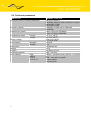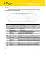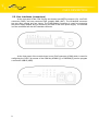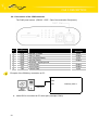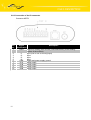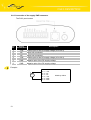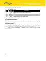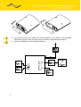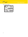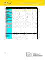
1
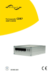
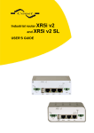
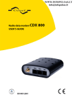
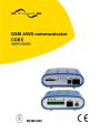
CONTENTS
Contents
1. Safety instructions
2. Description of the CGK 5 GSM key
2.1. General description
2.2. Examples of using
2.3. Description of the individual parts of the CGK 5
2.3.1 Programmable GSM-GPRS module
2.3.2 Control microcontroller
2.3.3 Inputs and outputs
2.4. Technical parameters
2.5. Module state indication
2.6. User interfaces (connectors)
2.6.1 Connection of the COM connector
2.6.2 Connection of the IO connector
2.6.3 Connection of the supply PWR connector
2.6.4 Connection of the USB connector
2.7. Antenna connection
2.8. Power supply
2.9. Standard accessories
2.10. Mechanical external dimensions and mounting recommendations
2.11. Production label
3. CGK5 possibilities – firmware versions
3.1. GSM key application
3.2. AGNES application
3.3. Own JAVA application
3.4. Terminal
4. Reference
5. Links to related products of the manufacturer
5.1. Software
5.2. Products
6. Product disposal informations
7. Complaints procedure
8. Warranty
2
4
5
5
5
5
5
5
5
7
8
9
10
11
13
14
14
14
15
15
18
19
19
19
19
19
20
20
20
20
20
21
23
CONTENTS
Symbols used
Danger – important notice, which may have an influence on the user’s safety or the function of
the device.
Attention – notice on possible problems, which can arise in specific cases.
Information, notice – information, which contains useful advices or interest notice.
Conel s.r.o., Sokolska 71, 562 04 Usti nad Orlici, Czech Republic
Issue in CZ, 05/08/08
3
SAFETY INSTRUCTIONS
1. Safety instructions
Please, observe the following instructions:
1.
The GSM key must be used in compliance with any and all applicable international
and national laws and in compliance with any special restrictions regulating the utilization
of the GSM key in prescribed applications and environments.
2.
To prevent possible injury to health and damage to appliances and to ensure that all
the relevant provisions have been complied with, use only the original accessories
of the Conel company. Unauthorised modifications or utilization of accessories that have
not been approved may result in damage to the GSM key and in a breach of applicable
regulations. Unauthorized modifications or utilization of accessories that have not been
approved may result in the termination of the validity of the guarantee, which, however,
does not affect your legal rights.
3. The GSM key must not be opened. Only the replacement of the SIM card is permitted.
4. Caution! The SIM card could be swallowed by small children.
5. Voltage at the feed connector of the GSM key must not be exceeded.
6. Do not expose the GSM key to extreme ambient conditions. Protect the GSM key against
dust, moisture and high temperature.
7. It is recommended that the GSM key should not be used at petrol stations. We remind
the users of the duty to observe the restrictions concerning the utilization of radio devices
at petrol stations, in chemical plants, or in the course of blasting works in which explosives
are used .
8. When using the GSM key in close proximity of personal medical devices, such as cardiac
pacemakers or hearing aids, you must proceed with heightened caution.
9. If it is in the proximity of TV sets, radio receivers and personal computers, the telephone
may cause interference.
10. It is recommended that you should create an appropriate copy or backup
of all the important settings that are stored in the memory of the device.
4
CGK 5 DESCRIPTION
2. Description of the CGK 5 GSM key
2.1. General description
The CGK 5 is application which contain electronic device TC65 Communicator Java I/O
with programmable GSM/GPRS module Siemens. The CGK 5 module is fitted with a Javabased control software which is used to data or RS232 serial port maintaining, control two
output ports with relays and four optically separated input ports.
Configuration of the CGK 5 module can be carried out through the RS-232 serial
interface by means of the GSM key ADMIN [1] or RADWIN [2] service program.
2.2. Examples of using
•
•
•
•
•
GSM key – gates, motors or barrier controlling by mobile
Alarms SMS detector from connected inputs (sensors)
Technology remote control
GPRS data transmition from industry, measurements and security devices
GSM/GPRS terminal
2.3. Description of the individual parts of the CGK 5
2.3.1 Programmable GSM-GPRS module
Wireless communication in the GSM network is carried out by means of the OEM
module TC65 Java of the SIEMENS company. It has been incorporated directly in the printedcircuit board. The push-out holder of the SIM card reader is accessible from the front panel.
The antenna connector is accessible from the rear panel. The TC65 module is suitable for
communication in both GSM bands 850/900/1800/1900 MHz.
The TC65 module is fitted with two serial interfaces, ASC0 and ASC1. The ASC1
interface has been brought out to the RJ45 connector, which is labelled COM. All the RS232
signals are protected against the over voltage coming through the data cable.
The module TC65 contain interface USB2.0 full speed too, which is take out on USB
connector of type 'B' under marking USB. For this interface it is delivered driver. The USB
interface is not exploited by Java application.
2.3.2 Control microcontroller
The CGK 5 communication module has been fitted with an 8-bit microcontroller that
serves for starting and monitoring the TC65 module operation. The operating microcontroller is
also used for monitoring the state of the supply voltage; if the supply voltage drops below 10,5
V, or 21 V, the operating microcontroller automatically turns off the TC65 module.
The automatic turn-off of the TC65 module also occurs in the event that there is a minimally
power supply 10,8 V, or 21,7 V.
2.3.3 Inputs and outputs
Besides the service data and USB interface, an IO interface has been created
in the CGK 5 module. This is a case of two pairs of signals, where two pairs represent the
relay outputs (O1A+O1B and O2A+O2B), and four represent the separated inputs (I1, I2, I3,
5
CGK 5 DESCRIPTION
I4) with common ground. The input I1 is possible use as counter input for counting with max.
frequency 100 Hz and pulse ratio 10 to 50 %. Inputs and output circuits have been designed
for voltage up to 30 V.
Inputs Ix can use as counter input to counts with maximal frequency 500 Hz and with
duty factor 1:1 for correct pulse recognise. Inputs and outputs circuits are concepts for voltage
to 30 V.
Logical levels limits
LOG0 Vmin
0V
LOG0 Vmax
2V
LOG1 Vmin
4,5 V
LOG1 Vmax
30 V
Relay outputs Ox are acceptable only to static switching, maximally it can use to pulse
generates with non guarantee length. For accurate pulses generate this output isn't
acceptable. Output has parameters Imax = 0,5 A, Vmax = 30 V AC/DC a fmax = frequency of relay
switching it is impossible accurate guarantees, it is considerably depends on software activity.
6
CGK 5 DESCRIPTION
2.4. Technical parameters
GSM module
SIEMENS TC65 Java
Complying with the following standards:
EN 301 511:v9.0.2
EN 55022:1998, A1:2000, A2:2003, Cor:2003
EN ISO/IEC 17025
EN 60 950-1:2001
EGSM900, EGSM 850 a GSM1800,
GSM1900
Class 4 (2W) pro EGSM900
Class 1 (1W) pro GSM1800
-20 oC to +55 oC
-40 oC to +85 oC
10,8 to 15,6 V DC
21,7 to 30 V DC
250 mW
3W
30x90x102 mm
150 g
Din ribbon 35 mm
FME – 50 Ohm
RS232 – connector RJ45 (150 b/s - 115 200 b/
s)
USB – connector of type B
2 relay outputs
4 binary inputs
Frequency bands
Transmission power
Temperature range
Function
Storage
Supply voltage
Consumption
Dimensions
Weight
Fixation
Antenna connector
User interface
7
Reception
Sending
COM
USB2.0
O1, O2
I1, I2, I3, I4
CGK 5 DESCRIPTION
2.5. Module state indication
The front panel of the module is fitted with six indicator lamps (LED) to provide
information about the state of the module.
LED
P
8
Description
Permanently off .................. no power supply
Permanently on (> 1 min)... faulty function
Slowly blinking (9:1)............ the module is not registered in the GSM infrastructure
Slowly blinking (1:9)............ true function
Fast blinking ....................... false PIN
G
Permanently on …………... faulty function
Slightly flashing through ..... sending on the high frequency channel
O1
Light is off…………....the O1A and O1B contacts are disconnect
Light is on………..…. the O1A and O1B contacts are connect
O2
Light is off…………....the O2A and O2B contacts are disconnect
Light is on………..…. the O2A and O2B contacts are connect
I1
Light is off…………... voltage between the I1 and GND contacts is lower than 2 V
Light is on…………....voltage between the I1 and GND contacts is higher than 3 V
I2
Light is off…………... voltage between the I2 and GND contacts is lower than 2 V
Light is on…………....voltage between the I2 and GND contacts is higher than 3 V
I3
Light is off…………... voltage between the I3 and GND contacts is lower than 2 V
Light is on……………voltage between the I3 and GND contacts is higher than 3 V
I4
Light is off…………... voltage between the I4 and GND contacts is lower than 2 V
Light is on…………....voltage between the I4 and GND contacts is higher than 3 V
CGK 5 DESCRIPTION
2.6. User interfaces (connectors)
At the rear panel of the CGK 5 there are situated one MRT9 connector (IO), one RJ12
connector (PWR), and one connector FME, possibly SMA (ANT). The IO-labelled connector
has two relay outputs and four inputs. The PWR-labelled connector is used for connecting
the power supply adapter and for monitoring the state of the main power supply. The antenna
is to be connected into the ANT-labelled connector.
At the front panel of the module there is one RJ45 connector (COM) which is used for
configuring the CGK 5 by means of the GSM key ADMIN [1] or RADWIN [2] service program
a connector USB-B (USB).
9
CGK 5 DESCRIPTION
2.6.1 Connection of the COM connector
The RJ45 panel socket. (RS232 – DCE – Data Communication Equipment)
Pin
Signal
no. identification
1
2
3
4
5
6
7
8
RTS
CTS
DTR
DSR
GND
RXD
CD
TXD
Description
Data flow
direction
Request To Send
Clear To Send
Data Terminal Ready
Data Set Ready
GROUND – signal ground
Receive Data
Carrier Detect
Transmit Data
Input
Output
Input
Output
Output
Output
Input
Example of the GSM key connection to PC:
COM
USB
Cable KD-2
●
10
cable KD2 is connected to PC serial port (example COM1)
GSM key CGK 5
CGK 5 DESCRIPTION
2.6.2 Connection of the IO connector
Connector MRT9
Pin
no.
Signal
identification
1
PWR
2
3
4
5
6
7
8
9
10
I1
I2
I3
I4
GND
O1A
O1B
O2A
O2B
11
Description
Output for feeding other circuits (connected directly to the feeding
system of the modem)
Input (can to use as countig input)
Input
Input
Input
Signal and power supply ground
Relay output
Relay output
Relay output
Relay output
CGK 5 DESCRIPTION
Example of the equipment connected to GSM key IO connector input:
Pin 1 – PWR
Pin 2 – I1
Pin 3 – I2
Pin 4 – I3
Pin 5 – I4
Pin 6 – GND
Pin 7 - O1A
Pin 8 - O1B
Pin 9 - O2A
Pin 10 - O2B
12
GSM key CGK 5
CGK 5 DESCRIPTION
2.6.3 Connection of the supply PWR connector
The RJ12 panel socket
Pin
no.
Signal
identification
Description
1
+UN
Positive pole of the DC supply voltage (10 to 30 V)
2
NC
Signal not connected
3
NC
Signal not connected
4
+UN
Positive pole of the DC supply voltage (10 to 30 V)
5
GND
Negative pole of the DC supply voltage
6
GND
Negative pole of the DC supply voltage
Example:
+
DC
13
Pin 1 – +UN
Pin 2 – NC
Pin 3 – NC
Pin 4 – +UN
Pin 5 – GND
Pin 6 – GND
GSM key CGK 5
CGK 5 DESCRIPTION
2.6.4 Connection of the USB connector
The USB panel socket.
Pin
no.
Signal
identification
Description
1
+ UN
2
D-
Data -
3
D+
Data +
4
GND
Positive pole of the DC supply voltage (5 VDC)
Negative pole of the DC supply voltage
2.7. Antenna connection
The antenna is to be connected to the CGK 5 at the rear panel by means of the FME
connector.
2.8. Power supply
The CGK 45 requires DC supply of +10,8 V to +15,6 V or +21,7 V to +30 V. During
reception, consumption is 250 mW. During data sending, peak consumption is 3 W
To ensure correct functioning, the power supply unit must be able to supply the peak
current of 500 mA.
14
CGK 5 DESCRIPTION
2.9. Standard accessories
1. RJ12 feed connector for the supply voltage lead-in cable.
2. RJ45 connectors used for creating the data cable.
3. Declaration of conformity.
4. Guarantee claim guidelines.
5. Guarantee certificate.
2.10. Mechanical external dimensions and mounting recommendations
For majority applications with built-in modem in switch board it is possible recognize two
sort of environment:
● nopublic and industry environment of low voltage with high interference,
● public environment of low voltage without high interference.
For both this environments it is possible to mount modems to switch board, which
it doesn't need to have no examination immunity or issues in connection with EMC according
to EN 60439-1+A1.
For compliance of EN 60439 - 1 + A1 specification it is necessary observe next
assembly of the modem to the switch - board:
● round antenna we recommended to observe distance 6 cm from cables and metal
surfaces on every side according to next picture because elimination of interferences,
while using external antenna except switch-board it is necessary use fit over-voltage
wardships (lightning arrester) behind mounting of modem on sheet-steel we
recommended to use the external antenna,
15
CGK 5 DESCRIPTION
16
●
singles cables we recommended to bind to the one's bunch according to next picture,
for this way guidee cables reads this limitation:
•
length of the bunch (combination of power supply and data cables) can be
maximum 1,5 m, if length of data cables overreached 1,5 m or in the event of,
that cable lead except switch - board, we recommended to use fit over - voltage
wardships (lightning arrester)
•
with data cable it mustn't lead cable with reticular tension ~ 230 V/50 Hz
•
the signals you conduct by twisted pair to sensors
●
before single connectors it must be well - kept space for handling with cables
at pertinent linking and switching off of single cables,
CGK 5 DESCRIPTION
17
●
for correct function of the modem we recommended to use in switch - board earthing
distribution frame for earth of power supply of modem, data cables and antenna,
●
circuitry of GSM key is on the following pictures.
CGK 5 DESCRIPTION
2.11. Production label
18
CGK5 POSSIBILITIES
3. CGK5 possibilities – firmware versions
3.1. GSM key application
GSM Key HOME version is appropriate for usage at family house and small companies
up to 20 user's. User's administration and configuration is by mobile and SMS messages.
GSM Key PROFI version is appropriate for usage at mid and big companies, offices,
hotels and pensions with higher persons movement (over 20 user's). User's administration
and configuration is by mobile and SMS messages or by SW application GSM key ADMIN [1]
or RADWIN [2].
GSM key CGK-5
version Profi
version Home
Stored list of users
in FLASH
memory
in SIM card
Maximal number of users
300
200
Configurable rights of users for outputs control
yes
no
Switching of outputs status by ringing
yes
no
Event register
yes (1000)
-
3.2. AGNES application
AGNES version is appropriate for industry wireless data transmition. One may simply
imagine the CGK5 module as a protocol converter between the user device (PLC automatic,
PC, data terminal, etc.) and GSM-GPRS infrastructure of a mobile network operator,
it provides the user with possibility to communicate simply between all the systems. Apart from
data transfers via GPRS the CGUK5 module enables ARNEP, Linka-LINE (TCP, UDP),
MBUS-TCP or RDS92 protocols. New protocols, not supported by the communication module
yet, can be implemented according to the customer’s needs.
User's administration and configuration is by SW application GSM key ADMIN [1]
or RADWIN [2]).
3.3. Own JAVA application
To CGK5 is possible upload own JAVA firmware which is created by customer.
This created firmware uses CGK5 hardware. More see [3].
3.4. Terminal
CGK5 is possible delivery without any application, and than used the CGK5 as terminal
which is connected to PC or user's device. Costumer has connection directly with GSM/GPRS
module which can control by standard AT commands via serial line. More about AT
commands see [4].
19
REFERENCE AND LINKS
4. Reference
[1]
Conel s.r.o.: GSM key ADMIN, 2008
[2]
Conel s.r.o.: RADWIN Programme for control AGNES, 2008
[3]
Conel s.r.o.: CGK5 Programmer guide, 2008
[4]
Siemens AG: TC65_ATC_V03.000, 2008
5. Links to related products of the manufacturer
Related products and materials with a reference can be found on the manufacturer’s
website Conel company:
www.conel.cz
There are another links on Siemens company website, TC65 module:
www.siemens.de
www.siemens.com
5.1. Software
RADWIN – the software provides for creation, installation and administration of AGNES
system GPRS data networks.
GSM Key ADMIN - the software provides for administration of GSM Key.
5.2. Products
GSM Datalogger DA4 – GPRS modem.
6. Product disposal informations
The WEEE (Waste Electrical and Electronic Equipment: 2002/96/EC) directive has
been introduced to ensure that electrical/electronic products are recycled using the best
available recovery techniques to minimise the impact on the environment. This product
contains high quality materials and components which can be recycled. At the end of it’s life
this product MUST NOT be mixed with other commercial waste for disposal. Check with the
terms and conditions of your supplier for disposal information.
20
COMPLAINTS PROCEDURE
7. Complaints procedure
Dear customer,
The product you have purchased had passed manufacturer’s tests and its functions
had been checked by our technician before sale. In case any defect shows up during
the guarantee period that prevents normal use we ask you to follow the Complaints procedure
when registering your claim.
To make a possible complaint procedure easier please make sure when taking over
the product your vendor has duly filled in all the relevant parts of the warranty, including date,
seal and signature.
This complaints procedure relates to the purchased products. This complaints
procedure does not relate to the services provided.
Guarantee period of the products
Guarantee period of 24 months from the date of purchase is provided for the device,
source, antenna, data cable and possible accessories. The date of purchase is at the same
time date of takeover.
Registering a claim
It is necessary to register your claim at the vendor where the subject of the complaint
has been purchased. The customer shall present duly filled warranty and the complete subject
of the complaint. Subject of the complaint shall be presented in a condition adequate to that
at the moment of purchase.
Caution!
The vendor is not responsible for keeping default settings or data saved in the subject
of the complaint.
The customer is obliged to clarify the defect or how it is displayed and what claim he
intends to register.
Processing the complaint
The vendor shall provide a free remedy depending on particular conditions, or replace
the subject of the complaint for a new product, or settle the matter in another manner
in compliance with the Civil Code and the Act on consumer’s protection.
As of the moment the claim is registered by the customer and the subject
of the complaint is taken over by the vendor the guarantee period stops running.
The guarantee period continues on the date of takeover of the repaired subject
of the complaint or replaced faultless product by the customer, or should it not be taken over
on the date the customer is obliged to take over the repaired or replaced product. In case
the vendor replaces the subject of the complaint for a new product (including IMEI
replacement) the original subject of the complaint becomes property of the vendor
and the new product becomes property of the purchaser. Since takeover of the new product
a new guarantee period starts. In the cases when the vendor settles the matter after
agreement with the customer by replacement of the subject of the complaint for a faultless
product the new guarantee expires.
1. After 12 months since the replaced product was taken over by the customer.
21
COMPLAINTS PROCEDURE
2. On the date when the original guarantee period (subject of the complaint) would
have expired should it not have been replaced, whichever comes first.
3. The claim is deemed unsubstantiated when the defect is not found by the vendor
processing the complaint or the defect is not covered by the guarantee under
Article 3 of the procedure.
4. In case the claimed defect is not found and functionality is proven to the customer,
the customer is obliged to pay demonstrable cost related to expert assessment
of the claimed defect.
5. In case defect is found when processing the complaint that is not covered by
the guarantee (extra-warranty repair), the vendor shall inform the customer
and the customer shall inform the vendor whether he/she wishes to have
the defect repaired for the price set. A protocol shall be made on exact conditions
of the extra-warranty repair and signed by both the customer and the vendor.
Should the customer not require remedy through an extra-warranty repair under
the conditions, the device shall be returned to him/her after he/she pays
the demonstrable cost of expert assessment.
The guarantee does not cover defects incurred due to
1. Mechanical damage (fall and the like).
2. Use of inadequate, or not recommended sources and other accessories.
3. Connection of the product with non-standard accessories.
4. Installation or use of the product conflicting with the Manual or use for other
purposes than usual for this type.
5. Improper manipulation, or an intervention of unauthorised person or other service
than authorised by the manufacturer.
6. Effects of natural forces (flood, fire etc.) or other local phenomena (storm,
overvoltage and the like).
7. Storage under unauthorised temperatures.
8. Operation in a chemically aggressive environment.
Other conditions
The fact that the subject of the complaint does not conform to parameters set for other
similar product types shall not be considered a fault. To assess whether it is a case of covered
fault the parameters stated in the technical documentation for the product are decisive.
The guarantee expires in any case of changes to the subject of the complaint,
or damaged or otherwise unreadable serial number.
22
WARRANTY
8. Warranty
Device type
Serial number
Guarantee period (months)
Vendor
Date of purchase
Seal of the vendor
23
WARRANTY
1
2
3
4
5
YES - NO
YES - NO
YES - NO
YES - NO
YES - NO
Date of
complaint
registration
Complaint
protocol number
Date of
reception
of the device in
repair shop
Date of finished
repair
Number of repair
sheet
Warranty repair
New serial
number of the
device (IMEI)
Notes
Seal of the
repair shop
24