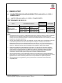
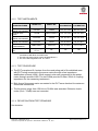
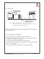
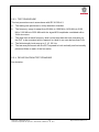
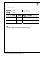
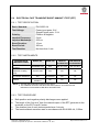
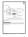
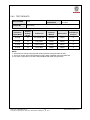
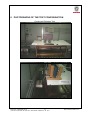
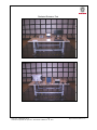
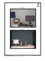
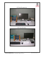
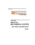
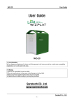
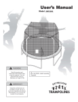
1
CE EMC TEST REPORT
(EN 50155)
REPORT NO.: CE991022C10 R1
MODEL NO.: R10IA3S-VMP1; R10XXXX-XXXXXX
(X=A~Z, a~z, 0~9, Blank or Slash);
GWIN; GWINXX-XXXXXX
(X=A~Z, a~z, 0~9, Blank or Slash)
RECEIVED: Oct. 22, 2010
TESTED: Oct. 27, 2010 ~ Jan. 19, 2011
ISSUED: Jan. 28, 2011
APPLICANT: WinMate Communication INC.
ADDRESS: 9F, Number 111-6, Shing-De Rd., San-Chung City
Taipei 24158, Taiwan, R.O.C
ISSUED BY: Bureau Veritas Consumer Products Services
(H.K.) Ltd., Taoyuan Branch
LAB ADDRESS: No. 19, Hwa Ya 2nd Rd., Wen Hwa Tsuen, Kwei
Shan Hsiang, Taoyuan Hsien 333, Taiwan, R.O.C.
This test report consists of 55 pages in total. It may be duplicated completely for legal use with the
approval of the applicant. It should not be reproduced except in full, without the written approval of
our laboratory. The client should not use it to claim product certification, approval or endorsement by
any government agency. The test results in the report only apply to the tested sample.
Report No.: CE991022C10 R1
1
Cancels and replaces the report No.: CE991022C10 dated Jan. 24, 2011
Report Format Version 4.0.0
Table of Contents
RELEASE CONTROL RECORD..............................................................................................4
1
CERTIFICATION ..........................................................................................................5
2
SUMMARY OF TEST RESULTS ..................................................................................6
2.1
MEASUREMENT UNCERTAINTY ...............................................................................7
3
GENERAL INFORMATION...........................................................................................8
3.1
GENERAL DESCRIPTION OF EUT.............................................................................8
3.2
DESCRIPTION OF TEST MODES...............................................................................8
3.3
DESCRIPTION OF SUPPORT UNITS .........................................................................9
3.3.1
FOR EMISSION TEST .................................................................................................9
3.3.2
FOR IMMUNITY TEST ............................................................................................... 11
4
EMISSION TEST ........................................................................................................13
4.1
CONDUCTED EMISSION MEASUREMENT FOR AUXILIARY A.C. OR D.C.
POWER PORTS.........................................................................................................13
4.1.1
LIMITS FOR AUXILIARY A.C. OR D.C. POWER PORTS..........................................13
4.1.2
TEST INSTRUMENTS................................................................................................14
4.1.3
TEST PROCEDURE ..................................................................................................14
4.1.4
DEVIATION FROM TEST STANDARD ......................................................................14
4.1.5
TEST SETUP .............................................................................................................15
4.1.6
EUT OPERATING CONDITIONS ...............................................................................15
4.1.7
TEST RESULTS .........................................................................................................16
4.2
RADIATED EMISSION MEASUREMENT FOR ENCLOUSE PORT ..........................18
4.2.1
LIMITS OF ENCLOUSE PORT ..................................................................................18
4.2.2
TEST INSTRUMENTS................................................................................................19
4.2.3
TEST PROCEDURE ..................................................................................................20
4.2.4
DEVIATION FROM TEST STANDARD ......................................................................20
4.2.5
TEST SETUP .............................................................................................................21
4.2.6
EUT OPERATING CONDITIONS ...............................................................................21
4.2.7
TEST RESULTS .........................................................................................................22
5
IMMUNITY TEST........................................................................................................24
5.1
GENERAL DESCRIPTION .........................................................................................24
5.2
GENERAL PERFORMANCE CRITERIA DESCRIPTION ..........................................25
5.3
EUT OPERATING CONDITION .................................................................................25
5.4
ELECTROSTATIC DISCHARGE IMMUNITY TEST (ESD) ........................................26
5.4.1
TEST SPECIFICATION ..............................................................................................26
5.4.2
TEST INSTRUMENTS................................................................................................26
5.4.3
TEST PROCEDURE ..................................................................................................27
Report No.: CE991022C10 R1
2
Cancels and replaces the report No.: CE991022C10 dated Jan. 24, 2011
Report Format Version 4.0.0
5.4.4
DEVIATION FROM TEST STANDARD ......................................................................27
5.4.5
TEST SETUP .............................................................................................................28
5.4.6
TEST RESULTS .........................................................................................................29
5.5
RADIATED, RADIO-FREQUENCY, ELECTROMAGNETIC FIELD IMMUNITY TEST
(RS) ............................................................................................................................32
5.5.1
TEST SPECIFICATION ..............................................................................................32
5.5.2
TEST INSTRUMENTS................................................................................................32
5.5.3
TEST PROCEDURE ..................................................................................................33
5.5.4
DEVIATION FROM TEST STANDARD ......................................................................33
5.5.5
TEST SETUP .............................................................................................................34
5.5.6
TEST RESULTS .........................................................................................................35
5.6
ELECTRICAL FAST TRANSIENT/BURST IMMUNITY TEST (EFT) ..........................36
5.6.1
TEST SPECIFICATION ..............................................................................................36
5.6.2
TEST INSTRUMENTS................................................................................................36
5.6.3
TEST PROCEDURE ..................................................................................................36
5.6.4
DEVIATION FROM TEST STANDARD ......................................................................37
5.6.5
TEST SETUP .............................................................................................................37
5.6.6
TEST RESULTS .........................................................................................................38
5.7
SURGE IMMUNITY TEST ..........................................................................................39
5.7.1
TEST SPECIFICATION ..............................................................................................39
5.7.2
TEST INSTRUMENTS................................................................................................39
5.7.3
TEST PROCEDURE ..................................................................................................40
5.7.4
DEVIATION FROM TEST STANDARD ......................................................................40
5.7.5
TEST SETUP .............................................................................................................40
5.7.6
TEST RESULTS .........................................................................................................41
5.8
IMMUNITY TO CONDUCTED DISTURBANCES INDUCED BY RF FIELDS (CS) ....42
5.8.1
TEST SPECIFICATION ..............................................................................................42
5.8.2
TEST INSTRUMENTS................................................................................................43
5.8.3
TEST PROCEDURE ..................................................................................................44
5.8.4
DEVIATION FROM TEST STANDARD ......................................................................44
5.8.5
TEST SETUP .............................................................................................................45
5.8.6
TEST RESULTS .........................................................................................................46
6
PHOTOGRAPHS OF THE TEST CONFIGURATION.................................................47
7
INFORMATION ON THE TESTING LABORATORIES ...............................................55
Report No.: CE991022C10 R1
3
Cancels and replaces the report No.: CE991022C10 dated Jan. 24, 2011
Report Format Version 4.0.0
RELEASE CONTROL RECORD
ISSUE NO.
REASON FOR CHANGE
DATE ISSUED
Original release
NA
Jan. 24, 2011
CE991022C10 R1
Change model
Jan. 28, 2011
Report No.: CE991022C10 R1
4
Cancels and replaces the report No.: CE991022C10 dated Jan. 24, 2011
Report Format Version 4.0.0
1 CERTIFICATION
PRODUCT: 10.4 Rugged Panel PC
BRAND: Winmate
MODEL: R10IA3S-VMP1; R10XXXX-XXXXXX (X=A~Z, a~z, 0~9, Blank or
Slash); GWIN; GWINXX-XXXXXX (X=A~Z, a~z, 0~9, Blank or Slash)
APPLICANT: WinMate Communication INC.
TESTED: Oct. 27, 2010 ~ Jan. 19, 2011
TEST SAMPLE: ENGINEERING SAMPLE
STANDARD: EN 50155: 2007
EN 50121-1: 2006 (2006-07)
EN 50121-3-2: 2006 (2006-07)
EN 55011: 2007+A2: 2007
EN 61000-4-2: 2009
EN 61000-4-3: 2006+A1: 2008
EN 61000-4-4: 2004
EN 61000-4-5: 2006
EN 61000-4-6: 2009
The above equipment (model: R10IA3S-VMP1) has been tested by Bureau Veritas
Consumer Products Services (H.K.) Ltd., Taoyuan Branch. The test record, data
evaluation & Equipment Under Test (EUT) configurations represented herein are true
and accurate accounts of the measurements of the sample’s EMC characteristics
under the conditions specified in this report.
PREPARED BY :
, DATE :
Jan. 28, 2011
, DATE :
Jan. 28, 2011
Joanna Wang / Senior Specialist
APPROVED BY
:
David Liu / Senior Engineer
Report No.: CE991022C10 R1
5
Cancels and replaces the report No.: CE991022C10 dated Jan. 24, 2011
Report Format Version 4.0.0
2 SUMMARY OF TEST RESULTS
The EUT has been tested according to the following specifications:
EMISSION
EN 50155
Reference
Clause(s)
12.2.8.2
Reference
Standard
Test Type
Result
EN 50121-3-2:
2006 (2006-07)
Power line
conducted emission
measurement
PASS
EN 55011:
2007+A2: 2007
Radiated emission
measurement
PASS
Remarks
Meets Limit.
Minimum passing margin is
-21.11dB at 0.205MHz.
Meets Limit.
Minimum passing margin is
-5.82dB at 39.72MHz.
IMMUNITY
EN 50155
Reference
Clause(s)
12.2.7.2
12.2.8.1
12.2.7.3
12.2.7.1
12.2.8.1
Reference
Standard
EN 50121-3-2:
2006 (2006-07)
EN 61000-4-2:
2009
EN 50121-3-2:
2006 (2006-07)
EN 61000-4-3:
2006+A1: 2008
EN 50121-3-2:
2006 (2006-07)
EN 61000-4-4:
2004
EN 50121-3-2:
2006 (2006-07)
EN 61000-4-5:
2006
EN 50121-3-2:
2006 (2006-07)
EN 61000-4-6:
2009
Test Type
Result
Remarks
Electrostatic
discharge immunity
test
PASS
Meets the requirements of
Performance Criterion B
Radio-frequency,
electromagnetic field
immunity test
PASS
Meets the requirements of
Performance Criterion A
Transient burst
susceptibility test
PASS
Meets the requirements of
Performance Criterion A
Surge immunity test
PASS
Meets the requirements of
Performance Criterion A
Radio-frequency,
conducted
disturbances
immunity test
PASS
Meets the requirements of
Performance Criterion A
Report No.: CE991022C10 R1
6
Cancels and replaces the report No.: CE991022C10 dated Jan. 24, 2011
Report Format Version 4.0.0
2.1 MEASUREMENT UNCERTAINTY
Where relevant, the following measurement uncertainty levels have been estimated
for tests performed on the EUT as specified in CISPR 16-4-2:
MEASUREMENT
Conducted emission
Radiated emission
FREQUENCY
9kHz ~ 30MHz
30MHz ~ 1GHz
UNCERTAINTY
2.44dB
4.12dB
This uncertainty represents an expanded uncertainty expressed at approximately the
95% confidence level using a coverage factor of k=2.
Report No.: CE991022C10 R1
7
Cancels and replaces the report No.: CE991022C10 dated Jan. 24, 2011
Report Format Version 4.0.0
3 GENERAL INFORMATION
3.1 GENERAL DESCRIPTION OF EUT
PRODUCT
MODEL NO.
POWER SUPPLY
DATA CABLE
ACCESSORY
DEVICE
10.4 Rugged Panel PC
R10IA3S-VMP1; R10XXXX-XXXXXX (X=A~Z, a~z, 0~9, Blank or
Slash); GWIN; GWINXX-XXXXXX (X=A~Z, a~z, 0~9, Blank or Slash)
24Vdc
0.15m shielded PS/2 cable without core
NA
NOTE:
1. The following models are provided to this EUT.
MODEL
DESCRIPTION
R10IA3S-VMP1
All models are electrically identical,
R10XXXX-XXXXXX (X=A~Z, a~z, 0~9, Blank or Slash)
different model names are for
GWIN
marketing purpose.
GWINXX-XXXXXX (X=A~Z, a~z, 0~9, Blank or Slash)
*The model: R10IA3S-VMP1 was chosen for the final test and presented in the test report.
2. The above EUT information is declared by manufacturer and for more detailed features
description, please refer to the manufacturer's specifications or User's Manual.
3.2 DESCRIPTION OF TEST MODES
The EUT has been pre-tested under following test modes, and test mode 1 was the
worst case for final test.
Test Mode
Test Condition
1
Full system, Run BurnIn test, LAN 1Gbps, 800*600@60Hz
2
Full system, Run BurnIn test, LAN 100Mbps, 800*600@60Hz
3
Full system, Run BurnIn test, LAN 10Mbps, 800*600@60Hz
4
Full system, Run BurnIn test, LAN 1Gbps, 640*480@60Hz
Report No.: CE991022C10 R1
8
Cancels and replaces the report No.: CE991022C10 dated Jan. 24, 2011
Report Format Version 4.0.0
3.3 DESCRIPTION OF SUPPORT UNITS
The EUT has been tested as an independent unit together with other necessary
accessories or support units. The following support units or accessories were used
to form a representative test configuration during the tests.
3.3.1 FOR EMISSION TEST
NO.
PRODUCT
BRAND
MODEL NO.
1
LCD MONITOR
DELL
2407WFPb
2
MODEM
ACEEX
1414V/3
3
MODEM
ACEEX
1414V/3
4
KEYBOARD
DELL
SK-8110
5
DELL
M071KC
DELL
RD1000
DELL
RD1000
TOP WARD
TF-6603A
9
MOUSE
EXTERNAL
HARD DISK
EXTERNAL
HARD DISK
DC POWER
SUPPLY
NOTEBOOK
10
NOTEBOOK
6
7
8
NO.
SERIAL NO.
FCC ID
CN-0FC255-46633FCC DoC Approved
718-0ANS
0401008252
IFAXDM1414
0401008270
IFAXDM1414
MY-05N456-71619FCC DoC Approved
3C1-1801
504008965
FCC DoC Approved
HK-0XM763-72953NA
77Q-001E
HK-0XM763-72953NA
77Q-0001
725942
NA
DELL
D600
F8HBC1S
E2K24CLNS
DELL
PP05L
27368374672
E2K24CLNS
SIGNAL CABLE DESCRIPTION OF THE ABOVE SUPPORT UNITS
1
1.8m braid shielded wire, D-SUB connector, with two cores.
2
1.2m braid shielded wire, DB25 & DB9 connector, w/o core.
3
1.2m braid shielded wire, DB25 & DB9 connector, w/o core.
4
2m foil shielded wire, PS/2 Connector, w/o core.
5
2m foil shielded wire, PS/2 Connector, w/o core.
6
2m shielded cable, terminated with USB connector, with two cores.
7
2m shielded cable, terminated with USB connector, with two cores.
8
NA
9
10m RJ45 UTP cable.
10 10m RJ45 UTP cable.
NOTE:
1. All power cords of the above support units are non-shielded (1.8m).
2. Item 9~10 acted as a communication partners to transfer data.
3. Item 8 was under test table during conducted emission test.
Report No.: CE991022C10 R1
9
Cancels and replaces the report No.: CE991022C10 dated Jan. 24, 2011
Report Format Version 4.0.0
TEST CONFIGURATION
External Hard
Disk x 2
DC
Power
Supply
LCD
Monitor
Modem
EUT
(Power from DC power supply)
Modem
Keyboard
*Test Table
Notebook
Mouse
Notebook
*Kept in a remote area
NOTE: The DC power supply was under test table during conducted emission test.
Report No.: CE991022C10 R1
10
Cancels and replaces the report No.: CE991022C10 dated Jan. 24, 2011
Report Format Version 4.0.0
3.3.2 FOR IMMUNITY TEST
NO.
PRODUCT
BRAND
MODEL NO.
1
LCD MONITOR
DELL
2407WFPb
2
MODEM
ACEEX
1414V/3
3
MODEM
ACEEX
1414V/3
4
KEYBOARD
DELL
RT7D20
5
DELL
M071KC
Sarotech
FHD-354UA
E80L229180019
NA
Sarotech
FHD-354UA
E80L229180007
NA
Terasys
F12-U
A0100214-63f0013
NA
Terasys
F12-U
A0100214-63f0005
NA
10
MOUSE
EXTERNAL
HARD DISK
EXTERNAL
HARD DISK
EXTERNAL
HARD DISK
EXTERNAL
HARD DISK
CAR BATTERY
YUASA
46B24R(S)
NA
NA
11
CAR BATTERY
YUASA
46B24R(S)
NA
NA
12
NOTEBOOK
DELL
PP05L
27368374672
E2K24CLNS
13
HUB
ZyXEL
GS-108B
S090H39011213
NA
14
WIRELESS AP
BUFFALO
WBR2-G54
34059544811648
FDI-04600142-0
6
7
8
9
NO.
SERIAL NO.
FCC ID
CN-0FC255-46633FCC DoC Approved
665-07US
0401008256
IFAXDM1414
0401008250
IFAXDM1414
CN-04N454-37172AQ6-7D20
3BM-B213
504009063
FCC DoC Approved
SIGNAL CABLE DESCRIPTION OF THE ABOVE SUPPORT UNITS
1
1.8m braid shielded wire, D-SUB connector, with two cores.
2
1.2m braid shielded wire, DB25 & DB9 connector, w/o core.
3
1.2m braid shielded wire, DB25 & DB9 connector, w/o core.
4
2m foil shielded wire, PS/2 Connector, w/o core.
5
2m foil shielded wire, PS/2 Connector, w/o core.
6
1.8m shielded cable, terminated with USB connector, w/o core.
7
1.8m shielded cable, terminated with USB connector, w/o core.
8
1.5m shielded cable, terminated with USB connector, w/o core.
9
1.5m shielded cable, terminated with USB connector, w/o core.
10 NA
11 NA
12 3m RJ45 UTP cable.
13 3m RJ45 UTP cable x 2.
14 NA
NOTE:
1. All power cords of the above support units are non-shielded (1.8m).
2. Item 8~9 were for ESD & EFT test only and Item 6~7 for other immunity tests.
3. Item 10~14 acted as a communication partners to transfer data.
Report No.: CE991022C10 R1
11
Cancels and replaces the report No.: CE991022C10 dated Jan. 24, 2011
Report Format Version 4.0.0
TEST CONFIGURATION
(Power from DC power supply)
Modem
LCD
Monitor
EUT
Modem
External Hard
Disk x 2
Keyboard
*Test Table
Car Battery
x2
Wireless
AP
Mouse
HUB
Notebook
*Kept in a remote area
Report No.: CE991022C10 R1
12
Cancels and replaces the report No.: CE991022C10 dated Jan. 24, 2011
Report Format Version 4.0.0
4 EMISSION TEST
4.1 CONDUCTED EMISSION MEASUREMENT FOR AUXILIARY A.C. OR D.C.
POWER PORTS
4.1.1 LIMITS FOR AUXILIARY A.C. OR D.C. POWER PORTS
TEST STANDARD: EN 50121-3-2
PORT
TEST SPECIFICATION
BASIC
STANDARD
REMARKS
TEST SET-UP
Auxiliary supply
sinusoidal a.c. or d.c.
9 kHz ~ 150 kHz
No limits
150 kHz ~ 500 kHz
99 dBμV quasi-peak
500 kHz ~ 30 MHz
93 dBμV quasi-peak
See NOTE 1 & 2
EN 55011
See NOTE 3, 4 & 5
See NOTE 3, 4 & 5
NOTE
1. At present there are no limits for conducted emissions from 9 kHz to 150 kHz. Limiting conducted
emissions from an apparatus will prevent excessive radiated emissions. Experience in this
technique and the relationship between conducted and radiated emissions is necessary in order to
progress this standard in the future.
2. 230 Vac power outlet ports for public use shall offer a power quality, which is sufficient for the use
of intended equipment like PC and mobile telephone chargers. The harmonic distortion in
differential and common mode shall be limited by a sine-filter to < 5 %. The burst and surge
emissions of the outlet have to be limited to the levels of residential equipment according to EN
61000-6-1. AM radio receivers are not intended to be supplied by these power outlets.
3. Wherever applicable the method defined by EN 55011 is to be used. At present the existing
method of measuring conducted emissions (EN 55011) has limitations in terms of voltage and
current rating of coupling networks. In addition the method of measuring voltage has safety
implications for testing high power systems. Limiting conducted emissions from apparatus
connected to external cable systems will prevent excessive radiated emissions.
4. This requirement refers to the industrial limit values but considering they have been defined to
protect radio and TV sets and as the objective is not the same here, the applicable limit for railway
applications have been relaxed by 20 dB to be more representative of potential problems.
5. This requirement is not applicable to power ports which are connected to other dedicated,
compatible ports.
Report No.: CE991022C10 R1
13
Cancels and replaces the report No.: CE991022C10 dated Jan. 24, 2011
Report Format Version 4.0.0
4.1.2 TEST INSTRUMENTS
DESCRIPTION &
MANUFACTURER
Test Receiver
ROHDE & SCHWARZ
RF signal cable
Woken
LISN
ROHDE & SCHWARZ
LISN
ROHDE & SCHWARZ
V-LISN
SCHWARZBECK
Software
ADT
MODEL NO.
SERIAL NO.
DATE OF
CALIBRATION
DUE DATE OF
CALIBRATION
ESCS30
100289
Nov. 23, 2010
Nov. 22, 2011
5D-FB
Cable-HYCO2-01
Dec. 30, 2010
Dec. 29, 2011
ESH2-Z5
100100
Jan. 06, 2011
Jan. 05, 2012
ESH3-Z5
100311
Jul. 08, 2010
Jul. 07, 2011
NNBL 8226-2
8226-142
Jul. 12, 2010
Jul. 11, 2011
ADT_Cond_
V7.3.7
NA
NA
NA
NOTE: 1. The calibration interval of the above test instruments is 12 months and the calibrations are
traceable to NML/ROC and NIST/USA.
2. The test was performed in HwaYa Shielded Room 2.
3. The VCCI Site Registration No. is C-2047.
4.1.3 TEST PROCEDURE
a. The EUT was placed 0.4 meters from the conducting wall of the shielded room
with EUT being connected to the power mains through a line impedance
stabilization network (LISN). Other support units were connected to the power
mains through another LISN. The two LISNs provide 50 Ohm/ 50uH of coupling
impedance for the measuring instrument.
b. Both lines of the power mains connected to the EUT were checked for maximum
conducted interference.
c. The frequency range from 150 kHz to 30 MHz was searched. Emission levels
under (Limit – 20dB) were not recorded.
4.1.4 DEVIATION FROM TEST STANDARD
No deviation.
Report No.: CE991022C10 R1
14
Cancels and replaces the report No.: CE991022C10 dated Jan. 24, 2011
Report Format Version 4.0.0
4.1.5 TEST SETUP
V e r tic a l G r o u n d
Te s t R e c e iv e r
R e fe r e n c e P la n e
40cm
EUT
80cm
L IS N
H o r i z o n ta l G r o u n d
R e fe r e n c e P la n e
N o t e : 1 . S u p p o r t u n i ts w e r e c o n n e c t e d t o s e c o n d L I S N .
2 .B o th o f L IS N s (A M N ) a r e 8 0 c m fr o m E U T a n d a t le a s t 8 0 c m
f r o m o t h e r u n i ts a n d o t h e r m e t a l p l a n e s
For the actual test configuration, please refer to the related item – Photographs of
the Test Configuration.
4.1.6 EUT OPERATING CONDITIONS
a. The EUT ran BurnIn 6.0 test program to enable all functions.
b. The EUT sent “H” patterns to its screen and its screen displayed “H” patterns.
c. The EUT sent “H” patterns to the modems.
d. The EUT communicated messages with the external HDDs.
e. The EUT linked with the notebooks, which acted as a communication partners.
f. Step b ~ c were repeated.
g. The communication partner sent data to EUT by command "PING".
Report No.: CE991022C10 R1
15
Cancels and replaces the report No.: CE991022C10 dated Jan. 24, 2011
Report Format Version 4.0.0
4.1.7 TEST RESULTS
INPUT POWER
24Vdc
6dB BANDWIDTH 9 kHz
ENVIRONMENTAL 23 deg. C, 65% RH,
CONDITIONS
1017 hPa
TESTED BY
PHASE
Line 1
Peter Lin
No
Freq.
[MHz]
Corr.
Factor
(dB)
1
2
3
4
5
6
0.205
0.408
0.615
0.818
1.230
12.074
0.21
0.23
0.25
0.26
0.30
0.42
Reading
Value
[dB (uV)]
Q.P.
77.68
58.69
51.68
47.80
45.89
45.98
Emission
Level
[dB (uV)]
Q.P.
77.89
58.92
51.93
48.06
46.19
46.40
Limit
[dB (uV)]
Margin
(dB)
Q.P.
99.00
99.00
93.00
93.00
93.00
93.00
Q.P.
-21.11
-40.08
-41.07
-44.94
-46.81
-46.60
REMARKS: 1. The emission levels of other frequencies were very low against the limit.
2. Margin value = Emission level - Limit value
3. Correction factor = Insertion loss + Cable loss
4. Emission Level = Correction Factor + Reading Value.
Report No.: CE991022C10 R1
16
Cancels and replaces the report No.: CE991022C10 dated Jan. 24, 2011
Report Format Version 4.0.0
INPUT POWER
24Vdc
6dB BANDWIDTH 9 kHz
ENVIRONMENTAL 23 deg. C, 65% RH,
CONDITIONS
1017 hPa
TESTED BY
PHASE
Line 2
Peter Lin
No
Freq.
[MHz]
Corr.
Factor
(dB)
1
2
3
4
5
6
0.205
0.408
0.615
0.818
1.227
12.281
0.16
0.18
0.20
0.22
0.26
0.46
Reading
Value
[dB (uV)]
Q.P.
75.43
54.71
49.98
46.64
47.39
43.74
Emission
Level
[dB (uV)]
Q.P.
75.59
54.89
50.18
46.86
47.65
44.20
Limit
[dB (uV)]
Margin
(dB)
Q.P.
99.00
99.00
93.00
93.00
93.00
93.00
Q.P.
-23.41
-44.11
-42.82
-46.14
-45.35
-48.80
REMARKS: 1. The emission levels of other frequencies were very low against the limit.
2. Margin value = Emission level - Limit value
3. Correction factor = Insertion loss + Cable loss
4. Emission Level = Correction Factor + Reading Value.
Report No.: CE991022C10 R1
17
Cancels and replaces the report No.: CE991022C10 dated Jan. 24, 2011
Report Format Version 4.0.0
4.2 RADIATED EMISSION MEASUREMENT FOR ENCLOUSE PORT
4.2.1 LIMITS OF ENCLOUSE PORT
TEST STANDARD: EN 50121-3-2
PORT
TEST SPECIFICATION
BASIC
STANDARD
REMARKS
TEST SET-UP
30 MHz ~ 230 MHz 40 dBμV/m quasi-peak
Enclosure
230 MHz ~ 1 GHz
47 dBμV/m quasi-peak
EN 55011
See NOTE 1 & 2
See NOTE 1 & 2
NOTE
1. Measurement distance is 10 m. A measurement distance of 3 m may be used with the limit
increased by 10 dB.
2. Traction converters and auxiliary converters over 50 kVA need not be tested individually but when
the vehicle is tested as a whole in accordance with EN 50121-3-1.
Report No.: CE991022C10 R1
18
Cancels and replaces the report No.: CE991022C10 dated Jan. 24, 2011
Report Format Version 4.0.0
4.2.2 TEST INSTRUMENTS
DESCRIPTION &
MANUFACTURER
MODEL NO.
SERIAL NO.
DATE OF
CALIBRATION
DUE DATE OF
CALIBRATION
Test Receiver
ROHDE & SCHWARZ
ESIB7
100186
Nov. 29, 2010
Nov. 28, 2011
Test Receiver
ROHDE & SCHWARZ
ESIB7
100212
Jul. 22, 2010
Jul. 21, 2011
E4446A
MY48250266
Aug. 11, 2010
Aug. 10, 2011
BILOG Antenna
SCHWARZBECK
VULB9168
9168-148
Apr. 27, 2010
Apr. 26, 2011
BILOG Antenna
SCHWARZBECK
VULB9168
9168-149
Apr. 27, 2010
Apr. 26, 2011
3115
5623
Jul. 13, 2010
Jul. 12, 2011
Preamplifier
Agilent
8447D
2944A10636
Dec. 02, 2010
Dec. 01, 2011
Preamplifier
Agilent
8447D
2944A10637
Dec. 02, 2010
Dec. 01, 2011
Preamplifier
Agilent
8449B
3008A01959
Nov. 03, 2010
Nov. 02, 2011
RF signal cable
Woken
8D-FB
Cable-Hych1-01
Nov. 06, 2010
Nov. 05, 2011
RF signal cable
Woken
8D-FB
Cable-Hych1-02
Nov. 06, 2010
Nov. 05, 2011
ADT_Radiated_
V 7.7.03.6
NA
NA
NA
Antenna Tower(V)
MFA-440
9707
NA
NA
Antenna Tower(H)
MFA-440
970705
NA
NA
Turn Table
DS430
50303
NA
NA
Controller
MF7802
074
NA
NA
Controller
MF7802
08093
NA
NA
HP 160S-29
NA
Feb. 12, 2010
Feb. 11, 2011
Spectrum Analyzer
Agilent
HORN Antenna
EMCO
Software
ADT
RF signal cable
EAST COST Microwave
NOTE: 1. The calibration interval of the above test instruments is 12 months and the
calibrations are traceable to NML/ROC and NIST/USA.
2. The test was performed in HwaYa Chamber 1.
3. The FCC Site Registration No. is 477732.
4. The IC Site Registration No. is IC 7450F-1.
5. The VCCI Site Registration No. is R-1893.
Report No.: CE991022C10 R1
19
Cancels and replaces the report No.: CE991022C10 dated Jan. 24, 2011
Report Format Version 4.0.0
4.2.3 TEST PROCEDURE
a. The EUT was placed on the top of a rotating table 0.8 meters above the ground at
a 10 meters semi-anechoic chamber. The table was rotated 360 degrees to
determine the position of the highest radiation.
b. The EUT was set 10 meters away from the interference-receiving antenna, which
was mounted on the top of a variable-height antenna tower.
c. The antenna is a broadband antenna, and its height is varied from one meter to
four meters above the ground to determine the maximum value of the field strength.
Both horizontal and vertical polarizations of the antenna are set to make the
measurement.
d. For each suspected emission, the EUT was arranged to its worst case and then
the antenna was tuned to heights from 1 meter to 4 meters and the rotatable table
was turned from 0 degrees to 360 degrees to find the maximum reading.
e. The test-receiver system was set to quasi-peak detect function and specified
bandwidth with maximum hold mode when the test frequency is below 1 GHz.
NOTE: The resolution bandwidth of test receiver/spectrum analyzer is 120 kHz for Quasi-peak
detection (QP) at frequency below 1 GHz.
4.2.4 DEVIATION FROM TEST STANDARD
No deviation.
Report No.: CE991022C10 R1
20
Cancels and replaces the report No.: CE991022C10 dated Jan. 24, 2011
Report Format Version 4.0.0
4.2.5 TEST SETUP
For the actual test configuration, please refer to the related item – Photographs of
the Test Configuration.
4.2.6 EUT OPERATING CONDITIONS
Same as 4.1.6.
Report No.: CE991022C10 R1
21
Cancels and replaces the report No.: CE991022C10 dated Jan. 24, 2011
Report Format Version 4.0.0
4.2.7 TEST RESULTS
INPUT POWER
24Vdc
ENVIRONMENTAL
CONDITIONS
24 deg. C, 62% RH,
1019 hPa
TESTED BY
Felix Chen
FREQUENCY
RANGE
DETECTOR
FUNCTION &
BANDWIDTH
30-1000 MHz
Quasi-Peak, 120 kHz
ANTENNA POLARITY & TEST DISTANCE: HORIZONTAL AT 10 M
No.
Freq.
(MHz)
Emission
Level
(dBuV/m)
Limit
(dBuV/m)
Margin
(dB)
Antenna
Height
(m)
Table
Angle
(Degree)
Raw
Value
(dBuV)
Correction
Factor
(dB/m)
1
249.66
36.91 QP
47.00
-10.09
3.50 H
97
23.72
13.20
2
356.57
34.34 QP
47.00
-12.66
2.50 H
1
17.82
16.52
3
409.06
33.12 QP
47.00
-13.88
2.00 H
23
15.17
17.95
4
525.69
37.80 QP
47.00
-9.20
1.50 H
23
17.21
20.58
5
797.84
33.45 QP
47.00
-13.55
1.00 H
186
7.83
25.62
6
891.14
32.62 QP
47.00
-14.38
1.00 H
241
5.51
27.11
REMARKS:
1. Emission level(dBuV/m)=Raw Value(dBuV) + Correction Factor(dB/m)
2. Correction Factor(dB/m) = Antenna Factor (dB/m) + Cable Factor (dB)
3. The other emission levels were very low against the limit.
4. Margin value = Emission level – Limit value.
Report No.: CE991022C10 R1
22
Cancels and replaces the report No.: CE991022C10 dated Jan. 24, 2011
Report Format Version 4.0.0
INPUT POWER
24Vdc
ENVIRONMENTAL
CONDITIONS
24 deg. C, 62% RH,
1019 hPa
TESTED BY
Felix Chen
FREQUENCY
RANGE
DETECTOR
FUNCTION &
BANDWIDTH
30-1000 MHz
Quasi-Peak, 120 kHz
ANTENNA POLARITY & TEST DISTANCE: VERTICAL AT 10 M
No.
Freq.
(MHz)
Emission
Level
(dBuV/m)
Limit
(dBuV/m)
Margin
(dB)
Antenna
Height
(m)
Table
Angle
(Degree)
Raw
Value
(dBuV)
Correction
Factor
(dB/m)
1
39.72
34.18 QP
40.00
-5.82
1.00 V
342
19.66
14.52
2
49.44
33.58 QP
40.00
-6.42
1.00 V
79
19.46
14.12
3
125.25
30.72 QP
40.00
-9.28
1.00 V
358
17.84
12.88
4
249.66
32.43 QP
47.00
-14.57
1.50 V
137
18.56
13.86
5
354.63
33.47 QP
47.00
-13.53
1.00 V
342
16.30
17.17
6
488.76
31.52 QP
47.00
-15.48
3.50 V
1
10.93
20.59
REMARKS:
1. Emission level(dBuV/m)=Raw Value(dBuV) + Correction Factor(dB/m)
2. Correction Factor(dB/m) = Antenna Factor (dB/m) + Cable Factor (dB)
3. The other emission levels were very low against the limit.
4. Margin value = Emission level – Limit value.
Report No.: CE991022C10 R1
23
Cancels and replaces the report No.: CE991022C10 dated Jan. 24, 2011
Report Format Version 4.0.0
5 IMMUNITY TEST
5.1 GENERAL DESCRIPTION
Product Standard:
EN 50121-3-2
EN 61000-4-2
EN 61000-4-3
Basic Standard,
Specification, and
Performance
Criteria:
EN 61000-4-4
EN 61000-4-5
EN 61000-4-6
Electrostatic Discharge – ESD:
±8kV air discharge,
±6kV Contact discharge,
Performance Criterion B
Radio-Frequency Electromagnetic Field
Susceptibility Test – RS:
80-1000 MHz, 20V/m, 80% AM (1kHz),1
800-1000 MHz, 20V/m, 80% AM (1kHz),
1400-2100 MHz, 10V/m, 80% AM (1kHz),
2100-2500 MHz, 5V/m, 80% AM (1kHz),
Performance Criterion A
Electrical Fast Transient/Burst - EFT
±2kV, (5/50 ns, 5kHz)
Performance Criterion A
Surge Immunity Test:
1.2/50μs open circuit voltage, 42Ω, 0.5μF
line to line ±1 kV, line to ground ±2kV
Performance Criterion B
Conducted Radio Frequency Disturbances
Test – CS:
0.15-80 MHz, 10Vrms, 80% AM, 1kHz,
Performance Criterion A
NOTE1: This limit applies to equipment mounted in the passenger compartments, drivers cab or
external to the rolling stock (roof, underframe). For equipment mounted in all other areas a
severity level of 10 V/m may be used
Report No.: CE991022C10 R1
24
Cancels and replaces the report No.: CE991022C10 dated Jan. 24, 2011
Report Format Version 4.0.0
5.2 GENERAL PERFORMANCE CRITERIA DESCRIPTION
According to EN 50121-1 standard, the following describes the general performance
criteria:
A functional description and a definition of performance criteria, during or as a
consequence of the EMC testing, shall be provided by the manufacturer and noted
in the test report, based on the following criteria:
CRITERION A
The apparatus shall continue to operate as intended during and after
the test. No degradation of performance or loss of function is allowed
below a performance level specified by the manufacturer, when the
apparatus is used as intended. The performance level may be
replaced by a permissible loss of performance. If the minimum
performance level or the permissible performance loss is not specified
by the manufacturer, either of these may be derived from the product
description and documentation, and from what the user may
reasonably expect from the apparatus if used as intended.
CRITERION B
The apparatus shall continue to operate as intended after the test. No
degradation of performance or loss of function is allowed below a
performance level specified by the manufacturer, when the apparatus
is used as intended. The performance level may be replaced by a
permissible loss of performance. During the test, degradation of
performance is however allowed. No change of actual operating state
or stored data is allowed. If the minimum performance level or the
permissible performance loss is not specified by the manufacturer,
either of these may be derived from the product description and
documentation, and from what the user may reasonably expect from
the apparatus if used as intended.
CRITERION C
Temporary loss of function is allowed, provided the function is
self-recoverable or can be restored by the operation of the controls.
5.3 EUT OPERATING CONDITION
a.
b.
c.
d.
e.
The EUT ran BurnIn 6.0 test program to enable all functions.
The EUT sent “H” patterns to its screen and its screen displayed “H” patterns.
The EUT sent “H” patterns to the modems.
The EUT communicated messages with the external HDDs.
The EUT linked with the notebook, HUB and wireless AP, which acted as a
communication partners.
f. Step b ~ c were repeated.
g. The communication partner sent data to EUT by command "PING".
h. The touch screen and monitor display functions were evaluated during and after
test.
Report No.: CE991022C10 R1
25
Cancels and replaces the report No.: CE991022C10 dated Jan. 24, 2011
Report Format Version 4.0.0
5.4 ELECTROSTATIC DISCHARGE IMMUNITY TEST (ESD)
5.4.1 TEST SPECIFICATION
Basic Standard:
Discharge Impedance:
Discharge Voltage:
Polarity:
Number of Discharge:
Discharge Mode:
Discharge Period:
EN 61000-4-2
330 ohm / 150 pF
Air Discharge: 2, 4, 8 kV (Direct)
Contact Discharge: 2, 4, 6 kV (Direct / Indirect)
Positive & Negative
Minimum 20 times at each test point
Single Discharge
1 second minimum
5.4.2 TEST INSTRUMENTS
DESCRIPTION &
MANUFACTURER
MODEL NO.
SERIAL NO.
Electronic Discharge Simulator
(KeyTek)
MZ-151EC
0310225
DATE OF
DUE DATE OF
CALIBRATION CALIBRATION
May 26, 2010
May 25, 2011
NOTE: 1. The test was performed in Hwa Ya ESD Room No. 1.
2. The calibration interval of the above test instruments is 12 months and the
calibrations are traceable to NML/ROC and NIST/USA.
Report No.: CE991022C10 R1
26
Cancels and replaces the report No.: CE991022C10 dated Jan. 24, 2011
Report Format Version 4.0.0
5.4.3 TEST PROCEDURE
a. Electrostatic discharges were applied only to those points and surfaces of the
EUT that are accessible to users during normal operation.
b. The test was performed with at least ten single discharges on the pre-selected
points in the most sensitive polarity.
c. The time interval between two successive single discharges was at least 1
second.
d. The ESD generator was held perpendicularly to the surface to which the
discharge was applied and the return cable was at least 0.2 meters from the
EUT.
e. Contact discharges were applied to the non-insulating coating, with the pointed
tip of the generator penetrating the coating and contacting the conducting
substrate.
f. Air discharges were applied with the round discharge tip of the discharge
electrode approaching the EUT as fast as possible (without causing mechanical
damage) to touch the EUT. After each discharge, the ESD generator was
removed from the EUT and re-triggered for a new single discharge. The test was
repeated until all discharges were complete.
g. At least ten single discharges (in the most sensitive polarity) were applied to the
Horizontal Coupling Plane at points on each side of the EUT. The ESD generator
was positioned horizontally at a distance of 0.1 meters from the EUT with the
discharge electrode touching the HCP.
h. At least ten single discharges (in the most sensitive polarity) were applied to the
center of one vertical edge of the Vertical Coupling Plane in sufficiently different
positions that the four faces of the EUT were completely illuminated. The VCP
(dimensions 0.5m x 0.5m) was placed vertically to and 0.1 meters from the EUT.
5.4.4 DEVIATION FROM TEST STANDARD
No deviation.
Report No.: CE991022C10 R1
27
Cancels and replaces the report No.: CE991022C10 dated Jan. 24, 2011
Report Format Version 4.0.0
5.4.5 TEST SETUP
For the actual test configuration, please refer to the related item – Photographs of
the Test Configuration.
NOTE:
TABLE-TOP EQUIPMENT
The configuration consisted of a wooden table 0.8 meters high standing on the Ground Reference
Plane. The GRP consisted of a sheet of aluminum at least 0.25mm thick, and 2.5 meters square
connected to the protective grounding system. A Horizontal Coupling Plane (1.6m x 0.8m) was placed
on the table and attached to the GRP by means of a cable with 940kΩ total impedance. The
equipment under test, was installed in a representative system as described in section 7 of EN
61000-4-2, and its cables were placed on the HCP and isolated by an insulating support of 0.5mm
thickness. A distance of 1-meter minimum was provided between the EUT and the walls of the
laboratory and any other metallic structure.
FLOOR-STANDING EQUIPMENT
The equipment under test was installed in a representative system as described in section 7 of EN
61000-4-2, and its cables were isolated from the Ground Reference Plane by an insulating support of
0.1-meter thickness. The GRP consisted of a sheet of aluminum that is at least 0.25mm thick, and 2.5
meters square connected to the protective grounding system and extended at least 0.5 meters from
the EUT on all sides.
Report No.: CE991022C10 R1
28
Cancels and replaces the report No.: CE991022C10 dated Jan. 24, 2011
Report Format Version 4.0.0
5.4.6 TEST RESULTS
26 deg. C, 50% RH,
1014hPa
ENVIRONMENTAL
CONDITIONS
INPUT POWER
24Vdc
TESTED BY
Andy Chang
TEST RESULTS OF DIRECT APPLICATION
Discharge Level
(kV)
Polarity
Test Point
Contact
Discharge
Air Discharge
Performance
Criterion
2
+/-
1~6
NOTE 1
NA
A
4, 6
+/-
1~6
NOTE 2
NA
B
2, 4, 8
+/-
7 ~ 10
NA
NOTE 1
A
2, 4
+/-
11
NA
NOTE 2
B
8
+/-
11
NA
NOTE 2
B
Description of test point: Please refer to following photos for representative mark only.
TEST RESULTS OF INDIRECT APPLICATION
Discharge Level
(kV)
Polarity
Test Point
Horizontal
Coupling
Plane
Vertical
Coupling
Plane
Performance
Criterion
2, 4, 6
+/-
4 sides
NOTE 1
NOTE 1
A
Description of test point:
2. Rear side
1. Front side
3. Right side
4. Left side
NOTE:
1. There was no change compared with the initial operation during the test.
2. The LAN & WAN connection of EUT broke off during the test, but could self-recover to the initial
operation after the test.
3. The touch screen and monitor display functions were evaluated during and after test.
Report No.: CE991022C10 R1
29
Cancels and replaces the report No.: CE991022C10 dated Jan. 24, 2011
Report Format Version 4.0.0
1
7
2
3
4
8
Report No.: CE991022C10 R1
30
Cancels and replaces the report No.: CE991022C10 dated Jan. 24, 2011
Report Format Version 4.0.0
5
6
9
10
11
Report No.: CE991022C10 R1
31
Cancels and replaces the report No.: CE991022C10 dated Jan. 24, 2011
Report Format Version 4.0.0
5.5 RADIATED, RADIO-FREQUENCY, ELECTROMAGNETIC FIELD IMMUNITY
TEST (RS)
5.5.1 TEST SPECIFICATION
Basic Standard:
Frequency Range:
Field Strength:
Modulation:
Frequency Step:
Polarity of Antenna:
Antenna Height:
Dwell Time:
EN 61000-4-3
80~1000 MHz
800~1000 MHz
1400~2100 MHz
2100~2500 MHz
5, 10, 20 V/m
1 kHz Sine Wave, 80%, AM Modulation
1 % of fundamental
Horizontal and Vertical
1.5 m
3 seconds
5.5.2 TEST INSTRUMENTS
DATE OF
DUE DATE OF
CALIBRATION CALIBRATION
DESCRIPTION &
MANUFACTURER
MODEL NO.
SERIAL NO.
Boonton RF Power Meter
4232A-01-02
107402
Apr. 27, 2010
Apr. 26, 2011
SML03
101499
Nov. 23, 2010
Nov. 22, 2011
LOG ANTENNA
AT5080ANT
303730
NA
NA
Amplifier
60S1G3M1
308049
NA
NA
Amplifier RF TEST
SYSCTRLR
SC1000M1
308057
NA
NA
Amplifier
150W1000
322011
NA
NA
Amplifier
DC7144A
307880
NA
NA
POWER SENSOR
51011-EMC
33105
Apr. 27, 2010
Apr. 26, 2011
POWER SENSOR
51011-EMC
33107
Apr. 27, 2010
Apr. 26, 2011
ADT_RS_V450
NA
NA
NA
R&S Signal Generator
Software
NOTE: 1. The test was performed in Hwa Ya RS Room 1.
2. The calibration interval of the above test instruments is 12 months and the calibrations
are traceable to NML/ROC and NIST/USA.
3. The transmit antenna was located at a distance of 2.0 meters from the EUT. (For
frequency range 80MHz ~ 1GHz).
4. The transmit antenna was located at a distance of 1.5 meters from the EUT. (For
frequency range 1GHz ~ 3GHz).
Report No.: CE991022C10 R1
32
Cancels and replaces the report No.: CE991022C10 dated Jan. 24, 2011
Report Format Version 4.0.0
5.5.3 TEST PROCEDURE
The test procedure was in accordance with IEC 61000-4-3
a. The testing was performed in a fully-anechoic chamber.
b. The frequency range is swept from 80 MHz to 1000 MHz, 1400 MHz to 2100
MHz, 2100 MHz to 2500 MHz with the signal 80% amplitude modulated with a
1kHz sine wave.
c. The dwell time at each frequency shall not be less than the time necessary for
the EUT to be exercised and to respond, but shall in no case be less than 0,5s.
d. The field strength level was up to 5, 10, 20 V/m.
e. The test was performed with the EUT exposed to both vertically and horizontally
polarized fields on each of the four sides.
5.5.4 DEVIATION FROM TEST STANDARD
No deviation.
Report No.: CE991022C10 R1
33
Cancels and replaces the report No.: CE991022C10 dated Jan. 24, 2011
Report Format Version 4.0.0
5.5.5 TEST SETUP
EUT
RF Amplifier
RF Generator
and
control system
Monitoring
system
For the actual test configuration, please refer to the related item – Photographs of
the Test Configuration.
NOTE:
TABLETOP EQUIPMENT
The EUT installed in a representative system as described in section 7 of EN 61000-4-3 was placed
on a non-conductive table 0.8 meters in height. The system under test was connected to the power
and signal wire according to relevant installation instructions.
FLOOR STANDING EQUIPMENT
The EUT installed in a representative system as described in section 7 of EN 61000-4-3 was placed
on a non-conductive wood support 0.1 meters in height. The system under test was connected to the
power and signal wire according to relevant installation instructions.
Report No.: CE991022C10 R1
34
Cancels and replaces the report No.: CE991022C10 dated Jan. 24, 2011
Report Format Version 4.0.0
5.5.6 TEST RESULTS
INPUT POWER
24Vdc
TESTED BY
Nick Liu
ENVIRONMENTAL
CONDITIONS
27 deg. C, 56% RH,
1008 hPa
Frequency
(MHz)
Polarity
Azimuth
Field
Strength
(V/m)
Observation
Performance
Criterion
80-1000
V&H
0, 90, 180, 270
20
NOTE
A
800-1000
V&H
0, 90, 180, 270
20
NOTE
A
1400-2100
V&H
0, 90, 180, 270
10
NOTE
A
2100-2500
V&H
0, 90, 180, 270
5
NOTE
A
* The exclusion band for the transmitter and / or receiver part of the 2.45 GHz RLAN equipment
under test shall extend from 2280 MHz to 2607.675 MHz.
NOTE:
1. There was no change compared with the initial operation during the test.
2. The touch screen and monitor display functions were evaluated during and after test.
Report No.: CE991022C10 R1
35
Cancels and replaces the report No.: CE991022C10 dated Jan. 24, 2011
Report Format Version 4.0.0
5.6 ELECTRICAL FAST TRANSIENT/BURST IMMUNITY TEST (EFT)
5.6.1 TEST SPECIFICATION
EN 61000-4-4
Power input ports: 2 kV
Signal/Control ports : 2 kV
Positive & Negative
5 kHz
5/50 ns
15 ms
300 ms
Not less than 1 min.
Basic Standard:
Test Voltage:
Polarity:
Impulse Frequency:
Impulse Waveshape :
Burst Duration:
Burst Period:
Test Duration:
5.6.2 TEST INSTRUMENTS
DESCRIPTION &
MANUFACTURER
EMC-Partner EFT
Generator
EMC-Partner
Capacitive Coupling
clamp
SERIAL NO.
TRA2000EFT-C1
623
Apr. 30, 2010
Apr. 29, 2011
CN-EFT1000
364
NA
NA
WA
EF1Ada-001
NA
NA
EMC-Partner
GENECS
NA
NA
NA
EFT Adapter WONPRO
Software
DATE OF
DUE DATE OF
CALIBRATION CALIBRATION
MODEL NO.
NOTE: 1. The test was performed in Hwa Ya EFT Room.
2. The calibration interval of the above test instruments is 12 months and the
calibrations are traceable to NML/ROC and NIST/USA.
5.6.3 TEST PROCEDURE
a. Both positive and negative polarity discharges were applied.
b. The length of the “hot wire” from the coaxial output of the EFT generator to the
terminals on the EUT was 0.5 meter.
c. The duration time of each test sequential was 1 minute.
d. The transient/burst waveform was in accordance with EN 61000-4-4, 5/50ns.
Report No.: CE991022C10 R1
36
Cancels and replaces the report No.: CE991022C10 dated Jan. 24, 2011
Report Format Version 4.0.0
5.6.4 DEVIATION FROM TEST STANDARD
No deviation.
5.6.5 TEST SETUP
NOTE:
l length between clamp and the EUT to be tested (should be 0.5 ± 0.05m)
(A) location for supply line coupling
(B) location for signal lines coupling
For the actual test configuration, please refer to the related item – Photographs of the Test
Configuration.
NOTE:
EUTs, whether stationary floor-mounted or table top, and equipment designed to be mounted in other
configurations, shall be placed on a ground reference plane and shall be insulated from it by an
insulating support 0,1 m ± 0,01 m thick. A minimum distance of 0.5m was provided between the EUT
and the walls of the laboratory or any other metallic structure.
Report No.: CE991022C10 R1
37
Cancels and replaces the report No.: CE991022C10 dated Jan. 24, 2011
Report Format Version 4.0.0
5.6.6 TEST RESULTS
INPUT POWER
24Vdc
TESTED BY
Andy Chang
ENVIRONMENTAL
CONDITIONS
Test Level
23 deg. C, 50% RH,
1014 hPa
Polarity
DC power (+)
+/-
2
NOTE
A
DC power (-)
+/-
2
NOTE
A
PE
+/-
2
NOTE
A
DC power (+) − DC power (-) − PE
+/-
2
NOTE
A
LAN 1 (RJ45)
+/-
2
NOTE
A
LAN 2 (RJ45)
+/-
2
NOTE
A
RS232
+/-
2
NOTE
A
VGA
+/-
2
NOTE
A
(kV)
Observation
Performance
Test Point
Criterion
NOTE:
1. There was no change compared with initial operation during and after the test.
2. The touch screen and monitor display functions were evaluated during and after test.
Report No.: CE991022C10 R1
38
Cancels and replaces the report No.: CE991022C10 dated Jan. 24, 2011
Report Format Version 4.0.0
5.7 SURGE IMMUNITY TEST
5.7.1 TEST SPECIFICATION
Basic Standard:
Wave-Shape:
Test Voltage:
Surge Input/Output:
Generator Source
Impedance:
Polarity:
Phase Angle:
EN 61000-4-5
Combination Wave
1.2/50 us Open Circuit Voltage
8 /20 us Short Circuit Current
Power Line : 0.5, 1 kV
L1-L2, L1-PE, L2-PE
2 ohm between networks
12 ohm between network and ground
Positive/Negative
0°/90°/180°/270°
Pulse Repetition Rate: 60 sec.
5 positive and 5 negative at selected points
Number of Tests:
5.7.2 TEST INSTRUMENTS
DESCRIPTION &
MANUFACTURER
Modular Impulse Generator
EMC-Partner Modular
EMC-Partner
Surge Adapter WONPRO
DATE OF
DUE DATE OF
CALIBRATION CALIBRATION
MODEL NO.
SERIAL NO.
MIG0603IN3
352
Aug. 30, 2010
Aug. 29, 2011
CDN UTP8
011
Aug. 30, 2010
Aug. 29, 2011
WA
SU1 Ada-001
NA
NA
NOTE: 1. The test was performed in Hwa Ya Surge Room.
2. The calibration interval of the above test instruments is 12 months and the
calibrations are traceable to NML/ROC and NIST/USA.
Report No.: CE991022C10 R1
39
Cancels and replaces the report No.: CE991022C10 dated Jan. 24, 2011
Report Format Version 4.0.0
5.7.3 TEST PROCEDURE
a. For EUT power supply:
The surge is to be applied to the EUT power supply terminals via the capacitive
coupling network. Decoupling networks are required in order to avoid possible
adverse effects on equipment not under test that may be powered by the same
lines, and to provide sufficient decoupling impedance to the surge wave. The
power cord between the EUT and the coupling/decoupling networks shall be 2
meters in length (or shorter).
b. For test applied to unshielded unsymmetrically operated interconnection lines of
EUT:
The surge is applied to the lines via the capacitive coupling. The coupling /
decoupling networks shall not influence the specified functional conditions of the
EUT. The interconnection line between the EUT and the coupling/decoupling
networks shall be 2 meters in length (or shorter).
c. For test applied to unshielded symmetrically operated interconnection /
telecommunication lines of EUT:
The surge is applied to the lines via gas arrestors coupling. Test levels below the
ignition point of the coupling arrestor cannot be specified. The interconnection
line between the EUT and the coupling/decoupling networks shall be 2 meters in
length (or shorter).
5.7.4 DEVIATION FROM TEST STANDARD
No deviation.
5.7.5 TEST SETUP
Combination
Wave Generator
Coupling &
DecouplingNetwork
AC/DC Power Line (if any)
Signal Line (if any)
EUT
L 2m
For the actual test configuration, please refer to the related item – Photographs of
the Test Configuration.
Report No.: CE991022C10 R1
40
Cancels and replaces the report No.: CE991022C10 dated Jan. 24, 2011
Report Format Version 4.0.0
5.7.6 TEST RESULTS
INPUT POWER
24Vdc
TESTED BY
Andy Chang
ENVIRONMENTAL
CONDITIONS
24 deg. C, 50% RH,
1016 hPa
DC POWER PORT
Phase Angle
Voltage
(kV)
Test Point
0°
90°
180°
270°
Performance
Criterion
0.5
DC power (+) − DC power (-)
+/-
NOTE
NOTE
NOTE
NOTE
A
0.5, 1
DC power (+) − PE
+/-
NOTE
NOTE
NOTE
NOTE
A
0.5, 1
DC power (-) − PE
+/-
NOTE
NOTE
NOTE
NOTE
A
Polarity
NOTE:
1. There was no change compared with initial operation during and after the test.
2. The touch screen and monitor display functions were evaluated during and after test.
Report No.: CE991022C10 R1
41
Cancels and replaces the report No.: CE991022C10 dated Jan. 24, 2011
Report Format Version 4.0.0
5.8 IMMUNITY TO CONDUCTED DISTURBANCES INDUCED BY RF FIELDS
(CS)
5.8.1 TEST SPECIFICATION
Basic Standard:
Frequency Range:
Field Strength:
Modulation:
Frequency Step:
Coupled Cable:
Coupling Device:
EN 61000-4-6
0.15 MHz - 80 MHz
10 Vr.m.s.
1 kHz Sine Wave, 80%, AM Modulation
1 % of fundamental
Power Mains, Unshielded
CDN-M3 (3 wires), Clamp
Report No.: CE991022C10 R1
42
Cancels and replaces the report No.: CE991022C10 dated Jan. 24, 2011
Report Format Version 4.0.0
5.8.2 TEST INSTRUMENTS
DESCRIPTION &
MANUFACTURER
MODEL NO.
FCC POWER LINE COUPLING
M/N:FCC-801
DECOUPLING NETWORK
-M1-25A
FCC POWER LINE COUPLING
M/N:FCC-801
DECOUPLING NETWORK
-M2-25A
FCC POWER LINE COUPLING
M/N:FCC-801
DECOUPLING NETWORK
-M2-25A
FCC POWER LINE COUPLING
M/N:FCC-801
DECOUPLING NETWORK
-M3-25A
FCC POWER LINE COUPLING
M/N:FCC-801
DECOUPLING NETWORK
-M3-25A
FCC SIGNAL LINE POWER LINE
COUPLING DECOUPLING
P/N:FCC-801-T2
NETWORK
FCC SIGNAL LINE POWER LINE
COUPLING DECOUPLING
P/N:FCC-801-T4
NETWORK
FCC SIGNAL LINE POWER LINE
COUPLING DECOUPLING
P/N:FCC-801-T8
NETWORK
P/N:F-203I
EMI Injection Clamp
-23MM
Amplifier Research
75A250AM2
Power Amplifier
BOONTON 4232ARF
4232A-01-02
POWER METER
SERIAL
NO.
DATE OF
DUE DATE OF
CALIBRATION CALIBRATION
03030
Nov. 09, 2010
Nov. 08, 2011
03049
Nov. 09, 2010
Nov. 08, 2011
03050
Nov. 09, 2010
Nov. 08, 2011
03056
Nov. 09, 2010
Nov. 08, 2011
03057
Nov. 09, 2010
Nov. 08, 2011
03030
Nov. 09, 2010
Nov. 08, 2011
03031
Nov. 09, 2010
Nov. 08, 2011
03032
Nov. 09, 2010
Nov. 08, 2011
434
Nov. 09, 2010
Nov. 08, 2011
307804
N/A
N/A
104302
Nov. 12, 2010
Nov. 11, 2011
SML01
102148
Nov. 09, 2010
Nov. 08, 2011
ADT_CS_V37
NA
NA
NA
POWER SENSOR
51011-EMC
30028
Nov. 13, 2010
Nov. 12, 2011
POWER SENSOR
51011-EMC
33029
Nov. 12, 2010
Nov. 11, 2011
R&S Signal generator
Software
NOTE: 1. The test was performed in Hwa Ya CS Room.
2. The calibration interval of the above test instruments is 12 months and the calibrations are
traceable to NML/ROC and NIST/USA.
Report No.: CE991022C10 R1
43
Cancels and replaces the report No.: CE991022C10 dated Jan. 24, 2011
Report Format Version 4.0.0
5.8.3 TEST PROCEDURE
a. The EUT shall be tested within its intended operating and climatic conditions.
b. The test shall be performed with the test generator connected to each of the
coupling and decoupling devices in turn, while the other non-excited RF input
ports of the coupling devices are terminated by a 50-ohm load resistor.
c. The frequency range is swept from 150 kHz to 80 MHz, using the signal level
established during the setting process and with a disturbance signal of 80 %
amplitude. The signal is modulated with a 1 kHz sine wave, pausing to adjust the
RF signal level or the switch coupling devices as necessary. The sweep rate
shall not exceed 1.5 x 10⁻³ decades/s. The step size shall not exceed 1 % of the
start and thereafter 1 % of preceding frequency value where the frequency is
swept incrementally.
d. The dwell time at each frequency shall not be less than the time necessary for
the EUT to be exercised, and able to respond. Sensitive frequencies such as
clock frequency(ies) and harmonics or frequencies of dominant interest, shall be
analyzed separately.
e. Attempts should be made to fully exercise the EUT during testing, and to fully
interrogate all exercise modes selected for susceptibility.
5.8.4 DEVIATION FROM TEST STANDARD
No deviation.
Report No.: CE991022C10 R1
44
Cancels and replaces the report No.: CE991022C10 dated Jan. 24, 2011
Report Format Version 4.0.0
5.8.5 TEST SETUP
NOTE: The EUT clearance from any metallic obstacles shall be at least 0.5m.
All non-excited input ports of the CDNs shall be terminated by 50Ω loads.
For the actual test configuration, please refer to the related item – Photographs of
the Test Configuration.
NOTE:
FLOOR-STANDING EQUIPMENT
The equipment to be tested is placed on an insulating support of 0.1 meters height above a ground
reference plane. All relevant cables shall be provided with the appropriate coupling and decoupling
devices at a distance between 0.1 meters and 0.3 meters from the projected geometry of the EUT on
the ground reference plane.
Report No.: CE991022C10 R1
45
Cancels and replaces the report No.: CE991022C10 dated Jan. 24, 2011
Report Format Version 4.0.0
5.8.6 TEST RESULTS
INPUT POWER
24Vdc
TESTED BY
Andy Chang
ENVIRONMENTAL
CONDITIONS
22 deg. C, 58% RH,
1014 hPa
Frequency
Band (MHz)
Applied
Voltage
(Vrms)
Tested Line
Injection
Method
Observation
Performance
Criterion
0.15-80
10
DC Power line
CDN-M3
NOTE
A
0.15-80
10
LAN cable
Clamp
NOTE
A
0.15-80
10
RS232 cable
Clamp
NOTE
A
0.15-80
10
VGA cable
Clamp
NOTE
A
NOTE:
1. There was no change compared with initial operation during and after the test.
2. The touch screen and monitor display functions were evaluated during and after test.
3. Per client’s requirement, the EUT used shielded LAN cable during the test.
Report No.: CE991022C10 R1
46
Cancels and replaces the report No.: CE991022C10 dated Jan. 24, 2011
Report Format Version 4.0.0
6 PHOTOGRAPHS OF THE TEST CONFIGURATION
Conducted Emission Test
Report No.: CE991022C10 R1
47
Cancels and replaces the report No.: CE991022C10 dated Jan. 24, 2011
Report Format Version 4.0.0
Radiated Emission Test
Report No.: CE991022C10 R1
48
Cancels and replaces the report No.: CE991022C10 dated Jan. 24, 2011
Report Format Version 4.0.0
ESD Test
RS Test
Report No.: CE991022C10 R1
49
Cancels and replaces the report No.: CE991022C10 dated Jan. 24, 2011
Report Format Version 4.0.0
EFT Test (DC power line)
EFT Test (LAN cable)
Report No.: CE991022C10 R1
50
Cancels and replaces the report No.: CE991022C10 dated Jan. 24, 2011
Report Format Version 4.0.0
EFT Test (RS232 cable)
EFT Test (VGA cable)
Report No.: CE991022C10 R1
51
Cancels and replaces the report No.: CE991022C10 dated Jan. 24, 2011
Report Format Version 4.0.0
Surge Test
CS Test (DC power line)
Report No.: CE991022C10 R1
52
Cancels and replaces the report No.: CE991022C10 dated Jan. 24, 2011
Report Format Version 4.0.0
CS Test (LAN cable)
CS Test (RS232 cable)
Report No.: CE991022C10 R1
53
Cancels and replaces the report No.: CE991022C10 dated Jan. 24, 2011
Report Format Version 4.0.0
CS Test (VGA cable)
Report No.: CE991022C10 R1
54
Cancels and replaces the report No.: CE991022C10 dated Jan. 24, 2011
Report Format Version 4.0.0
7 INFORMATION ON THE TESTING LABORATORIES
We, Bureau Veritas Consumer Products Services (H.K.) Ltd., Taoyuan Branch, were
founded in 1988 to provide our best service in EMC, Radio, Telecom and Safety
consultation. Our laboratories are accredited and approved according to ISO/IEC
17025.
Copies of accreditation certificates of our laboratories obtained from approval
agencies can be downloaded from our web site: www.adt.com.tw/index.5.phtml. If
you have any comments, please feel free to contact us at the following:
Linko EMC/RF Lab
Tel: 886-2-26052180
Fax: 886-2-26051924
Hsin Chu EMC/RF Lab
Tel: 886-3-5935343
Fax: 886-3-5935342
Hwa Ya EMC/RF/Safety/Telecom Lab
Tel: 886-3-3183232
Fax: 886-3-3185050
Email: [email protected]
Web Site: www.adt.com.tw
The address and road map of all our labs can be found in our web site also.
--- END ---
Report No.: CE991022C10 R1
55
Cancels and replaces the report No.: CE991022C10 dated Jan. 24, 2011
Report Format Version 4.0.0