1
GENSYS COMPACT
PRIME Paralleling unit
User manual - Technical documentation
A56 Z0 9 0020 B EN
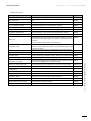
Technical documentation history
Date
Doc. version Comment
June, 2015
A
Initial edition
July, 2015
B
First public release
Preamble
SETTINGS
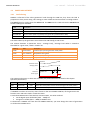
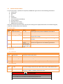
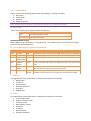
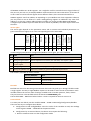
The tables whose header has an orange-coloured background describe settings.
Settings (and readings) that show only in CRE Config, but not on the LCD, feature a purple border in
the HMI chapter as follows:
Setting Label
Description
xxxx
xxx
Can be set in any HMI
xxxx
xxx
Can be set only in CRE Config
The setting content is referred to as [xxxx].
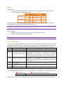
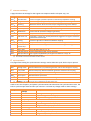
In the illustrations:
Digital inputs and outputs – whether direct or through CANopen – whose assignment is
preset in the CRE Config software application show as follows; the shown position has
no meaning. Only the inputs Remote start and Generator breaker feedback, and the
outputs Fuel and Starter No.1 are mandatory in most cases (for easing reading, they are
shown without selector; the emergency stop input is also shown without selector)
Internal toggles preset through software show as switches with two throws. The code
xxxx or the name of the setting shows above:
assignment
Digital
input
xxxx
assignment
Digital
output
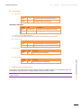
SYMBOLOGY
Denotes a threshold monitoring
Denotes a control loop tuning (three
coefficients G, P, I)
Denotes the need to adjust the
amplitude and offset (center)
CRE Technology believes that all information provided herein is correct and reliable and reserves the
right to update at any time. CRE Technology does not assume any responsibility for its use.
You can download the most up-to-date version of this documentation and different other
documentations relating to GENSYS on our web site http://www.cretechnology.com.
Content
1 Presentation .............................................................................................................................11
1.1
Generator automatic control ................................................................................................. 12
1.2
Generator breaker control..................................................................................................... 12
1.3
Human-Machine Interface ..................................................................................................... 13
1.4
Start and Power management ............................................................................................... 13
1.5
Setting and supervision utility ............................................................................................... 14
1.6
Associated products for remote metering, monitoring and control ........................................ 15
2 Installation ...............................................................................................................................17
2.1
On-desk Ethernet setup ......................................................................................................... 17
2.2
3
3.1
3.2
3.3
3.4
2.1.1
Setting the PC connection .......................................................................................... 17
2.1.2
Changing the GENSYS IP address ................................................................................ 18
2.1.3
Hostname .................................................................................................................. 18
2.1.4
Copyright ................................................................................................................... 18
In-panel installation............................................................................................................... 19
2.2.1
Unpacking .................................................................................................................. 19
2.2.2
Installation................................................................................................................. 19
2.2.3
Wiring the unit ........................................................................................................... 20
2.2.4
Connection diagram ................................................................................................... 24
Operation .................................................................................................................................25
Operating modes................................................................................................................... 25
3.1.1
Manual mode ............................................................................................................ 25
3.1.2
Automatic mode ........................................................................................................ 25
3.1.3
External requests ....................................................................................................... 26
Start sequence ...................................................................................................................... 27
3.2.1
Internal Start sequence .............................................................................................. 27
3.2.2
Idle speed .................................................................................................................. 31
3.2.3
Smoke limiting ........................................................................................................... 31
3.2.4
External auto start module......................................................................................... 32
3.2.5
Power delivery ........................................................................................................... 33
3.2.6
Stop and faults ........................................................................................................... 33
Protections ............................................................................................................................ 34
3.3.1
General ...................................................................................................................... 34
3.3.2
Audio or visual annunciator ....................................................................................... 35
3.3.3
Call for help ............................................................................................................... 35
3.3.4
Emergency stop ......................................................................................................... 35
Potential Alarms/Faults catalog ............................................................................................. 36
3.4.1
Synthesis.................................................................................................................... 38
3.5
Breaker management ............................................................................................................ 39
3.6
Cycles before maintenance ................................................................................................... 39
3.7
Fillings of fluids...................................................................................................................... 40
3.7.1
Presetting .................................................................................................................. 40
3.7.2
Filling up .................................................................................................................... 40
4 Applications..............................................................................................................................41
4.1
First Start .............................................................................................................................. 41
4.2
4.3
4.4
4.5
Synchronization..................................................................................................................... 42
4.2.1
Configuration ............................................................................................................. 42
4.2.2
Tuning ....................................................................................................................... 43
Loading and UNLOADING ramp ............................................................................................. 44
4.3.1
Configuration ............................................................................................................. 44
4.3.2
Tuning ....................................................................................................................... 44
Power management .............................................................................................................. 45
4.4.1
Load sharing .............................................................................................................. 45
4.4.2
Fallback plans ............................................................................................................ 46
4.4.3
Load-dependent start/stop ........................................................................................ 49
4.4.4
Automatic frequency/voltage centering ..................................................................... 52
Additional capabilities ........................................................................................................... 53
4.5.1
Start by static paralleling............................................................................................ 53
4.5.2
Load shedding ............................................................................................................ 55
5 Commissioning .........................................................................................................................59
5.1
Introduction .......................................................................................................................... 59
5.2
Analog speed governor output .............................................................................................. 60
5.3
Analog AVR (Auto Voltage Regulator) control ........................................................................ 62
5.4
Speed/voltage controlled by contacts/pulses ........................................................................ 64
5.5
6
6.1
5.4.1
Setup ......................................................................................................................... 64
5.4.2
Speed calibration procedure ...................................................................................... 65
5.4.3
Voltage calibration procedure .................................................................................... 66
Tests ..................................................................................................................................... 67
5.5.1
Individual check ......................................................................................................... 67
5.5.2
Island mode check ..................................................................................................... 68
Human-Machine Interface........................................................................................................69
Security and operations through the front panel ................................................................... 69
6.1.1
Security level and password ....................................................................................... 69
6.1.2
HMI status ................................................................................................................. 70
6.1.3
Navigation in LCD ....................................................................................................... 70
6.1.4
Edition ....................................................................................................................... 70
6.2
Supervision ........................................................................................................................... 71
6.3
Web server............................................................................................................................ 71
6.4
DISPLAY Menu ....................................................................................................................... 72
6.5
CONFIGURATION menu ......................................................................................................... 76
6.6
SYSTEM menu ....................................................................................................................... 84
7 Communication buses ..............................................................................................................89
7.1
Modbus TCP .......................................................................................................................... 89
7.2
7.3
7.1.1
Capabilities ................................................................................................................ 89
7.1.2
Configuration ............................................................................................................. 89
7.1.3
Description ................................................................................................................ 89
CANopen extension modules................................................................................................. 92
7.2.1
Hardware................................................................................................................... 92
7.2.2
Configuration ............................................................................................................. 93
7.2.3
Mapping .................................................................................................................... 93
J1939 Communication ........................................................................................................... 94
7.3.1
Overview ................................................................................................................... 94
7.3.2
Measuring points and positions ................................................................................. 94
7.3.3
Faults ......................................................................................................................... 99
7.3.4
Controls ................................................................................................................... 100
8 Resources for setup & maintenance .......................................................................................101
8.1
File transfer ......................................................................................................................... 101
8.2
8.3
8.4
8.1.1
GENSYS -> PC file transfer ........................................................................................ 101
8.1.2
PC -> GENSYS file transfer ........................................................................................ 102
8.1.3
Update firmware ..................................................................................................... 102
Text file description ............................................................................................................. 102
8.2.1
Variable naming ....................................................................................................... 102
8.2.2
Text file description ................................................................................................. 103
I/O lines .............................................................................................................................. 105
8.3.1
Digital inputs............................................................................................................ 105
8.3.2
Digital outputs ......................................................................................................... 107
8.3.3
Analog inputs ........................................................................................................... 111
Relay outputs ...................................................................................................................... 113
8.4.1
Breaker working modes ........................................................................................... 113
8.4.2
Settings of pulses ..................................................................................................... 114
8.4.3
Related outputs ....................................................................................................... 114
9 Maintenance ..........................................................................................................................115
9.1
Upgrading the software ....................................................................................................... 115
9.2
Adding a custom HMI language ........................................................................................... 115
9.3
Troubleshooting .................................................................................................................. 115
10 APPENDICES ...........................................................................................................................119
STANDARDS FOR GENERATORS
PROTECTION AGAINST SHORT CIRCUITS
CAN BUS GOOD PRACTICES
MTU J1939 Communications
CONTROL LOOP TUNING
Index
Aggregate Bus System ......................................................................................................................11
Information page (button) ...............................................................................................................13
Power management (general) ..........................................................................................................13
Dynamic paralleling (general) ..........................................................................................................13
Static paralleling (general) ...............................................................................................................13
CRE Config (hook up) ........................................................................................................................14
Text file (deployment) ......................................................................................................................14
Unmanned usage .............................................................................................................................15
Hostname.........................................................................................................................................18
Battery .............................................................................................................................................22
Biphase (installation) .......................................................................................................................23
Current transformer (2 phases) ........................................................................................................23
Modes ..............................................................................................................................................25
Start (Manual) ..................................................................................................................................25
Remote commands ..........................................................................................................................26
Start-stop cycle ................................................................................................................................27
Crank ................................................................................................................................................27
Start .................................................................................................................................................27
Protections (engine) .........................................................................................................................30
Multiple starters ..............................................................................................................................31
Smoke limiting .................................................................................................................................31
Auto start module ............................................................................................................................32
Inhibition on start ............................................................................................................................32
Protections (general) ........................................................................................................................34
Severity ............................................................................................................................................34
Latching alarms ................................................................................................................................35
Horn .................................................................................................................................................35
Annunciators ....................................................................................................................................35
Reverse power .................................................................................................................................36
ANSI codes .......................................................................................................................................36
kW overload protection ...................................................................................................................36
Breaker failure .................................................................................................................................36
Battleswitch .....................................................................................................................................38
Clearing the alarms/faults ................................................................................................................38
Breaker signal discordance ...............................................................................................................39
Maintenance schedule .....................................................................................................................39
Programmed maintenance ...............................................................................................................39
Running cycles..................................................................................................................................39
Dead bus ..........................................................................................................................................41
Production request ..........................................................................................................................41
Election among generators ..............................................................................................................41
Synchronization of networks............................................................................................................42
Auto-sync .........................................................................................................................................42
Staged loading..................................................................................................................................44
Load ramp (principle) .......................................................................................................................44
Soft transfer .....................................................................................................................................44
Hard transfer ....................................................................................................................................44
Bumpless transfer ............................................................................................................................44
Island mode......................................................................................................................................45
Dynamic paralleling..........................................................................................................................45
Paralleling ........................................................................................................................................45
Uneven generator (load) ..................................................................................................................45
Unbalanced load protection .............................................................................................................45
Fallback ............................................................................................................................................48
Droop ...............................................................................................................................................48
Help call ...........................................................................................................................................48
Prealarm ..........................................................................................................................................48
Call for help ......................................................................................................................................48
Load demand ...................................................................................................................................49
Phasing in/out generators ................................................................................................................49
Start/stop a generator .....................................................................................................................49
Load/unload a generator .................................................................................................................49
Standard control of the load ............................................................................................................49
Peer-to-Peer communications..........................................................................................................49
Unload gen if LDSS OK ......................................................................................................................49
Priority generator.............................................................................................................................51
Frequency centering.........................................................................................................................52
Voltage centering .............................................................................................................................52
De-drooping (principle) ....................................................................................................................52
Optimization (centering) ..................................................................................................................52
Start with override ...........................................................................................................................53
Static synchronizing .........................................................................................................................53
Black start synchronization ..............................................................................................................53
Emergency start ...............................................................................................................................53
Static paralleling...............................................................................................................................53
Synchronization of excitation ...........................................................................................................54
Load shedding ..................................................................................................................................55
Load curtailment ..............................................................................................................................55
Load reduction .................................................................................................................................55
Non essential loads ..........................................................................................................................55
Non emergency loads .......................................................................................................................55
Phasing out the loads .......................................................................................................................55
Scaling (speed out) ...........................................................................................................................60
Speed demand .................................................................................................................................60
Scaling (AVR out)..............................................................................................................................62
Speed demand (pulses) ....................................................................................................................64
Load sharing .....................................................................................................................................65
Password ..........................................................................................................................................69
Access rights (HMI) ...........................................................................................................................69
Inhibition of keys and buttons .........................................................................................................70
Monitoring (CRE Config) ...................................................................................................................71
Web server .......................................................................................................................................71
Electrical metering ...........................................................................................................................72
Synchroscope ...................................................................................................................................73
Engine metering ...............................................................................................................................73
Biphase (setting) ..............................................................................................................................76
Potential transformer ......................................................................................................................76
Current transformer (generator) ......................................................................................................76
Speed (alternative)...........................................................................................................................78
Data logging .....................................................................................................................................82
Information page .............................................................................................................................87
Access rights (via Modbus) ...............................................................................................................90
Bit fields ...........................................................................................................................................90
Log file............................................................................................................................................101
Text file (transfer) ..........................................................................................................................101
Clearing the log ..............................................................................................................................101
Text file (description) .....................................................................................................................102
Validity of digital input ...................................................................................................................105
Calibration......................................................................................................................................111
Accuracy (analog inputs) ................................................................................................................111
Undervoltage coil ...........................................................................................................................114
UV coil ............................................................................................................................................114
No voltage coil ...............................................................................................................................114
Shunt coil (MX ) ..............................................................................................................................114
MN coil ...........................................................................................................................................114
MX coil ...........................................................................................................................................114
ISO standards .................................................................................................................................119
Black start (definition)....................................................................................................................119
Hunting ..........................................................................................................................................128
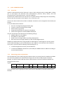
1
PRESENTATION
GENSYS Compact is a panel mounting electronic unit meant for the control of a fuel single, two or threephase low-voltage generator.
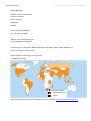
The Prime model is mainly designed to control a generator that operates in an aggregate of generators
(up to 32 multiple sets with prime mover and standby sets) in parallel (island mode) with load sharing.
Various generator powers are specified for various usages. Refer to Appendix: Standard for generators.
GENSYS Compact capabilities include:
Start and monitoring of the engine (three 2-wire resistor inputs)
Acquisition of the engine speed and the generator AC currents and voltages
Generator electrical protections
PID control in various modes (isochronous, speed and voltage droop, frequency/volt centering)
Control of actuators; it is compatible with most speed governors (ESG) and AVR regulators
Synchronization before coupling
Extension by CANopen units (Wago, Beckhoff, VIPA, etc): up to 32 extra digital inputs and 32
extra digital outputs
Link to a PLC or a SCADA via Modbus TCP
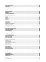
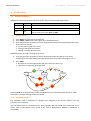
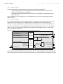
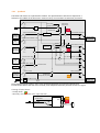
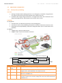
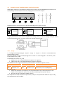
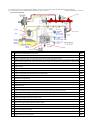
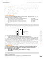
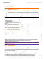
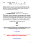
Chapter: Presentation
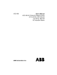
In this typical setup, three GENSYS Compact units communicate over a CAN bus to control three
generators in parallel:
Heterogeneous aggregate of generators in island mode can be controlled by GENSYS Compact
modules. It is preferred that the alternator winding pitches be identical. In any case, all the generators
must be controlled by similar GENSYS COMPACT PRIME units.
The engine-generator may have an Electronic Control Unit with CAN J1939 interface. J1939 and
CANopen interfaces can coexist – on a second CAN media – provided they use the same bit-rate.
According to the settings, the engine speed is measured by a magnetic pick-up, derived from the AC
frequency or provided over a J1939 CAN bus.
Limits on overall active and reactive powers: 65,535 kW and 65,535 kVAR.
11
A56 Z0 9 0020 B EN
UseR manual – technical documentation
1.1
A56 Z0 9 0020 B EN
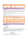
GENERATOR AUTOMATIC CONTROL
Two separate cascade control systems are used:
Primary control (GENSYS)
Secondary control
Speed
ESG control
ECU or ESG
Voltage
AVR control
AVR
The generated voltages and currents are measured in true RMS and used to calculate the load demand
across the aggregate. The synchronization requests and load demand drive the primary control which,
according to its configuration:
produces an analog signal Speed out+, sends pulses “+/- f” to digital outputs or writes to J1939
bus.
produces an analog signal AVR out+ or sends pulses “+/- U” to digital outputs.
1.2
GENERATOR BREAKER CONTROL
When GENSYS has synchronized the generator and bus bar, it closes the breaker relays (coupling);
this can also be done manually: locally (front button) or remotely (if configured so). All the related
digital inputs and outputs are configurable.
Chapter: Presentation
Two coils can be controlled simultaneously.
12
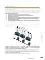
1.3
HUMAN-MACHINE INTERFACE
Back-lit auto-off LCD
The led blinks after a fault arises.
Acknowledged by pressing the lower button
The led blinks after an alarm arises.
Acknowledged by pressing the lower button
Press to switch to automatic mode. Led is lit
when this mode is activated
Press to switch to test mode (starts the gen. &
closes breaker). Led is lit when mode is activated
Press
to access:
.the Fault page if new fault occurred (Fault blinks)
.the Alarm page if new alarm occurred (Al. blinks)
.pages with 2 statuses (Power and Engine) and 10
readings of special interest.
Press again to return.
In manual mode:
Led Gen. ready
Closes/opens generator
breaker
Navigation/Edition
(see below)
Breaker status led
(lit when closed)
Manual mode
Starts/ stops
generator
Bus status led
(lit when live)
Keyboard:
Navigation mode
Edition mode
Cyclic navigation through menu & settings list Used to change the value of a setting. Hold down to change
faster
Cyclic navigation through pages when an item –
Shift
is selected in a menu and validated
Used with to in/decrease LCD luminosity
Used with to adjust LCD contrast
Used with
Esc
Enter
1.4
Return to parent menu (3 times to home) or
preceding menu
Page opening / switch to Edition mode
When in manual mode and breaker is open, used with to
increase/decrease:
speed command on Speed control page
voltage command on Voltage control page
Chapter: Presentation
Keys
to reset alarms and faults
Setting change rejection and return to the Navigation mode
Validation of the new setting and return to Navigation mode
START AND POWER MANAGEMENT
GENSYS units in an aggregate share information through CAN bus communication. Various start
strategies can be implemented to match your needs:
In dynamic paralleling, the generators are selectively started and synchronized to the
already running units. Then they can be stopped and restarted according to the load demand
(“Load-Dependent Start-Stop”).
In static paralleling (emergency start), the generators are started simultaneously and the
warm-up is by-passed.
13
A56 Z0 9 0020 B EN
UseR manual – technical documentation
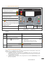
1.5
A56 Z0 9 0020 B EN
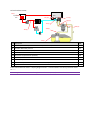
SETTING AND SUPERVISION UTILITY
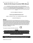
A Windows™ PC with the software application CRE Config 2.50 or later must be connected on the
rear Ethernet socket, generally via a switch in a star network:
This allows you to preset all the GENSYS units when they are on desk: a text file that reflects the first
GENSYS unit’s configuration can serve as a template to deploy the setup to the other GENSYS units in
the cluster. The CRE Config multi-tabbed interface makes it easy.
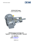
Once all GENSYS units are mounted, CRE Config can be used to set them up and monitor the generators.
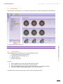
The CRE Config features a Scada section that can be used in particular as an event console to GENSYS:
14
Information
display
Event
console
CRE Config/Scada
Information
Power
Engine
Prod request 1
Mode
AUTO
Event
logger
Chapter: Presentation
GENSYS
Label
Variable
State
0h00
Breaker fault
xxxx
1
Label
Variable
Value
Prod request
xxxx
1
xxxx
AUTO
Mode
2,000
2
1
Time
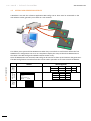
1.6
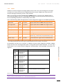
ASSOCIATED PRODUCTS FOR REMOTE METERING, MONITORING AND CONTROL
The readings, and alarms-faults raised by GENSYS can be transmitted over a wired Ethernet network
through the CRE Technology boxes BSD Plus (see preceding illustration; it embeds a website) or
BSD2.0 (illustrated herein; it uses the IaaS cloud technology):
The data server stores the data and forwards e-mails to notify alarms-faults (SMTP).
Antennas provide wireless capabilities:
3G/GSM/GPRS (insert a SIM card into the slot); SMS service is supported by BSD Plus
GPS (geo-localization; geo-fencing is supported by BSD 2.0).
Chapter: Presentation
The alarms-faults can be remotely reset, and the generator started in any mode. The writing rights
are those defined for Modbus TCP. Trend analysis and tunneling (direct connection to GENSYS) are
available with BSD 2.0. Refer to the dedicated manual.
15
A56 Z0 9 0020 B EN
A56 Z0 9 0020 B EN
2
user manual - technical documentation
INSTALLATION
2.1
ON-DESK ETHERNET SETUP
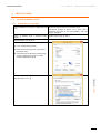
2.1.1
Setting the PC connection
Connect GENSYS to a PC with a 100 Ethernet
cord
Direct connection to PC: use a crossover cord.
Power up GENSYS using a stabilized power
supply
Power supply range: 8…35VDC
Connection through a switch: use a direct cord; a
crossover cord such as 3-m long A53W1 is OK if the
switch manages it.
Open Windows control panel
Click:
Local network (Windows XP)
Network and Sharing Center / View status
(Windows Vista)
Open Network and Sharing Center/Change
adapter settings/(Connection to) LAN/
Properties (Windows 7 & 8)
Click Parameters (Windows XP) or Properties
(Windows Vista or 7 or 8)
Chapter: Installation
17
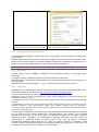
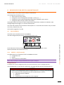
Select TCP/IP or TCP/IP v4, and click Properties
Enter a PC address that differs from the one of
the GENSYS only by the last number, & click OK
2.1.2
Last number: 0 … 255; avoid 0 and 255 as they are
often taken for other purposes
Changing the GENSYS IP address
To change GENSYS IP address, in CRE Config (or on LCD), navigate to “System/Network configuration
(resp. About)”.
GENSYS supports the DHCP function: in this case, GENSYS must be connected on a network with a
DHCP server. During the power-on sequence, GENSYS is assigned an IP address by the DHCP server. If
DHCP process fails, the fixed IP address is used (factory setting: 192.168.11.1).
Note: Contact your network administrator to configure your router and module(s) to your needs.
2.1.3
Hostname
You can assign an alias to GENSYS, in addition to the IP address; enter it in CRE Config to get
connected.
To change this alias, in CRE Config navigate to System/Network configuration.
Maximum length: 16 characters. With Windows, the last character defines the type of service (0 is
the usual value).
Allowed characters: reduced ANSI set; "-" and "." are allowed except at the start and end.
2.1.4
Copyright
GENSYS Ethernet communication uses the open source lwIP TCP-IP stack. Read copyright/disclaimer
below. More details on lwIP Web site: http://savannah.nongnu.org/projects/lwip/
Copyright © 2001-2004 Swedish Institute of Computer Science. All rights reserved.
Redistribution and use in source and binary forms, with or without modification, are permitted provided that
the following conditions are met:
1. Redistributions of source code must retain the above copyright notice, this list of conditions and the following
disclaimer.
2. Redistributions in binary form must reproduce the above copyright notice, this list of conditions and the
following disclaimer in the documentation and/or other materials provided with the distribution.
3. The name of the author may not be used to endorse or promote products derived from this software without
specific prior written permission.
THIS SOFTWARE IS PROVIDED BY THE AUTHOR ``AS IS'' AND ANY EXPRESS OR IMPLIED WARRANTIES, INCLUDING,
BUT NOT LIMITED TO, THE IMPLIED WARRANTIES OF MERCHANTABILITY AND FITNESS FOR A PARTICULAR
PURPOSE ARE DISCLAIMED. IN NO EVENT SHALL THE AUTHOR BE LIABLE FOR ANY DIRECT, INDIRECT,
INCIDENTAL, SPECIAL, EXEMPLARY, OR CONSEQUENTIAL DAMAGES (INCLUDING, BUT NOT LIMITED TO,
PROCUREMENT OF SUBSTITUTE GOODS OR SERVICES; LOSS OF USE, DATA, OR PROFITS; OR BUSINESS
INTERRUPTION) HOWEVER CAUSED AND ON ANY THEORY OF LIABILITY, WHETHER IN CONTRACT, STRICT
LIABILITY, OR TORT (INCLUDING NEGLIGENCE OR OTHERWISE) ARISING IN ANY WAY OUT OF THE USE OF THIS
SOFTWARE, EVEN IF ADVISED OF THE POSSIBILITY OF SUCH DAMAGE.
user manual - technical documentation
A56 Z0 9 0020 B EN
2.2
IN-PANEL INSTALLATION
The unit is designed for panel mounting, which provides user with access only to the front panel.
WARNING
THE UNIT IS NOT GROUNDED
Take all measures against Electronic Static Discharges.
Do not try to open the unit.
Failure to follow these instructions may damage the unit
Environmental requirements:
Operating temperature: -30°C (-22°F) … 70°C (158°F); LCD display slows down a bit under -5°C
(23°F). Avoid direct exposure to the sun
Storage temperature: -40°C (-40°F) … 80°C (176°F)
Altitude: up to 2,000 m (6,561 ft); on higher altitudes, recommended max. AC voltage : 100VAC
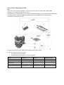
2.2.1
Unpacking
Make sure the packaging contains:
the unit
four caps + screws packaged apart
a delivery bill
Unpack and keep the packaging in event of return.
Make sure the unit does not show scratches or visible defaults. Otherwise describe them on the RMA
sheet (downloadable from CRE technology Web site).
Installation
Chapter: Installation
2.2.2
Preparation
1. Cut out the panel to 220x160 mm minimum (8.7 in x 6.3 in)
2. Make sure the cut-out is smooth and clean
Mounting
0
Tool: cross-head screwdriver size 1
X4
2
Pass the unit through the panel
2
In the rear, cover each of the four
spacers with a cap
3
Screw a cap against the panel
4
Repeat on the diagonally opposite
spacer
5
Repeat on the other diagonal and
tighten equally (do not overtighten)
3
+
4x11 mm
(0.16x0.42 in)
9 mm
0.35 in
23 mm
0.9 in
GENSYS
1
1
∢
19
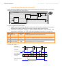
2.2.3
Wiring the unit
Tool: insulated screwdriver Ø2.5 mm (0.1 in), tightening torque: 0.8 Nm (7 lb-in) max.
Accessories: 4, 5, 6, 8, 15 & 18-terminal cable connectors, protective gloves, carpet if the floor is wet.
WARNING
THE UNIT IS NOT PROTECTED
Use external fuses:
Bus bar and Generator phases: 100mA/600VAC
Battery positive: 5A/40VDC
Install the fuses as near as possible the unit, in a place easily accessible to the user.
The disconnection device must NOT be fitted in a flexible cord.
Failure to follow these instructions may damage the unit
DANGER
!l
l
HAZARD OF ELECTRIC SHOCK,
EXPLOSION OR ARC FLASH
The unit must only be installed and serviced by qualified electrical personnel
Apply appropriate personal protective equipment (PPE) & follow safe electrical work practices
Turn off power before installing or removing fuses, and before installing the unit
Use a properly rated voltage sensing device to confirm the power is off
Do not use renewable link fuses in fused switch
Failure to follow these instructions will result in death or serious injury
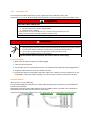
General procedure
1. Make sure the cable connectors are NOT plugged
2. Take on protective gloves
3. Connect the wires on each cable connector in accordance with the National Wiring Regulations
4. Plug each cable connector onto the related connector
5. Plug a direct Ethernet cord (RJ45, male-male, 100 m max., 100; a crossover cable such as 3-m
long A53W1 is OK if the switch manages it or if the link to PC is direct) and lock the rear door.
Recommendations
Wires section: 2.5 mm² (AWG13).
To avoid ElectroMagnetic Interferences, shield cables appropriately; for CAN bus, see the Appendix
CAN bus Good practices.
Segregation: keep the power cable separate from the CAN bus cables. The latter can be installed in
the same duct as the low level DC I/O wires (under 10V).
If power & communication cables have to cross each other, do it at right angles to avoid crosstalk:
user manual - technical documentation
A56 Z0 9 0020 B EN
Breaker commands
AC voltages
CT inputs
8-35VDC-Digital I/Os
Analog inputs
CAN2-Speed-AVR-CAN1-pickup
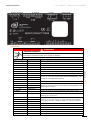
Upper blocks
!l
EXPOSED TERMINALS l
DANGER
Failure to follow this instruction will result in death, serious injury or equipment damage
Block and mark
Description
Note
Breaker commands
Normally open. Breaking capacity: 5A, 240VAC
Relay 1
Relay 1 +
Relay 1 –
Relay 2
Relay 2 +
Relay 2 –
AC voltages
100-480VAC, measure range: 35 … 75HZ, 100mA max; accuracy: 1% fsd
N
Bus N
Option
L3
Bus L3
These lines must be protected externally with 100mA/600VAC fuses.
L2
Bus L2
Use two PTs of 2VA (Phase-to-phase)
L1
Bus L1
N
Generator N
Option
L3
Generator L3
These lines must be protected externally with 100mA/600VAC fuses.
L2
Generator L2
1VA (Phase-to-neutral)
L1
Generator L1
CT inputs
These lines must be protected externally against short circuits
Earth common
Chapter: Installation
Do not touch terminals L1, L2, L3 nor use non-insulated tools near them. These terminals are
unprotected and will expose the user to dangerous voltages
GND
Earth fault
Stator earth current
Protection on earth fault not implemented yet. Don’t hesitate to contact CRE
Technology for more information
Gen current I3
Gen current I2
Gen current I1
Gen common
Analog inputs
Common
Input 3
Input 2
Input 1
Generator I3
Generator I2
Generator I1
GND
0… 5A. Maximum rating: 15A during 10s. Burden: 1VA. Keep the lead
length short to preserve accuracy (up to 0.5% full scale deviation)
External CT max ratio is 3250 (i.e. 3250:1 or, preferably, 16250:5).
Optionally connected to CT –. For a 2-CT setup, see further
0-500
Connect it to Battery –
Free input
Free input
Free input
21
Block and mark
Shield
Description
GND
Note
Ground plane
Lower blocks
WARNING
RISK OF EQUIPMENT DAMAGE
As a protection against polarity reversal, install a 6A fuse between Battery positive lug & terminal 8-35VDC +.
Connect battery negative to GENSYS terminals 8-35VDC– with 2.5 mm² (AWG13) cable.
Failure to follow this instruction can damage the controller
Block and Mark
Description
8-35VDC
Note
NOT protected against polarity reversal
+
Power supply +
8…35VDC, consumed current: 130 mA at 24V (standby & operation)
–
Power supply -
2.5mm² (AWG13)
GND
Generator chassis
Shield
Digital outputs
1
Starter n1 generally
2
Fuel generally
3
4
5
Free solid state output. State 1 at the supply voltage (max: 2A).
Protected against short circuits. A reactive load is supported. Not
isolated from power.
Other free outputs
6
Digital inputs
1
Gen bk fb generally
2
Remote start-stop
3
Free digital input with 10kΩ pull-up.
4
Accepts NO or NC contact to 0V.
5
6
Other free inputs
Not isolated from power.
7
8
9
CAN2: J1939-Extensions
Shield
Isolated CAN bus J1939/CANopen. Twisted pair. See CAN appendix
CAN L
Blue wire
CAN H
White wire
Resistor –
Strap to CAN H when inner resistor must be inserted (bus ends)
0V
Connect the cable shield herein
Speed
Compatible with most speed governors. Isolated from power
Out
Speed output
±10V analog output to speed governor
user manual - technical documentation
A56 Z0 9 0020 B EN
Block and Mark
common
Description
Note
Speed reference
Twisted pair; length < 5m (16ft) if unshielded, < 50m max if shielded
AVR
Compatible with most regulators. Isolated from power
Out
AVR output +
Analog output ±10V
common
AVR output –
Twisted pair; length < 5m (16ft) if unshielded, < 50m max if shielded
CAN1: Inter GENSYS
Shield
Isolated CAN© bus, use twisted pair. Refer to the CAN appendix
CAN L
White wire with a blue strip (when using a CRE cable)
CAN H
Blue wire with a white strip (when using a CRE cable)
Resistor –
Strap to CAN H when inner resistor must be inserted (bus ends)
0V
Connect the cable shield herein
Pickup
100Hz to 10kHz. Voltage limits between + and –: 2-40VAC
Speed measurement for speed regulation, crank drop out and overspeed. Better option than alternator voltage. An over-speed
shutdown device independent of GENSYS is required; the alarm can
be generated by ECU (refer to the chapter J1939 Communication) or
by GENSYS (refer to the chapter Protections)
Pickup +
Pickup –
WARNING
RISK OF EQUIPMENT DAMAGE
Switch off the unit before plugging or unplugging the CAN bus connector or disconnecting wires
Failure to follow this instruction can damage the CAN transmitter/receiver
Note: Crank dropout: the unit survives for 70 ms at 24V, and 20ms at 12V.
If Biphase 180° is selected in CRE Config, connect voltages and currents to terminals L1-L3 (and N),
resp. I1-I3 (and common).
If Monophase is selected, connect voltages and currents to the terminals L1-N, resp. I1 and common.
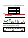
Current measurement by only two CTs
The 3-phase system must be balanced; therefore I3= – I1 –I2 and only two identical CTs are required:
Chapter: Installation
Other systems of voltage
I1 CT
Gen I1
GENSYS
I2 CT
Gen I2
Current inputs
Gen I3
Power –
Gen common
This is used in middle-high voltage applications. The I3 value is less accurate.
23
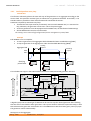
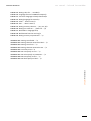
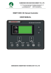
2.2.4
Connection diagram
+
A56 Z0 9 0026
8-35VDC
Power +
Power –
–
Pickup
F
Speed out
Speed common
Isolation
J1939
AVR common
GENSYS
Starter No1
G
ECU
Analog
AVR
F
L1
Gen L1
L2
0
Gen L2
Output 1
COMPACT
Output 2
L3
Gen L3
N
Gen N
Examples:
- +/- pulses to speed gov.
- Visual/audio alarm
- Generator breaker trip
- Lubrication pump
- Reverse power
- Excitation command
Speed
governor
AVR out
Shield
Fuel
Analog
PRIME
Output 3
Gen I1
Gen I2
Output 4
Power –
Gen I3
Gen common
Output 5
NO Relay output 1
aux.
Relay Common 1
Output 6
NO Relay output 2
Relay Common 2
Load
Common
Earth fault
Earth common
Analog input 1
Analog input 2
Bus L1
Bus L2
Analog input 3
GND
CAN2:
J1939/Extensions
Bus L3
Bus N
CAN L
GND
CAN H
CAN L
RES
4 mm², AWG 11
Setup
Supervision
Modbus TCP
Firmware update
CAN H
RES
CAN1:
Inter-GENSYS
F
Isolation
Digital inputs
1 ... 9
Examples:
Gen. breaker aux.
Remote start-stop
Emergency stop
Ext. electrical fault
+/- speed inputs
Low water temp
Low water level
Low fuel level
Low oil pressure
Charger fault
By default, the inputs
1, 2 and 3 are preset
to these functions
The diagram shows that the Potential Transformers can be connected in various ways:
Star (wye) on generator side (1 insulated high-voltage terminal per PT) ; the ratio is for example
√
√
Vee on bus side (2 insulated high-voltage terminals per PT) ; the ratio is for example
user manual - technical documentation
A56 Z0 9 0020 B EN
3
OPERATION
3.1
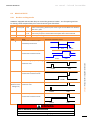
OPERATING MODES
GENSYS can control the generator in three modes. They are activated through buttons:
3.1.1
Mode
Button-Led
Use
Automatic
AUTO
Refer to chapter Applications
Manual
MAN
Refer to chapter Commissioning
Test
TEST
Used only to check the start sequence of the generator taking the load. To
exit this mode, press either AUTO or MAN
Manual mode
1. Press MAN: this lights the associated LED
2. Press START: GENSYS starts the engine (this is detailed further)
3. Press the generator O/I button to switch the generator ON the load. Depending on the setup,
the process can include:
synchronization (if bus bar is live)
closing of the generator breaker
loading of ramp (if bus bar is live)
GENSYS manages the load according to the setup.
4. Press the generator O/I button to switch the generator OFF the load; this may imply
unloading the ramp (paralleling) and opening the generator breaker; the engine runs on
5. Press STOP
One time to cool the engine down and stop it when the time is up
Two times to stop the engine right away
Synch
r
Close onize
b
Load reaker
O
Start
I
START
Generator
is ready
Waiting
Wait
&
Stop
On-load
O
I
STOP
op
St
r
ad
Unlo breake
n
e
p
O
STOP
STOP
STOP
r
eake
n br top
e
p
O
S
t&
Wai
Pressing STOP when the generator breaker is CLOSED starts the standard unload sequence, opens
the breaker and stops the engine after cool down.
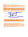
3.1.2
Automatic mode
The automatic mode is subjected to a digital input assigned to the function Remote start (of
generator start sequence).
Until the digital input is activated (and any delay expired), the Auto mode does not prevail. To set
delays, refer to the chapter 8.3.1, p.105. If the input is de-activated, GENSYS is considered as
unavailable.
3.1.3
External requests
You can substitute the front panel buttons for external buttons/PLC commands connected to a pair
of digital inputs.
The external requests control the Led in the same manner as the local buttons. The last request (external or
front panel) override the others.
MAN/AUTO
If both signals contradict each other, the Manual mode request overrides the Auto mode request.
START/STOP and Increase/Decrease
Regardless of the mode, you can start/stop the engine or increase/decrease the speed/voltage:
Local buttons
Substitute function
START / STOP
Manual start/stop request
Shift + /
Increase/decrease speed in man. OR Increase/decrease voltage in man.
user manual - technical documentation
A56 Z0 9 0020 B EN
3.2
START SEQUENCE
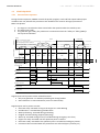
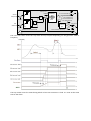
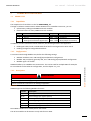
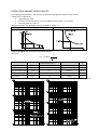
3.2.1
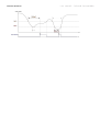
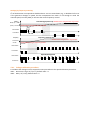
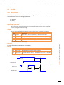
Internal Start sequence
During the start sequence, GENSYS controls the prelub, preglow, crank and fuel outputs when proper
conditions are met, whereas the protections are inhibited. This concerns all engine protections.
Main start phases:
1. The engine is considered to have started when the speed reaches the crank drop out
2. The engine gets ready
3. The generator gets ready; the protections are activated unless the "Safety on" delay [4852] is
set to protract inhibition
Thresholds
SPEED
Speed 1 or Speed 2 (set points)
START
Idle speed (3468); by default: 1300 rpm
Crank1 drop out (3462); by default: 1300 rpm
1st Start
attempt
POST-START
2nd Start
attempt
No-protection
time
Time-outs/delays
Start request
Default
values:
10s
Prelub
3455
Preglow
3456
10s
10s
10s
10s
10s
Stop request
10s
Crank
3457
Crank rest
3458
Preglow
3456
Crank Warm up Stabilisation (speed+volt) Safety on
3457
3467
2004
3469
Start
Waiting
Preglow
Start Warm-up
10s
30s
Cooling
3470
Rest
3472
Engine state (4001)
Waiting Pre-start
Preglow
Nominal
speed
Engine
ready
Digital outputs (if preset):
Air conditioning
Generator ready
Cool
down
Normal running
Starter No. 1
Fuel
Warm up
Excitation command
Generator ready
Protection valid
Digital inputs can be preset to Start-related functions:
Only start generator: run without paralleling nor closing breaker
Start inhibition: no start whatsoever (even in manual mode)
Digital outputs can be preset to states:
Generator stop: activated as long as the engine is in state Waiting
Prelubrication : activated during prelubrication
Water preheating : activated during preheating
Preglow: activated during preglow (spark plug)
Warm-up: activated during warm-up. Inhibited during emergency start if any
Engine not ready: activated until the speed set point is reached
Generator ready: activated as the speed set point is reached and voltage is present
Protection valid: activated when the protections are enforced (expiry of Safety on)
Stop
Idle Waiting
Note: Make sure the speed threshold [3468] is below or equal to [3462].
Setting Label
Description
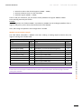
3453 Fail to start engine t-o Maximum time allocated to start. Default value: 10.0s
Status Label
Fail to start engine
Description
Activated if engine has not started until 3453 has expired or 3461 has been passed
user manual - technical documentation
A56 Z0 9 0020 B EN
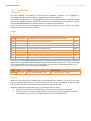
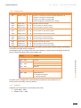
Conditions before start-up
GENSYS monitors the oil pressure and water temperature:
1. Prelubrication check: the oil pressure must be ABOVE the threshold [3473]
2. Preglow check: the water temperature must be ABOVE the threshold [3474]
Setting Label
Description
Note
3473
Oil prelubrication Oil pressure low threshold
3474
Water temp.
Default value
0mbar
Water temp. low threshold Digital input Preheating required in auto mode 0°C
If you give them the thresholds the value 0, the readings from the analog sensors are not checked
before start-up.
When both values are OK, the output Air conditioning is activated (provided an output is preset accordingly).
When 3454 expires, if either reading is below its threshold or the speed is below the set point, the fault
"ENGINE not ready" appears.
Setting Label
3454
Description
Associated clock in Scada
Max prelub t-o Max. time allocated to engine to prestart. Default value: 10.0s Prelub timer 4453
Status Label
Not ready
Description
Associated digital output
Activated if no pre-start until 3454 has expired
Engine not ready
Oil pressure
Prelubrication
[3473]
0
[3455]
[3454]
t (4453)
Fail to start
Success: prelubrication can be resumed later manually or on external fault (see next time chart).
Failure: the starting sequence stops.
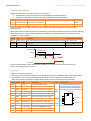
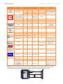
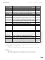
Protections
GENSYS can activate protections:
below the oil low threshold or above the water high threshold, the "ENGINE not OK" information shows
the attribute CT of the threshold determines the protection type (8 values; see Protections) to
which the signaling contributes; A digital output can be configure according to this protection.
Setting Related Label
2362
2380
2365
2383
Description
–
LV min oil
Oil pressure low threshold
2363
TM min oil
Oil pressure min timer
2364
CT min oil
Action on oil pressure min passed
–
LV2 min oil
Oil pressure very low threshold
2381
TM2 min oil
Oil pressure min timer
2382
CT2 min oil
Action on oil pressure min passed
Validity Function block
The output shows the status with
respect to the two thresholds; it is
incremented/decremented when a
After threshold has been trespassed for its
delay TM:
stabilis.
IN
LV
–
LV max wat. t° Water temper. high threshold
2366
TM max wat. t° Water temperature max timer
2367
CT max wat. t° Action on water temp max passed Always
–
LV2 max wat. t° Water temp. very high threshold
2384
TM2 max wat t° Water temperature max timer
2385
CT2 max wat. t° Action on water temp max passed
TM
Reset
CT
any state
H, HH
L, LL
3
C1
OUT: past thresholds
Clock
TON
1
8
CT: 8 potential effects.
OUT: protection type
Manual mode
In manual mode, the start request is manual, the stop is automatic (protection) / manual (request).
If a digital input and a digital output are associated to one function (refer to the chapters 8.3.1 p.105
and 8.3.2, p.107), they are interconnected.
Function
Prelubrication
Preheat
Parameter
oil pressure
water temperature
Sensor
not required
not required
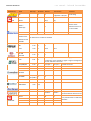
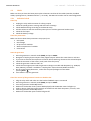
Summary
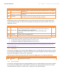
A J1939 value has priority over an analog input. To dismiss a J1939 analog value, set the related switch
to the desire analog input.
GENSYS does not take into account an oil pressure fault during the start sequence.
Note: Preheating (with validity = Always) is used in Auto mode, Manual preheat request in manual mode.
In next illustrations, the typical set-up is through the switch 3450/3451.
Alternately, GENSYS receives the fault signal through a digital input whose validity is configured for a
given engine state (refer to 8.3.1); then, to by-pass the internal processing, set the GENSYS threshold to 0.
J1939
Analog
input
number
CAN interface
3
2
1
2
1
J1939 Low oil pressure alarm*
Oil pressure
3
J1939 Low oil pressure fault*
0
Prelubrication*
3473
2362
2380
3450
Protective effect
(CT, see Protections)
Validity
Oil pressure fault
Never
Always
Post starting
Stabilized
Manual prelub request*
J1939
Analog
input
number
Man. Oil pressure
CAN interface
3
2
1
2
1
0
Never
Always
Post starting
Stabilized
Never
Always
Post starting
Stabilized
Regulated preheating permission*
Preheating request*
3
Validity
Water
temperature
L 3474
H 2365
3451
Water
temperature
J1939 High water temperature alarm*
J1939 High water temperature fault*
Water preheating*
Protective effect (CT,
see Protections)
>1
H 3475
Coolant temp. fault*
Never
Always
Post starting
Stabilized
* Assignment of a direct or remote digital input or output in CRE Config
Usual validities are shown. They are preset in CRE Config at the same time as the function. Refer to 8.3.1, p.105.
Cooling fan is also actuated in manual mode if the engine runs.
Cooling fan*
user manual - technical documentation
A56 Z0 9 0020 B EN
Setting Label
Description
3473 Oil pressure threshold
Lubrication pump run below this low pressure threshold. Set to 0 to bypass
prelubrication.
3474 Preheat coolant
Preheating pump run below this low temperature threshold. Set to 0 to bypass
temperature threshold preheating.
Air fan is activated when water temperature is over this threshold (default
3475 LV cooling
value: 40°C). Air fan is not active when engine is stopped
Crank
With multiple starters, preset digital outputs to Crank2 and Crank3. The Starter number depends on
the preset output number. The starters are attempted according to the starter numbers as far as the
engine fails to start.
Setting Label
Description
By default
0
3459
Starter alternance type:
0: one attempt per starter per round (the starters take the token after one
Starter order another). In CRE Config, select “Alternative”
1: each starter makes several attempts in a row. In CRE Config, select
“Consecutive”
3460
1st starter
1
Number of the first energized starter
3461 Start Attempts Maximum count of start attempts allowed by starter. Value: 0…15
3
Examples with 3 starters, with 1st starter set to 2 and number of start attempts configure to 3:
In alternative mode, the sequence will be.2-3-1-2-3-1-2-3-1
In consecutive mode, the sequence will be 2-2-2-3-3-3-1-1-1
Note: For each starter's functions (starters 1 to 3), in “Configuration/Engine/Start settings” there
are separate lower thresholds under which the starter drops out. The values depend on starter type
(electric, pneumatic...).
3.2.2
Idle speed
To prevent a cold engine to run at full speed, GENSYS can run it at idle speed for a short time on startup.
For this purpose, GENSYS feeds a “warm up” command to an external speed controller with idle speed
input when the engine is in states “Start”, “Warm up”.
The idle speed is fixed by the speed controller. Parameter 3486 allows to command a speed ramp.
Setting Label
Description
3468
Speed set point in pre-start.
3.2.3
Idle speed
Smoke limiting
To prevent a cold engine from over-emitting, GENSYS can run it at idle speed for a short time on startup.
For this purpose, GENSYS feeds a smoke limiter command to an external speed controller with smoke
limit input when the engine is in states “Start”, “Warm up” and “Nominal speed”.
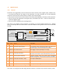
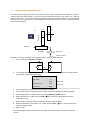
3.2.4
External auto start module
Some engines are equipped with an Automatic Start Module (ASM). On start (automatic/test/manuel
mode), GENSYS empowers it to energize the crank and fuel and to synthesize the engine
alarms/faults.
The setup depends on the type of ASM:
COMMON
Step
Presetting
Connections to ASM
0
To inhibit GENSYS internal start sequence, activate
“External start sequence” in “Configuration/Engine”
1
In CRE Config/Configuration/Outputs/Digital outputs,
preset a digital output to Start request
Connect it to a start request input (it replaces
the GENSYS fuel output)
2
In CRE Config/Configuration/Inputs/Digital
preset a digital input to Remote alarm
Connect it to an engine alarm output
3
In CRE Config/Configuration/Inputs/Digital inputs,
preset a digital input to “Remote hard shutdown”
(immediate engine stop) or “Remote soft shutdown”
(stop after cool-down sequence). See further
inputs,
Connect it to an engine fault output
As with a GENSYS-controlled start, the engine start time-out [3454] applies.
ASM with a “Generator ready” digital output
Step
4
Presetting
Connections to ASM
In CRE Config/Configuration/Inputs/Digital
preset a digital input to “Generator ready”
inputs,
0: Remote start
1: Start request
Auto Start
Module
Engine ready
Start sequence
Engine protections
Remote alarm
Remote hard/soft shutd.
Electrical control and
protections
Oil pressure
Water temperature
Magnetic pick-up
Engine
GENSYS
Generator ready
Engine alarm
Engine fault
Crank,
Fuel
Connect it to an engine ready output
AVR
Governor
x
I
U
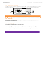
When ASM validates the speed, it sends the signal of readiness, and GENSYS regains the control:
Generator
ready
Stabilization [3469] + Safety on [E4852]
Normal running
Start
request
Stop request
Waiting
ASM without a “Generator ready” digital output
No extra presetting. In absence of Engine fault, at expiry of stabilization timeout [3469], GENSYS
declares the generator readiness if the speed and voltage are valid.
user manual - technical documentation
A56 Z0 9 0020 B EN
3.2.5
Power delivery
The sequence depends on the paralleling type (refer to the chapter Applications):
Dynamic paralleling: the excitation, generated with the crank output, is activated in the
states Start, warm up, and nominal speed
Static engine paralleling: the excitation, sent apart, is activated in the states Engine ready,
generator ready
The succeeding states of the generator can be followed locally, in the Information page (variables
4000 and 4001).
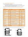
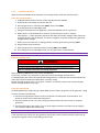
3.2.6
Stop and faults
On manual request (local or remote), GENSYS executes a sequence to open the breaker and cool the
engine down (soft shutdown); the succeeding states can be followed in the Information page.
In event of a major fault, GENSYS immediately (hard shutdown) opens the breaker and stops the fuel.
Any other internal protection can trigger either process through assignment of an action, provided an
output is preset, is connected and feeds back the related remote shutdown input; for more details,
refer to the section Protections.
The various potential external events show on the following diagram:
Manual stop request*
Fuel
Soft
shutdown
sequence
Remote start/stop
Remote soft shutdown*
Breaker command
>1
Remote hard shutdown*
Emergency stop
Hard
Breaker fault
Sensor lost
Fail to stop
shutdown
Speed > 0
Engine fault
&
Energize to stop*
U=0
Damper*
* Assignment of a direct or remote digital input or output in CRE Config
If the relay has to be energized to stop the generator, use the output “Energize to stop”. GENSYS stops
the air feeding (Damper output) if the proper digital output is connected and preset to Damper function.
3.3
PROTECTIONS
3.3.1
General
Protections are triggered by internal and external events (alarms, faults, digital inputs, CAN bus loss,
…). To protect the process, the engine or the alternator, you must associate one of the predefined
actions to each such event. These actions or effects are of various kinds:
they can just raise an alarm; notice shows on the front panel (ANSI30); a summary can be reported
they can secure the equipment: the engine stops, the breaker trips safe … and can activate a free
protective digital output
they can invoke a fallback plan (reconfiguration).
The action is an attribute of the protection: CT settings, or of inter-module CAN bus loss : fallback
setting. The Droop effect and value 10 are reserved to CAN bus fault (prefer 8 or 9 to have some load
sharing).
Triggering events
Fail synch.
CAN bus fault
Battery undervolt.
Water temp. excess
Oil press. default
...
Reporting
Common effects
ALARMS
Alarm
Targeted
protection
type
Alarm summary
Annunciator
Bus electrical fault
Gen. electrical fault
Soft shutdown summary
Fault (Soft shutdown)
Security (Hard shutdown)
Fault (Soft shutdown) + Help
Gen. electrical fault + Help
Droop + Alarm / (Droop +) No start if Static paralleling
Min/Max Analog n
Value
Kind
Action
Description
0
–
Disable (no action)
–
1
Fallback
Generator electrical fault
The protection opens generator breaker and tries to resynchronize again. Count of attempts set by 4854
2
Fallback
Bus electrical fault
Usual trigger: frequency/voltage out of range
3
Alarm
Alarm
Notice as alarm on front panel
4
Security
Fault (Soft shutdown)
Generator breaker opens allowing the engine to cool down
off load for the duration of the cool down timer, then stop
5
Security
Security (Hard shutdown)
Generator breaker opens and engine stops immediately
without cooling down; “Serious fault” shows as information
6
Fallback
Fault (Soft shutdown) + Help
See chapter Fallback plans
7
Fallback
Gen. electrical fault + Help
ibidem
8
Fallback
Droop + Alarm
ibidem
Droop + No start if Static paralleling If already started, the generator runs on; otherwise, no
start
ibidem
10 Degraded No start if Static paralleling
9
Fallback
The actions are configured in CRE Config. Numerical values 0…10 show only in text file. See 8.2, p.102.
user manual - technical documentation
A56 Z0 9 0020 B EN
3.3.2 Audio or visual annunciator
To trigger an external annunciator whenever a protection trips, connect it to an output preset to the Horn
function; the signal duration is modified by 2478; alternately, an input can be used for remote reset:
RS
Protection
2478
S
OUT
t
Horn
R
Stop horn
Setting Label
2478
Description
Horn delay Duration of ring. Default value: 10s. 0 means the horn will buzz until being manually stopped
3.3.3 Call for help
A help protection calls another engine for help and contributes to a summary (Soft shutdown or GE
electrical fault). See Fallback plans.
3.3.4
Emergency stop
The emergency stop function can be done in two ways:
Connecting a normally closed “mushroom-type” button to the digital input “Emergency
stop”. This is a pure software solution.
Hard-wired solution, where the button also disconnects power supply from the controller
outputs like Fuel and Crank.
Note: In case of many cranks, don’t forget to disconnect all cranks
3.4
POTENTIAL ALARMS/FAULTS CATALOG
The potential alarms/faults are listed below.
Potential Alarm/Fault: Alarm/Fault label; this text shows in the Alarm/fault pages
Action on alarm/on fault: this variable allows you to define the associated protection type (8
potential values; target to which the signal contributes)
This list can be downloaded from CRE Config/System/PC transmit-receive/Action on alarm/fault”.
ELECTRICAL (all trip after a definite time, except Short circuit which trips after an IDMT; see
Appendix):
Potential Alarms/Faults
ANSI
Description
On alarm
On fault
Overfrequency
81H
Generator is in over frequency
2402
2438
Underfrequency
81L
Generator is in under frequency
2405
2441
Undervoltage
27
Generator is in under voltage
2411
2447
Overvoltage
59
Generator is in over voltage
2408
2444
Min kVAR
37Q
Generator reached a minimum of kVAR
2423
2459
Max kVAR
32Q
Generator reached a maximum of kVAR
2426
2462
-kW
32RP
Generator is in reverse kW
2420
2456
-kVAR
32RQ
Generator is in reverse kVAR
2429
2465
Min kW
37P
Generator reached a minimum of kW
2414
2450
Max kW
32P
Generator reached a maximum of kW
2417
2453
Generator is in over current
2432 (I>)
2468 (I>>)
2435 (I0>)
2471 (I0>>)
–
2477
2352
2370
2805
–
–
Hard
shutdown
Alarm
–
Max I
50
Max In
50N
Generator is in over neutral current
Short circuit
51
Short circuit between generator phases
Over speed
12
Engine is in over speed
Generator voltage measurement is
–
inconsistent with configuration [2003]
Includes A fault is triggered if the breaker does’nt
50BF send proper feedback
An alarm is triggered if the generator
breaker controls do not work correctly
Phase measure
Breaker fault*
Breaker alarm*
Fail to synch
25
The unit cannot synchronize to Bus
2804
Uneven kW
90P
See 4.4.1, p.45
3710
–
Uneven kVAR
90Q
ibidem
3713
–
* According to the state of the module, a breaker alarm or fault could appear. It could be a fail to close breaker, fail to open breaker
or breaker open suddenly.
Summary with threshold codes (as they show in text file), output and action codes on alarm & fault:
kW
Setpoint
Setpoint 2
Nominal
I, U
Reset
2415
2451
2418
2454
2412
2448
H
HH
L
LL
L
LL
2852
2851
H
L
2854
2857/60
3708
2109
2110
kVAR
Gen active power flow
H
L
H
32P
2417
2453
32RP
2420
2456
37P
2414
2450
Ramp
Load sharing
Uneven kW (3710)
Constant
Set point
Setpoint
Setpoint 2
Nominal
I, U
Reset
2424
2460
H
HH
32Q
2426
2462
2427
2463
H
HH
32RQ
2429
2465
2421
2457
L
LL
37Q
2423
2459
3711
H
Load sharing
Uneven kVAR
(3713)
user manual - technical documentation
A56 Z0 9 0020 B EN
Load shedding (Refer to 0, p.54):
Potential Alarms/Faults
Description
Trip alarm
On alarm
Generator is in under frequency in percent
3702
Generator reached a maximum of kW in percent
3705
All trip out
2862
Others:
Potential Alarms/Faults Description
Min oil pressure
Max
temperature
Sensor lost
Oil pressure under minimum
water Max water temperature over maximum
Fail to stop
Not ready
(1)
On level 1/Min On level 2/Max
2364
2382
2367
2385
Triggered if the speed is 0 and engine has started
Hard shutdown
Triggered when engine does not stop correctly
Hard shutdown
See the section 3.2.1, p. 27
Fail to start
ibidem
Min battery voltage
To set the thresholds, refer to E, p.76
2358
2376
Max battery voltage
idem
2361
2379
CAN1 bus fault
Communication problem on the inter-unit CAN
3052
–
CAN2 bus fault
A J1939/CANopen bus error is detected. See 7.3, p.94
3053
–
Overspeed
(Extreme) Over-speed detected by J1939
3104
3105
Low Oil P
(Very) Low oil pressure detected by J1939
3108
3109
High Cool T
(Very) High water temperature detected by J1939
3106
3107
Malfunct lamp
See 7.3, p.94
3110
Protect lamp
ibidem
3111
Amber lamp
ibidem
3112
Red lamp
ibidem
3113
(1) For an external start module, the alarm/fault [4473] Engine not ready corresponds to a loss of generator ready signal.
3.4.1
Synthesis
The faults and alarms are synthesized as follows. The specified action selection is depicted as a
selector in the middle of the illustration. External relays can contribute to Generator protection.
Fault inhibition
Overspeed
Overcurrent
Fail to stop
Speed sensor lost
TOFF
+
Breaker fault
Remote hard shutdown
Auto-start
module or
Ext. relay
+
Forced run
Hard Shutdown summary
+
+
POWER/ENGINE
Serious fault
Remote soft shutdown + help
PLC
Security
Fault
Remote soft shutdown
Gen. electrical fault
+
Remote fault+ help
Bus electrical fault
Alarm
Auto-start
module or
Ext. relay
Protections
+
+
Forced Soft Shutdown summary
run
+
+
Fault summary
Gen. Electrical Fault summary
PLC
Generator fault request
Bus Electrical Fault summary
Excitation fault
+
Generator
Remote alarm
Auto-start
module or
Ext. relay
Call for maintenance
J1939 alarms
(overspeed, oil, water)
Min/Max analog
x3
Alarm summary
+
+
ENGINE Fault
Fault inhibition (battle switch): refer to the Appendix/Standards for generators/NF E37 312.
Print & fill the table at the end of this manual; it will help determine the potential causes of a signal.
Clearing of faults/alarms:
- Locally: Shift +
- Remotely: use the “Fault reset” input function
Protections
RS
S
OUT
Fault reset
R
J1939/DM3
E
C
U
user manual - technical documentation
A56 Z0 9 0020 B EN
3.5
BREAKER MANAGEMENT
With the breaker feedback, failures and unexpected opening (ANSI94, ext. or manual) are signaled.
A time-out [2304] (5.0s by def.) precedes the signaling that the breaker has not opened/closed:
Generator fault request
Relay 1
Internal protections
Tripping
Relay 2
Remote shutdown
Order to open the breaker
S
2304
t
Generator breaker feedback
&
>1
t
Closing
Order to close the breaker
3.6
Fail to close/open the breaker
R
1
2304
Breaker fault
RS
&
R
RS
Generator breaker open suddenly
1
S
&
Generator active power flow
CYCLES BEFORE MAINTENANCE
You can program maintenance operations based on counts of cumulated running hours or days. Five
cycles are based on running hours, five cycles are based on running days. The counters of the latter
cycles are incremented every day whether the generator has run or not. In the frame of a
maintenance program, they are used to call for various maintenance operations: the longer the
running cycle, the deeper the generator inspection. The cycles usually imbricate in one another.
In CRE Config/Configuration/Maintenance or in the text file, set the cycle name and the duration:
Setting
Label by default
Description
3500 … 3509
Cycle x(h/d) or Meter x(h/d)
Cycle duration in running hours (h) or days (d); x=1 …5
The alarm name shown when the cycle is elapsed will be the label. The countdown of left hours/days
since the latest reset can be read in CRE Config/Scada/Maintenance cycle monitoring or in
“Display/Maintenance” (“off” means that the cycle is not defined). It is saved into non volatile memory.
Reading
Label
Description
.0850 … 0859
Maintenance (hours/days) n°x
Countdown in running hours (h) or days (d); x=1 …5
At any time, you can reset a counter in CRE Config/Config./Maintenance: press counter Reset button.
When a cycle duration has expired, the corresponding alarm is raised. Read the alarm page to know
which cycle has run out and reset the alarm. This resets also the counter of the corresponding cycle.
3.7
3.7.1
FILLINGS OF FLUIDS
Presetting
GENSYS can monitor the levels of fuel, oil or coolant while the generator is running. Each fluid monitoring
requires either an analog resistive level sensor or two switches (one high level and one low level):
Using CRE Config/Configuration, preset as follows (say xxxx = fuel, oil or coolant).
Sensor 0…500 + settings:
In “Filling”, preset an analog channel to a sensor input and set thresholds
In “Inputs/Analog inputs”, calibrate the corresponding sensor
Switches: in “Inputs/Digital inputs”, preset 2 channels to xxxx low/high level.
Analog
input
number
3
2
1
2
1
3
xxxx filling
0
xxxx filling
xxxx low level
3450
xxxx high level
Manual xxxx fill request
3.7.2
Filling up
In CRE Config/Outputs/Digital outputs, preset an output to the function xxxx Filling up (filling order).
Automatic mode
GENSYS autofills the tank when the low level is reached:
xxxx level
High level
Low level
t
Manual mode
In “Digital inputs”, preset an input to the function Manual xxxx filling up request.
It is interconnected with the digital output preset to xxxx filling. After pressing MAN, press the
external push-button till the desired level is reached (the upper threshold is not enforced).
user manual - technical documentation
A56 Z0 9 0020 B EN
4
APPLICATIONS
In island operation, each generator in the aggregate is controlled by a private GENSYS unit. All GENSYS
units are CAN-connected. A typical configuration for paralleling is the following:
Starting from the default settings, just enter the installation:
Setting
Label
Value
2000
Count of gen.
1 ≤ N ≤ 32
2001
GE Number
1 to 32 (differs for each GENSYS on one bus)
The default settings are in bold:
Setting
Label
Value
2050
Paralleling mode Dynamic [0], Static [1]
2002
DeadBus manag. No[0], Yes [1]
2850
Load/Unl. mode
No [0]. To change it, see section 4.4.3, p.49
4.1
FIRST START
All the GENSYS units with an activated “Remote start” input start in AUTO mode. The fastest
generator’s GENSYS makes sure that the bus bar is unpowered (dead bus bar), closes its breaker and
takes the load.
The others synchronize with the bus bar.
Then, if [2850] = 0, all the generators remains on duty.
If [2850] = 1, 2 or 3, depending on the load demand, the aggregate decides which generators must
stop. Messages are interchanged over the inter GENSYS CAN bus.
Calling a generator for production requires
1. An election based on load demand (see 4.4.3, p.49)
2. The synchronization of the elected generator
3. A load ramp for soft transfer
4. A load sharing (kW/kVAR) according to the percent of load of each generator
4.2
SYNCHRONIZATION
4.2.1
Configuration
Various settings and readings are offered to control and follow the synchronization:
Setting
Label
Description
Default
2800
Voltage match
Max. difference (in % of nominal value) between generator & bus
bar voltage for coupling
5%
2801
Freq. match
Max. frequency difference between generator and bus bar for
coupling
0.1Hz
2802
Phase match
Max. phase angle difference between generator and bus bar for
coupling
10°
TM Fail sync
Allocated time to synchronize
200s
C2S dwell time
Synchronization dwell time before authorizing to close the breaker
0.2s
2803
2809
(1)
Reading Label
Description
0306
Phase sequence
Phase sequence approve to close breaker
0307
Voltage
Voltage gap approve to close breaker
0308
Frequency
Frequency gap approve to close breaker
0309
Phase
Phase gap approve to close breaker
0310
C2S check OK
Synchroscope result
(1) This parameter can be modified using TXT file or modification by variable number menu.
GENSYS launches the synchronization only if the bus bar features at least 80% of nominal voltage.
The bus bar frequency and voltage are the set points of loop controls. When the generator and bus
bar match, GENSYS orders the breaker closing.
Time chart:
Allocated time to synchronize
[2803]
C2S check
[0310]
Synchronization done
Generator
breaker
position
C2S dwell time
[2809]
If synchronization fails: GENSYS stops the generator. Another GENSYS is elected if Load/Unl. mode is
1,2 or 3; the ensuing action can be configured as described in 3.3, p.34:
Protection
Label
Values as action
Synchronization failure CT Fail synch Alarm [3] (by default), Soft shutdown [4], Hard shutdown [5] etc
user manual - technical documentation
A56 Z0 9 0020 B EN
4.2.2
Tuning
Prerequisite: the outputs Speed & AVR are scaled to match the generator. See5.2, p.60 and 5.3, p.62.
Settings are settable in “Configuration/ Synchronization”.
Setting
Label
Voltage
Description
Default
2951
P
Proportional
50
2952
I
Integral
20
Proportional
Integral
5
20
Proportional
70
Frequency
2901
2902
P
I
Phase - Angle
2905
P
Tuning process:
1. A generator has already started and its breaker is closed
2. Unplug the new generator’s breaker connector
3. Start this generator and go to “Display/Synchronization”
4. The generator synchronizes within 5s; otherwise, isolate the root cause (Voltage, frequency
or phase) and adjust:
In a first time, the proportional in order to be closer of the set point
In a second time (if need), the integral in order to faster reach the set point
4.3
LOADING AND UNLOADING RAMP
4.3.1
Configuration
After a synchronization, GENSYS ramps up the generator load (soft transfer) to avoid overload or an
abrupt load kick (hard transfer):
1. GENSYS calculates the average active and reactive powers from the information conveyed by
the Inter-GENSYS CAN bus
2. It starts a load ramp to reach progressively these values (kW and kVAR regulations).
In the same way, when GENSYS must stop, an unload ramp is done.
Various settings are used in ramping up/down:
Setting Label
Default
Description
Example
2851
Gen low lim
10kW
Wattage lower limit
50kW
2853
Loading ramp time 10.0s
Time to ramp up power from 0 to nominal power
50s (slope: 10kW/s)
2856
Unloading
time
Time to ramp down power from nominal power to 0 22s (slope: 23kW/s)
ramp 10.0s
Example: Nominal power = 500kW
Load (kW)
300
Active power set point
250
200
150
100
Low limit
50
Time to ramp up
t
Time to ramp down
0
1 3 5 7 9 11 13 15 17 19 21 23 25 27 29 31 33 35 37 39 41 43 45 47 49 51 53 55 57 59 61
Before isolating and stopping a generator, its GENSYS unit decreases its load from the current value
to the low limit, where it opens the breaker, and the load drops to 0.
If a breaker fails to open at the end of an unload ramp, the generator continues to share the load as
described further. GENSYS raises a breaker fault.
4.3.2
Tuning
Prerequisite: the outputs Speed out and AVR out are scaled to match the generator. See 0, p.60 and
5.3, p.62.
If the generator is in reverse power or does not takes enough load, set P in menu “Configuration/
control loop /Ramp kW or kVAR” (0 … 200%).
Note: On LCD screen, you can visualize during the ramp, the kW/kVAR setpoint and the kW/kVAR
measure.
Setting
Label
Description
Default
2913
Ramp kW P
Proportional of kW ramp
100
2967
Ramp kVAR P
Proportional of kVAR ramp
100
user manual - technical documentation
A56 Z0 9 0020 B EN
4.4
POWER MANAGEMENT
4.4.1
Load sharing
GENSYS is informed of the other generators’ loads through the CAN bus; they share the load in
proportion to their power rating. This strategy is more reliable and accurate than an analog solution.
The speed control is used to share the active load. The AVR control is used to share the reactive load.
Various readings are available:
Label
Description
kW GEx
Percent of nominal active power supplied by each generator (variables 400 to 431)
kVAR GEx
Percent of nominal reactive power supplied by each generator (variables 465 to 496)
Nom kW GEx
Nominal active power supplied by each generator (variables 433 to 464)
Nom kVAR GEx Nominal reactive power supplied by each generator (variables 498 to 529)
The shares taken by the generators are monitored on CRE Config or LCD screen.
The relative deviation is (Generator share – Average load) / Average load. When it exceeds a
threshold for a given time, a fault is raised if set.
Setting
Label
Description
3708
Uneven kW lvl
Threshold (in %) for the generator active power
3709
Unev. kW delay
Delay before raising fault
3711
Unev. kVAR lvl
Threshold (in %) for the generator reactive power
3712
Unev. kVAR dly
Delay before raising fault
Generator share
kW/kVAR
Average power
lvl
%
Deviation
dly
Uneven signal
t
The statuses and actions on alarm are as follows (the potential actions are listed in the chapter
Operation/Protections):
Status
Label
On alarm
Description
4263
Uneven kW
3710
Generator active power is far from the average of all active powers
4264
Uneven kVAR
3713
Generator reactive power is far from the average of all reactive powers
If a GENSYS unit does not send any more frames on the inter-GENSYS CAN bus, all the generators are
forced to start and take a load in a natural manner.
To withdraw GENSYS units from CAN bus communication, use either method:
set the digital input Inhibit GEn *4557 … 4588] to 1
change the variable *4557 … 4588+ via Modbus TCP
To disconnect a GENSYS unit from the inter-GENSYS CAN bus, you must change the count of generators
on all the other GENSYS units.
TUNING
Prerequisites:
The outputs Speed out & AVR out are scaled to match the generator (0, p.60 & 5.3, p.62).
At least two generators are synchronized.
Factor
kW sharing
kVAR sharing
Setting Label
Default
P
2917
Load sharing P
20
I
2918
Load sharing I
1
P
2959
Share Q P
20
I
2960
Share Q I
1
Once the setting of synchronization and ramp has been done, you can adjust the load sharing. kW
and kVAR share stays within 2% of that power plant average.
Note : The kW/kVAR power plant average in % as well as the kW/kVAR of the genset in % can be
visualized on the LCD screen during the configuration of the PID
You can change :
Proportionnal : to decrease the correction time le temps de correction
Integral : to decrease load sharing difference
Note : Integral is used only if the frequency/voltage centering is set (see 4.4.4 ).
4.4.2
Fallback plans
On events such as fault, CAN bus loss, forced substitution, each GENSYS can invoke a plan to recover or
downgrade the load sharing. Generally one plan is adopted across the aggregate (setting 3052). These
plans are a subset of the actions that can be enforced when a protection trips (refer to 3.3, p.34):
Protection
1
Plan
Description
Generator electrical fault
The protection opens generator breaker and tries to re-synchronize
Fault (Soft shutdown)+ Help
GENSYS calls another generator on duty via the CAN bus
GENSYS waits till the backup is connected to the bus bar
GENSYS opens its generator breaker, lets the engine cool down off
load for the duration of the cool down timer, then stops the engine
7
Generator elec. fault + Help
GENSYS calls another generator on duty via the CAN bus
GENSYS waits till the backup is connected to the bus bar
GENSYS opens the breaker and tries again to synchronize. See
previous section
8
Droop + Alarm
Only available for [3052] i.e. in event of CAN bus loss
9
Droop + No start if Static Idem (CAN inter-GENSYS only)
paralleling
10
No start if Static paralleling
6
Idem (CAN inter-GENSYS only)
In static paralleling (Parall. mode = 1, see 4.5.1), the effect of 9 -10 depends on when CAN bus is lost:
Droop (9) or No load sharing at all (10)
Abortion (9 or 10)
Start
Load sharing
NO generator can start as their AVR never gets the information on when to send the excitation order.
user manual - technical documentation
A56 Z0 9 0020 B EN
Resynchronization after generator electrical fault
A fault detected by GENSYS and associated to Gen. electrical fault can raise such a fault; it can also be
raised from outside (Generator fault request):
Excitation command
Faults inhibition
Resynchro
/ Stop
sequence
Internal trigger
Targeted
protection
type
Gen.electrical fault
&
Excit restart
Engine fault
AVR
Gen electrical fault summary
Generator fault request
In event of a generator electrical fault:
1. GENSYS opens the generator breaker and restarts the alternator excitation (if connected)
during the time [2052]; as long as Excit restart is activated, Engine fault is raised
2. If the fault is still present at expiry of [2051], GENSYS commands a hard shutdown (and
Engine fault is raised again, see 3.2.6, p.33). Otherwise GENSYS attempts to re-synchronize
Setting Label
Default value
Description
2052
Excit. rest
10.0s
Excitation stop time after electric generator fault
2051
TM max. excit
10.0s
Timeout for excitation
2806
Re-sync delay
30.0s
Delay before the GENSYS attempts to re-synchronize with bus bar
2807
Nb re-synch.
3
Maximum count of re-synchronization launches before forced stop
2808
TM reset synch
30.0s
Time to reset the count of re-synchronizations
Example with [2807] = 2:
Generator
electrical fault
Re-sync
delay
Generator
breaker position
Generator status
with respect to
coupling
Paralleled
Isolated
Synched
Paralleled
Isolated
Synched
Paralleled
2
Count of re-synchr.
launches
1
0
Isolated
Stopped
Droop
In event of CAN loss, speed droop and voltage droop are allowed to share kW load and kVAR load
respectively. As droop is allowed, the control does not use any integral.
Frequency droop
The droop is the allowed relative offset:
Speed Droop = (Rated no-load frequency – Base frequency)/ Rated no-load frequency
In the aggregate the generators were requested to run in proportion to their rated power i.e. with
the same P/P0. As they are set with the same droop, they share the same droop characteristic. As the
load demand increases, they respond to the fall in frequency by increasing their active power
outputs simultaneously. The increase in the active power output counteracts the reduction in
frequency. Thus they do not fight one another to control the load (no "hunting").
0%: isochronous
Speed droop=(f0-f)/f0
f0
f
Droop characteristic
1
P/P0
Voltage droop uses voltage in place of frequency
The droops are set in the GENSYS units, not in the ESGs/AVRs:
If 3052 is set to 8 or 9 on all the GENSYS units, all the generators fall back to speed and voltage
droops. It matters that all the GENSYS units be set to the same relative deviations 2204 and 2250.
Setting
Label
Description
2204
Speed droop
% for active load sharing. Default value: 2%
2250
Voltage droop
% for reactive load sharing. Default value: 2%
3052
CAN bus fault
8 or 9
2306
TM base cl br
Delay to close breaker if [3052] = 8 . Default value: 15.0s
If the generators are not yet started, when they lose the CAN bus, a downgraded mode is enforced; the
generator couplings are phased in: the generator #n cannot close its breaker before
[2306]/10 + 7 x n (seconds)
CAUTION
Follow strictly, throughout the aggregate, the scaling procedures (amplitude -offset) of chapter Commissioning
in order to have the best load sharing in droop
Call for help
GENSYS can call for another generator to take over when an internally detected fault targets a
protection of value 6 or 7 (refer to the chapter 3.3, p.34). This can also result from the activation of a
digital input preset to help (forced substitution).
The two offered functions/protection differ by the stop sequence (see protections 6 and 7):
Soft shutdown + Help: GENSYS stops the engine after a cooling down delay
GenElectricalFault + Help: NO cooling down delay
Remote soft shutdown + Help
Call for
help
CAN
interface
Soft shutdown + Help
Internal
trigger
Targeted
protection
type
Stop
sequence
Gen.electrical fault + Help
Remote fault + Help
Call for
help
CAN
interface
user manual - technical documentation
A56 Z0 9 0020 B EN
4.4.3
Load-dependent start/stop
Introduction
This function selectively phases the start and stop of the generators in an aggregate according to the
current load. This prevents overload (you are advised to run generators between 70 and 85%). The
CAN bus makes it possible to share load information & coordinate the actions.
Conditions required by automatic start/stop:
The Remote start input must be permanently active on each GENSYS unit (i.e. connected to
0V); otherwise, the generator cannot start. This is the prime trigger
At least 2 generators must be equipped with a GENSYS unit, all with identical LDSS settings
All the GENSYS units must be in AUTO mode.
The settings are in CRE Config/Configuration/Power management system/LDSS.
Principle
Each GENSYS unit is susceptible:
To start its generator if the aggregate threshold 2854 has been exceeded during [2855]
To stop its generator if the aggregate is under the threshold 2857 during [2858]:
Aggregate load
2855
Loading
request
Unloading
request
2854
2857
2858
t
Running
prime force
H
L
Unload request
Selection
number of gen.
of
TON
TOFF
Load request
generator
2850
[2863]
0 1 2
Unload gen.
if LDSS OK
Stop request
Start request
Start and
synchronisation
Generator number
Remote start
Stop request
CAN (request, # of gen.)
2864
Start request
Plant load
kW
kVAR
EN
H
CAN bus interfaces
Private part
CAN (Load, Unload if LDSS OK)
This includes two stages in the CAN interfaces: decision to load/unload and generator selection:
Production request
A digital input preset to Unload gen if LDSS OK can be used to stop the related generator after checking
that this will not overload the other generators. This input is latched. Unlike the inputs Fault+Help, it does
NOT substitute the generator with another one. The GENSYS must NOT have been given priority by input.
The generator restarts automatically.
Settings across the aggregate:
Setting Label
Possible value Description
2850
Load/Unl. mode
[0] Inhibited
No automatic start/stop of generators according to the aggregate load
[1] GE number Generators start/stop according to the Generator number
[2] Hours run
Generators start/stop according to the GENSYS running hour meter
[3] By custom Generators start/stop according to my priority number *2863+ (1 … 32)
2864
Load dep kVAR
[0] kW
[1] kVAR
Base criterion: kind of power to assess
2854
LV Load thres
Default: 80%
Percent of load on the aggregate above which another generator is
requested to start and share the load
2857
LV Unload
Default: 20%
Percent of load on the aggregate under which a generator is stopped
2855
TM before load
Default: 10.0s Delay with power above threshold 2854 before GENSYS requests
another generator to start and share load
2858
TM before unload Default: 10.0s Delay before deciding to reduce the count of running generators in
load/unload management
Example:
A 4x100kW aggregate with a load that increases linearly from 0 to 400kW, then decreases to 0kW. Start
threshold 2854 is set to 80% & the stop threshold 2857 is set to 20%.
Generator #1 is permanently running. When load increases above the start threshold, generator #2 starts to
supplement generator #1, then generator #3 & generator #4 start. As the load decreases, the generators are
phased out in the order 4, 3, 2.
A56 Z0 9 0020 B EN
user manual - technical documentation
Start-stop by generator number
If this way is selected on all GENSYS units in the power plant, the automatic start/stop phasing is based
on the generator numbers, set in CRE Config/Configuration/Power [2001]:
1. The generator with the smallest number will start first and run onwards forcefully
2. On increasing load demand, the next starts are ruled by the generator number
3. On decreasing load demand, the generators are phased out in the reverse order.
Note: If a generator has been started forcefully in manual mode, it overrides the smallest generator
number. It closes its breaker on the bus bar, even if there is no load (Dead bus management=Yes). The
next generator to start is the one with the next smallest number.
Start-stop by running hours
In this way, the generator to start/stop is auto selected according to the GENSYS running hour meter:
On increasing load demand, the next generator to start is the one with fewest running hours
On decreasing load demand, the next generator to stop is the one with most running hours
Note: If a generator starts and goes past the hours run by a generator which is stopped, the first one
does not immediately stop and the second one immediately starts. Coordination between generators
is activated only on a load/unload request, i.e. in the next start/stop on-load request on the CAN bus.
Start-stop by generator priority number
If this way is selected on all GENSYS units in the power plant, the automatic start/stop phasing is based
on the generator priority numbers, set in CRE Config/Configuration/Power manag system/LDSS [2863]:
1.
The generator with the smallest number will start first and run onwards forcefully
2.
On increasing load demand, the next starts are ruled by the generator priority number
3.
On decreasing load demand, the generators are phased out in the reverse order.
Note: If a generator has been started forcefully in manual mode, it overrides the smallest priority
number. It closes its breaker on the bus bar, even if there is no load (Dead bus management=Yes). The
next generator to start is the one with the next smallest number.
4.4.4
Automatic frequency/voltage centering
Use cases
The secondary regulations (ESG and AVR) might drift, e.g. due to thermal variations.
To counteract these effects, a strategy called frequency centering is applied by default in the aggregate.
The same applies to voltage; the voltage centering can counteract a voltage drift.
When it is used to counteract the droop created by the ESG/AVR, this strategy is called “de-drooping”.
Settings
Settings across the aggregate:
Setting Label
2927 Hz center act
Description
Activation
Default value
1 (enabled)
2926
Hz center gain
Central frequency gain of lead GENSYS
1
2970
U center act
Activation of central voltage
1 (enabled)
Procedure:
1. Adjust the generator speed to get 49Hz by tuning the speed governor offset
2. When the breaker is closed, the frequency must return to 50Hz within 5s
3. Adjust the Hz centering gain [2926] to adjust the time if needed
4. Adjust the generator speed to get 50Hz by tuning the speed governor offset
5. Repeat the steps for all generators
6. Test the load sharing by changing the nominal frequency of one generator to 49Hz.
To do so:
Start a generator at 50Hz and close it breaker
Synchronize the generator at 49Hz
Check that the bus bar frequency comes back to 50Hz and the kW load sharing is
correct
Note : load sharing integral is used only if the frequency/voltage centering is set.
Functioning
Using the CAN bus, the aggregate elects a leader among the generators on bus bar. The centering is
applied only to the leader and requires no extra communications whether digital or analog.
For information, the leader number is indicated in [357] variable.
The centering is a slight proportional correction that slowly brings back the frequency and voltage to
their nominal value. As a result, the leader takes more of the load. Through the load sharing loop of
the other generators, the load balance is regained.
If the default tuning cannot counteract the drift, hone the tuning.
user manual - technical documentation
A56 Z0 9 0020 B EN
4.5
ADDITIONAL CAPABILITIES
4.5.1
Start by static paralleling
Use cases
Starting a full plant with multiple generators in an emergency on dead bus: the generators
are ready to take load in the shortest possible time, without warm-up
Installation with a high voltage transformer: as the generators start, the transformer core is
magnetized progressively, without peaks (no transient short-circuit).
Conditions
On equipment:
The alternators are identical (in particular, same winding pitch)
The AVRs are set for static paralleling: they wait for excitation command on their first start
All breakers must be powered by continuous voltage like 24VDC (so as to close before AC is
available)
On GENSYS:
A digital input is preset to Remote start
A digital output is preset to Excitation command
Digital output to AVRegulator
CAN
CAN interface
Excitation command
Remote start
Dead
bus?
t
0
Y
Emergency
start
Breaker
relay
Static paralleling
Setting Label
Default Description
2050
Paralleling
mode
Dynamic Static (to show the setting in CRE Config, tick Options>Advanced)
2051
TM max excit
10.0s
2053
Excit. speed
90.0% Speed low threshold in % of nominal speed before waiting excitation. Must be
identical in all GENSYS units
2054
Excit. volt.
20.0% Voltage high threshold in % of nominal voltage to validate closing breaker in static
parrallel. It relates to the remanent voltage of the alternators. Must be identical in
all GENSYS units
Timeout for excitation. This parameter must take care of the timer; prelubrication,
preglow, starter, speed stabilization. See sequence further
2056
TM Volt stab.
5.0s
Voltage stabilization timer after excitation order before to pronounce as engine
ready. Must be identical in all GENSYS units. During this stabilization, the unit
working in droop mode.
The generators are synchronized together through the CAN bus:
Speed
400V
[2053]
Waiting
[2054]
Voltage
80V
#3 #4
#5
step
Sequence
1.
2.
3.
4.
5.
Any signaling of bus voltage loss activates the Remote start inputs
All the GENSYS units close their breaker and start their engine
The remanent voltage appears
The fastest generator’s speed reaches *2053]
The slowest generator’s speed reaches *2053] before [2051] expires; then CAN bus orders all
the GENSYS units to simultaneously activate their excitation output; as a result:
the nominal voltage is reached immediately at the same time on all generators
the plant can run at full capacity
Bottom line: full plant availability in less than 10s typically. This meets the NEC700 requirements.
As long as there is a voltage on the bus bar, the dynamic paralleling prevails even if static paralleling
is configured.
user manual - technical documentation
A56 Z0 9 0020 B EN
4.5.2
Load shedding
Introduction
The load shedding is the ability to disconnect less important consumers if the aggregate is
overloaded even when the full capacity is engaged; this prevents a blackout.
Any GENSYS – generally one – in the aggregate can take care of excessive demand. If the kW demand
exceeds the aggregate capacity and/or the frequency has dropped below a threshold for a given
time, the dedicated GENSYS unit activates outputs to shed non-essential loads.
Using two levels of thresholds and delays, you can setup your system to react more or less rapidly
depending on the severity of the situation.
Settings
Setting Label
Description
Default
3702 Under-freq valid.
Enables/disables under-frequency monitoring for load shedding
0
3700 Underfreq thresh1 1st level of under frequency monitoring
96.0%
3701 Underfreq thresh2 2nd level of under frequency monitoring (must be lower than level 1)
90.0%
3705 Max load valid.
Enables/disables overload monitoring for load shedding
0
3703 Max load thresh1
1st level of kW overload monitoring
95.0%
3704 Max load thresh2
2nd level of kW overload monitoring (must be higher than level 1)
100.0%
3706 Threshold1 delay
Delay for 1st level of control (kW and Hz)
6.0s
3707 Threshold2 delay
Delay for 2nd level of control (kW and Hz) (must be shorter than level 1)
2.0s
2861 TM trip out
Min. delay before shedding the next load
5.0s
They are set in CRE Config/Configuration/Power management system/Consumer functions; 2861 thru
Modification. Using CRE Config/Configuration/Outputs, preset up to 5 outputs to xth non-essential trip.
In the same manner as for protections, you can trigger an action when the shedding capacity runs
out (a specific output Trip alarm is signaled if [2862] = 3):
Setting Label
Trigger
Values as action
2862
All non-essential loads are shed
0…7 (refer to chapter 3.3, p.34)
Last trip out
Sequence
When one of the two levels is reached and its associated delay has expired, a trip alarm is set and a
five-tier shedding starts (level 1) or escalates (level 2): at the end of a cycle based on 2861 an extra
non-essential consumer is phased out till the threshold is reversely passed.
When the kW demand exceeds the supply, or when the frequency drops:
1. Trip alarm is raised after the related delay, as long as either threshold is trespassed
2. The Trip outputs are raised in a sequence after an extra delay; they are latched till a manual
or automatic reset; it can raise an output preset to Non-essential direct trip
Actual
frequency
Enable
t
LL
L
0
Shedding
of
load
1st non-essential trip
2nd non-essential trip
3rd non-essential trip
4th non-essential trip
5th non-essential trip
t
0
kW
demand
Enable
H
HH
Remote non-essential load
Targeted
protection
type
3
5 digital outputs
TM trip out
Reset
Trip alarm
Non-essential direct trip
The next time charts show the trip alarm and trip outputs depending on the generator load or
frequency.
The trip counter sums the times during which at least one consumer is shed. It is reset at the same
time as the alarm.
A56 Z0 9 0020 B EN
user manual - technical documentation
user manual - technical documentation
A56 Z0 9 0020 B EN
5
COMMISSIONING
5.1
INTRODUCTION
Each function produces a speed or voltage deviation based on its own GPI coefficients.
GENSYS feeds the sum of deviations to the output stage either as analog signals (Speed out and AVR
out+) or as pulses train or J1939 frames (speed):
G
P
I
Speed
droop
ESG amplitude
Frequency
centering
F
Load sharing kW
+
+
kW regulation
F,
Synchronization
Load sharing kVar
UI sin
kVARregulation
Pulse width
+f /-f
UI cos
U
E
S
G
ESG offset
Speed
Sum
U
Speed out
If
[3052]=
8 or 9
Voltage
Sum
+
-f
CAN interface
+U /-U
+
Dead band
+f
Pulse width
Dead band
J1939
+U
A
V
R
-U
AVR amplitude
Voltage centering
Voltage
droop
E
C
U
AVR out+
AVR offset
[4405] is the sum of all applicable speed deviations due to:
Frequency and phase synchronization
kW regulation (Load ramp)
kW sharing
frequency centering
manual command
speed droop (in event of CAN bus loss)
[4411] is the sum of all applicable voltage deviations due to:
Volt synchronization
kVAR regulation (Load ramp)
kVAR sharing
voltage centering
manual command
voltage droop (in event of CAN bus loss)
In fact, not all components contribute to the sum at one time; the sequencing is Synchronization>Ramp->Load sharing (+centering), and can be followed with
Reading Label
Description
4009
Power mode
4010
AVR cont. mode
0: nothing 1: Synchronization 2: Droop 3: Load sharing
4: Ramp 5: Speed/Voltage constant (very transient)
CAUTION
Follow strictly, throughout the aggregate, the scaling procedures (amplitude -offset) to have the best
synchronization, load sharing and droop
5.2
ANALOG SPEED GOVERNOR OUTPUT
The Speed output signal provides the set point for ESG, used in speed control, frequency synchronization and active load sharing. It is the sum of the components listed in the section 5.1, p.59. The
voltage range -10V …+10V must be fitted in amplitude and offset to allow GENSYS to vary the ESG set
point on a correct range; the aim is that GENSYS can control the frequency in the +/-3Hz band around
the nominal frequency:
3Hz
F
Sum
+V
Nom
3Hz
Amplitude
offset
-V
Deviation
ESG amplitude
ESG offset
+
Speed out
Speed common
Reminder: to change a setting, select it (black index), adjust it and press Enter.
Power –
BAT –
1. Connect the speed common wire only
GENSYS
Out
V
Governor
In
=
V
Common
2. In “Configuration/Engine”, preset the amplitude and offset as described in the table further
(if not listed, contact CRE Technology)
3.
4.
5.
6.
ESG amplitude
ESG offset
…V
…V
F
Engine Speed
50Hz
1500
Speed Sum
0000
Read-only
Read-only
Trim the governor potentiometer to read 50Hz (or 60Hz)
Connect the Speed out signal; adjust the offset so that the frequency is 50Hz (or 60Hz)
Start the generator in manual mode by pressing MAN and START buttons
Adjust Speed sum to +100% with the Shift + keys; adjust the amplitude so that the
frequency is 53Hz
7. Return to 0%; adjust the offset if needed to get back 50Hz (or 60Hz)
8. Select the Speed Sum and adjust it to –100% with the Shift + keys in order to check the
variation range till 47Hz
9. Return to 0%;
The next table gives both settings for various ESGs. For other models, contact our Customer
service.
user manual - technical documentation
A56 Z0 9 0020 B EN
Manufacturer
Model
with analog input
BARBER
COLMAN
ESG ampl. ESG offset
ESG ref
4V
0.5V
0V
ILS input
0.5V
0V
ILS signal
ILS signal
ILS signal
2.5V
0V
EFC
ECM (QST30)
1.5V
EMR
2V
DPG 2201
ECM for QSK23 /
QSK40 / QSK45 /
QSX15 / QSK 60
ESD5330
All other ESD
GHANA
CONTROL
ESG input
ILS+2.5V
The tuning depends
Digital supply(+5V)
on the connections
BAT-
11 (Barber
Colman Freq.
bias input)
06 (5V)
0V
8
18
9
15 (7,75V)
2.5V
24
25
–5V
–5V
M
N
G
G
J
G
A3
PWC 2000
E6
KG6 / System E6
2.5V
2.5V
B3
E3
PANDAROS DC6
2V
2.5V
B3
2V
2.5V
L
JDEC
G2
LEVEL III
See schematic
+/- 1.5 Hz not to
reach EMR
overspeed
Voltage converter
to isolate the signal
on the line (DC/DC)
C
Two different
wirings for the
5V(ref speed) 999
same governor
A3
MDEC
4V
0V
8
36 & 7 (5V)
ECM 1300
2V
2.5V
30
5V
EDC IV
EDC III
1.5V
3V
Pot. signal
0V
3V
10
25
11
26
4.5V
2.5V
15
16
2.5V
0V
11 (0.6V)
nc
- 2301A/D ILS+speed
- (Without U&I)
2301D
2301A Speed only
EPG System
P/N 8290-189
P/N 8290-184
Note
2 and 12 connected
for external setting
Shunt 14-16
Shunt 26 (com) on 0V
G11 connected to 0V
16 connected to 0V
Remove the shunt
between 11 and 12
Because of the very high sensitivity of Cummins EFC module input, use the schematic below to connect
GENSYS to the EFC. The resistors must be as close as possible to the speed governor terminal. This
way, GENSYS analog speed output can be set higher (2205) according to the resistors used.
2 (Battery –)
+
Power –
G
E
4.7F
1 (Battery +)
150 k
8 (Speed input)
N
Speed out
9
15 k
S
Y
Speed ref
S
5.3
ANALOG AVR (AUTO VOLTAGE REGULATOR) CONTROL
The AVR out signal provides the set point for AVR, used in voltage control, voltage synchronization
(U=U), reactive load sharing ... The components of AVR output are listed in the section 5.1, p.59.
The voltage range -10V …+10V must be fitted in amplitude and offset to allow GENSYS to vary the
AVR set point on a correct range; the aim is that GENSYS can control the voltage in the +/-30V band
around the nominal voltage:
30V
U
Sum
+V
offset
30V
Amplitude
Nom
-V
Deviation
AVR amplitude
AVR offset
+
AVR out +
AVR common
1. Connect the AVR common wire only
2. In “Configuration/Generator”, preset the amplitude and offset as described in the table
further
AVR amplitude
…V
AVR offset
V1
…V
230V
Read-only
U31
400V
Read-only
Voltage Sum
0000
3.
4.
5.
6.
Trim the AVR potentiometer to read 400V
Connect the AVR out signal; adjust the offset so that the voltage is 400V
Start the generator in manual mode by pressing MAN and START buttons
Adjust Voltage Sum to +100% with the Shift + keys; adjust the amplitude so that the
voltage is 430V
7. Return to 0%; adjust the offset if needed to get back 400V
8. Adjust Voltage Sum to -100% with the Shift + keys in order to check the variation range till
370V
9. Return to 0%
The next table gives both settings for various AVRs. For other models, contact our Customer service.
user manual - technical documentation
A56 Z0 9 0020 B EN
Manufacturer
Model
AVR ampl. AVR offset AVR out
R16
Cosimat N
AvK
4.5V
8
Mid point of a resistive
See drawing
bridge betw. 7 & 9/10
4.5V
Mn
n
A2(+)
A1(-)
6
7
2
3
AEC63-7
AVC63-4(A)
DECS32-15-xxx
DECS63-15-xxx
DECS125-15-xxx
1.0V
Comment
0V
MA329
AVC63-12
AVR common
0V
Remove shunt
between terminal 6
& 7 of the AVR
Use VAR control included in the DECS
DECS300
DVR KVAR/PF
7
45
VR6
1.0V
0V
3
2
CDVR
4.5V
0V
P12.3
P12.6
K65-12B
K125-10B
1.0V
0V
2
3
D510
10V
0V
0…10V bias input provides a higher range of voltage bias
control. AVR com is set to 5V
R230/448/449
1.0V
0V
Pot input +
Pot input –
R610 3F
4.5V
0V
22
23
1.5V (10%)
0V
3V (30%)
A
B
M40FA640A
0.35V
8
6
M40FA644A
3.0V
1.5V
UVR6
2.0V
–4.5V
Pot +
Pot –
FB
EXTPOT+
EXTPOT–
MX321
A1
A2
MX341
A1
A2
SX440
A1
A2
See drawings: AVRout feeds either analog input.
Remove the shunt
DVR2010
DVR2000E
STAMFORD
0V
Trim potentiometer V of AVR fully
counterclockwise. Remove shunt
Trim potentiometer of AVR fully
clockwise
5.4
SPEED/VOLTAGE CONTROLLED BY CONTACTS/PULSES
When digital outputs are connected to speed governor and/or AVR, the GENSYS PID controllers send
speed/voltage increments/decrements by changing the state of these outputs:
GENSYS
K4
De crease Volt
K4
K3
K3
Increase Volt
K2
K2
De crease Hz
K1
Increase Hz
K1
Calibration device: various devices can be used depending on the governor/AVR.
Adjustable resistance
Manual potentiometer
Tapper (push-buttons)
RES
Raise
Governor/AVR
Governor/AVR
Lower
Governor/AVR
A digital potentiometer, that converts the pulses into analog values, has its own settings: U0 (fsd) & Time.
A motorized potentiometer: a stepper motor with a brake moves the tap
5.4.1
Setup
In “Configuration/Outputs/Digital outputs”, assign to outputs a function Increase/Decrease
speed/voltage by pulse.
Select the direction (output normally energized i.e. at state “1” or de-energized i.e. at state “0”, refer
to the chapter 8.3.2, p.107).
As detailed in the section 5.1, p.59,
[4405] is the sum of all speed deviations (positive or negative)
[4411] is the sum of all voltage deviations (positive or negative)
The dead band is the range (centered on 0) of them where no correction pulses are sent:
Setting
Speed
Label
Setting
3650
NonAction +f/-f
3651
Voltage
Label
NonAction +U/-U
Description
Dead band: percent of [4405]/[4411]
Preliminary step:
1. Adjust the resistance at mid value or set the potentiometer tap in the mid position or the
tapper in the mid position (unless the connection GENSYS-governor/AVR is direct)
2. Show the sum of all deviations [4405] / [4411]
The components of total deviation are split in two, as they are compensated in different ways. Finally,
the compensations will be added.
user manual - technical documentation
A56 Z0 9 0020 B EN
5.4.2
Speed calibration procedure
Set 3650 to 50% which is about 1 percent of deviation (dead band on 4405)
Set 3652 to 2 which corresponds to a 200ms pulse width
Remove the I component of the synchronization control: set 2906 and 2902 to 0
Note: To get the best results during synchronization, it's often useful to set the P values 2901 and
2905 high when tuning the synchronization (typical values from 80 to 200).
Setting for synchronization/load sharing
Extra setting:
Setting
Speed
Label
Setting
3652
Delay +f/-f Imp
3653
Voltage
Label
Delay +U/-U Imp
Description
Pulse width
If the generator makes too much or not enough correction during an active phase (synchronization,
load sharing…), it means that the pulse width is not properly adjusted:
Decrease 3652 to reduce the pulse control on the governor
Increase 3652 to have more correction on the governor
If the generator oscillates around the set point during an active phase or if it’s hard to reach the set
point, it means that the dead band 3650 is not properly adjusted:
Decrease dead band 3650 to improve the accuracy around the set point
Increase dead band 3650 if the generator oscillates in frequency or in load
If there is a digital potentiometer between GENSYS and the speed governor, set U0 (fsd) and Time;
if you don’t get the desired compensation, check the following points:
Is the potentiometer still running when GENSYS sends an output signal?
Check that the speed/voltage range controlled by the potentiometer is wide enough
Note: If pulses always generate an over-compensation, then it may be because the potentiometer is
still running even after the GENSYS pulse is finished. In this case a shunt resistor on the potentiometer
input may correct the problem by ensuring a proper low level at the input when GENSYS issues no pulse
Settings for frequency centering
1% of the deviation corresponds to dead band 47.5…52.5 Hz around 50Hz, e.g., a dead band of 0.1 Hz.
If the generator changes its speed, but has compensated too much or not enough to reach the
nominal speed, increase [3652] to increase the center frequency control.
[4405]
Load sharing/Synchro only GENSYS wants the generator to go faster
Maxi(+f) = +100%
[3650] = Deadband
GENSYS wants the generator to go slower
3652
Decrease f
Increase f
Frequency
T=700/[4405] seconds
Frequency centering only
GENSYS wants the generator to go slower
Dead band
=0.1Hz
GENSYS wants the generator to go faster
Decrease f
Increase f
Decrease f
Superimposing both
signals
Increase f
5.4.3
Voltage calibration procedure
To calibrate the voltage control, execute the same procedure as the speed calibration procedure:
3651: Non-action range +U/-U (in %), default value = 0
3653: Delay +U/-U Imp, default value = 0
A56 Z0 9 0020 B EN
5.5
user manual - technical documentation
TESTS
Make sure that you have the latest power plant schematics and that all the cables (CAN bus, shielded
cables, speed governor / GENSYS interface...) are ready. The HMI can be either LCD or CRE Config/Scada.
5.5.1
Individual check
Check up
1.
2.
3.
4.
5.
6.
Unplug the relay cable connector for safety purpose
Check the speed governor settings and AVR control settings
Check GENSYS settings according to the desired setup
Ask the technician who has wired the power plant to lock the generator breaker open
Check the fuel input
Check the battery voltage.
Check the protections
Make sure that at least these protections are properly set:
Overspeed
Overvoltage
Oil pressure if available
Water temperature if available
Reverse kW
Start the generator
1.
2.
3.
4.
5.
6.
Start the generator in manual mode (MAN), and press START
Navigate to "Display/Inputs-outputs state /Digital outputs" where the states show in real time
If you want to simulate the sequences of starter & fuel switching, disconnect the related outputs
Check the activation of the starter (crank) and of the fuel pump
Check the generator readiness led is on
Check that the engine speed and the generator voltage are stable and adequate (e.g. 1500rpm,
50Hz, 400VAC); the data is available in “Display/Gen. electrical meter/Global view Gen.”
7. On the screen Engine/Generator, make sure the speed/voltage increases when
pressing Shift +
8. Press STOP to stop the generator.
Check the control of the generator breaker on dead bus bar
1.
2.
3.
4.
5.
6.
7.
Plug the relay cable and make sure the breaker feedback input is connected
Start the generator in manual mode (MAN), and press START
Press the generator breaker 0/I button
Make sure the breaker closes (control OK displayed) and the Breaker status led lights up
Apply a dummy load (active and reactive) on the bus bar and check the powers, currents, volts
Press the generator breaker 0/I button
Make sure the breaker opens and the led goes off.
5.5.2
Island mode check
When at least two GENSYS units have been successfully tested, check the island functions.
Check the synchronization
1. Unplug the Relay cable connector of the second generator GENSYS
2. Check the bus bar voltage and the bus bar led
3. Start the generator in manual mode (MAN), then press START
4. Press the generator breaker 0/I button
5. Using the Information screen [I] button, check that GENSYS tries to synchronize
6. When there is no phase difference anymore (synchroscope at noon in “Display
menu/Synchr.”), check the phase sequence and check that all the voltages match upstream
and downstream from the breaker. If a check is negative, check the wiring of the generator
voltage and bus voltage
7. When you are sure there is no wiring problem, stop the generator by pressing STOP
8. Plug the Relay cable connector
9. Start the generator in manual mode by pressing MAN, then START
10. Press the generator breaker 0/I button; the two generators are parallelized.
Note: If the synchronization point cannot be reached easily, refer to the chapter 0, p.42.
Check the loading ramp
WARNING
RISK OF OVERLOAD OR REVERSE kW
Check the wiring of the power lines, in particular the current transformer inputs.
Failure to follow this instruction can damage equipment
After paralleling, GENSYS starts the power management.
In any case, it matters to have power on bus bar to check the voltage measurements.
In ”Display/Generator electrical meter/Global view generator”, check that the consumed powers by
phase are positive and balanced. Otherwise, check the wiring.
During the ramp (engine state = 4), if power is reverse, or the load remains low, increase the gain
2912 in Configuration/Control loops.
Check the load sharing
On both GENSYS units, adjust the gain 2916/2958 to have a load in proportion to the generator rating.
In event of uneven load sharing:
1. Check the wiring direction of the current transformers and the power measurements. The
power by phase must be balanced and positive.
2. Check the speed control is correctly configured and performs the same action on all speed
governors.
3. Check that all engines are stable. If one or more engines oscillate in frequency (even slightly),
this oscillation affects the load sharing.
Note: To improve the function, refer to the chapter 4.4.1, p.45.
If the load sharing is steady, but one generator always takes more load than another, adjust the offload speeds (engine started, no paralleling) on the ESG.
user manual - technical documentation
A56 Z0 9 0020 B EN
6
HUMAN-MACHINE INTERFACE
GENSYS offers several interfaces for setup and monitoring:
the built-in LCD screen
CRE Config software application interface
a PC web browser
mobile phones (monitoring) in conjunction with BSD.
On these interfaces, the pages are organized similarly.
The CRE Config software is outlined in a specific manual; specific pages are described further. The
splash page text is customized in CRE Config/System/Display properties.
6.1
SECURITY AND OPERATIONS THROUGH THE FRONT PANEL
6.1.1
Security level and password
GENSYS features password-protected access levels to define which menu and items can be accessed:
Level Default password
Authorization
Accessible pages and items
0
No password. Press ENTER
By default, this level is not password
protected, but you can implement one
DISPLAY menu pages only
1
1 (digit “ONE”)
User level, settings and commissioning
All three menus
2
1234
Used to change advanced settings
All items (CRE Config only);
INDEX
Display
Configuration
System
To access the Display menu, press ENTER.
To access the Configuration and System menus, the padlock must be released:
1.
2.
3.
4.
5.
6.
7.
Press to select Configuration
Press ENTER to switch to password input mode (as for other settings); the first character is
represented by a black rectangle
Scroll the character set by pressing till you get the desired first character and press ENTER
to validate it
Shift to the next character pressing ; select the value pressing and press ENTER to
validate it (* substitutes for each character entered)
Repeat for other characters
To validate the password, press ENTER
To log out, wait for the time TM password set in the System menu (default value: 5 min);
then the home shows and configuration is subjected to the input of a password.
Chapter: Human-Machine Interface
The password can be changed in CRE Config/System.
69
6.1.2
HMI status
To inhibit some keys or buttons, go to CRE Config/System/Button inhibition.
This can also be done through 16-bit word:
Setting Label
Description
E3557
Each bit inhibit one button/key when set to 1
Button inhibit
Bits numbers:
Key/Button
Inhib. bit Key/Button
Inhib. bit Key/Button Inhib. bit Key/Button Inhib. bit
5
3
4
SHIFT
1
ESC
7
ENTER
6
AUTO
15
MAN
13
TEST
14
11
O
10
12
I
2
8
For an on-demand inhibition of MAN button, refer to 3.1.3, p. 26.
6.1.3
Navigation in LCD
Press ESC ENTER and type in the level 1 password as described above to access the top level menu:
INDEX
Display
Configuration
System
A black pointer spots the currently selected item/setting; a white one features other items/settings.
Three main menus are available on the LCD screen and the web client monitor:
Display gives information on generator & busbar, & displays real-time information & status
Configuration is used to hone the settings done in CRE Config/Configuration
System is used to change on the fly the settings done in CRE Config/System (Date/Hour,
Screen features, ...)
To cycle through the menus and menu items, press or .
To cycle through the pages of lists of settings/readings, press or :
MENU
PAGES
LIST OF SETTINGS/READINGS
Previous
X-1/n
Next
6.1.4
Edition
To change a setting:
1.
2.
3.
4.
Navigate to the setting
Press ENTER to switch to Edition mode; the current value blinks
Press or to get the new value
Press ENTER to validate the new value, ESC to reject it. GENSYS returns to Navigation mode.
It is also possible via the bus Modbus TCP. Refer to the chapter 7.1, p.89.
A56 Z0 9 0020 B EN
6.2
user manual - technical documentation
SUPERVISION
If you keep the PC connected, you can monitor the generator from CRE Config/Scada through GENSYS.
Note: In the handler, the buttons are greyed out until the PC is connected to GENSYS.
6.3
WEB SERVER
The GENSYS web server provides a very easy and efficient way of:
loading/downloading configuration file.
Downloading alarm/fault/log events
Update firmware
Visualize alarm/fault
To do so:
Chapter: Human-Machine Interface
An alarm/faults handler is built-in.
1. Connect GENSYS to your PC using an Ethernet direct cable
2. Start a Web browser such as Firefox or Internet Explorer
3. Type in the IP address (factory setting: http://192.168.11.1), or GENSYS hostname
4. When the GENSYS password page appears, enter your password
In the browser, the only soft key is ESC, used to return to the parent menu.
71
6.4
DISPLAY MENU
The LCD menu gives access to the following information (the letters are the ones that sneak in the LCD):
A. Power plant
B. Generator electrical meter
C. Bus electrical meter
D. Synchronization
E. Engine meters
F. Inputs/outputs state
G. Maintenance
H. About (only level 0)
A
Power plant
A carousel cycles through power plant loads (shared by up to 32 different GENSYS units):
Power plant status
GE 01 … 16
kW
GE 17 … 32
kW
GE 01 … 16
kVAR
GE 17 … 32
kVAR
B
Generator status
Percent of nominal active power and value supplied by each generator
Percent of nominal reactive power and value supplied by each generator
Generator electrical meter
These pages display in real time all generator electrical measurements in true RMS.
B- 1 Global view
Phase-to-neutral voltage of phase 1
Phase-to-phase voltage of phase pair 3-1
Current of phase 1
Total power: kW, kVAR, cosφ
B- 2 Frequency (Hz)
B- 3 Phase to neutral (V)
V1, V2, V3
B- 4 Phase to phase (U)
U31, U23, U12
B- 5 Current (A)
I1, I2, I3
B- 6 Active power (kW)
P1, P2, P3
B- 7 Reactive power (kVAR)
Q1, Q2, Q3
B- 8 Total power (kW and kVAR)
B- 9 Power factor
φ1, φ2, φ3 I stands for Inductive, C for Capacitive (signed as per IEC convention)
B- 10 Total power factor
B- 11 Energy meters
kWh and kVARh
A56 Z0 9 0020 B EN
user manual - technical documentation
Notes: The frequency is available if the phase-to-neutral voltage exceeds 15VAC. These pages fit the
preset voltage system (see further).
C
Bus
These pages display in real time all bus electrical measurements.
C- 1 Global view
Phase-to-neutral voltage of phase 1
Phase-to-phase voltage of phase pair 3-1
C- 2 Frequency
C- 3 Phase to neutral (V)
V1, V2, V3
C- 4 Phase to phase (U)
U31, U23, U12
Note: These pages fit the voltage system selected (see further)
C- 5 Total power (kW & kVAR)
D
Measure by CAN bus
Synchronization
E
Engine meters
E- 1
Oil pressure
Water temperature
Engine speed (RPM)
Battery voltage
Note: This screen is the screen saver during start
Chapter: Human-Machine Interface
This page displays:
Synchroscope (phase difference)
Differential frequency and voltage (bar graphs)
E- 2
Running hours
Total count of starts
Note: Oil pressure, water temperature & engine speed can be measured by an analog input/pickup/J1939
If the unit is connected by J1939 to the engine, some extra pages are available to display the
measurement received from the engine. (Refer to the chapter 7.3, p.94.)
F
Inputs/outputs state
F- 1 Digital inputs 1-5
The name of each input is displayed with its status: active =full dot, inactive = hollow dot.
73
1 (Raw) is the status of the physical input, 2 (Processed) is the status after conditioning (delay, …).
F- 2 Digital inputs 6-9
Idem.
F- 3 Digital outputs
The name of each output is displayed with its state: active =full dot, inactive = hollow dot.
F- 4 Relay outputs
This menu shows the state of the two relay outputs (Generator breaker).
The name of each output is displayed with its state: active =full dot, inactive = hollow dot.
F- 5 Analog inputs 1-3
The name of each input is displayed with its
Value if really analog
Status if digital: active =full dot, inactive = hollow dot.
G
Maintenance
This page shows the countdown of running hours/days since the latest reset (if activated). The
starting values are set in the Configuration menu or in the software application CRE
Config/Configuration. (Refer to the chapter 3.6, p.39.)
H
About
These pages show only if you have entered as observer (no password). Otherwise, find it in
“System/About“.
1. S/N: serial number, Type (A56Z0), Version, Boot version
2. Host name, IP, NM (network mask), GW (gateway). Refer to the chapter 2.1, p.17.
user manual - technical documentation
A56 Z0 9 0020 B EN
CRE Config/Scada gives access to readings in addition to the preceding ones.
CLOCKS
Reading Label
Description
Timeout
4450 Loss of speed sensor
Time since the speed sensor signal is not available
2203
4453 Prelubrication bef crank
Pre-lubrication time before cranking
3455
4455 Preglow
Preheating time before cranking
3456
4457 Crank
Time since crank relay is energized
3457
4458 Rest crank betw. 2 attempts Time between cranking attempts
4459
4464 Warm up
3467
Time generator is waiting to warm up before taking the load
4465 Speed & voltage stabilization Time generator is waiting to let engine speed & volt stabilize 3469
before taking the load (not applicable to static paralleling)
4466 Voltage stabilization
Voltage stabilization counter for static paralleling
4467 Cool down
Time generator is waiting without load before stopping engine
3470
4468 Rest after engine stop
Time the engine has been waiting since being put at rest
3472
4469 Fail to stop engine
Time of the current stop sequence
4476 Fail to start engine
Time GENSYS waits a response from an external auto start 3469
module since the start request
Chapter: Human-Machine Interface
J1939 VALUES, ETC
75
6.5
CONFIGURATION MENU
To access this menu, a password is required; the LCD menu gives access to the following information:
A. Power plant
B. Generator
C. Bus
D. Engine
E. Protections
F. Timers (Timeouts and delays)
G. Synchronization
H. kW/kVAR control loops
I. Modification by variable n°
The letters are the ones that sneak in the LCD; the settings with a purple left border are for CRE Config only.
A full index indicates the current selection.
A
Power plant
Setting Label
Value
Description
2001
Number of module
1 … 32
Number given to this particular GENSYS on the CAN bus
2000
Total count of modules
1 … 32
Total count of GENSYS units installed on the CAN bus
No [0]
Standard synchronization: carried out by adjusting engine speed
and generator voltage
Yes [1]
Breakers are closed before engine start and generator
excitation
Deadbus management
No [0]
An external logic controls dead bus management
Voltage schema
Yes [1]
Dead bus management via inter GENSYS digital CAN bus
Monophase [0] Voltage system selection
Biphase 180° [1]
Triphase 120° [2]
2050
2002
2003
(1)
B
Paralleling mode
(1)
Select the menu item Options/Advanced
Generator
B- 1 Generator
Setting
Label
Description
2105
Nominal kW
Generator nominal active power
2107
Nominal kVAR
Generator nominal reactive power
2102
Nominal voltage
Generator nominal voltage
2106
Nominal kW 2
Second nominal power of the generator, activated with logical input
2108
Nominal kVAR 2
Second nominal reactive power of the generator, activated with logical input
B- 2 Generator
Setting
Label
Description
2100
PT ratio
Ratio of the voltage transformers (Ex: 20 kV to 100 V: type in 200). Default value: 1
2101
CT ratio
Ratio of the current transformers (Ex: 100A to 5A: type in 20). Maximum ratio is
3250 (for e.g. 3250:1 or 16250:5). Default value: 100
WARNING
RISK OF BREAKER STATE MODIFICATION
Do not switch from one mode to another when the plant is in use.
Failure to follow this instruction can damage equipment
user manual - technical documentation
A56 Z0 9 0020 B EN
B- 3 Generator
AVR CONTROL
Setting
Label
Description
2251
AVR amplitude
AVR trip. Refer chapter 5.3, p.62
2252
AVR offset
Middle output voltage to AVR
2255
PF nom
Power factor set point
2851
kW low lim
Threshold where GENSYS opens the generator breaker after an unload
ramp. Enter a value above [2412] (refer to the chapter 3.3, p.34)
2109
kW nom
Generator nominal active power set point
2110
kW2 nom
Generator nominal active power alternative set point
2853
Load ramp timer
Time to ramp up from lower limit [2851] to nominal
2856
Unload ramp timer
2806
Resynchronization timer
Time to ramp down from upper power limit [2852] to lower power limit
[E2851]
Refer to the chapter 4.4.2
2807
Max nb of resynch
Bus
Setting
2150
D
Label
Comment
PT ratio
Ratio of the potential transformers
Engine
Setting Label
Possible value
Comment
2205
ESG amplitude
0…10.0V
Refer to the chapter 5.3, p.62
2206
ESG offset
–10.0V…+10.0V
3452
Auto start seq
Internal start sequence [0]
GENSYS manages the start sequence
External auto start module [1] An external module manages the start sequence
CRANK SETTINGS
This menu does not show if an external start sequence has been selected in CRE Config/Configuration
/Engine/Start settings.
Setting Label
Description
2200
If Magnetic, Count of teeth on flywheel is required (default value = 2)
Speed measurement
If Alternator, Pole pair number is required (default value = 2)
3461
Starts attempts
Count of start attempts (Default value = 3)
3100
J1939
If installed on engine, select the engine manufacturer and ECU type
3459
Count starters
Starter order
3462
Crank 1 drop out
Speed (RPM) above which the engine is considered to be started for starter 1
3463
Crank 2 drop out
Speed (RPM) above which the engine is considered to be started for starter 2
3464
Crank 3 drop out
Speed (RPM) above which the engine is considered to be started for starter 3
Preheat coolant
Refer to 3.2
temperature threshold
3474
3473
Oil pressure threshold
3475
(3)
3053
(3)
3468
(2)
Chapter: Human-Machine Interface
C
ibidem
Air conditioning thresh ibidem
Control on CAN2 fault Effect of a CAN2 bus fault
Idle speed
The engine speeds up from crank disconnect value to idle speed; then the
speed increases, following a ramp from idle speed to nominal speed
77
Setting Label
Description
2207
Nom speed 1
First speed set point (default). Used for protection
2208
Nom speed 2
Second speed set point. It can be activated with digital input
Speed droop
Droop of the internal speed controller. Refer to the chapter 4.4.2
(3) (1)
2204
(1)
(2)
(3)
Available according to Speed measurement [2200]
Idle speed must be set to nominal speed 1 value [2207] if the internal speed controller is not used
Select the menu item Options/Advanced
If an ECU has been selected, set the protections according to the information received by J1939:
Setting Label
Description
3104 Control on high speed
Protection associated to a high speed
3105 Control on very high speed
3106 Control on high cool
temperature
3107 Control on very high cool
temperature
3108 Control on low oil pressure
Protection associated to a very high speed
Protection associated to a high water temperature
Protection associated to a very high water temperature
Protection associated to a low oil pressure
3109 Control on very low oil pre Protection associated to a very low oil pressure
3110 Control on DM1 smoke
3111 Control on DM1 engine
protection
3112 Control on DM1 warning
Protection associated to an emission-related trouble code active
Most probably not electronic subsystem related. For instance, engine
coolant temperature may exceed its prescribed temperature range
Protection associated to problem where engine needs not immediate stop
3113 Control on DM1 alarm
Protection associated to a severe enough condition to trigger engine stop
user manual - technical documentation
A56 Z0 9 0020 B EN
E
Protections
All protections (Generator and Engine/Battery) work with:
A threshold: triggering level of protection
A timer: time before triggering the protection
An action to do when the fault is present
Protection
Threshold
(1)
Over speed
2350
2351
2352
2368
2369
2370
Under speed
2353
2354
2355
2371
2372
2373
Min oil pressure
2362
2363
2364
2380
2381
2382
Max water temp
2365
2366
2367
2383
2384
2385
Min battery voltage
2356
2357
2358
2374
2375
2376
Max battery voltage
Protection
2359
2360
2361
2377
2378
2379
1 (alarm)
2 (fault)
Threshold
Delay Action/alarm Threshold Delay Action/fault
Over frequency
2400
2401
2402
2436
2437
2438
Under frequency
2403
2404
2405
2439
2440
2441
Over voltage
2406
2407
2408
2442
2443
2444
Under voltage
2409
2410
2411
2445
2446
2447
Mini kW
2412
2413
2414
2448
2449
2450
(1)
Maxi kW
2415
2416
2417
2451
2452
2453
Reverse kW
2418
2419
2420
2454
2455
2456
Mini kVAR
2421
2422
2423
2457
2458
2459
Maxi kVAR
2424
2425
2426
2460
2461
2462
Reverse kVAR
2427
2428
2429
2463
2464
2465
Over current
2430
2431
2432
2466
2467
2468
Over neutral current
2433
2434
2435
2469
2470
2471
Uneven kW
Uneven kVAR
3708
3711
3709
3712
3710
3713
–
–
–
–
–
–
Must be under the DBR (intermittent) and MCR (Max continuous rating) curves. Refer to Appendix Standards ISO3046.
Protection
See curves in Appendix
Short circuit
Standard inverse IEC curve Default value
c=0
k
c
TMS
Is
Action/fault
2472
2473
2474
2475
2476
2477
0.14
0
0.02
0.01
110
–
Chapter: Human-Machine Interface
Uneven load sharing
1 (alarm)
2 (fault)
Delay Action/alarm Threshold Delay Action/fault
79
F
Timeouts and delays
A page describes the settings for the engine start sequence. Refer to chapter 3.2, p.27.
Setting
Label
Description
3455
(2)
Prelubrication
Time to energize a prelube output for a lubrication pump before cranking
3456
(2)
Preglow
Time to energize a preglow output for preheat plugs before cranking
3457
(2)
Cranking
Maximum time for which the crank relay is energized during a start attempt
4459
(2)
Crank Rest
Time to wait between two cranking attempts
3467
(2)
Warm up
Time to wait before taking the load to allow the engine to warm up
Stabilisation
Time to wait for speed and voltage to get steady
Protection valid
Delay before enable protections (oil pressure, underspeed) when starting engine
TM sensor lost
Time after a "sensor lost" security fault will be triggered if no signal is read from
speed measurement input
Cooling
Time the engine will run without load before stopping
3469
4852
(2)
2203
3470
3471
(2)
Stop engine (rest) Delay after which the engine is considered to be not stopped
3472
(2)
Rest time after
normal stop
3478
3453
3454 (1)
(1)
(2)
G
The minimum time the engine will wait before re-starting after being put at rest
Horn delay
Drop-off delay. Refer to 0, p. 35
Fail start to start Time to wait before trigger a fail to start fault
Max prelub timer The longest acceptable delay for engine start. Refer to 3.2.4, p. 32
Available if an external start module has been selected
Not available if an external start module has been selected
Synchronization
This page allows setting the synchronization settings used to allow the synch check relay to operate.
Setting
Label
Description
2810
Voltage match
Maximum difference (in %) between generator and bus bar voltage for coupling
2811
Freq. match
Maximum frequency difference between generator and bus bar for coupling
2802
Phase match
Maximum phase angle difference between generator and bus bar for coupling
Fail to synch.
Allocated time to synchronize
C2S dwell time
Synchronization dwell time before authorizing to close the breaker
Control on fail
Selects the action in case of synchronization fails
2803
2809
(1)
2804
(1)
Thissynch
setting can be modified using TXT file or modification by variable number menu
Used to tune the frequency and phase synchronization PID to decrease the synchronization time. The
built-in synchroscope shows and lets you monitor in real time any change made on these settings.
Setting
Label
Voltage
Description
2950
2951
2952
G
P
I
Frequency
G
P
I
Phase - Angle
G
P
I
Global gain of the voltage synchro
Proportional gain of the voltage synchro
Integral of the voltage synchro
2900
2901
2902
2904
2905
2906
Global gain of the frequency synchro
Proportional gain of the frequency synchro
Integral of the frequency synchro
Global gain of the phase synchro
Proportional gain of the phase synchro
Integral of the phase synchro
user manual - technical documentation
A56 Z0 9 0020 B EN
H
Control loops
H- 1 kW control
Setting
Label
Description
2917
P
Proportional gain of active load sharing
2918
I
Integral of active load sharing
FREQUENCY CENTERING
Setting
(1)
(2)
Label
Description
2927
(2)
Hz center act
Activation of the frequency centering
2926
(1)
Hz center gain
Global gain of the frequency centering
Select the menu item Options/Advanced
This setting can be modified using TXT file or modification by variable number menu (1 by default)
H- 2 kVAR control
Setting
Label
Description
2959
P
Proportional gain of reactive load sharing
2960
I
Integral of reactive load sharing
H- 3 Ramp kW
Setting
2913
Label
P
Description
Proportional gain of ramp kW
Setting
2967
I
Label
P
Description
Proportional gain of ramp kVAR
Modification by variable number
This page is very useful when you are familiar with key variable numbers, for example the ones you
often modify. Simply enter the variable number, and then enter its value.
Note: You can only change settings 2xxx…3xxx and, if allowed, 4500…4649. Some are not accessible in
regular menus.
Chapter: Human-Machine Interface
H- 4 Ramp kVAR
81
CRE Config EXTRA SETTINGS
These settings can still be set changed through the LCD (screen I).
POWER MANAGEMENT SYSTEM (LOAD DEPENDENT START/STOP)
Setting Label
2850 Load/Unl. mode
Possible value
Description
[0] Inhibited
No automatic start/stop of generators according to aggregate load
Generators start/stop according to the Generator number
[1] GE number
[2] Hours run
[3] By custom
Generators start/stop according to the GENSYS running hour meter
Generators start/stop according to my priority number *2863+ (1 … 32)
2864 Load dep kVAR
[0] kW
[1] kVAR
Kind of power used in this strategy
2854 LV Load thres
Default: 80%
Percent of load on the power plant above which another engine is
requested to start and share the load
2857 LV Unload
Default: 20%
Percent of load on the power plant under which an engine is stopped.
Used when E2859 = 0
2855 TM before load
Default: 10.0s
Delay with power above threshold E2854 before GENSYS requests
another generator to start and share load
2858 TM before unload Default: 10.0s
Delay before deciding to reduce the count of running generators in
load/unload management
GENERATOR
Setting
Label
Description
2300
Gen brk ctrl
Generator breaker control: it can take one of the six values that follow
2304
Fail to O/C br
Timeout before breaker opening/closure failure
Value
0
Open contact
Close pulse
1
Open contact
Close contact
2
Open MNcoil
Close pulse
3
Open MNcoil
Close contact
4
Open pulse
Close pulse
5
Open pulse
Close contact
For details, refer to the chapter 8.4, p.113.
GENERATOR ELECTRICAL FAULT
Setting
Label
Description
2806
Re-sync delay
Delay before the GENSYS tries to re-synchronize with busbar
2807
Nb re-synch.
Maximum allowed re-synchronization launches before forced stop
DIGITAL INPUTS AND OUTPUTS, AND CANopen
Refer to the chapters 8.3, p.105 and 7.2, p.92.
FIFO DATA LOGGER
GENSYS can save up to 2,000 pieces of data. In addition to Engine state and Power state, up to 10
readings/statuses can be selected. This includes archived alarms and faults. They are archived on
change of value.
Format:
jj/mm/aa hh:mn:ss.100ms
label XXXX=YYYY . XXXX = parameter number, YYYY = value.
user manual - technical documentation
A56 Z0 9 0020 B EN
In CRE Config/Configuration/Logger:
Tick the box Log on/off to enable the data logger
Enter the codes in the text area (using the spin is NOT recommended as you have to scroll a lot).
The records can be downloaded from CRE Config or the web site.
RUNNING HOURS CYCLES
Setting
Label
Description
3500
Cycle1 (h)
Duration of cycle 1 in cumulative running hours
3501
Cycle2 (h)
Duration of cycle 2 in cumulative running hours
3502
Cycle3 (h)
Duration of cycle 3 in cumulative running hours
3503
Cycle4 (h)
Duration of cycle 4 in cumulative running hours
3504
Cycle5 (h)
Duration of cycle 5 in cumulative running hours
3505
Cycle1 (d)
Duration of cycle 1 in cumulative running days
3506
Cycle2 (d)
Duration of cycle 2 in cumulative running days
3507
Cycle3 (d)
Duration of cycle 3 in cumulative running days
3508
Cycle4 (d)
Duration of cycle 4 in cumulative running days
3509
Cycle5 (d)
Duration of cycle 5 in cumulative running days
Chapter: Human-Machine Interface
This page allows you to
set the duration of five cycles in hours and five cycles in days
reset the cumulative duration
Refer to the chapter Operation/Running cycles.
83
6.6
SYSTEM MENU
It gives access to the following pages where with readings, or settings to modify:
A. Date/Time
B. Screen setup
C. Ethernet
D. About (read only)
Note: In CRE Config, the buttons are greyed out until the PC is connected to GENSYS.
A
Date / Time
“Date / Time” allows you to modify the date and the time:
Label
Description
Date
Year/Month/Day/Day of week
Time (hh:mm) Time adjustment (H M)
GENERATOR METER SETTING
When GENSYS is not connected to a new generator, set in CRE Config the initial values of energies,
count of starts and running hours.
B
Screen setup (Display properties and password)
Setting
Label
Default
Description
3554
Contrast
50%
Adjustment of LCD contrast from 0 to 100% when electronic is compatible
3555
Backlight
100%
Adjustment of LCD backlight from 0 to 100% of the max backlight intensity
3552
Backlight
saver timeout
5 min
Time (in minutes) after which the backlight turns off
3553
Password
timeout
5 min
Time (in minutes) after which the display exit menus and show screen
saver
3551
Screen saver
timeout
5 min
Time (in minutes) after which the display backlight is switched off. The
light is switched on again as soon as a key is pressed
–
Line 1 to Line 2 CRE Tech The two lines of text displayed in the Splash screen saver can be
its URL
modified on the fly. Each line can include up to 21 characters in length
C
Ethernet
This page displays some information on module and on Ethernet connection.
DHCP status
IP address
Network Mask
GateWay IP address
HTTP port
Modbus port
D
About
This page displays some information on module and on Ethernet connection.
Serial number (S/N)
Module reference (type)
Software version
Boot software version
Hostname
IP address
Network Mask
GateWay IP address
user manual - technical documentation
A56 Z0 9 0020 B EN
CRE Config EXTRA SETTINGS
METERS
“Meters reset” allows you to reset the following meters:
kW generator sum
kVAR generator sum
Running hours
Count of starts
Event logger
Meters preset allows you to preset the following meters:
kW generator sum
kVAR generator sum
Running hours
Running minutes
Count of starts
SCREEN SAVER
Screensaver
Description
Synchronization
column
Frequency difference (bar graph)
Voltage difference (bar graph)
Displayed in AUTO
mode
Displayed in MAN
mode
In synchronization
state
When the
generator is ready
and the generator
breaker is open
When the generator
breaker is closed
When the
generator breaker
is closed
In start and fault states
When you press
START, or in fault
state
In waiting state (the
engine waits for a start
request)
In other cases
Phase difference (column)
Frequency match (OK/NOK)
Voltage match (OK/NOK)
Phase match (OK/NOK)
Generator
overview
KW (in large font)
Voltage (in large font)
Running hours (in large font)
Engine
overview
Water temperature
Oil pressure
Battery voltage
Engine speed
Customized
screen
2 custom lines
Current date and time
Chapter: Human-Machine Interface
The page displayed when the user does not interact with GENSYS (keys not used) is called “SCREEN
SAVER”. Information displayed on this page depends on the GENSYS status, as described in the
following table. Some settings can also be used to customize this behaviour.
PASSWORD
This page allows you to change passwords, from level 0 to the currently connected level. Passwords
are limited to 8 characters maximum. Refer to this chapter’s beginning.
85
LANGUAGES
Setting
3556
Label
Possible value
Description
Language
English
Francais
Espanol
Italian
Language of the menus displayed on the PC and the
LCD
Note: It is possible to add a custom language. Refer to chapter Maintenance.
COMMUNICATION PORTS CONFIG
INTER-GENSYS CAN
This isolated communication port is dedicated to inter-unit data communication using a proprietary
protocol. This bus is designed for synchronization, load sharing (active and reactive), dead bus
management, automatic load/unload, data broadcast, ... Action to be performed upon CAN bus fault
[3052] occurrence can be set (select menu Options/Advanced).
CANopen-J1939
This bus is used for communication with CANopen remote I/O modules (Beckhoff, Wago...) or
electronic engines communication (J1939).
ETHERNET
This page allows you to configure the Ethernet connection to communicate with a PC. Please contact
your network administrator to configure router and module(s) according to your need.
Setting
Label
3012
DHCP select
Default
1
Description
[Enable]: DHCP protocol (dynamic IP address) enabled
[Disable]: fixed IP address
3000…3003
(1)
IP Address
3008…3011
(1)
IP GW address
3004…3007
(1)
IP NM
192.168.11.1 Fixed IP address of the unit (DHCP disabled or in fault)
0.0.0.0
Gateway IP address (DHCP disabled)
255.255.255.0 Network mask (DHCP disabled)
3013
Port HTTP
80
TCP communication port
3014
Port Mod TCP
502
Modbus TCP communication port
(1) Only available if DHCP protocol is disabled.
Note: modification of port numbers is taken into account during power on sequence. Restart GENSYS.
DEDICATED PAGES
The dedicated pages include:
The faults page
The alarms page
The information page.
Faults and alarms
At any time and any level, click the link Faults or the link Alarms in the browser or press the key
FAULT or ALARM on the front panel. To return to the previous page, click on the browser or press
again the button. The latest 30 faults and 30 alarms show. They are time-stamped as follows:
dd/mm/yy hh:mn:ss protec. label XXXX=On (or Off). XXXX is the variable number.
With the keys, navigate between the pages of active faults/alarms: 1st … 3rd faults/alarms, 4th … 7th
faults/alarms, etc
To update the page with the latest faults(s), press Refresh.
To reset the tripped protections, press Reset in the “Active faults/ Active alarms” page.
A56 Z0 9 0020 B EN
user manual - technical documentation
Note: Fix the condition triggering the protection before clearing the alarm; failure to do this will
trigger the protection again.
To delete the Faults/Active archive, in “System/ Date-Time/Meter/Meters reset”, select Event logger.
Information
At any time and any level, you can press the
key on the front panel (in the browser, click the link
Information). Press the key again to return to the previous page (in browser, click Back). This changes
the display and show the information screen.
<Elapsed time> <State>
<Elapsed time> <State>
Power [4001] displays the unit current state regarding power management. It displays also a state
code which is dedicated to the technical support team of your local distributor.
Engine [4000] displays the unit current state regarding the engine. It displays also a state code which
is dedicated to the technical support team of your local distributor.
Chapter: Human-Machine Interface
Custom parameters
To display any reading, enter its 5-digit code (without E). As in CRE Config/Scada, you can customize the
information page with 10 readings, generally current state or deviations (refer to the chapter 5, p.59).
They show in the text file with label “Info 1.n” (n= 1…10).
87
user manual - technical documentation
A56 Z0 9 0020 B EN
7
COMMUNICATION BUSES
7.1
7.1.1
MODBUS TCP
Capabilities
The complete list of variables is in the file A56Z0 90030_.xls.
Through an Ethernet communication where GENSYS acts as a Modbus TCP server, you can
Upload many readings and GENSYS internal variables
Download values for many GENSYS internal variables:
Level
0
1
2
Nature
Readings (measurements, statuses)
Settings
Modes, statuses, settings
Readings associated with digital inputs
Range
0000 … 1999
2000 … 3999
4000 … 9999
4500 … 4649
Access right by nature
Read only
Read/Write
Read
Write (subject to activation)
In addition, in order to decrease load on Ethernet, the following functions are supported:
Reading Bit Fields, listed in a dedicated tab of the file and organized in 16-bit words
Reading contiguous configurable data block
7.1.2
Configuration
To communicate through Modbus TCP, define the following settings:
GENSYS IP address set in CRE Config/System/Network configuration
Modbus TCP port [3014], generally 502, set in CRE Config/System/Network configuration
Modbus rights: see further
For more details on the Ethernet configuration, see the chapter 2.1, p.17.
7.1.3
Description
WARNING
RISK OF UNINTENDED EQUIPMENT OPERATION
Stop the engine before changing settings
Failure to follow this instruction can damage equipment
Functions
Chapter: Communication buses
GENSYS handles up to 4 Modbus TCP connections. This can be used for multiple HMIs for example.
GENSYS supports the following Modbus functions:
Function
Description
01, 02
Read logical values (coil status, discrete input status)
03, 04
Read holding/input registers (16 bits)
05
Write logical value (single coil)
06
Write single register (16-bit variable)
15 (0x0F)
Write multiple logical values (multiple coils)
16 (0x10)
Write multiple registers
Data 10000…10299 can be read by block. See further.
The 32-bit variables can be written to only with function 0x10.
89
All GENSYS variables are 16-bit registers. Yet it might be useful to consider them as logical values (if
they are only set to 0 or 1) to simplify Modbus communication with some external PLC. If function 01
or 02 is used to read an internal register that is different from 0, then returned value will be 1.
GENSYS registers start from address 0. Depending on your Modbus TCP client equipment-software,
you may need to use an offset of 1 when reading/writing registers as addresses may start from
address 1. In this case, request address/register number 1 to access variable 0000 inside GENSYS.
If a digital input modifies a piece of data also to be written by Modbus, the latest request takes over
the other.
Access rights
Writing using
Modbus TCP
Reading using
Modbus TCP
Not used
Not used
Not used
Not used
Not used
Writing to input
function registers
Writing to Engine
counters
Writing to
Date/Time
The access rights depend on the parameter nature and on massive and individual permissions. To
grant massive access rights, set to 1 the corresponding bits in the word 3015:
Bit #
9
8
7
6
5
4
3
2
1
0
Default value
1
1
0
0
0
0
0
0
0
0
In CRE Config/System/Network configuration/Modbus access rights, just tick a checkbox:
Bit # Label
Use
0
Writing to Date/Time
Synchronization of GENSYS clock. See chapter A, p.84
1
Writing to Engine meters
Manual adjustment of counters (see next table). See chapter A, p.84
2
Writing to digital input
function register
8
Reading using Modbus TCP Opens the possibility to grant reading individual permissions
9
Writing using Modbus TCP Opens the possibility to grant writing individual permissions
The counters, encoded on 32 bits, include:
Counters (MSB|LSB)
Label
0080|0079
Generator kWh
0082|0081
Generator kVARh
0084|0083
Engine running hours
Bit Fields
Bit fields are meant for decreasing communication bus load. They pack up to 16 logic variables inside
a single register. This way a single Modbus request can be used to read a chunk of information. Each
variable contains the current value of 16 logic variables such as breaker positions, faults, alarms…
They are listed out in the Bit fields tab of the document A56Z0 90030_.xls.
The bit fields 0956 … 0969 have latched values: a reset is required for them to return to 0
Custom blocks
To create your own blocks, use the variables 10000 … 10299 in CRE Config/Configuration/Modbus.
There are two ways to configure these blocks:
A. Configuration in CRE Config/Modbus: enter the codes of the variables to read; the readings
on the registers 10000 … 10299 will be the pointed values
B. Configuration by an external device; this device must request the following:
1. Write 1 to 3016 to enter into the configuration mode
user manual - technical documentation
A56 Z0 9 0020 B EN
2. Write the codes to the desired registers (10000 … 10299)
3. Write 0 to 3016 to enter into the read mode
4. Read the register (10000 … 10299)
Then to read your own block, you just need to read by Modbus the register 10000 to 10299.
Time stamping is done by the master.
Example:
If the configuration is as follows E10000 = 14; E1001=15; E10002=16, the reading by Modbus of the 3
registers will give to you the hours/minutes/seconds of the GENSYS.
Later, CRE Config can upload the new configuration if needed.
Modbus communication example
The table below exemplifies a Modbus TCP client sending a reading request (function 04) of 6
registers starting from variable 0079.
Client request
Value
MBAP header
Field
Value
MBAP header
Function code
04
Function code
04
Starting register (MSB)
00
Data bytes (=2 x count of requested registers)
12
Starting register (LSB)
79
Value of register 0079 (MSB)
D0
Count of registers (MSB)
00
Value of register 0079 (LSB)
D1
Count of registers (LSB)
06
Value of register 0080 (MSB)
D2
CRC32
XX
Value of register 0080 (LSB)
D3
Value of register 0081 (MSB)
D4
Value of register 0081 (LSB)
D5
CRC16 (MSB)
YY
Note: Available data are related only to faults that occurred after the latest power up sequence.
Events that occurred before GENSYS has been power cycled are listed in the FAULT pages but NOT
among the variables.
Chapter: Communication buses
Field
GENSYS server response
91
7.2
CANOPEN EXTENSION MODULES
CANopen extension modules can be used to increase the number of digital inputs and outputs of
GENSYS. Overall max. count of added inputs: 32 I and 32 O. They are read/written to every 100ms.
7.2.1
Hardware
Each bus coupler is a slave node that supports up to 64 I/O modules that offer different kinds of I/O.
Outputs can be by transistors or relays. I/Os can be distributed across up to 4 daisy-chained couplers.
Manufacturer
WAGO
BECKHOFF
VIPA
Bus coupler
750-3xx
BK5150
I/O modules
LC5100 (low cost, no
isolation)
VIPA053-1CA00
ID by DIP switch
ID by rotary switch ID by DIP switch
ID by DIP switch
75x-4xx (inputs)
KLxxxx
VIPA 021-1BF50 (inputs)
75x-5xx (outputs)
All the digital I/O
terminals are supported except the
KL15xx, KL25x2, KL2692
and KL27x1 terminals
VIPA022-1BF00 (outputs)
The modules are stackable and mounted on a DIN-rail. Refer to the extension module’s user manual
for correct wiring on the CANopen module side. Check whether the inputs/outputs are protected
against short-circuits. If needed, connect the drain to the DIN rail.
Make sure there is a resistor of 120 between CAN H and CAN L on both ends of the cable. For details,
refer to the Appendix CAN bus good practices. Available bit-rates: 125/250/500 kbps, 1 Mbps.
Note : CANopen can be used in parallel with J1939 at 250 kbit/s.
user manual - technical documentation
A56 Z0 9 0020 B EN
7.2.2
Configuration
Setting
Label
3151
Value
CANopen config
Description
1
8 inputs + 8 outputs of coupler ID# 1 whose default ID is 0
2
16 inputs + 16 outputs of coupler ID# 1
3
4
32 inputs + 32 outputs of coupler ID# 1
Custom configuration, defined by more settings
3153
CANopen ID# 1
0 … 255
Identifier of the first coupler
3154
CANopen IN 1
0 … 32
Count of inputs on the first coupler
3155
CANopen OUT 1
0 … 32
Count of outputs on the first coupler
3156
3157
3158
CANopen ID# 2
CANopen IN 2
CANopen OUT 2
0 … 255
0 … 32
0 … 32
Identifier of the second coupler
Count of inputs on the second coupler
Count of outputs on the second coupler
3159
3160
CANopen ID# 3
CANopen IN 3
0 … 255
0 … 32
Identifier of the third coupler
Count of inputs on the third coupler
3161
CANopen OUT 3
0 … 32
Count of outputs on the third coupler
3162
CANopen ID# 4
0 … 255
Identifier of the fourth coupler
3163
3164
CANopen IN 4
CANopen OUT 4
0 … 32
0 … 32
Count of inputs on the fourth coupler
Count of outputs on the fourth coupler
The assignment of I/Os is done in the order of couplers and the lower variable number is associated
to the lower message number configured.
The CANopen inputs and outputs have the same attributes as regular inputs and outputs except the
Delay on drop-off of inputs (refer to the chapter 8.3):
Setting
Attribute
3200 … 3231
Function
3232 … 3263
Delay on pick-up
3264 … 3295
Validity
3296 … 3327
Direction
Digital outputs 1 … 32
3350 … 3381
Function
3382 … 3413
Mode (direction):
0: normally de-energized
1: normally energized
Chapter: Communication buses
Digital inputs 1 … 32
On power-up, the configuration is automatically launched. The status 3150 turns to 1.
The error time-out (3152) is 10.0s by default.
7.2.3
Mapping
CANopen inputs and outputs are accessed by their code:
Inputs: 0800 … 0831
Outputs: 4751 … 4782
93
7.3
J1939 COMMUNICATION
7.3.1
Overview
J1939 is a CAN protocol used by “electronic” motors, which include an ECU (or ECM, EMS). It allows
you to read engine and alternator data (measurements, positions, binary values), and send
commands (start, stop, speed control…). Bit rate: 250kbit/s.
By default, the external sensors are the sources; to replace them by J1939, assign the corresponding
values as per the schematics in the chapters 1.1, p.12 and 3.2, p.27.
The ECU can detect faults and send them to GENSYS. Protections can be assigned to these faults (see
further).
To use the J1939 communication:
1.
2.
3.
4.
5.
Enter the “Configuration/Engine/J1939“ page
In the list, select the manufacturer [3100]
Select the ECU type [3101]
Assign the Alarm/fault to a protection (see below)
Connect the engine ECU and the GENSYS J1939 port
The pair manufacturer-ECU determines the following settings:
GENSYS address on the CAN bus
ECU address on the CAN bus
Speed control: through J1939 or by analog output/pulses
Start-stop control: through J1939 or by crank and fuel digital outputs
GENSYS can communicate with a large number of J1939 engines. As the engine list accrues, please
contact CRE Technology or your local distributor if your engine is not mentioned in this document.
In any case, if your ECU does not belong to the following list, try:
1. To select the generic ECU from your manufacturer
2. To select the GENERIC manufacturer, then modify the GENSYS and ECU address according to
the ECU documentation
7.3.2
Measuring points and positions
The next table lists out the measuring points whose values are conveyed over the CAN bus and taken
into account by GENSYS. The J1939 standard assigns each of them an SPN (Suspect Parameter
Number, as it will be used to label the alarms). Refer further to the three schematics & tables for
description and location.
Legend:
P
p
T
L
FR
Q
Tq
V
W
Pressure Diff. pressure Temperature Level Flow-Rate Consumption Torque Voltage Power
To be conveyed, they are grouped in frames; each frame is identified by a PGN (Parameter Group
Number).
user manual - technical documentation
A56 Z0 9 0020 B EN
Manufacturer[3100]
(1)
[1]
[2]
ECU [3101]
GENERIC [0]
S6 (DC16-45A) [1]
GENERIC [0]
EMS2 [1]
EDC4 [2]
94xGE [3]
124xGE [4]
1640-2GE [5]
1643GE [6]
D6 [7]
D7 [8]
D13GE-Tier3 [9]
Fuel & ECU (190 +
Air & Exhaust gas +Altern
Oil & Coolant
91 512 188 183 184 247
102 105 92 513 514
100 110 111
94 182 250 247
Idem Deutz EMR2
91 512 188 1013 182 94 250
183 97 158 247
91 512 188 1013 182 94 250
183 158 247
91 512 188 1013 182 94 250
183 158 247
91 512 188 1013 182 94 250
183 97 158 247
91 512 188 1013 182 94 250
183 97 158 247
102 172
Idem Deutz EMR2
102 105 92 513
100 175 110
Idem Deutz EMR2
100 175 110 111
102 105 92 513
100 175 110 111
102 106 107 173
92 513 514
102 105 92 513
100 175 110 111
102 105 92 513
100 175 110 111
100 110 111
GENERIC [0]
1100 A4E
102 105 92 513
100 110
91 515 188 174 250 183 247
(2)
GENERIC [0]
[4] NEF (EDC) [1]
102 105 173 81 92 513
91 512-5 2432 183-4 250
CURSOR [2]
100 175 110 100 110
97 174 158 108 247
514
CURSOR9 (EDC) [3]
CURSOR11 [4]
GENERIC [5]
NA
(3)
GENERIC [0]
[6] QSX15G8(CM570)[1]
157 175 183 168 108
102 105 513
CM850 [2]
a
b
a
515a 2432b 157b
QSB5 (PGI 1.1) [3] 91 a1242 512
102 105 92a 513 514a
100 1208b 110 111b
a
QSB7 (PGI 1.1) [4] 174 182-3-4 247-50 168 108 97
QSL9 (PGI 1.1) [5] Id+ 512b515b 184b94b 174b1136b Id. + 92b 101b 173b 514b
Idem + 175b 109b
a
b
a
a
b
a
a
QSM11 (PGI 1.1) [6] 91 1242 512 515 2432b 175 102 105 92 513 514
100 1208b 110 111b
182 250 183 168 108 97 247
91a 512a 515a 175 182a 250a
QSX15 [7]
102 105 92a 513a 514a
100 110
a
183
168
108
247
a
b
a
a
b
b
a
102 105 101 92 513
QSK19 (PGI 1.1) [8] 91 b1242b 512b 515a 2432 b94 97
100 1208b 110 111b109
157 174 182 -3-4 247-50 168 108
514a 22a
a
b
a
a
b
b
b
QSK38 (PGI 1.1) [9] 91 1242 512 515 2432 157 102 105 101 513 514a
100 1208 110 111b
b
b
b
a
QSK50 (PGI 1.1) [10] 174 175 94 182 250b 183 184
a
a
22 92
109
168 108 97
QSK60 (PGI 1.1) [11]
[7]
GENERIC [0]
91 512 515 2432 182 250 183 107 52 106 102 105 101
98 100 175
JDEC [1]
184 94 157 174 158 247
173 176 81 92 513 514
109 110 111 112
[8]
GENERIC [0]
A4E2 (C4.4 C6.6)[1] 91 515 250 157183 168 158 247 102 105 106 172 92 513
[9]
GENERIC [0]
EMR [1]
91 512 188 183 247
102 92 513
100 110
91 512 183-4-8 174 158 108 247
EMR2 [2]
102 105 92 513
98 100 110 111
91 512 2432 183 174 94
EMR3 [3]
107 102 105 92 513 514
100 110 111
111 158 108 247
[10] GENERIC [0]
ADEC-2000 [1]
94 158 247 171 174 188
52 102 2433 2434
100 110 175
189 166 1136 1387 1388 247
1124-5-6
ADEC-4000 [2]
see Appendix MTU ECU8 Smart conn[3]515 94 158-66 182-3-8-9 247-50 1136
105 3563
100 109 110
ECU8 + SAM [4]
GENERIC [0]
[11]
DDEC III [1]
91 512-5 188-9 174 94 157 171
DDEC IV [2]
182 247-50 183-4 166-8 108 158 52 102 22 101 105 106
98 99 100 175
91 512 2432 188 189 166 174 172 107 173 176 92 513
DDEC X [3]
109
110 111 112
94 97 157 171 182 250 183 18
514
168 1136 108 158 247
Chapter: Communication buses
[3]
(1) By default, the Fuel output is inverted for the SCANIA engines
95
(2) On IVECO engine, the ECU is powered by the GENSYS Fuel output. The Crank output is activated with settable adelay (2s by default)
b
(3) Cummins ECU can contain different firmware depending on their provenance.
Industrial models only G Drive only
Fuel circuit and ECU:
157 (P)
91, 515
97 (0/1)
174 (T)
94 (P)
W: 1242, 166
Tq: 512 , 2432
E
C
U
182 (Q)
250 (Q)
183 (FR)
184 (Q-1)
: 190, 188/9, 1013
108 (P)
1136 (T)
168 (V)
158 (V)
SPN Description
91 Accelerator pedal position 1 (run in %)
PGN
F003
1242 Instantaneous estimated brake power
FE92
512 Driver's demand engine - Percent torque related to maximum engine torque
F004
Engine's
desired
operating
speed.
Indication
of
optimal
speed
for
the
current
conditions.
May
include
515
FEDF
the torque generated to accommodate power demands & exclude dynamic commands from smoke/shift
2432 Engine demand - percent torque
F004
190 Engine speed
F004
188 Engine idle speed
FEE3
189 Engine rated speed (max. rotational velocity of engine crankshaft under full load conditions)
FEBE
166 Engine rated power (net brake power at rated speed)
FEBE
1013 Trip maximum engine speed since latest trip reset
FEB7
171 Ambient air temperature
FEF5
182 Engine trip fuel (fuel consumed during all or part of a run)
FEE9
250 Engine total fuel used
FEE9
183 Engine fuel rate
FEF2
184 Engine instantaneous fuel economy (covered distance/fuel consumption)
FEF2
94
Engine fuel delivery pressure (as delivered by supply pump to high pressure pump)
FEEF
97
Water in fuel indicator (binary signal)
FEFF
157 Engine injector metering rail 1 pressure
FEDB
174 Engine fuel temperature 1 (at injector inlet)
FEEE
168 Battery potential /Power input1
FEF7
158 Key switch supply potential (alternative to 168)
FEF7
1136 ECU temperature
FEA4
108 Barometric pressure
FEF5
1387 Pressure auxiliary sensor #1
FE8C
1388 Pressure auxiliary sensor #2
FE8C
247 Engine total hours of operation
FEE5
user manual - technical documentation
A56 Z0 9 0020 B EN
Air and Exhaust gas circuits (Gas is optional) + Alternator
1039 (Q)
1040 (Q)
1390 (P)
3563 (P)
105 (T)
172 (T) 106 (P)
107 (p)
Compressor
Filter
Mixer
Gas
1124 (T)
1125 (T)
1126 (T)
Air
92 (Tq)
513 (Tq)
514 (Tq)
515 (Tq)
22 (p)
101 (P)
Crankshaft
Intercooler
Air
52 (T)
173 (T)
Pump
Exhaust
gas
Turbocharger
Filter
176 (T) 2433 (T)
81 (P)
SPN Description
PGN
107
Air inlet filter #1 differential pressure (first or sole filter)
FEF6
52
Intercooler temperature
FEEE
106
Air inlet pressure (at inlet to intake manifold or air box)
FEF6
102
Intake manifold #1 pressure (boost pressure measured downstream of turbo compressor)
FEF6
3563 Intake manifold #1 absolute pressure
FDD0
105
Intake manifold #1 temperature
FEF6
172
Air inlet temperature
FEF5
22
Extended crankcase blow-by pressure (differential pressure across a venturi)
FEEF
101
Crankcase pressure
FEEF
1039 Trip Fuel (gaseous) (fuel consumed during all or part of a run )
FEAF
1040 Total Fuel used (gaseous) over the engine life
FEAF
1390 Fuel valve 1 inlet absolute pressure
FE8B
2433 Exhaust gas temperature - Right manifold
FE07
2434 Exhaust gas temperature - Left manifold
FE07
173
Exhaust gas temperature (alternative to 2433 + 2434)
FEF6
176
Turbocharger oil temperature
FEEE
81
Diesel particulate filter (trap) inlet pressure
FEF6
92
Engine percent load at current speed
F004
Chapter: Communication buses
102 (P) 2434 (T)
The ratio of actual engine percent torque (indicated) to maximum indicated torque available at the
current engine speed, clipped to zero torque during engine braking
513
Actual percent torque
F004
The calculated output torque of the engine. The data is transmitted in indicated torque as a percent
of reference engine torque. The engine percent torque value is not negative and includes the torque
developed in the cylinders required to overcome friction.
514
Nominal friction (percent of reference torque). Torque that compensates the engine & pumps losses
FEDF
1124 Alternator winding 1 temperature
FEA7
1125 Alternator winding 2 temperature
FEA7
1126 Alternator winding 3 temperature
FEA7
97
Oil and Coolant circuits:
111 (L)
Filter
Expansion
tank
112 (p)
175 (T)
99 (p)
110 (T)
Pump
Filter
100 (P)
109 (P)
1208 (P)
Pump
98 (L)
SPN Description
PGN
98
Oil level (ratio of sump current volume to required volume)
FEEF
99
Oil filter differential pressure
FEFC
100
Oil pressure
FEEF
175
Oil temperature 1
FEEE
1208 Oil pressure (upstream the pre-filter)
FE92
109
Coolant pressure
FEEF
110
Coolant temperature
FEEE
111
Coolant level (ratio of current volume to total volume)
FEEF
112
Coolant filter differential pressure
FEF6
These measurements show in “Display/Engine meters”. A measurement not sent by the ECU shows
as “…”:
Notes: To get the measurements through the Modbus TCP port, refer to the related section.
user manual - technical documentation
A56 Z0 9 0020 B EN
7.3.3
Faults
GENSYS can monitor diagnostic messages (DM1) from the ECU. Only relevant diagnostic messages
are taken into account and used in the GENSYS fault/alarm system. GENSYS can understand and
interpret messages for display, process, and protection.
When you activate the internal GENSYS RESET ([RESET] button or remote reset), GENSYS sends a
reset message (DM3) to the ECU. If the diagnostic message is not sent by the ECU for more than 3s,
the corresponding fault/alarm is automatically reset to OFF.
Each of the following J1939 messages/alarms can be configured to trigger one of GENSYS protections.
J1939 alarm/message0/1 Fault control in CRE Config Alarm/Message description (thresholds as set in ECU)
High speed
3104
CT speed +
Engine speed above the least severe high threshold
Very high speed
3105
CT speed ++
Engine speed above the most severe high threshold
High water temper.
3106
CT Cool Temp + Coolant temp. above the least severe high threshold
Very high water temp. 3107
CT Cool Temp++ Coolant temp. above the most severe high threshold
Low oil pressure
3108
CT Oil Press -
Oil pressure below the least severe low threshold
Very low oil pressure
3109
CT Oil Press --
Oil pressure below the most severe low threshold
Malfunction “lamp” *
3110
CT Malfunction
Message in presence of an emission-related trouble
Protection “lamp” *
3111
CT Protection
Trouble is most probably not electronic subsystem
related. E.g., coolant temp. may exceed temp. range
Amber “lamp”
3112
CT Amber
Trouble where the engine need not immediate stop
Red “lamp”
3113
CT Red
Severe enough trouble for the engine to stop
All thresholds are those set in the ECU. In addition of these known diagnostic messages, GENSYS
shows the latest five unmanaged SPN (what is wrong)/FMI (Failure Mode Identifier, i.e. error type)
combinations it has received with the diagnostic message (DM1). These SPN/FMIs are backed up in
registers:
Register
Description
0664
0665
0666
J1939 SPN LO 1
J1939 SPN HI 1
J1939 FMI 1
Latest SPN/FMI received by GENSYS
0667
0668
0669
J1939 SPN LO 2
J1939 SPN HI 2
J1939 FMI 2
Second latest SPN/FMI received by GENSYS
0670
0671
0672
J1939 SPN LO 3
J1939 SPN HI 3
J1939 FMI 3
Third latest SPN/FMI received by GENSYS
0673
0674
0675
J1939 SPN LO 4
J1939 SPN HI 4
J1939 FMI 4
Fourth latest SPN/FMI received by GENSYS
0676
0677
0678
J1939 SPN LO 5
J1939 SPN HI 5
J1939 FMI 5
Fifth latest SPN/FMI received by GENSYS
Chapter: Communication buses
To the best of our knowledge, the lamp alarms are fully supported by previously mentioned engines/ECU of Caterpillar, Deutz, Perkins,
Volvo 124xGE (broadcast) and most Cummins engines, and partially by MTU and Scania engines (*: not supported)
SPN LO corresponds to LSB, SPN HI to MSB
Note: In any case, a fault/alarm is activated on reception of an unknown SPN/FMI if the Red [3113]/
Amber [3112] control has been set. It is deactivated by Reset.
99
7.3.4
Controls
SPN Description
898 Requested speed
Details
PGN
Engine speed which the engine is expected to operate at if the speed control mode is
0
active OR which the engine is not expected to exceed if the speed limit mode is active
970 Start-Stop
Engine shutdown switch
F001
2881 Frequency selection Ability to switch the rated speed. Switched on a state transition while engine speed is 0. FDCB
50/60Hz (CM570 & PGI) or sources given through a nibble (e.g. see Appendix/MTU/ECU8)
Manufacturer [3100]
ECU [3101]
(1)
[1] GENERIC [0]
S6 (DC16-45A) [1]
GENERIC [0]
EMS2 [1]
[2]
EDC4 [2]
94xGE [3]
124xGE [4]
1640-2GE [5]
1643GE [6]
D6 [7]
D7 [8]
D13GE-Tier3 [9]
[3]
GENERIC [0]
1100 (A4E)
(2)
[4]
(3)
[6]
[7]
[8]
[9]
[10]
See Appendix MTU
[11]
GENERIC [0]
NEF (EDC) [1]
CURSOR [2]
CURSOR9 (EDC) [3]
CURSOR11 [4]
GENERIC [0]
QSX15-G8 (CMS570) [1]
CM850 [2]
QSB5 (PGI 1.1) [3]
QSB7 (PGI 1.1) [4]
QSL9 (PGI 1.1) [5]
QSM11 (PGI 1.1) [6]
QSX15 (CMS570) [7]
QSK19 (PGI 1.1) [8]
QSK38 (PGI 1.1) [9]
QSK50 (PGI 1.1) [10]
QSK60 (PGI 1.1) [11]
GENERIC [0]
JDEC [1]
GENERIC [0]
ADEM A4E2 (C4.4 & C6.6) [1]
GENERIC [0]
EMR [1]
EMR2 [2]
EMR3 [3]
GENERIC [0]
ADEC-2000 [1]
ADEC-4000 [2]
ECU8 + Smart Connect [3]
ECU8 + SAM [4]
GENERIC [0]
DDEC III [1]
DDEC IV [2]
DDEC X [3]
Requested speed
x
x
x
x
x
x
x
x
x
x
x
x
x
x
Start-Stop
x
x
x
x
x
x
x
x
x
x
-
Freq. selection
x (multispeed motors)
x
x
x
x
-
x
x
x
x
x
x
x
x
x
x
x
x
x
x
x
x
x
x
x
x
x
x
x
x
x
x
-
x
x
x
x
x
x
x
x
-
x
x
x
x
x
x
x
x
x
x
x
x
x
x
x
x
x
-
(3) Cummins 109G ECU may not support speed control through J1939. ECU with Cummins G Drive firmware should support J1939 spee d control
user manual - technical documentation
A56 Z0 9 0020 B EN
8
RESOURCES FOR SETUP & MAINTENANCE
GENSYS handles several files used for setup or maintenance.
The Configuration file allows you to:
Set the value of every setting
Change the units of analog inputs (example: V, mbar, psi, …)
Change the accuracy when displaying analog values (example: 24V or 24.0V)
Change the labels of inputs and the screensaver
The log file contains the history of time-stamped data (alarm/faults, FIFO data as selected in CRE
Config/Configuration/Logger). It is used for maintenance.
The action file contains the list of effects of alarm/faults. It is a sub-file of the text file. They are listed
out in 8.3, p.105 and 3.3, p.34.
The firmware upgrade is a zip file.
8.1
FILE TRANSFER
PC
Erase and Reset to factory settings are available in CRE Config (for the latter, select
Options/Advanced and connect on level 2).
8.1.1
GENSYS -> PC file transfer
This page allows you to download a file from GENSYS to the PC:
Configuration file
Log file
List of actions on alarms/faults
Note: The file transfer is only possible when the engine is stopped.
Configuration file
To display the current configuration file in an internet browser, select “Configuration file”.
Chapter: Resources for setup & maintenance
Erase
Transfer
Reset to
factory
settings
These files can be transferred to or from GENSYS.
Use CRE Config/System/PC transmit-receive OR the web server.
GENSYS
In the web browser, to save this file, right-click in the page with the text file, and select Save as.
CAUTION
To edit a new configuration from the configuration file, it is strongly recommended to
use a configuration file compatible with the installed firmware version:
1. Upload the file from GENSYS
2. Modify it
3. Download this new configuration file to GENSYS
101
Log file
Upload the file. In the web browser, to save the file, right-click in the page with the file, and select
Save as.
List of actions on alarm/fault
By selecting “Action on alarm/fault”, a file containing all potential alarms/faults and their use is
displayed.
To save this file, right-click in the page with the text file, and select Save as.
Example:
***** List of actions on Alarm/Fault *****
0 : Disable
1 : Generator electrical fault
2 : Bus electrical fault
3 : Alarm
4 : Fault (Soft shut down)
5 : Security (Hard shut down)
6 : Fault(Soft shut down)+ Help
7 : Gen. Electrical fault + Help
8 : Droop + Alarm
9 : Droop + No start if Static paralleling
10: No start if Static paralleling
Potential alarm/fault
V04503 Oil pres fault lvl1
V04504 Water Temp lvl1
……
8.1.2
Actually setup as
<-- V02364 = 4
<-- V02367 = 4
ANSI C37-2
PC -> GENSYS file transfer
This page allows you to send parameters file, or language file.
1. Click the “Browse...” button
2. Select the file to download
3. Click the “Save” button.
When the operation is completed, a screen shows on the PC.
Note: Before edition it is recommended to save the current configuration with the “GENSYS -> PC”
page. The file transfer is only possible when the engine is stopped.
8.1.3 Update firmware
It allows you to update the firmware with the latest version. Connect CRE Config to GENSYS with the
level 2 password. Refer to the chapter Maintenance.
8.2
8.2.1
TEXT FILE DESCRIPTION
Variable naming
The file named A56 Z0 9 0030x.xls describes each variable.
The variable format is VXYYYY.
X relates to the type of variable:
0 and 1: a reading or a real-time value (Voltage phase 1, CAN bus fault …)
2, 3 and 4: a setting to store in non-volatile memory (Generator number, Nominal power …)
YYYY is the code of the variable.
The variables are stored in a non-volatile FLASH memory in the unit. It is possible to download or
upload them with a PC, which allows the user to save, modify and reuse them later.
All these values are stored in the text file. This chapter describes the layout of the file.
user manual - technical documentation
A56 Z0 9 0020 B EN
8.2.2
Text file description
The complete unit setup can be contained in a simple text file. This file can be downloaded from
GENSYS to be kept on a PC. It can also be manually edited on a PC and sent to GENSYS to fully setup
it in a single step.
This text file is made up of different blocks:
Parameter values
Label definitions
Text definitions
Unit and accuracy definitions
Parameter definition block
The block start is the {PARAMETERS} statement. Each setting (2000 … 4000) can be found as an input
in this block. The structure of the input is as follows:
The variable parameter number preceded by the letter V
(Ex: V01006)
The label (optional: only for user information)
(Ex: Gen Nominal kW)
The minimal value (optional: only for user information)
(Ex: +00000)
The maximal value (optional: only for user information)
(Ex: +65535)
Unit
Example:
{PARAMETERS}
V02000
2
V02001
1
Nb of gen.
GE number
+00001 +00032
+00001 +00032
In the example above, the generator nominal power is set to 320kW.
The labels related to a threshold settings are prefixed as follows:
LV
TM
Reset
CT
H
L
OUT: past threshold
TON
Clock
C1
1
8
OUT: protection type
The value can be a 4-letter code, especially:
Validity of digital inputs: 2330, 2329, 2192, 2331 (see further I/O lines)
Readings shown in the Information page: reading code (without E); see end of chapter HMI
It is possible to modify the values directly in the text file before uploading it into GENSYS. The user
must be sure that the modified value is within the minimum / maximum range of the parameter.
Failure to do so leads to an error message during uploading (see chapter 9.3, p.115).
It is also possible to write to an incomplete parameter block (not all parameters are displayed in the
list). When uploaded, such a file modifies only the parameters which have been entered, the others
remain unchanged. This procedure can be used to upload an old text file into a newer module or to
activate special features independently.
Chapter: Resources for setup & maintenance
IN
Label definition block
The block start is the {LABELS} statement. This block is used to define custom labels for CRE Config
and the LCD (digital I/Os, analog Is, CANopen I/Os, relay outputs, cycles before maintenance).
Each line of this block contains 2 elements:
The variable number of the text, preceded by the letter L for label
The text itself
{LABELS}
L01130 Sample label
Labels are 14 characters long.
Supported characters include [a...z], [A...Z], [0...9] and the following characters:
103
<space> ! # $ ( ) * + / : ; < = > [ ] ^ _ . All other characters are NOT recommended, as the display may not be the expected one.
Note: All custom labels apply to all languages.
Text definition block
Each line of this block contains 2 elements:
The variable number of the text, preceded by the letter T
The text itself
This block includes two items for the logo page and one for hostname:
Text
T0001
CRE Technology
T0002
T0003
www.cretechnology.com
Hostname
Texts are 21 characters long at most.
Units and accuracy definition block
The block start is the {UNITS} statement.
This block defines what kind of units and accuracy is associated with each analog value.
You need to define only the unit of the analog input itself. All associated parameters (thresholds for
instance) are automatically modified accordingly.
The table below lists the different units supported by GENSYS.
Only the three programmable analog inputs have an entry in this block (to get the variable number,
refer to the file A56 Z0 9 0030x.xls).
The structure of a unit/accuracy definition consists of the variable number preceded by a letter (U for
Unit, A for Accuracy definition) and followed by a code as shown in the examples below. The use of
unit and accuracy is described in 8.3.3, p.111.
The input is as follows:
{UNITS}
U00063 07
U02584 00
…
A00063 2
The table below shows the list of codes which correspond to the supported accuracies and units. In
the examples above, input 0063 is displayed in kW (Unit code = 07) and with two decimal digits
(Accuracy code = 2). The input 2584 has no specific unit.
Code
Accuracy
Code
Unit
Code
Unit
Code
00
““
Power-energy
Pressure
Unit
Code
Unit
Code
Temperature
Time
Unit
0
1
Electrical
07
kW
13
Bar
18
°C
24
s
1
0.1
01
V
08
kWh
14
mBar
19
°F
25
h
2
0.01
02
kV
09
kVAR
15
kPa
Volume
26
days
3
0.001
03
mA
10
kVARh
16
PSI
20
04
05
A
kA
Rotating speed
11
rpm
Angle
17
Frequency
Percent
Mass
06
12
31
Hz
%
21
°
kg
L
m
Time related
3
3
27
Hz/s
3
22
mm
28
m /h
23
Gal
29
L/h
30
Gal/h
user manual - technical documentation
A56 Z0 9 0020 B EN
8.3
8.3.1
I/O LINES
Digital inputs
Each input is tagged with a label defined in CRE Config/Configuration or in the text file, and features
several attributes set in the Configuration menu:
Validity
Direction
Delay
Function
Configurable input label
This is the name you give to the input. The name shows in the info, alarm, and fault
screens if programmed accordingly.
Validity
Validity is the epoch when the input is taken into account. It can take four values:
Value
Description
2330
Never
Never active: must be selected if you do not use the input
2329
Always
Always active: input is monitored as long as GENSYS is powered
2192
Post-Start
Input is monitored since the end of the "Safety on delay” *4852] (1)
2331
Stabilized
Input is monitored when the generator is ready for use
(1) Set Safety ON time in the “Timeout” page.
For each of the inputs, two options are available:
Delays
Num
Label
Function
0
Norm open
Used unless the input is used for protection
1
Norm close
Normally closed; must be selected if the input is normally
connected to 0V and is opened when active
For each input, two delays can be defined in 100ms steps between 0 and 6553s.
Raw input
Delay on
pick-up
Delay on
drop-off
Delayed input
Raw input
Delay on
pick-up
Chapter: Resources for setup & maintenance
Direction
Delay on
drop-off
Delayed input
105
Summary
INPUT #
Validity
Direction
IN
Delay on pick-up
Delay on drop-off
Function
EN
C1,2
1
2
OUT
TON
TOFF
Preset functions
Note: If a digital input changes a piece of data also to be written by Modbus, the latest request takes
over the other. If 2 digital inputs are assigned to one function, the latest change is taken into account.
Input functions
Function
Use
Ref. chapter
Unused
Must be selected if the input is connected (default value generally)
Generator breaker
feedback
Generator breaker position feedback
3.5, p.39
8.4.2, p.114
Remote start/stop
Remote start/stop of generator start/stop sequence (mode auto)
3.1.2, p.25
Only start generator
Allows the engine to run in automatic mode without paralleling nor 3.2, p.27
closing its breaker
Start crank inhibition
Prevents engine from starting
ibidem
Oil pressure fault
External oil pressure monitoring
ibidem
Coolant temp fault
External temperature monitoring (when the coolant is not water)
ibidem
Emergency stop
Remote stop of generator
3.2.6, p.33
Fault reset
External reset. Alternative to local fault reset in Fault and Alarm pages
0, p.38
Generator fault request Fault raised by the generator
4.4.2, p.46
Preheating request
For preheating system; used with a digital output, in manual mode
3.2
Regulated preheating
permission
For preheating system; used with a digital output, in automatic mode
ibidem
Prelubrication request For prelubrication pump; used with a digital output, in manual mode
ibidem
Preglow request
For preheating plugs; used with a digital output, in manual mode
ibidem
Generator ready
External start module declares the generator is ready
3.2, 3.2.4, p.32
Manual fuel fill request Manual fuel refilling; used in conjunction with a digital output
0, p.40
Manual cool fill request Manual coolant refilling; used in conjunction with a digital output
ibidem
Manual oil fill request
Manual lubricant refilling; used in conjunction with a digital output
ibidem
Manual start request
Remote start command (alternative to front button)
3.1.3, p.26
Manual stop request
Remote stop command (alternative to front button)
ibidem
Manual mode request Puts GENSYS into manual mode; same effect as MAN key
ibidem
Manual mode inhibition Inhibits MAN key on the GENSYS front panel
ibidem
Increase speed in man. Remote frequency increase command (alternative to front button)
ibidem
Decrease speed in man Remote frequency decrease command (alternative to front button)
ibidem
Remote voltage increase command (alternative to front button)
ibidem
Decrease volt. in man. Remote voltage decrease command (alternative to front button)
ibidem
Increase volt. in man.
user manual - technical documentation
A56 Z0 9 0020 B EN
Function
Use
Fuel high level
Max level sensor or level calculation; used with a digital output
0, p.40
Fuel low level
Min level sensor or level calculation; used with a digital output
ibidem
Coolant high level
Max level sensor or level calculation; used with a digital output
ibidem
Coolant low level
Min level sensor or level calculation; used with a digital output
ibidem
Oil high level
Max level sensor or level calculation; used with a digital output
ibidem
Oil low level
Min level sensor or level calculation; used with a digital output
ibidem
Faults inhibition
Inhibits all protections. Alarms & faults still listed in fault/alarm logger
0, p.38
Remote hard shutdown Immediate stop of the engine by external protections
Ref. chapter
ibidem
Remote soft shutdown
Immediate opening of generator breaker by external protections and ibidem
stopping of the engine after cooling down time has expired
Remote alarm
If external protections are installed, to report an alarm
.Mains fault request
Remote fault + Help
External
opens
mains
breaker
andrequires
tries to synchronize
again
App./Single
Stops
theprotection
engine after
cool
down.
GENSYS
another engine
to 4.4.2
start via a remote start input before stopping itself
ibidem
Remote soft shutdown Activates the "gen electrical fault" action. GENSYS requires another ibidem
engine to start via a remote start input before stopping itself
+ Help
Selective external reset; in addition, an output must be preset to Horn
0, p.35
Gen. breaker Close
manual
Remote manual close of generator breaker in manual mode 1.2
(alternative to front button)
Gen. breaker Open
manual
Remote manual opening of generator breaker in manual mode ibidem
(alternative to front button)
Close
close
of mains
breaker
in manual
mode
(alternative
to ibidem
.Mains
Open
manual
opening
of mains
breaker
in manual
mode
(alternative
Speed breaker
set point2
select Remote
Alternative
set point
front
button)
manual
to
front
button)
Volt set point2 select Alternative set point
kW set point2 select
Alternative set point
kW nominal 2 select
Alternative active and reactive nominal powers
Priority generator
In power management, start-stop depends on a priority generator
4.4.3
Unload generator requ External pulse request to stop the generator if stopping the engine ibidem
if start-stop rule are OK does not overload aggr according to load dependent start/stop strategy
.Manual
back
Remote main
non essential
Order to synchronize
with mains after mains electrical fault
switch on thegenerator
load shedding
App./Single
0, p.54
Erreur ! Source
CAN bus inhibition GEn Order to logically withdraw from CAnbus the GENSYS whose number is n du
4.4.1, p.45renvoi
introuvable.,
p.Erreur ! Signet
8.3.2 Digital outputs
non défini.
Heavy consm request n Request to consider powering the heavy consumer #n
Each input is tagged with a label defined in CRE Config/Configuration or in the text file, and features
several attributes set in the Configuration menu:
Direction
Function: the output #1 is usually set to “Starter 1” function, the output #2 to “Fuel” function
Chapter: Resources for setup & maintenance
Stop horn
Directions
Each output can be:
NE: normally energized; the output is de-energized when its function is activated
ND: normally de-energized; the output is energized when its function is activated
107
Output functions
Orders
Function
Receiver
Unused
Must be selected if you do not connect the output (default value)
Ref. chapter
Water preheating Preheating system
3.2
Pre-lubrication
Pre-lubrication pump
ibidem
Pre glow
Cylinder spark plugs
ibidem
Starter No1
First starter activation
ibidem
Starter No2
Second starter activation
ibidem
Starter No3
Third starter activation
ibidem
Fuel
External fuel relay
ibidem
Static paralleling: energizes the AVR excitation relay in states: engine ready, generator 4.5.1, p.53
ready, wait after stop request, cool down. Dynamic paralleling, see further Reports
External fuel relay if it has to be energized to stop the engine.
In manual mode, the triggers are STOP button, the input “Manual stop request”, or
3.3 p.33
the output “Fuel” being deactivated
Excitation cmd
Energize to stop
Alternative to generator breaker relay output (open or close). Can be used to signal
Order to close
generat. breaker tripping
Soft shutdown + Another GENSYS unit called for help; this output is associated with input Remote
Soft shutdown + Help
Help
Generator elect.
faults + Help
Another GENSYS unit called for help; this output is associated with input Remote
Fault + Help
1.2, p.12
4.4.2
ibidem
Air conditioning
External speed controller with smoke limit input. Activated on start:
In manual mode, after START is pressed or with “Manual start request”
3.2.2, p.31
In auto mode in states “Start”, “Warm up” and “Nominal speed”
External horn or flashing light. Activated whenever a protection triggers. The output is
0, p.35
activated when one or more of summary outputs is activated, and reset on acknowlgt
Air conditioner, activated by input Cool. temp fault (when coolant is not water)
3.2
Cooling fan
Air fan, activated by input Coolant temp fault or high water temperature
Damper
Damping flap; activated in stop sequence if there is an engine fault
Fuel tank filling
External fuel pump in conjunction with "Fuel low level" and "Fuel high level" or
"Manual fuel fill" functions assigned to digital inputs
3.7.2, p.40
Coolant filling
Compressor in conjunction with "Coolant high level" and "Coolant low level" or
"Manual air fill" functions assigned to digital inputs
ibidem
Oil filling
External oil pump in conjunction with "Oil high level" and "Oil low level" or "Manual
oil fill" functions assigned to digital inputs
ibidem
Smoke limit/
Position limiting
Horn
Increase speed
by pulse
Decrease speed
by pulse
Increase voltage
by pulse
ibidem
ibidem+ 4.4.2
Speed regulator requiring +/- contacts. In manual mode, the output is activated when
1.1, p.12
you press the key or with an “Increase speed in man”
Speed regulator requiring +/- contacts. In manual mode, the output is activated when
ibidem
you press the key or with an “Decrease speed in man”
Idem speed, but with Shift key held down and with an “Increase volt in man” input
ibidem
Decrease voltage
Idem speed, but with Shift key held down and with an “Decrease volt in man” input
by pulse
ibidem
Start request
nth non-ess. trip
3.2.4, p.32
0, p.54
The generator has received a remote start and forwards it to ASM
Load n to be shed after load n–1 (n = 1…5)
Non-essential
Load directly shed
direct trip
nth heavy consum Heavy consumer #n
authorization
ibidem
Erreur !
Source du
renvoi
introuvable.,
p.Erreur !
user manual - technical documentation
A56 Z0 9 0020 B EN
States and reports
Function
Description
Ref. chapter
Load request
Reflects the order conveyed over CAN bus by LDSS function
4.4.3, p.49
Unload request
idem
ibidem
Fail to close gen. breaker
The feedback signal does not indicate the closing
3.5, p.39
Fail to open gen. breaker
The feedback signal does not indicate the opening
ibidem
Generator breaker open suddenly Unexpected opening
ibidem
Generator breaker close
A coil is receiving a 1-sec pulse to close the generator breaker
8.4.2, p.114
Generator breaker open
A coil is receiving a 1-sec pulse to open the generator breaker
ibidem
Generator stop
Activated if generator is at rest
3.2.1, p.27
Warm up
Activated when engine warms up (warm up clock 2061 is running): ibidem
In manual mode, after START is pressed or with Manual start
request
In auto mode in states “Start” and “Warm up”
Protection valid
Activated if start sequence is completed & voltage is present in
ibidem
generator. In Auto mode, the output is activated when engine state
is “Generator ready”
In
modeare
theenforced
output is activated when the speed is positive ibidem
TheManual
protection
Engine not ready
The speed set point is not reached
Excitation cmd
Dynamic paralleling: activated in Start, warm up, & nominal speed ibidem
Generator voltage presence
Activated if the generator is started and a voltage is detected
Available in automatic
Activated if the generator has completed its start sequence in auto; ibidem
The power state [4000] does not signal any fault
Generator active power flow
Active power direction; de-activated on Generator reverse power
ibidem+3.5
Production request
0, p.41
Voltage match
The generator has been elected to start
In Auto mode, the output is activated when the engine state is
“Waiting”.
Phase
sequences
same
for synchronization
In Manual
mode, are
the the
output
is activated
when there is no speed
Voltages are close enough for synchronization
Frequency match
Frequencies are close enough for synchronization
ibidem
Phase match
Phases are close enough for synchronization
ibidem
Authorization to close breaker
Synchronization request accepted
ibidem
Fail to synchronize
Synchronization request denied
ibidem
Dead bus bar
Phase seq match
ibidem
3.2.5, p.33
4
0, 4.4.3
ibidem
Chapter: Resources for setup & maintenance
Generator ready
109
Summaries
Function
Description
Faults summary
External panel. Trigger: at least one GENSYS-detected “fault” 3.3, p.34
Alarms summary
External panel. Trigger: at least one GENSYS-detected “alarm” ibidem
Hard shutdown summary
External panel. Trigger: at least one “serious fault”
ibidem
(securities)
detected
by
GENSYS
External panel. Trigger: at least one GENSYS-detected ibidem
“minor fault”
Soft shutdown summary
Ref. chapter
GE electrical faults summary
External panel. Trigger: at least one GENSYS-detected 4.4.2, p.46
“generator electrical fault”
Bus electrical faults summary
External panel. Trigger: at least one GENSYS-detected “bus ibidem
electrical fault”
HMI: reflection of the LED state
Function
Description
Ref. chapter
Faults LED
Reflects the led status
Alarm LED
idem
Generator LED
idem
.Mains
ManualLED
mode LED
Activated in manual mode
3.1.3, p. 26
Auto mode LED
Activated in automatic mode
ibidem
Test mode LED
Activated in test mode
ibidem
J1939 : report of J1939 alarm/fault. Refer to the chapter 7.3.3, p.99:
Description
Function
Ref. chapter
J1939: High water temper. alarm
3.2
J1939: High water temper. fault
ibidem
J1939: Low oil pressure alarm
ibidem
J1939: Low oil pressure fault
ibidem
J1939: Overspeed alarm
J1939: Overspeed fault
DM1 engine protection
Diagnostic message DM1
DM1 warning
DM1 alarm
3.2.2, p. 31
DM1 smoke
In addition, most protection activations can be reported; refer to the chapter 3.3, p.34:
Function
Description
Ref. chapter
Min/max analog1
Activated if measurement of analog input 1 is under/over the threshold
3.3.1, p.34
Min/max analog2
Idem for analog input 2
ibidem
Min/max analog3
Idem for analog input 3
ibidem
user manual - technical documentation
A56 Z0 9 0020 B EN
8.3.3
Analog inputs
In addition to the speed and electrical currents and voltages, three analog inputs are available. They
measure a resistance 0…500. However, they can serve as digital inputs or 20 mA transducer input.
Input
Each input is tagged with a name and preset to a function. It features several attributes preset in CRE
Config/Configuration/Inputs/Analog inputs or in the text file:
Step (number of digits after decimal point) among 1 / 0.1 / 0.01 / 0.001
Unit, among No unit, V, kV, mA, A, kA, Hz, kW, kWh, kVAR, kVARh, rpm, %, Bar, mBar, kPa,
psi, °, °C, °F, L, Gal, s, h, days, Hz/s, m3/h, L/h, Gal/h
Value range in
Threshold
The input threshold features several attributes preset in CRE Config/Configuration/Protections/
Engine-Battery Protections or in the text file:
Level (LV): limit value in units; it can be a low or high threshold
Delay (TM): time after which the trespassing is confirmed
Validation (CT): protection type to which the signal contributes (8 potential values; see chapter 3.3,
p.34)
Direction (SS): is it a low (0) or high (1) threshold?
SS
C2
C3
IN
H,2
L,3
TM
TON
CT
C1
OUT: past threshold
1
8
OUT: protection type
Reset
Note: Do not confuse Validation with Validity (engine state that validates a digital input).
Calibration
Calibration is used to estimate a reading from a resistance value by interpolation between 2
wrapping resistance values. Negative values are supported for readings. Enter a table in CRE Config
/Configuration/Inputs/Analog inputs/Analog Measure Calibration or in text file.
Select the Accuracy, desired grade of details for tweaking and manual entering: 0.001, 0.01, 0.1 or 1.
Enter the limits of reading according to the sensor calibration; generally the lower limit is 0 and the
slope is Range/Rating. Calculate and enter the intermediary readings to get a linear distribution.
Reference table for Oil Pressure:
VDO 5b VDO 10b
VDO 25b
AC 10b
Veglia 8b
Veglia 12b
Dat 10b
0
-345
-487
-2 120
-260
8 442
12663
12142
40
834
1 585
3 777
4 316
6 922
10387
8962
80
2 014
3 945
9 674
8 892
5 402
8111
6102
120
3 193
6 245
15 571
13 468
3 882
5835
3562
160
4 372
9 050
21 469
18 044
2 362
3559
1342
200
5 552
12 220
27 366
20 000
842
1283
-558
240
6 731
20 000
30 000
20 000
-678
-993
0
280
7 911
20 000
30 000
20 000
0
0
0
320
9 090
20 000
30 000
20 000
0
0
0
Chapter: Resources for setup & maintenance
LV
111
VDO 5b
VDO 10b
VDO 25b
AC 10b
Veglia 8b
Veglia 12b
Dat 10b
360
10 270
20 000
30 000
20 000
0
0
0
400
11 449
20 000
30 000
20 000
0
0
0
Reference table for Water Temperature:
VDO 120° VDO 150°
Veglia
Datcon L
Datcon H
AC
0
145
1000
1000
1000
0
1000
40
96
119
140
104
40
104
80
74
94
118
78
80
78
120
63
80
105
63
120
63
160
55
70
96
52
160
52
200
49
62
89
43
200
43
240
44
56
83
36
240
36
280
40
51
78
31
280
31
320
37
46
74
26
320
26
360
34
42
70
21
360
21
400
32
38
67
17
400
17
Summary
The attributes show in the text file:
Level
Threshold
Delay
Validation
AI 1 level 1
2600
2601
2602
AI 1 level 2
2603
2604
2605
AI 2 level 1
2608
2609
2610
AI 2 level 2
2611
2612
2613
AI 3 level 1
2616
2617
2618
AI 3 level 2
2619
2620
2621
Direction Function
2606
2607
2614
2615
2622
2623
Use of an analog input as a digital input
To mimic a digital input, connect the input to Power– through a switch, and select the function to
implement in the list CRE Config/Configuration/Analog inputs/Function. Refer to 8.3.1, p. 105.
Use of an analog input as a transceiver input
To mimic a 20mA input, connect the input, and select the function 20mA transceiver in the list CRE
Config/Configuration/Analog inputs/Function. The non-linearity of the sensor can be corrected
through a curve. Select the tweaking grade – the resolution in actual value – in accordance with the
sensor accuracy.
user manual - technical documentation
A56 Z0 9 0020 B EN
8.4
RELAY OUTPUTS
8.4.1
Breaker working modes
GENSYS is equipped with two NO relays to control the generator breaker - one for opening and one
for closing. These outputs allow you to control various types of breakers.
Setting Label
Default Description
2304
Fail to O/C br
5.0s
2305
Nb br close
1=
0.1s
2300
Gen brk ctrl
1
Value
0
Breaker max opening timeout (max. time to get the feedback from breaker).
Refer to 3.5, p.39
Min. time keeping breaker closed. If GENSYS has required to close the breaker,
it will not try to open it until the time has elapsed. Unit: tenth of second
Control type of the generator breaker relay. See below
Mode
1: Continuous contact to open
Time chart of breaker control
2: Positive pulse to close
OPEN
1
CLOSED
1: Continuous contact to open
2: Continuous contact to close
CLOSED
1: Undervoltage (MN) coil opening
2: Pulse to close
CLOSED
3
OPEN
1: Undervoltage coil opening
2: Continuous contact to close
CLOSED
OPEN
4 (Breaker
1: Pulse to open
without under- 2: Pulse to close
voltage coil)
5
CLOSED
OPEN
CLOSED
OPEN
Chapter: Resources for setup & maintenance
2
OPEN
1: Pulse to open
2: Continuous contact to close
WARNING
RISK OF BREAKER STATE MODIFICATION
Do not switch from one mode to another when the plant is in use
Failure to follow this instruction can damage equipment
113
8.4.2
Settings of pulses
Several settings can be modified in “Configuration/Modification by variable n°”.
Positive pulse:
Setting
Label
2301
Pulse length
Default
10s
Description
Minimum pulse duration
Undervoltage coil:
Setting
Label
2302
UV coil rst
TM
UV coil pre TM
2303
Default
Description
2s
Coil characteristic: pulse hold time after auxiliary contact opening
2s
Security timeout to wait from the pulse end until the other
contact be allowed to close in order to close the breaker
Relays output
Undervoltage coil
2302
2303
Breaker feedback
CLOSED
OPEN
CLOSED
To detect the breaker position, assign a digital input to a preset function:
Function
Values
Generator breaker feedback
1 = breaker is closed (reflected in front led)
8.4.3
Related outputs
A digital output, when assigned to these preset function, reports a relay activation:
Function
Report
Generator breaker close
A command closes the generator breaker
Generator breaker open
A command opens the generator breaker
CANopen relay outputs can be used. Refer to the chapter 7.2, p.92.
user manual - technical documentation
A56 Z0 9 0020 B EN
9
9.1
MAINTENANCE
UPGRADING THE SOFTWARE
First of all:
Save the current configuration as a text file; refer to chapter References for setup. Otherwise
the default settings will be enforced (except for the IP settings)
Stop the generator
Disconnect all the terminals, except the Battery connections.
Then
PC side (web site)
GENSYS side
Connect to CRE Config/System/PC transmit-receive or
to GENSYS web site.
Select Update firmware.
Enter password (level 1 or 2).
Browse to the archive (Compact version number.zip)
Click Save
Wait until Update firmware successful shows
Alarm and Fault LEDs blink
Alarm and Fault LEDs are off
At last, restore the settings from the text file.
ADDING A CUSTOM HMI LANGUAGE
By default, 4 languages are available: English, French, Spanish, Italian.
In addition to English, up to 10 languages can be embedded in GENSYS.
To add your own language:
Translation
Ask for the Excel file.
Fill in the columns for the new language: labels meant for your GENSYS model.
Option: fill in the labels and variable names for CRE Config software.
Return the Excel file.
Downloading
When you receive the related .bin file, in CRE Config/System/PC transmit-receive, select Upload file
to GENSYS Compact OR in the website, select PC->GENSYS; browse to this file.
Wait until Download successful shows.
Chapter: Maintenance
9.2
Note: Unless the contrary is expressly stipulated, CRE Technology reserves the right to use your
translation for other uses.
9.3
TROUBLESHOOTING
To get a history of alarms-faults, stop the generator, connect to CRE Config/System/PC transmitreceive/Download log file from GENSYS Compact, and click Download.
To restore factory settings into CRE Config, navigate to CRE Config/System/PC transmit-receive/Reset
factory settings, and click Reset.
Message "Sensor lost" fault on start
In “Configuration/Engine/Speed control settings”, check that the speed measurement origin is
accurate (Speed measure = Magnetic or Alternator or J1939).
If it originates in the alternator, check the voltage presence on terminals Gen L1, L2, L3, N.
If it originates in a magnetic pick-up, check that the engine speed increases up to 1500rpm
115
If the speed does not reach this value on time (the engine stops), increase the "sensor lost" time-out
[4203] (default value 5.0s). This time-out is set in CRE Config/Configuration/Time-out and delays.
Message "Oil pressure" fault on start
Check the related connections.
Check the related settings: mainly, delays and directions of digital/analog inputs
Message "CAN bus" fault
Check the related connections, including the one of internal resistor (jumper). Refer to the Appendix.
For inter-GENSYS bus, check the related settings: count of generators, number of each generator.
No J1939 communication
Check that the ECU is powered.
Check that the configuration correspond to the engine/ECU.
Check that the wiring is correct. Refer to the Appendix.
Power cycle GENSYS and ECU.
Check that the ECU and its settings are consistent with the J1939 standard.
Note: Some ECUs do not provide information if the engine is on stop. Start the engine.
Message "Breaker" fault
Check the type of breaker against the selection in CRE Config/Configuration/Outputs/Breakers.
Stop the other generators.
Make sure the digital input Gen breaker feedback is connected.
Start the generators in manual mode (or just press TEST). Make sure the breaker green led turns on;
otherwise, increase the "breaker feedback" time-out [2304] (default value 5.0s). Refer to 3.5, p.39.
The engine starts but runs above/below nominal speed.
Check the wiring.
Check the fuel supply.
Check the speed output. Refer to 0, p.60.
No connection with the PC: consider deactivating the firewall.
List of potential error messages when transferring a file to GENSYS
ERROR 001: Only when all gensets are in WAIT state !\n
ERROR 002: Unknown file type\n
ERROR 003: Password must be >=3 \n
ERROR 004: Write data or checksum error\n\r
ERROR 005: Parameter file error\n
ERROR 006: Test production file error\n
ERROR 007: Langue file error\n
ERROR 008: Update failed. Please restart update.\n
ERROR 009: File exceed the limit size of 64ko\n (Only for equation level 3).
ERROR 010: Variable …. doesn't exist.\n
ERROR 011: No write right on variable …. \n
ERROR 012: No write right on label …. \n
ERROR 013: Text …. doesn't exist.\n
ERROR 014: No write right on …. unit\n
ERROR 015: Need password 2 to write on …. variable\n
ERROR 016: No right option to write on …. variable\n
ERROR 017: Configuration not allowing …. variable value\n
ERROR 018: Variable …. out of range\n
A56 Z0 9 0020 B EN
user manual - technical documentation
ERROR 019: Wrong value for …. variable\n
ERROR 020: Language file not for GENSYS Compact\n
ERROR 021: Too much languages already download\n
ERROR 022: Wrong language file version\n
ERROR 023: Label …. doesn't exist.\n
ERROR 024: Unit …. doesn't exist.\n
ERROR 025: Wrong accuracy value on …. (0,1,2 or 3)\n
ERROR 026: Wrong unit value on …. (from 0 to ….)\n
ERROR 027: No header in language file\n
ERROR 028: No filename found or too long\n
ERROR 029: Wrong accuracy on parameter …. \n
WARNING 001: Wrong size of label …. \n
WARNING 002: Wrong character entered in label …. \n
WARNING 003: Wrong size of text …. \n
WARNING 004: Wrong character entered in text …. \n
WARNING 005: Too many errors...\n
WARNING 006: No unit specify on unit …. \n
WARNING 007: No value specify on parameter …. \n
WARNING 008: No text specify on text …. \n
Chapter: Maintenance
WARNING 009: No label specify on label …. \n
117
user manual - technical documentation
A56 Z0 9 0020 A EN
10
APPENDICES
STANDARDS FOR GENERATORS
ISO 8528-1 CLASSES AND POWER DESIGNATIONS
Various load-duration profiles are defined. Here is the correspondence between classes and powers:
ISO designation
Unlimited # of hours
Run
PRIME RATING
Conditions
Power designation
Allowable average power output
over a 24-hour period is 70% of
the prime rating. 10% overload
Limited # of hours
CONTINUOUS
RATING
(base
load rating)
STANDBY
RATING
Maximum 200 hours per year.
Allowable average power output
over a 24-hour period is 70% of
the standby rating. No overload
Maximum 500 hours per year.
MISSION-CRITICAL Allowable average power output
RATING
is 85% of the nameplate rating
Conditions
Controller
Prime Running
Power (changing
load)
Overload: max: 1 h GENSYS
over a 12-h period COMPACT
total: 25 h/ year
PRIME
Continuous
Operating Power
ACGEN2.0
(no
paralleling)
fixed load
Emergency Stand- 25h/ year at 100%.
by Power
No overload
(changing load)
200 h/year at 80% TCGEN2.0
(no
paralleling)
Limited-Time
fixed load
running Power
ISO 3046
Part 1: Power: DBR (intermittent) and MCR (Max Continuous Rating).
GENSYS COMPACT offers the possibility to activate air conditioning and a cooling fan.
Part 4: Speed governor
Governor performance classes
Speed droop
Regulation stages
G1
G2
G3
G4
≤ 8%
≤ 5%
≤ 3%
By agreement
P, PI or PID
P, PI or PID
PI or PID
PI or PID
PI and PID regulations require a load sharing device, such as GENSYS COMPACT.
NEC700 and NFPA110
Start in static paralleling to meet the 10s time limit (NEC700). Type 10 as per NFPA110.
According to NFPA110, Black start is where the stored energy system has the capability to start the prime
mover without using energy from another source. Such a generator can be used to start a turbine.
NFA110 defines classes according to fuel tank autonomy; it requires that Emergency Power Supply has
a manual remote stop (A5.6.5.6). NFA110 Fault list includes 15 signals (Warning or Shut-down).
NF E37-312
In some public spaces, a Generating Safety Source needs the function Fault inhibition to force the run
even though the oil pressure and water temperature safeties are triggered. Some other protections
(over speed, overload, etc...) are still active.
119
PROTECTION AGAINST SHORT CIRCUITS
The tripping time depends on the duration an alternator winding can endure an over current.
A IDMT curve is defined by:
a type (IEEE, IEC, IAC)
Is: current for infinite time in type 1 (asymptote value); type 1.2 is not used
T: tripping time for I= 10 x Is.
Definition of TMS (Time Multiplier Setting); by default, [2475] = 1:
T is the tripping time for I/Is = 10 (Is= set point, aka threshold) TMS = 1 corresponds to T= 1.5 s at I = 10 x Is
In brief, the higher the overcurrent, the faster the trip.
IEC curves
()
( )
Characteristic curve
k
(defines type A, B, C)
Selection in CRE Config
(Standard) inverse / A
0.14
0.02
Preset
2.97
Very inverse / B
13.5
1
Preset
1.5
Long time inverse / B
120
1
Custom
13.33
Extremely inverse / C
80
2
Preset
0.808
315.2
2.5
Custom
Ultra inverse
The time from T curves must be divided by to get the time from TMS curves. T curves where t=1 for I/Is=10:
A56 Z0 9 0020 A EN
user manual - technical documentation
Inverse curves just above the pick-up value (not logarithmic abscissae I/Is) for various value of TMS:
100 s
10 s
TMS:
1
0.9
0.8
0.7
0.6
0.5
0.4
0.3
0.2
1s
0.1
0.1 s
Batch of standard inverse curves
121
IEEE CURVES
()
(
( )
)
Characteristic curve
k
c
Moderately inverse
0.515
0.1140
0.02
Very inverse
19.61
0.491
2
Extremely inverse
28.2
0.1217
2
HOW TO DERIVE CURVES BY PARALLELISM
Say a curve is known. We know tsA (s stands for the start curve) for IA/Is (s stands for set point).
Two curves with same k, and c are parallel: K= tsA/Ts10 = tA/T. This can be used to find tA.
In the preceding curves in logarithmic plot, Ts10=1. For a given I/Is (first column of next table),
find K in the row. Then ta = K x T.
user manual - technical documentation
A56 Z0 9 0020 A EN
I/Is
SIT IEC/A VIT, LTI
IEC/B
1)
Only valid for IEC curves
1)
means Only valid for IEC curves
EIT
IEC/C
UIT
RI
not av.
IEEE MI
IEC/D
IEEE VI
IEC/E
IEEE EI
IEC/F
123
MTU J1939 COMMUNICATION
ADEC
The Service and Automation Module is used in conjunction with the ADEC 2000 or ADEC 4000
governor. The assembly is referred to as ECU7.
Disconnect X13 to switch off the power. Plug the appropriate IO Plugin Card (CCB2) into the SAM slot #3.
The ADEC governor, SAM and GENSYS communicate over the J1939 CAN bus. SAM includes a
termination resistor and a CF card.
GENSYS
The ADEC controls the speed. SAM serves as Backup for Engine life data.
On ECU X1 and X3 connectors are input:
the engine start/stop requests
the speed demand (frequency, current or voltage)
Signal
ADEC X1
Cabinet
SAM X23 connector
CAN High
33
X7-2
2
CAN Low
18
X7-1
1
CAN ground
34
X7-3
3
Speed out +
X2-
Speed out –
X2-
user manual - technical documentation
A56 Z0 9 0020 A EN
ECU8
Smart Connect is used to:
select the speed set point source through a 3-bit code,
set the frequency and speed droop
direct the alarms to a display unit (USB port):
GENSYS
Through the K1 connection box, the bus connect ECU8, Smart Connect and GENSYS. X4 is the Smart
Connect J1939 CAN port.
125
CAN BUS GOOD PRACTICES
This chapter describes rules to be used to ensure reliable CAN communication. These rules must be
applied to all CAN communications, including inter-GENSYS CAN bus and ECU/remote I/O CAN bus.
In an EMI environment, use a shielded cable to connect CAN bus. The table below lists the standard
CAN wiring :
Terminal
1
2
3
4
5
6
7
8
9
SHIELD
Standard CAN
Reserved
CAN-L
CAN GND
Reserved
CAN SHLD (optional)
GND (optional)
CAN-H
Reserved
CAN V+ (optional)
Mandatory
X
X
X
X
CABLES
WARNING
RISK OF EQUIPMENT DAMAGE
Switch off the unit before plugging or unplugging the CAN bus connector or disconnecting the wires
Failure to follow this instruction can damage the CAN transmitter/receiver
Cables used must be selected to respond to CAN bus specificities. Always use shielded twisted wire
pairs. Deploy the CAN bus in a bus (no mesh, ring or star topology) as shown below:
Bus
Mesh
Ring
Star
terminal
L
H
RES
GND
terminal
L
H
RES
GND
terminal
L
H
120Ω
120Ω
Both ends of the CAN bus must be terminated with a 120Ω resistor.
The next figure gives the example of three units connected through a CAN bus. Do NOT install any
resistor in the middle unit and connect the incoming wire and the outgoing wire on the same
terminal (max 1.5 mm² or AWG16; use preferably the same section for both).
RES
GND
Daisy chain: it is recommended that the cables draw reversed curves as illustrated (Wye rather than Vee).
user manual - technical documentation
A56 Z0 9 0020 A EN
CRE Technology provides a complete range of products aimed at installing your CAN bus
(cords, wires, connectors…). Please read the document Harness information or contact
your local CRE Technology distributor to help you choose equipment that fits your needs.
MAXIMAL LENGTH & BIT RATE
The maximal length of a CAN bus depends mostly on the communication speed, but also on the
quality of wires and connectors used.
The following table shows the maximal length of a CAN bus depending on the bit rate.
Bit rate (kbits/s)
10
20
50
125
250
500
800
Maximal length (m)
5000
2500
1000
500
250
100
50
The next table lists the standard bit rate of each CAN protocol that can be used by a CRE Tech. unit:
Bus
Protocol
Bit rate (kbits/s) Note
CAN1
CRE Technology protocol 125
Fixed
CAN2
CANopen
125 (default)
Can be selected between 125/250/500/1000 kbit/s (By
CRE Config software or modification by variable
number)
J1939 + CANopen
250
Fixed
CAN1: CRE TECHNOLOGY INTER-UNITS CAN BUS
This CAN bus is used as a communication means between units from a single power plant. Features
are:
Active and reactive load sharing
Automatic load/unload
Static paralleling
Dead bus management
Other data exchange
Standard CAN bus rules apply here. Refer to previous section to connect units properly on CAN bus.
CAN BUS FAULT
CAN communication between CRE technology units is continuously checked by each unit on the CAN
bus. The count of units connected to CAN bus must be the same as the count of units declared inside
each unit (count of GENSYS units). Otherwise a CAN bus fault is triggered. This may also occur if:
Two or more units share the same unit number
120Ω termination resistors are not used correctly (see previous section)
CAN bus cable is not properly connected.
This CAN bus fault can only be reset when the correct count of unit is seen on the CAN bus. As with
every protection, the way to handle a CAN bus fault can be selected.
If a remote start occurs on a GENSYS working in automatic mode and set up to manage Dead bus and
a CAN bus fault has already been triggered, GENSYS starts its engine and closes its breaker (if there is
no voltage on the bus bar) after a delay that depends on the generator number. If there is a voltage
on the bus bar, GENSYS synchronizes the generator before connecting to the bus bar.
Note: If you disconnect a GENSYS from the inter GENSYS CAN bus, change the count of generators
on ALL other GENSYS units of the power plant.
127
CONTROL LOOP TUNING
Each control is carried out by two actions: Proportional and Integral.
P
Set point
+
+
G
Command
–
I
Measurement
G: global gain
P: proportional gain
I: integral gain
P adjusts the rise time (time needed for the system to reach its set point for the first time). Using
only the P factor always leaves a static error between the set point and the actual value.
I reduces the deviation between the set point and the actual value.
By increasing P or I, the rise time decreases. However, the overshoot increases and may also make
the system unstable (P: fast hunting, I: slow hunting).
G is a sensitivity adjustment for the other settings.
Empirical tuning:
A. First set G to 50%
B. Set the parameters P, and I to 0
C. Increase the value of P until the system becomes unstable. From this position, decrease the
value of P to 60% of the previous value
D. If the system is unstable, decrease G; if it is too slow, increase G.
Malfunction lamp (J1939)
Protect lamp (J1939)
Amber lamp (J1939)
Red lamp (J1939)
Underfrequency (Load shedding)
Max kW (Load shedding)
High water temp. by J1939
Low oil pressure by J1939
Over-speed by J1939
Max battery voltage
Min battery voltage
Max. water temperature
Min. oil pressure
Bus Overvoltage (59)
Bus Underervoltage (27)
Bus Underfrequency (81H)
Bus Overfrequency (81H)
Phase measure
Breaker alarm
Fail to synch (25)
Uneven kW
Uneven kVAR
Overspeed (12)
Short circuit (51)
Max In (64G)
Max I (51)
Max kW (32P)
Min kW (37P)
–kVAR (32RQ)
–kW (32RP)
Max kVAR (32Q)
Min kVAR (37Q)
Generator Overvoltage (59)
Generator Underervoltage (27)
Generator Underfrequency (81L)
Generator Overfrequency (81H)
HH
H
HH
L
LL
H
HH
H
LL
L
HH
L
LL
H
HH
H
LL
L
LL
L
H
HH
curve
H
HH
HH
H
HH
H
H
HH
HH
HH
H
H
HH
H
HH
H
LL
L
HH
H
LL
L
LL
L
HH
H
A56 Z0 9 0020 A EN
user manual - technical documentation
Download the list from CRE Config/System/PC transmit-receive/Actions on alarm-fault, and tick the boxes to show how the alarms/faults contribute to severity
indication and, if any, summary outputs (grey shade prompts usual choice):
1
2
3
4
5
6
7
1: Generator electrical Fault
2: Bus electrical fault
3: Alarm
4: Fault (soft shutdown)
5: Security (hard shutdown)
6: Fault (soft shutdown + Help)
7: Generator electrical fault + Help
CAN bus faults are not shown.
129
A60 X2 9 0020 B EN
user manual - technical documentation
CRE TECHNOLOGY
130 allée Charles-Victor Naudin
Zone des Templiers
Sophia-Antipolis
06410 BIOT
FRANCE
Phone: +33 (0)4 92 38 86 82
Fax: +33 (0)4 92 38 86 83
Website: www.cretechnology.com
Email: [email protected]
Technical support: +33 (0)4 92 38 86 86 (office hours: 8.30AM - 12AM / 2PM - 6PM GMT +1)
Email: [email protected]
SKYPE: support-cretechnology.com (voice only)
A worldwide coverage:
Head Office: FRANCE
Official Distributors
Agents
Check our entire distributors list around the world on our Web site http://www.cretechnology.com.
www.cretechnology.com
CRE TECHNOLOGY has provided the engine
and generator industry for over 25 years with
standard products and dedicated solutions for
engine control, generator protection and
paralleling.
All application fields where power is the core
resource of performance are covered by CRE
TECHNOLOGY. The company is a reference in
the industrial, marine and defense businesses.
Our very strong situation allows us to invest,
feeding our ambition to be always more
advanced, always closer to you. The coming
years will see the broadening of our
distribution network and of our innovative
products portfolio.
BECOME A CRE TECHNOLOGY DISTRIBUTOR
YOUR ACCOUNT & YOUR PRICES
By creating your account, you’ll have access to
all your personal data. All the prices of the
new CRE TECHNOLOGY website correspond to
your business rates.
GET INFORMATION THE WAY YOU WANT IT
Fill your cart by choosing the products you
want and get all the information you need.
EVERYWHERE WITH YOU
The new CRE TECHNOLOGY website is
designed to be responsive to smartphones
and touch tablets.
It allows you to consult the documents related
to the CRE TECHNOLOGY’s ranges of products.