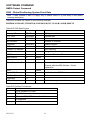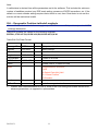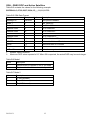
1
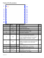
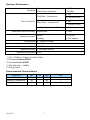
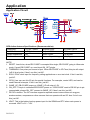
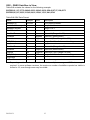
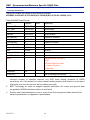
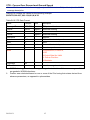
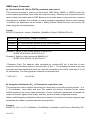
GLOBALSAT GPS Engine Board Hardware Data Sheet Product No : EB-5318RF Version 0.1 Globalsat Technology Corporation 16F., No. 186, Jian-Yi Road, Chung-Ho City, Taipei Hsien 235, Taiwan Tel: 886-2-8226-3799 Fax: 886-2-8226-3899 E-mail : [email protected] Website: www.globalsat.com.tw Issue Date 2011/10/4 2012/8/31 APPR CHECK Ray PREPARE Luwalk 1 Product Description Product Description EB-5318RF GPS module features high sensitivity, low power and ultra small form factor. This GPS module is powered by SiRF Star IV, it can provide you with superior sensitivity and performance even in urban canyon and dense foliage environment. With SiRF CGEE (Client Generated Extended Ephemeris) technology, it predicts satellite positions for up to 3 days and delivers CGEE-start time of less than 15 seconds under most conditions, without any network assistance. Besides, MicroPower Mode allows GPS module to stay in a hot-start condition nearly continuously while consuming very little power. EB-5318RF is suitable for the following applications: Automotive navigation Personal positioning Fleet management Mobile phone navigation Marine navigation Product Features SiRF Star IV high performance GPS Chipset Very high sensitivity (Tracking Sensitivity: -163 dBm) Extremely fast TTFF (Time To First Fix) at low signal level Support UART/I2C interface( Default UART) Built-in LNA(with in CHIP) Compact size (15.2mm * 14 mm * 2.4mm) suitable for space-sensitive application One size component, easy to mount on another PCB board Support NMEA 0183 V3.0 (GGA, GSA, GSV, RMC, VTG, GLL, ZDA) Support OSP protocol MEMS Support : 3-axis Magnetometer for compass heading for “Point and Tell” feature MicroPower Mode(MPM) : Reduce MPM current consumption from <500 uA to < 125 uA Support SBAS (WASS, EGNOS, MSAS, GAGAN) 2012/8/31 2 Product Pin Description PIN Number(s) Name Type Description 1,3,9,18,19 GND P 2 RF IN RF 4 RESET_N I System reset (active low) 5 VCC P Main power supply to the engine board. 6 P Backup battery supply voltage 7,8 V_BAT NC 10 BOOTSEL I Set this pin to high for programming flash. O This is the main transmits channel for outputting navigation and measurement data to user’s navigation software or user written software. Output TTL level, 0V ~ 2.85V. This is the main receive channel for receiving software commands to the engine board from SiRFdemo software or from user written software. 11 TXD Note Ground. GPS antenna input EB-5318RF reverse pin 12 RXD I 13 DR_I2C_DIO I/O 14 DR_I2C_CLK I/O 15 TIMEPULSE O One pulse per second output.(1PPS) 16 ON_OFF I ON_OFF pin is used to command the EB-5318RF to turn on or off 2 17 WAKE_UP O System power on, 1.8V output . 3 Host I2C Interface. Support MEMS Sensor , 1.8V Level <Note> 2012/8/31 3 1,4 1. GPIO is 1.8V Level 2. The ON_OFF pin commands the EB-5318RF ON or OFF. The turn ON command is a hardware feature of the Power Control FSM when sensing a rising edge on the pin. The turn OFF command is a software feature based on interrupts related to rising and/or falling edges and/or sensing of pin levels. 3. The WAKE_UP pin is an output from the EB-5318RF used to enable an external PMIC. A low on this output indicates that the EB-5318RF is in one of its low-power states (KA-only, Hibernate, or Standby mode) and requires no more than 60µA of current on the VIO_18 input. A high on this output indicates that the EB-5318RF is in operational mode requiring an external regulator to provide enough current on both the VIO_18 and VREG_18 inputs to handle the peak current requirements of the EB-5318RF. 4. The DR mode I2C interface provides support for dead reckoning (DR) and code upload. The port has 2 pins, DR_DIO and DR_CLK, both pins are pseudo open-drain and require pull-up resistors on the external bus. Electrical Specification Absolute Maximums Ratings Parameter Min. Typ. Max. Conditions Unit Main power supply(VCC) 3.1 3.3 3.5 V Backup battery supply 2.0 3.5 V POWER Supply Main power supply Current 45 50 55 GPS is not 3D Fixed. mA 35 38 45 GPS is 3D Fixed. mA RF POWER Supply VCC V 50 Ω 1.575 Ghz RF Input Input Impedance Operating Frequency DC Electrical characteristics Parameter Symbol Min. Typ. High Level Input Voltage VI H 0.7*VCC 3.6 V Low Level Input Voltage VI L -0.4 0.45 V High Level Output Voltage VOH 0.75*Vgcc Vgcc V Low Level Output Voltage VOL 0.4 V High Level Output Current IOH 2 mA Low Level Output Current IOL 2 mA Vgcc is SiRF Star IV Chip power input, 1.8V Vin. 2012/8/31 4 Max. Conditions Units Receiver Performance Sensitivity -163dBm Tracking : Autonomous acquisition : -160 dBm < 35s Cold Start – Autonomous Time-To-First-Fix1 <15s (with CGEE) < 35s Warm Start – Autonomous2 < 15s(with CGEE) Hot Start – Autonomous3 < 1s Horizontal Position Accuracy4 Autonomous Velocity Accuracy5 < 2.5m Speed < 0.01 m/s Heading < 0.01 degrees Reacquisition 0.1 second, average Update Rate 1 Hz / 5 Hz Maximum Altitude < 18,000 meter Maximum Velocity < 515 meter/ second Maximum Acceleration < 4G <Note> 1. 50% -130dBm Fu 0.5ppm Tu ±2s Pu 30Km 2. Commanded Warm START 3. Commanded Hot START 4. 50% 24hr static, -130dBm 5. 50% @ 30m/s Environmental Characteristics Parameter Max Unit 5 95 Operation Temperature -40 85 % non-condensing ℃ Storage Temperature -40 85 ℃ Humidity Range 2012/8/31 Min Typ 5 Physical Characteristic Type 19-pin stamp holes Dimensions 15.2mm * 14 mm * 2.4mm 2012/8/31 6 Application Application Circuit GPS Active Antenna Specifications (Recommendation) Frequency: 1575.42 + 2MHz Amplifier Gain: 18~22dB Typical Axial Ratio: 3 dB Typical Output VSWR: 2.0 Max. Output Impedance: 50Ω Noise Figure: 2.0 dB Max Polarization: Antenna Input Voltage: 3.3V (Typ.) RHCP NOTE: 1. RESET: Low Active, when EB-5318RF is accepted this single, EB-5318RF going to Hibernate mode. If want EB-5318RF up, need input ON_OFF single. 2. TIMEMARK: One pulse per second output. When EB-5318RF is 3D Fixed, this pin will output 1uS Hi level pulse. If don’t use this, just NC. 3. ECLK: ECLK clock input for frequency aiding applications or as a test clock. If don’t use this, just NC. 4. GPIO: User can use this I/O pin for special functions. For example, control LED, and can be used External Interrupts. If don’t use this, just NC. 5. WAKE_UP: EB-5318RF power on, WAKE_UP will output 1.8V. 6. ON_OFF: This pin is controlled EB-5318RF power on. If EB-5318RF want to EB-365 pin to pin compactable, please ON_OFF connect to WAKE_UP. If don’t use this, just NC. 7. DR I2C interface: The I2C interface supports required sensor instruments such as gyros, accelerometers, compasses or other sensors that can operate with an I2C bus. If don’t use this, just NC. 8. VBAT: This is the battery backup power input for the SRAM and RTC when main power is removed. VBAT is 2V ~ 3.5V. 2012/8/31 7 OPERATING Description RF_IN This pin receives signal of GPS analog via external active antenna. It has to be a controlled impedance trace at 50ohm. Do not have RF traces closed the other signal path and routing it on the top layer. Keep the RF traces as short as possible. ON_OFF The ON_OFF pin commands the EB-5318RF ON or OFF. There are multiple methods of connecting this pin for different applications in order to minimise host resource requirements. The ON_OFF pin is used to command the EB-5318RF to turn on or off: The turn on command is a hardware feature of the Power Control FSM based on sensing a rising edge on the pin. The turn off command is a software feature based on interrupts related to rising and/or falling edges and/ or sensing of pin levels. (Not currently supported.) The ON_OFF pin processing is carried out by GND This is Ground pin for the baseband circuit. VBAT This is the battery backup power input for the SRAM and RTC when main power is off. Without the external backup battery, EB-365 will always execute a cold star after turning on. To achieve the faster start-up offered by a hot or warm start, a battery backup must be connected. The battery voltage should be between 2.0V and 3.5V. the Power Control FSM. The ON_OFF rising edge event during low power modes is recorded in a status register that is subsequently read by the processor once it is running. When the processor is running at the time of an ON_OFF event, the processor can poll the status or set-up an interrupt. NC EB-5318RF reserves pin, Just NC. WAKE_UP VCC This is the main power supply to the engine board. (3.1Vdc to 3.5Vdc) System power controller, when EB-5318RF Power ON, this pin will output 1.8Vdc. TXD This is the main transmits channel for outputting navigation and measurement data to user’s navigation software or user written software. Output is TTL level, 0V ~ 2.85V. RESET Low Active, when EB-5318RF is accepted this single, EB-5318RF going to Hibernate mode. If want EB-5318RF up, need input ON_OFF single. RXD This is the main channel for receiving software commands from SiRFdemo software or from your proprietary software. TIMEPULSE This pin provides one pulse-per-second output from the board, which is synchronized to GPS time. This is not available in Trickle Power mode. If do not use it, Just NC. 2012/8/31 DR I2C Interface The I2C host port interface supports: 8 Operation up to 400kbps Individual transmit and receive FIFO lengths of 64B ■ The default I2C address values are: Rx: 0x60 Tx: 0x62 Multi-master I2C mode is supported by default. Dead reckoning applications support the DR I2C interface. The I2C interface supports required sensor instruments such as gyros, 2012/8/31 accelerometers, compasses or other sensors that can operate with an I2C bus. DRI2C interface supports: Typical data lengths (command + in/data out) of several bytes Standard I2C bus maximum data rate 400kbps Minimum data rate 100kbps 9 SOFTWARE COMMAND NMEA Output Command GGA - Global Positioning System Fixed Data Note – Fields marked in italic red apply only to NMEA version 2.3 (and later) in this NMEA message description Table B-2 contains the values for the following example: $GPGGA,161229.487,3723.2475,N,12158.3416,W,1,07,1.0,9.0,M,-34.2,M,,0000*18 Table B-2 GGA Data Format Name Example Units Description Message ID $GPGGA GGA protocol header UTC Time 161229.487 hhmmss.sss Latitude 3723.2475 ddmm.mmmm N/S Indicator N N=north or S=south Longitude 12158.3416 dddmm.mmmm E/W Indicator W E=east or W=west Position Fix Indicator 1 See Table B-3 Satellites Used 07 Range 0 to 12 HDOP 1.0 Horizontal Dilution of Precision MSL Altitude 9.0 meters Units M meters Geoid Separation1 -34.2 meters Units M meters Age of Diff. Corr. second Diff. Ref. Station ID 0000 Checksum *18 <CR><LF> Geoid-to-ellipsoid separation. Ellipsoid altitude=MSL Altitude + Geoid Separation Null fields when DGPS is not used End of message termination Table B-3 Position Fix Indicator Value Description 0 Fix not available or invalid 1 GPS SPS Mode, fix valid 2 Differential GPS, SPS Mode , fix valid 3 Not supported 6 Dead Reckoning Mode, fix valid 2012/8/31 10 Note: A valid status is derived from all the parameters set in the software. This includes the minimum number of satellites required, any DOP mask setting, presence of DGPS corrections, etc. If the default or current software setting requires that a factor is met, then if that factor is not met the solution will be marked as invalid. GLL - Geographic Position-Latitude/Longitude Note – Fields marked in italic red apply only to NMEA version 2.3 (and later) in this NMEA message description Table B-4 contains the values for the following example: $GPGLL,3723.2475,N,12158.3416,W,161229.487,A,A*41 Table B-4 GLL Data Format Name Example Message ID $GPGLL GLL protocol header Latitude 3723.2475 ddmm.mmmm N/S Indicator n N=north or S=south Longitude 12158.3416 dddmm.mmmm E/W Indicator W E=east or W=west UTC Position 161229.487 hhmmss.sss Status A A=data valid or V=data not valid Mode A A=Autonomous, D=DGPS, E=DR N=Output Data Not Valid R= Coarse Position1 S=Simulator Checksum *41 <CR><LF> 1. Units Description End of message termination Position was calculated based on one or more of the SVs having their states derived from almanac parameters, as opposed to ephemerides. 2012/8/31 11 GSA - GNSS DOP and Active Satellites Table B-5 contains the values for the following example: $GPGSA,A,3,07,02,26,27,09,04,15,,,,,,1.8,1.0,1.5*33 Table B-5 GSA Data Format Name Example Message ID $GPGSA GSA protocol header Mode 1 A See Table B-6 Mode 2 3 See Table B-7 Satellite Used1 07 Sv on Channel 1 1 02 Sv on Channel 2 Satellite Used Units Description ….. Satellite Used1 Sv on Channel 12 2 1.8 Position dilution of Precision 2 1.0 Horizontal dilution of Precision 2 VDOP 1.5 Vertical dilution of Precision Checksum *33 PDOP HDOP <CR><LF> 1. 2. End of message termination Satellite used in solution. Maximum DOP value reported is 50. When 50 is reported, the actual DOP may be much larger. Table B-6 Mode1 Value Description M Manual-forced to operate in 2D or 3D mode A 2Dautomatic-allowed to automatically switch 2D/3D Table B-7 Mode 2 Value Description 1 Fix Not Available 2 2D (<4 SVs used) 3 3D (>3 SVs used) 2012/8/31 12 GSV - GNSS Satellites in View Table B-8 contains the values for the following example: $GPGSV,2,1,07,07,79,048,42,02,51,062,43,26,36,256,42,27,27,138,42*71 $GPGSV,2,2,07,09,23,313,42,04,19,159,41,15,12,041,42*41 Table B-8 GSV Data Format Name Example Message ID Number of Messages Message Number1 Satellites in View 1 1 Units Description $GPGSV GSV protocol header 2 Range 1 to 3 1 Range 1 to 3 07 Satellite ID 07 Channel 1(Range 1 to 32) Elevation 79 degrees Channel 1(Maximum90) Azimuth 048 degrees Channel 1(True, Range 0 to 359) SNR(C/No) 42 dBHz Range 0 to 99,null when not tracking ……. ……. Satellite ID 27 Elevation 27 Degrees Channel 4(Maximum90) Azimuth 138 Degrees Channel 4(True, Range 0 to 359) SNR(C/No) 42 dBHz Checksum *71 <CR><LF> 1. Channel 4 (Range 1 to 32) Range 0 to 99,null when not tracking End of message termination Depending on the number of satellites tracked, multiple messages of GSV data may be required. In some software versions, the maximum number of satellites reported as visible is limited to 12, even though more may be visible. 2012/8/31 13 RMC - Recommended Minimum Specific GNSS Data Note – Fields marked in italic red apply only to NMEA version 2.3 (and later) in this NMEA message description Table B-9 contains the values for the following example: $GPRMC,161229.487,A,3723.2475,N,12158.3416,W,0.13,309.62,120598,,,A*10 Table B-9 RMC Data Format Name Example Units Description Message ID $GPRMC RMC protocol header UTC Time 161229.487 hhmmss.sss Status1 A A=data valid or V=data not valid Latitude 3723.2475 ddmm.mmmm N/S Indicator N N=north or S=south Longitude 12158.3416 dddmm.mmmm E/W Indicator W E=east or W=west Speed Over Ground 0.13 knots Course Over Ground 309.62 degrees True Date 120598 Magnetic Variation2 ddmmyy degrees E=east or W=west 2 East/West Indicator E E=east Mode A A=Autonomous, D=DGPS, E=DR N=Output Data Not Valid R= Coarse Position3 S=Simulator Checksum *10 <CR><LF> 1. 2. 3. End of message termination A valid status is derived from all the parameters set in the software. This includes the minimum number of satellites required, any DOP mask setting, presence of DGPS corrections, etc. If the default or current software setting requires that a factor is met, then if that factor is not met the solution will be marked as invalid. SiRF Technology Inc. does not support magnetic declination. All “course over ground” data are geodetic WGS84 directions relative to true North. Position was calculated based on one or more of the SVs having their states derived from almanac parameters, as opposed to ephemerides. 2012/8/31 14 VTG - Course Over Ground and Ground Speed Note – Fields marked in italic red apply only to NMEA version 2.3 (and later) in this NMEA message description Table B-10 contains the values for the following example: $GPVTG,309.62,T,,M,0.13,N,0.2,K,A*23 Table B-10 VTG Data Format Name Example Message ID $GPVTG Course 309.62 Reference T Course Units Description VTG protocol header degrees Measured heading True degrees Measured heading Magnetic1 Reference M Speed 0.13 Units N Speed 0.2 Units K Kilometers per hour Mode A A=Autonomous, D=DGPS, E=DR N=Output Data Not Valid R= Coarse Position2 S=Simulator Checksum *23 <CR><LF> 1. 2. knots Measured horizontal speed Knots Km/hr Measured horizontal speed End of message termination SiRF Technology Inc. does not support magnetic declination. All “course over ground” data are geodetic WGS84 directions. Position was calculated based on one or more of the SVs having their states derived from almanac parameters, as opposed to ephemerides. 2012/8/31 15 ZDA - Time and Date This message is included only with systems which support a time-mark output pulse identified as "1PPS". Outputs the time associated with the current 1PPS pulse. Each message is output within a few hundred ms after the 1PPS pulse is output and tells the time of the pulse that just occurred. Table B-11 contains the values for the following example: $GPZDA,181813,14,10,2003,,*4F<CR><LF> Table B-11: ZDA Data Format Name Example Message ID $GPZDA UTC Time 181813 Unit Description ZDA protocol header The UTC time units are: hh=UTC hours from 00 to 23 mm=UTC minutes from 00 to 59 ss=UTC seconds from 00 to 59 Either using valid IONO/UTC or estimated from default hhmmss leap seconds Day 14 Day of the month, range 1 to 31 Month 10 Month of the year, range 1 to 12 Year 2003 Year Local zone hour1 hour Offset from UTC (set to 00) Local zone minutes1 minute Offset from UTC (set to 00) Checksum *4F <CR><LF> 1. End of message termination Not supported by CSR, reported as 00. 2012/8/31 16 NMEA Input Command A). Set Serial Port ID: 100 Set PORTA parameters and protocol This command message is used to set the protocol (SiRF Binary, NMEA, or USER1) and/or the communication parameters (baud, data bits, stop bits, parity). Generally, this command would be used to switch the module back to SiRF Binary protocol mode where a more extensive command message set is available. For example, to change navigation parameters. When a valid message is received, the parameters will be stored in battery backed SRAM and then the receiver will restart using the saved parameters. Format: $PSRF100,<protocol>,<baud>,<DataBits>,<StopBits>,<Parity>*CKSUM<CR><LF> <protocol> 0=SiRF Binary, 1=NMEA, 4=USER1 <baud> 1200, 2400, 4800, 9600, 19200, 38400 <DataBits> 8,7. Note that SiRF protocol is only valid f8 Data bits <StopBits> 0,1 <Parity> 0=None, 1=Odd, 2=Even Example 1: Switch to SiRF Binary protocol at 9600,8,N,1 $PSRF100,0,9600,8,1,0*0C<CR><LF> Example 2: Switch to User1 protocol at 38400,8,N,1 $PSRF100,4,38400,8,1,0*38<CR><LF> **Checksum Field: The absolute value calculated by exclusive-OR the 8 data bits of each character in the Sentence, between, but excluding “$” and “*”. The hexadecimal value of the most significant and least significant 4 bits of the result are convertted to two ASCII characters (0-9, A-F) for transmission. The most significant character is transmitted first. **<CR><LF> : Hex 0D 0A B). Navigation lnitialization ID:101 Parameters required for start This command is used to initialize the module for a warm start, by providing current position (in X, Y, Z coordinates),clock offset, and time. This enables the receiver to search for the correct satellite signals at the correct signal parameters. Correct initialization parameters will enable the receiver to acquire signals more quickly, and thus, produce a faster navigational solution. When a valid Navigation Initialization command is received, the receiver will restart using the input parameters as a basis for satellite selection and acquisition. Format: $PSRF101,<X>,<Y>,<Z>,<ClkOffset>,<TimeOfWeek>,<WeekNo>,<chnlCount>,<ResetCfg>*CK 2012/8/31 17 SUM<CR><LF> <X> X coordinate position INT32 <Y> Y coordinate position INT32 <Z> Z coordinate position INT32 <ClkOffset> Clock offset of the receiver in Hz, Use 0 for last saved value if available. If this is unavailable, a default value of 75000 for GSP1, 95000 for GSP 1/LX will be used. INT32 <TimeOf Week> GPS Time Of Week UINT32 <WeekNo> GPS Week Number UINT16 ( Week No and Time Of Week calculation from UTC time) <chnlCount> Number of channels to use.1-12. If your CPU throughput is not high enough, you could decrease needed throughput by reducing the number of active channels UBYTE <ResetCfg> bit mask 0×01=Data Valid warm/hot start=1 0×02=clear ephemeris warm start=1 0×04=clear memory. Cold start=1 UBYTE Example: Start using known position and time. $PSRF101,-2686700,-4304200,3851624,96000,497260,921,12,3*7F C). Set DGPS Port ID: 102 Set PORT B parameters for DGPS input This command is used to control Serial Port B that is an input only serial port used to receive RTCM differential corrections. Differential receivers may output corrections using different communication parameters. The default communication parameters for PORT B are 9600Baud, 8data bits, 0 stop bits, and no parity. If a DGPS receiver is used which has different communication parameters, use this command to allow the receiver to correctly decode the data. When a valid message is received, the parameters will be stored in battery backed SRAM and then the receiver will restart using the saved parameters. Format: $PSRF102,<Baud>,<DataBits>,<StopBits>,<Parity>*CKSUM<CR><LF> 2012/8/31 18 <baud> 1200,2400,4800,9600,19200,38400 <DataBits> 8 <StopBits> 0,1 <Parity> 0=None, Odd=1,Even=2 Example: Set DGPS Port to be 9600,8,N,1 $PSRF102,9600,8,1.0*12 D). Query/Rate Control ID: 103 Query standard NMEA message and/or set output rate This command is used to control the output of standard NMEA message GGA, GLL, GSA, GSV, RMC, VTG. Using this command message, standard NMEA message may be polled once, or setup for periodic output. Checksums may also be enabled or disabled depending on the needs of the receiving program. NMEA message settings are saved in battery backed memory for each entry when the message is accepted. Format: $PSRF103,<msg>,<mode>,<rate>,<cksumEnable>*CKSUM<CR><LF> <msg> 0=GGA, 1=GLL, 2=GSA, 3=GSV, 4=RMC, 5=VTG 6=MSS(if internal beacon is supported) 7=Not defined 8=ZDA(if 1PPS output supported) 9=Not defined <mode> 0=SetRate 1=Query 2=ABP On 3=ABP Off <rate> Output every <rate>seconds, off=0,max=255 <cksumEnable> 0=disable Checksum,1=Enable checksum for specified message Example 1: Query the GGA message with checksum enabled $PSRF103,00,01,00,01*25 Example 2: Enable VTG message for a 1Hz constant output with checksum enabled $PSRF103,05,00,01,01*20 Example 3: Disable VTG message $PSRF103,05,00,00,01*21 2012/8/31 19 E). LLA Navigation lnitialization ID: 104 Parameters required to start using Lat/Lon/Alt This command is used to initialize the module for a warm start, by providing current position (in Latitude, Longitude, Altitude coordinates), clock offset, and time. This enables the receiver to search for the correct satellite signals at the correct signal parameters. Correct initialization parameters will enable the receiver to acquire signals more quickly, and thus, will produce a faster navigational soution. When a valid LLA Navigation Initialization command is received, the receiver will restart using the input parameters as a basis for satellite selection and acquisition. Format: $PSRF104,<Lat>,<Lon>,<Alt>,<ClkOffset>,<TimeOfWeek>,<WeekNo>,<ChannelCount>, <ResetCfg>*CKSUM<CR><LF> <Lat> Latitude position, assumed positive north of equator and negative south of equator float, possibly signed <Lon> Longitude position, it is assumed positive east of Greenwich and negative west of Greenwich Float, possibly signed <Alt> Altitude position float, possibly signed <ClkOffset> Clock Offset of the receiver in Hz, use 0 for last saved value if available. If this is unavailable, a default value of 75000 for GSP1, 95000 for GSP1/LX will be used. INT32 <TimeOfWeek> GPS Time Of Week UINT32 <WeekNo> GPS Week Number UINT16 <ChannelCount> Number of channels to use. 1-12 UBYTE <ResetCfg> bit mask 0×01=Data Valid warm/hot starts=1 0×02=clear ephemeris warm start=1 0×04=clear memory. Cold start=1 UBYTE Example: Start using known position and time. $PSRF104,37.3875111,-121.97232,0,96000,237759,922,12,3*37 F). Development Data On/Off ID: 105 Switch Development Data Messages On/Off Use this command to enable development debug information if you are having trouble getting commands accepted. Invalid commands will generate debug information that should enable the user to determine the source of the command rejection. Common reasons for input command rejection are invalid checksum or parameter out of specified range. This setting is not preserved across a module reset. 2012/8/31 20 Format: $PSRF105,<debug>*CKSUM<CR><LF> <debug> Example: Debug On Example: Debug Off 0=Off, 1=On $PSRF105,1*3E $PSRF105,0*3F G). Select Datum ID: 106 Selection of datum to be used for coordinate Transformations GPS receivers perform initial position and velocity calculations using an earth-centered earth-fixed (ECEF) coordinate system. Results may be converted to an earth model (geoid) defined by the selected datum. The default datum is WGS 84 (World Geodetic System 1984) which provides a worldwide common grid system that may be translated into local coordinate systems or map datums. (Local map datums are a best fit to the local shape of the earth and not valid worldwide.) Examples: Datum select TOKYO_MEAN $PSRF106,178*32 Name Example Unit Message ID $PSRF106 PSRF106 protocol header Datum 178 21=WGS84 178=TOKYO_MEAN 179=TOKYO_JAPAN 180=TOKYO_KOREA 181=TOKYO_OKINAWA Debug Checksum *32 <CR><LF> 2012/8/31 Description End of message termination 21 PCB Layout Recommend Recommended Layout PAD Unit: mm Tolerance: 0.1mm PCB Layout Recommendations Do not routing the other signal or power trace under the engine board. RF: This pin receives signal of GPS analog via external active antenna .It has to be a controlled impedance trace at 50ohm. Do not place the RF traces close to the other signal path and not routing it on the top layer. Keep the RF traces as short as possible. Antenna: Keep the active antenna on the top of your system and confirm the antenna radiation pattern、axial ratio、power gain、noise figure、VSWR are correct when you Setup the antenna in your case. 2012/8/31 22 Recommended Reflow Profile: 150±10[℃] Pre heating temperature: Pre heating time: 90±30[sec.] 235±5[℃] Heating temperature: Heating time: 10±1[sec.] Peak temperature must not exceed 240℃ and the duration of over 200℃ should be 30±10 Seconds. 2012/8/31 23 Appendix LABEL Artwork A: Brand: GLOBALSAT B: MODULE Model: EB-5318RF B-1: R = UART, I = I2C I/F E = Included EEPROM F = Included FLASH C: CHIP Type: SiRF IV D: Bar code E: Serial Number: □ □ □ □□□□ Product NO (HEX) Place of origin, T= Taiwan, C=China Product Month, 123456789XYZ, X->Oct,Y->Nov,Z->Dec Product Year 2012/8/31 24