1
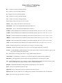
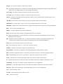
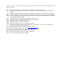
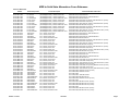
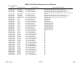
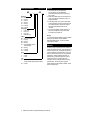
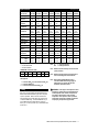
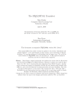
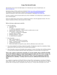
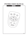
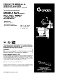
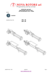
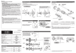
Using This Retrofit Guide
This document is best viewed with Adobe Reader 6.0. To obtain the latest version of Adobe Reader, visit
http://www.adobe.com
Specification sheets on Watlow product may be obtained at http://www.watlow.com/literature/specsheets/
User Manuals on Watlow product may be obtained at http://www.watlow.com/literature/prodtechinfo/
Additional information on other Watlow products may be obtained by visiting http://www.watlow.com/
To locate a controller, search on the part number such as 965A-1CD0-00RG. Use the Help feature in Adobe Reader on
how to search documents.
If there are multiple listings, then the retrofit is conditional upon field use. Select the appropriate selection. The User’s
Manual is included at the bottom of this document when available.
Before selecting a replacement controller:
1.
Know the application.
• Temperature range
• Sensor type
• Is the sensor upgradable if required?
• Additional input requirements – remote set points, secondary sensor or events
• Output required – control, alarm, event
• Is the power-switching device upgradable?
• Operating voltage of controller
• Mounting requirements – panel space
• Is a safety limit device required?
2.
Know the product.
• Inputs – type and number of
• Control function – direct (cool) or reverse (heat)
• Outputs – switched DC, SSR, or mechanical relay
• Communication requirements
• Which control features are required? (cascade, slidewire, differential, remote control, other)
3.
Use your best judgment for selecting a replacement controller. All applications require close examination of input,
output and the control mode needs to have the controller function properly.
4.
Safety: Remember to make sure all redundant safety equipment is in place and working when retrofitting equipment.
If a system has been retrofitted without the proper safety equipment, you could be liable if an accident occurs.
This is only a guide to replacement controllers. If you have doubts, please call (507) 454-5300
and ask for technical support or email [email protected]. We’re here to help. The
suggested replacement will differ in fit and form. Please review the replacement controller
specifications for suitability. Carefully check the notes for additional information that may
apply.
Your comments or suggestions on the Retrofit Guide are welcome. Please send comments or corrections to: Technical
Writer, Watlow Controls, 1241 Bundy Boulevard, P.O. Box 5580, Winona, MN 55987-5580; phone (507) 454-5300; fax
(507) 452-4507. This Retrofit Guide is copyrighted by Watlow Winona, Inc., © February 2004 with all rights reserved. (1455)
Abbreviation & Terminology
(as used in this document)
0.5 – 0.5 amperes of current switching capability
2A – 2 amperes of current switching capability
5A - 5 amperes of current switching capability
10A – 10 amperes of current switching capability
15A – 15 amperes of current switching capability
12-24 – Supply voltage can be between 12 to 24 Volts
100-240 – Supply voltage can be between 100 to 240 Volts
100 ohm DIN – refers to 100-ohm platinum RTD that has a DIN curve.
100 ohm JIS – refers to 100-ohm platinum RTD that has a JIS curve.
1/32 DIN – Deutsche Industrial Norm standard for panel mounted controller, hole size is cut to 1.78”w x 0.88”h.
1/16 DIN – Deutsche Industrial Norm standard for panel mounted controller, hole size is cut to 1.78”w x 1.77”h.
1/8V DIN – Deutsche Industrial Norm standard for panel mounted controller, hole size is cut to 1.78”w x 3.63”h.
1/8H DIN – Deutsche Industrial Norm standard for panel mounted controller, hole size is cut to 3.63”w x 1.77”h”
1/8S DIN – Deutsche Industrial Norm standard for panel mounted controller, hole size is cut to 2.68”w x 2.68”h.
¼ DIN – Deutsche Industrial Norm standard for panel mounted controller, hole size is cut to 3.63”w x 3.63”h.
Action – determines the direction of control. Heat (reverse acting) or Cool (direct acting).
Auto Reset – the limit will automatically reset on a power cycle but requires manual reset on limit trip.
Cascade – a control algorithm in which the output of one control loop provides a set point for another loop. The second
loop, in turn, determines the control action.
Ch – Channel refers to an analog input. There are single and dual channel controllers.
Control Mode – the method that a controller uses to switch the outputs such as PID, ON/OFF, and Manual.
Differential - control algorithm in which the output is based on the difference of the inputs plus set point.
DIN – Deutsche Industrial Norm, a set of technical, scientific and dimensional standards developed in Germany. RTD
sensors with the DIN curve change resistance at a rate of 0.00385 ohms/ohms/C.
DIN Rail – standard DIN EN50022 mounting method for attaching devices onto a metal rail.
Fixed – refers to a set point that is fixed at one value.
High Limit - device will deactivate output on a temperature rise above set point.
Inductive Load – any device that has a wire winding such as solenoids, electromechanical relays or transformers.
Input – refers to the sensor types that may be connected.
Integral – the set point in integral (on board) to the controller.
JIS – Joint Industrial Standards, a set of technical, scientific and dimensional standards developed in Japan. RTD sensors
with the JIS curve change resistance at a rate of 0.00396 ohms/ohms/C.
Line Voltage – the voltage required powering the electronics of the controller.
Low Limit - device will deactivate output on a temperature drop below set point.
On/Off – a method of control that turns the output full on until set point is reached and then off until the process error
exceeds the hysteresis.
Open Brd – the form factor of this controller is an open circuit board mounted on four standoffs.
Manual Reset – the limit must be reset on a power cycle and requires manual reset on limit trip.
Multi RSP – multiple remote set potentiometers were supported. Each allowed the set point to be selected and adjusted.
Relay – refers to an electromechanical relay.
Remote – set point is adjusted using a remote potentiometer.
Panel – the form factor of this controller is mounted through a hole cut in the panel.
PI – Proportional and Integral, a control mode with two functions: proportional action dampens the systems response,
and integral corrects for droop.
PID – Proportional, Integral, and Derivative, a control mode with three functions: proportional action dampens the
systems response, integral corrects for droop, and derivative prevents overshoot and undershoot.
Potted – the circuit board and electronics are encased in epoxy.
Proc – Process input may accept 0-5, 1-5, 0-10 volts or 0-20 and 4-20 mA.
Profiling – Controller will perform a sequence of programmed steps.
Programmable – The feature is changeable in the field through jumpers and/or parameter selection.
RTD – Resistance Temperature Detector, a sensor that is 100 ohms at 0 degrees C and made of platinum material.
SSR – Solid State Relay, these devices will switch AC voltage only and require a load to latch on.
Sw DC – Switched DC, a time proportioning DC output used to drive DC input solid state relays.
t/c – Thermocouple sensor device made by joining two dissimilar metals whose standards is identified by a letter.
Temp Range – the range over which the controller could have the set point adjustment.
Thermistor – a sensor that changes resistance as the temperature changes. Similar but not the same as an RTD.
Universal – Input can be a thermocouple, 100 ohm DIN RTD or process (volts or milliamperes)
VAC – Volts Alternating Current
VAC/DC- Volts Alternating Current or Direct Current
VDC – Volts Direct Current
VTB Sw DC – Variable Time Base Switched Direct Current, a time proportioning DC output where the cycle time is
variable.
These notes are used to signify areas of concern in changing to a retrofit choice. These notes are also printed at the end
of the retrofit listing.
Note 1: Retrofit controller requires a substitution of a 100 Ohm RTD sensor for the thermistor.
Note 2: Mounting and dimensions of retrofit controller are different. Verify that sufficient panel space and depth is
available.
Note 3: Retrofit controller outputs are different. Add external interposing mechanical or solid state relay if applicable.
Note 4: Retrofit controller has a programmable, not fixed set point. Lock set point using controller's lockout parameter.
Note 5: For DIN rail mounting or sub-panel mounting, purchase DIN rail adapter p/n 0822-0586-P001 for 1/32 DIN or
p/n 0822-0586-P002 for 1/16 DIN.
Note 6: Add a suppressor, Watlow p/n 0804-0147-0000, for inductive loads.
Note 7: Retrofit does not have equivalent action (as example, no manual reset)
Note 8: Retrofit controller does not have dual dial scale.
Note 9: Hardware lockout is not available on retrofit.
Note 10: Retrofit controller does not have user selectable line voltage.
Note 11: Retrofit does not support remote set point or retransmit. Check if pins 13, 14, 15 or 16 have termination. If
wires are on these pins, select a different retrofit.
Note 12: Retrofit controller does not have user selectable control action.
Note 13: Solid state sensor required for humidity. See http://www.vaisala.com
Note 14: Retrofit controller does not have user selectable control mode.
Note 15: Use auxiliary event board A007-1732-F4B8
Note 16: Retrofit communications are different, consult specifications.
Note 17: Verify retrofit input range matches application.
MDR to Solid State Alternatives Cross Reference
HG Series Watlow Part
Number
HG30-1KD1-0000
HG30-4KD1-0000
HG30-6KD1-0000
HG30-9KD1-0000
HG30-1KD2-0000
HG30-4KD2-0000
HG30-6KD2-0000
HG30-9KD2-0000
HG30-1KD3-0000
HG30-4KD3-0000
HG30-6KD3-0000
HG30-9KD3-0000
HG35-1LD1-0000
HG35-4LD1-0000
HG35-6LD1-0000
HG35-9LD1-0000
HG35-1LD2-0000
HG35-4LD2-0000
HG35-6LD2-0000
HG35-9LD2-0000
HG35-1LD3-0000
HG35-4LD3-0000
HG35-6LD3-0000
HG35-9LD3-0000
HG50-1MD1-0000
HG50-4MD1-0000
HG50-6MD1-0000
HG50-9MD1-0000
HG50-1MD2-0000
HG50-4MD2-0000
HG50-6MD2-0000
HG50-9MD2-0000
HG50-1MD3-0000
HG50-4MD3-0000
HG50-6MD3-0000
HG50-9MD3-0000
HG60-1PD1-0000
HG60-4PD1-0000
HG60-6PD1-0000
HG60-9PD1-0000
HG60-1PD2-0000
HG60-4PD2-0000
HG60-6PD2-0000
HG60-9PD2-0000
HG60-1PD3-0000
HG60-4PD3-0000
HG60-6PD3-0000
HG60-9PD3-0000
Watlow Controls
Durakool Equivalent
LF-701120AC
LF-70124AC
LF-70124DC
LF-701208ACDV
LF2-701120AC
LF2-70124AC
LF2-70124DC
LF2-701208ACDV
LF3-701120AC
LF3-70124AC
LF3-70124DC
LF3-701208ACDV
1035A120AC
1035A24AC
1035A24DC
1035A208ACDV
2035A120AC
2035A24AC
2035A24DC
2035A208ACDV
3035A120AC
3035A24AC
3035A24DC
3035A208ACDV
1050A120AC
1050A24AC
1050A24DC
1050A208ACDV
2050A120AC
2050A24AC
2050A24DC
2050A208ACDV
3050A120AC
3050A24AC
3050A24DC
3050A208ACDV
1060APS120AC
1060APS24AC
1060APS24DC
1060APS208ACDV
2060APS120AC
2060APS24AC
2060APS24DC
2060APS208ACDV
3060APS120AC
3060APS24AC
3060APS24DC
3060APS208ACDV
Product Description
(30A NEW)(25A OLD), 1 POLE, 120VAC COIL
(30A NEW)(25A OLD), 1 POLE, 24VAC COIL
(30A NEW)(25A OLD), 1 POLE, 24VDC COIL
(30A NEW)(25A OLD), 1 POLE, 208/240VAC COIL
(30A NEW)(25A OLD), 2 POLE, 120VAC COIL
(30A NEW)(25A OLD), 2 POLE, 24VAC COIL
(30A NEW)(25A OLD), 2 POLE, 24VDC COIL
(30A NEW)(25A OLD), 2 POLE, 208/240VAC COIL
(30A NEW)(25A OLD), 3 POLE, 120VAC COIL
(30A NEW)(25A OLD), 3 POLE, 24VAC COIL
(30A NEW)(25A OLD), 3 POLE, 24VDC COIL
(30A NEW)(25A OLD), 3 POLE, 208/240VAC COIL
35A, 1 POLE, 120VAC COIL
35A, 1 POLE, 24VAC COIL
35A, 1 POLE, 24VDC COIL
35A, 1 POLE, 208/240VAC COIL
35A, 2 POLE, 120VAC COIL
35A, 2 POLE, 24VAC COIL
35A, 2 POLE, 24VDC COIL
35A, 2 POLE, 208/240VAC COIL
35A, 3 POLE, 120VAC COIL
35A, 3 POLE, 24VAC COIL
35A, 3 POLE, 24VDC COIL
35A, 3 POLE, 208/240VAC COIL
50A, 1 POLE, 120VAC COIL
50A, 1 POLE, 24VAC COIL
50A, 1 POLE, 24VDC COIL
50A, 1 POLE, 208/240VAC COIL
50A, 2 POLE, 120VAC COIL
50A, 2 POLE, 24VAC COIL
50A, 2 POLE, 24VDC COIL
50A, 2 POLE, 208/240VAC COIL
50A, 3 POLE, 120VAC COIL
50A, 3 POLE, 24VAC COIL
50A, 3 POLE, 24VDC COIL
50A, 3 POLE, 208/240VAC COIL
60A, 1 POLE, 120VAC COIL
60A, 1 POLE, 24VAC COIL
60A, 1 POLE, 24VDC COIL
60A, 1 POLE, 208/240VAC COIL
60A, 2 POLE, 120VAC COIL
60A, 2 POLE, 24VAC COIL
60A, 2 POLE, 24VDC COIL
60A, 2 POLE, 208/240VAC COIL
60A, 3 POLE, 120VAC COIL
60A, 3 POLE, 24VAC COIL
60A, 3 POLE, 24VDC COIL
60A, 3 POLE, 208/240VAC COIL
5/6/2004
Potential Solid State Alternatives
DB10-60K2-0000, CZ34-A60V-AC1, SSR-480-50A-AC1
DB10-60K1-0000, CZ34-A60V-AC2
DB10-60C0-0000, CZ34-A48V-DC1, SSR-480-50A-DC1
DB10-60K3-0000, SSR-480-50A-AC1
DC20-60K2-0000, CZ34-A60V-AC1 (2PCS.), SSR-480-50A-AC1 (2 PCS.)
DC20-60K1-0000, CZ34-A60V-AC2 (2 PCS.)
DC20-60C0-0000, CZ34-A48V-DC1 (2PCS.), SSR-480-50A-DC1 (2 PCS)
DC20-60K3-0000, SSR-480-50A-AC1 (2pcs.)
DC30-60K2-0000, CZ34-A60V-AC1 (3PCS.), SSR-480-50A-AC1 (3 PCS.)
DC30-60K1-0000, CZ34-A60V-AC2 (3 PCS.)
DC20-60C0-0000, CZ34-A48V-DC1 (3 PCS.), SSR-480-50A-DC1 (3 PCS)
DC30-60K3-0000, SSR-480-50A-AC1 (3 pcs.)
DC10-60K2-0000, CZ50-A48V-AC1, SSR-480-50A-AC1
DC10-60K1-0000, CZ50-A48V-AC2
DC10-60C0-0000, CZ50-A48V-DC1, SSR-480-50A-DC1
DC10-60K3-0000, SSR-480-50A-AC1
DC21-60K2-0000, CZ50-A48V-AC1 (2 PCS.),SSR-480-75A-AC1 (2 PCS.)
DC21-60K1-0000, CZ50-A48V-AC2 (2 PCS.)
DC21-60C0-0000, CZ50-A48V-DC1 (2 PCS.), SSR-480-75A-DC1 (2 PCS.)
DC21-60K3-0000, SSR-480-75A-AC1 (2 PCS.)
DC31-60K2-0000, CZ50-A48V-AC1 (3 PCS.),SSR-480-75A-AC1 (3 PCS.)
DC31-60K1-0000, CZ50-A48V-AC2 (3 PCS.)
DC31-60C0-0000, CZ50-A48V-DC1 (3 PCS.), SSR-480-75A-DC1 (3 PCS.)
DC31-60K3-0000, SSR-480-75A-AC1 (3 PCS.)
DC11-60K2-0000, SSR-480-75A-AC1
DC11-60K1-0000
DC11-60C0-0000, SSR-480-75A-DC1
DC11-60K3-0000, SSR-480-75A-AC1
DC21-60K2-0000, SSR-480-75A-AC1 (2 PCS.)
DC21-60K1-0000
DC21-60C0-0000, SSR-480-75A-DC1 (2 PCS.)
DC21-60K3-0000, SSR-480-75A-AC1 (2 PCS.)
DC31-60K2-0000, SSR-480-75A-AC1 (3 PCS.)
DC31-60K1-0000
DC31-60C0-0000, SSR-480-75A-DC1 (3 PCS.)
DC31-60K3-0000, SSR-480-75A-AC1 (3 PCS.)
Page 1
MDR to Solid State Alternatives Cross Reference
HG Series Watlow Part
Number
HG30-1AA2-0000
HG30-4AA2-0000
HG30-6AA2-0000
HG30-9AA2-0000
Durakool Equivalent
2030APS120AC
2030APS24AC
2030APS24DC
2030APS208ACDV
Product Description
30A, 2 POLE, 120VAC COIL
30A, 2 POLE, 24VAC COIL
30A, 2 POLE, 24VDC COIL
30A, 2 POLE, 208/240VAC COIL
HG30-1AA3-0000
HG30-4AA3-0000
HG30-6AA3-0000
HG30-9AA3-0000
HG80-1AB1-0000
HG80-4AB1-0000
HG80-6AB1-0000
HG80-9AB1-0000
HG80-1AB2-0000
HG80-4AB2-0000
HG80-6AB2-0000
HG80-9AB2-0000
HG80-1AB3-0000
HG80-4AB3-0000
HG80-6AB3-0000
HG80-9AB3-0000
HG1M-1AC1-0000
HG1M-4AC1-0000
HG1M-6AC1-0000
HG1M-9AC1-0000
HG1M-1AC2-0000
HG1M-4AC2-0000
HG1M-6AC2-0000
HG1M-9AC2-0000
HG1M-1AC3-0000
HG1M-4AC3-0000
HG1M-6AC3-0000
HG1M-9AC3-0000
HG2M-1AD1-0000
HG2M-4AD1-0000
HG2M-6AD1-0000
HG2M-9AD1-0000
HG2M-1AD2-0000
HG2M-4AD2-0000
HG2M-6AD2-0000
HG2M-9AD2-0000
HG2M-1AD3-0000
HG2M-4AD3-0000
HG2M-6AD3-0000
HG2M-9AD3-0000
3030APS120AC
3030APS24AC
3030APS24DC
3030APS208ACDV
CF-702
CF-701
CF-707
CF-713
CF2-702
CF2-701
CF2-708
CF2-713
CF3-702
CF3-701
CF3-708
CF3-713
CFC-718
CFC-717
CFC-723
CFC-734
CFC2-727
CFC2-726
CFC2-733
CFC2-734
CFC3-708
CFC3-707
CFC3-721
CFC3-734
DFC-301
DFC-307
DFC-310
DFC-311
DFC2-301
DFC2-307
DFC2-310
DFC2-311
DFC3-301
DFC3-307
DFC3-310
DFC3-311
30A, 3 POLE, 120VAC COIL
30A, 3 POLE, 24VAC COIL
30A, 3 POLE, 24VDC COIL
30A, 3 POLE, 208/240VAC COIL
80A, 1 POLE, 120VAC COIL
80A, 1 POLE, 24VAC COIL
80A, 1 POLE, 24VDC COIL
80A, 1 POLE, 208/240VAC COIL
80A, 2 POLE, 120VAC COIL
80A, 2 POLE, 24VAC COIL
80A, 2 POLE, 24VDC COIL
80A, 2 POLE, 208/240VAC COIL
80A, 3 POLE, 120VAC COIL
80A, 3 POLE, 24VAC COIL
80A, 3 POLE, 24VDC COIL
80A, 3 POLE, 208/240VAC COIL
100A, 1 POLE, 120VAC COIL
100A, 1 POLE, 24VAC COIL
100A, 1 POLE, 24VDC COIL
100A, 1 POLE, 208/240VAC COIL
100A, 2 POLE, 120VAC COIL
100A, 2 POLE, 24VAC COIL
100A, 2 POLE, 24VDC COIL
100A, 2 POLE, 208/240VAC COIL
100A, 3 POLE, 120VAC COIL
100A, 3 POLE, 24VAC COIL
100A, 3 POLE, 24VDC COIL
100A, 3 POLE, 208/240VAC COIL
150A, 1 POLE, 120VAC COIL
150A, 1 POLE, 24VAC COIL
150A, 1 POLE, 24VDC COIL
150A, 1 POLE, 208/240VAC COIL
150A, 2 POLE, 120VAC COIL
150A, 2 POLE, 24VAC COIL
150A, 2 POLE, 24VDC COIL
150A, 2 POLE, 208/240VAC COIL
150A, 3 POLE, 120VAC COIL
150A, 3 POLE, 24VAC COIL
150A, 3 POLE, 24VDC COIL
150A, 3 POLE, 208/240VAC COIL
Watlow Controls
Potential Solid State Alternatives
DC20-60K2-0000, ES40-3120-AC00, SSR-480-50A-AC1 (2PCS.)
DC20-60K1-0000, ES40-3024-AC00, CZ34-A48V-AC2 (2 PCS.)
DC20-60C0-0000, CZ34-A60V-DC1 (2PCS.), SSR-480-50A-DC1 (2 PCS.)
DC20-60K3-0000, ES40-3220-AC00, SSR-480-50A-AC1 (2 PCS.)
DC30-60K2-0000, ES40-3120-AC00, SSR-480-50A-AC1 (3 PCS.), CZ34-A48V-AC1
(3 PCS.)
DC30-60K1-0000, ES40-3024-AC00, CZ34-A48V-AC2 (3 PCS.)
DC30-60C0-0000, CZ34-A60V-DC1 (3 PCS.), SSR-480-50A-DC1 (3 PCS.)
DC20-60K3-0000, ES40-3220-AC00, SSR-480-50A-AC1 (3 PCS.)
DD10-60K2-0000
DD10-60K1-0000
DD10-60C0-0000
DD10-60K3-0000
DD10-60K2-0000 (2 PCS.)
DD10-60K1-0000 (2 PCS.)
DD10-60C0-0000 (2 PCS.)
DD10-60K3-0000 (2 PCS.)
DD10-60K2-0000 (3PCS.)
DD10-60K1-0000 (3 PCS.)
DD10-60C0-0000 (3 PCS.)
DD10-60K3-0000 (3 PCS.)
NA
NA
NA
NA
NA
NA
NA
NA
NA
NA
NA
NA
NA
NA
NA
NA
NA
NA
NA
NA
NA
NA
NA
NA
5/6/2004
Page 2
HG Series
Mercury Displacement Relay
User’s Manual
ISO 9001
Registered Company
Winona, Minnesota USA
Power Controls
Watlow Controls, 1241 Bundy Blvd., P.O. Box 5580, Winona, MN, USA 55987-5580, Phone: (507) 454-5300, Fax: (507) 452-4507
WMDR-XUMN-1097
June 1997
Supersedes: WMDR-XUMN Rev A00
Made in the U.S.A.
Printed on Recycled Paper 10% Postconsumer Waste
Dimensions
All 35, 50, and 60 Amp Models
30 Amp Models
HG30-XKDX-0000
1 Pole
#8-32
Binding
Head
Screw
#10-#14
A.W.G.
2.00
(51)
Dia.
3.58
(91)
1.94
(49)
1.63
(41)
.21 (5)
Dia.
Mounting
Hole
1.19
(30)
2.25
(57)
NOTE:
Watlow recommends that ring terminal lugs be used
with stranded wire
on all binding head
screw terminals.
“A”
Dimensions
4.62 (117)
4.62 (117)
5.12 (130)
HG35-XLDX-0000
HG50-XMDX-0000
HG60-XPDX-0000
Pressure
Connectors
#4-14 A.W.G.
#4-14 A.W.G.
#1 - 8 A.W.G.
1 Pole
Pressure
Connector
2.00
(51)
"A"
1.94
(49)
1.63
(41)
2 Pole
#8-32 Binding
Head Screw
#10-#14 A.W.G.
4.00
(102)
2.25
(57)
1.19
(30)
.20 (5)
Dia. Mtg.
Hole
2 Pole
.21 (5)
Wide Slot
For #10
Screw
Hole
2.65
(67)
1.94
(49)
Pressure
Connector
40°
Typ.
.21 (5)
Dia.
Mounting
Hole
3.13
(79)
2.62
(67)
4.00
(102)
.21 (5)
Wide Slot
For #10
Screw
Hole
40°
Typ.
.21 (5)
Dia. Mtg.
Hole For
#10 Screw
3 Pole
#8-32
Binding
Head Screw
#10-#14
A.W.G
4.00
(102)
.21 (5)
Wide
Slot
For#10
Screw
Hole 40°
Typ.
.21 (5)
Dia.
Mounting
Hole
3.25
(83)
3.75
(95)
.21 (5)
Wide Slot
For #10
Screw
Hole
40°
TYP.
.21
(5)
Dia. Mtg.
Hole For
#10
Screw
#10-32
Binding
Head
Screw
.25
Typ. Up To #10
A.W.G.
(6)
3.13
(79)
2.65
(67)
3.75
(95)
4.00
(102)
Mercury displacement relay must be
mounted vertically. Failure to do this will prevent the
contacts from turning off, which will supply full
voltage to the load. Failure to follow this guideline
could result in damage to equipment, and personal
injury or death.
ÓWARNING:
2
"A"
1.94
(49)
ÓWARNING:
Up
3.14
(80)
2.62
(67)
Pressure
Connector
3.75
(95)
Mounting
Slot
For #8 To
#10 Screw
3.13
(79)
4.00
(102)
3 Pole
Definite Purpose Relay Foot Print
HG30-XAAX-0000
2.16
(55)
2.65
(67)
2.65
(67)
1.94
(49)
3.13
(79)
4.00
(102)
"A"
1.94
(49)
3.43
(87)
Watlow Series HG Mercury Displacement Relay User’s Manual
Mercury displacement relay contacts
will switch ac current only. Not for use with dc
current. Failure to follow this guideline could result
in damage to equipment, and personal injury or
death.
Dimensions
Wiring
∑WARNING:
All 80, 100, and 150 Amp Models
“A”
Dimensions
5.77 (147)
5.77 (147)
6.40 (163)
HG80-XABX-0000
HG1M-XACX-0000
HG2M-XADX-0000
Wiring must conform to
National Electric Code (NEC) safety
standards, as well as locally applicable
codes. Failure to do so could result in
personal injury or death. See page 6 for
fusing recommendations.
Pressure
Connectors:
#1-8 A.W.G.
#1-8 A.W.G.
#1/0 - #2 A.W.G.
çUse copper conductors only.
1 Pole
1 Pole Wiring Example
2.50
(64)
Pressure
Connector
L1
Fuse
120V~(ac)
Fuse
1 Pole
120V~(ac)
Coil
"A"
2.18
(55)
1.88
(48)
Control
(5)
.20 Dia.
Mtg Hole
2.62
(67)
2.13
(54)
L2
Neutral
2 Pole
Heater
2 Pole Wiring Example
5.70
(145)
Pressure
Connector
Fuse
Fuse
Fuse
.27
(7)
Wide Mtg.
Slot
"A"
Fuse
Control
2 Pole
240V~(ac)
Single
Phase
3.78
(96)
2.79
(71)
40°
Typ.
(7)
.27 Dia.
Mtg. Hole
Heater
3.25
(83)
4.70
(119)
Pressure
Connector
3 Pole
3 Pole Wiring Example
208V~ (ac) L1
3 Phase L2
Wye L3
{
(7)
.27 Dia.
Mtg. Slot
"A"
3.78
(96)
2.79
(71)
40°
Typ.
L1 240V~(ac)
} Single
L2 Phase
N
Fuses
Fuse
3 Pole
120V~(ac)
Coil
Control
(7)
.27 Dia.
Mtg. Hole
4.70
(119)
5.70
(145)
5.00
(127)
3-Phase
Wye Heater
Watlow Series HG Mercury Displacement Relay User’s Manual
3
Field Coil Power Requirements
HG30-XAAX-0000
Voltage
24V~ (ac)
120V~ (ac)
208V~ (ac)
240V~ (ac)
24VÎ (dc)
1 Pole
Current
Power
NA
NA
NA
NA
NA
NA
NA
NA
NA
NA
2 Pole
Current
Power
0.456A
10.9VA
0.121A
14.5VA
0.055A
11.4VA
0.063A
15.1VA
0.240A
5.8W
3 Pole
Current
0.510A
0.106A
0.055A
0.062A
0.250A
Power
12.2VA
12.7VA
11.4VA
14.9VA
6.0W
3 Pole
Current
1.270A
0.224A
0.111A
0.128A
0.470A
Power
30.5VA
26.9VA
23.1VA
30.7VA
11.3W
HG30-XKDX-0000
HG35-XLDX-0000
HG50-XMDX-0000
HG60-XPDX-0000
Voltage
24V~ (ac)
120V~ (ac)
208V~ (ac)
240V~ (ac)
24VÎ (dc)
1 Pole
Current
0.235A
0.057A
0.030A
0.035A
0.146A
Power
5.6VA
6.8VA
6.2VA
8.4VA
3.5W
2 Pole
Current
Power
0.529A
12.7VA
0.133A
16.0VA
0.075A
15.6VA
0.087A
20.9VA
0.266A
6.4W
HG80-XABX-0000
HG1M-XACX-0000
HG2M-XADX-0000
Voltage
24V~ (ac)
120V~ (ac)
208V~ (ac)
240V~ (ac)
24VÎ (dc)
1 Pole
Current
Power
0.930A
22.3VA
0.195A
23.4VA
0.097A
20.2VA
0.112A
26.9VA
0.219A
5.2W
2 Pole
Current
Power
2.310A
55.4VA
0.448A
53.8VA
0.280A
58.2VA
0.323A
77.5VA
0.572A
13.7W
3 Pole
Current
Power
5.060A
121.4VA
0.968A
116.2VA
0.482A
100.3VA
0.563A
135.1VA
0.555A
13.3W
Temperature Control Output to MDR Coil Input
Please refer to the Field Coil Power Requirements when selecting the correct temperature control output.
Example: An HG35-1LD3-X000 requires 224mA to energize the coil and could be used with Watlow
temperature control output options ‘B’ or ‘K’ (i.e. 988A-XXBB-XXXX or 988A-XXKK-XXXX) models. The
best selection is the ‘B’ output option because it includes an RC snubber across the output. If you select
the ‘K’ option, it is recommended that you also purchase a Quencharc® snubber separately (Watlow part
number 0804-0147-0000). Place the snubber across the MDR coil terminals to protect the temperature
control solid state output. When placing the snubber across the coil of a 2 and 3 pole relay, you may have
to add some lead wire to the snubber. The MDR coil is an inductive load and the snubber will reduce the
flyback voltage produced by the MDR coil when it de-energizes. See below.
Quencharc
Snubber
(Purchase
Separately)
Note: Watlow temperature control solid state outputs will not drive VDC coils directly. Refer to the coil
current specifications above and any temperature control output specifications as required by the
application.
Watlow Series HG Mercury Displacement Relay User’s Manual
4
Ordering Information
WMDR-XMNN-1099
HG _ _ - _ _ _ _ - 0 0 _ _
Amperage
30 = 30 Amp
35 = 35 Amp
50 = 50 Amp
60 = 60 Amp
80 = 80 Amp
1M = 100 Amp
2M = 150 Amp
Coil Voltage
1 = 120V~ (ac)
4 = 24V~ (ac)
6 = 24VÎ (dc)
9 = 208/240V~ (ac)
Option
KD = 30 Amp (Standard)
LD = 35 Amp
MD = 50 Amp
PD = 60 Amp
AA = 30 Amp (Definite Purpose
Relay Footprint)
AB = 80 Amp
AC = 100 Amp
AD = 150 Amp
Poles
1 = 1 Pole (Not For Option “AA”)
2 = 2 Pole
3 = 3 Pole
Type
00 = Standard
(Includes Definite Purpose Relay Footprint)
XX = Custom
5
Returns
1. Call Customer Service: 507-454-5300, or
fax: 507-452-4507, for a Return Material
Authorization (RMA) number before returning any
item for repair.
2. Make sure the RMA number is on the outside of the
carton, and on all paperwork returned. Ship on a
freight prepaid basis.
3. A restocking charge of 20% of the net price applies
for all returned stock controls and accessories in like
new condition and within 120 days after shipment.
Non-stock and modified stock items are not
returnable.
4. If the unit is unrepairable, it will be returned to you
with a letter of explanation. Repair costs will not
exceed 50% of the original cost.
Recycle
To provide proper disposal, Watlow accepts used MDRs.
Phone (507) 454-5300 for an Return Materials
Authorization (RMA) number. Contact your Watlow
representative for details.
Warranty
The Mercury Relay is warranted to be free of defects in
material and workmanship for 18 months after delivery to
the first purchaser for use, providing that the units have
not been misapplied. Since Watlow has no control over
their use, and sometimes misuse, we cannot guarantee
against failure. Watlow’s obligations hereunder, at
Watlow’s option, are limited to replacement, repair or
refund of purchase price, and parts which upon
examination prove to be defective within the warranty
period specified. This warranty does not apply to
damage resulting from transportation, alteration, misuse,
abuse or improper fusing.
Watlow Series HG Mercury Displacement Relay User’s Manual
Specifications
Model Number
WMDR-XSPN-1098
HG30-XKDX HG30-XAAX HG35-XLDX HG50-XMDX HG60-XPDX
HG80-XABX HG1M-XACX HG2M-XADX
Contact Type
N.O.
N.O.
N.O.
N.O.
N.O.
N.O.
N.O.
N.O.
Maximum Load
Current ac
30A
30A
35A
50A
60A
80A
100A
See Table
Below
(typ) Contact
Resistance
4mΩ
4mΩ
4mΩ
4mΩ
4mΩ
4mΩ
4mΩ
4mΩ
Load Wire
Terminations
10-14AWG
bhs
10-14AWG
bhs
4-14AWG
pc
4-14AWG
pc
1-8AWG
pc
1-8AWG
pc
1-8AWG
pc
1/0-2AWG
pc
Coil Wire
Terminations
#6-32bhs
up to
#12AWG
#6-32bhs
up to
#16AWG
#6-32bhs
up to
#12AWG
#6-32bhs
up to
#12AWG
#6-32bhs
up to
#12AWG
#6-32bhs
up to
#12AWG
#6-32bhs
up to
#12AWG
#6-32bhs
up to
#12AWG
Load Type
Resistive
Resistive
Resistive
Resistive
Resistive
Resistive
Resistive
Resistive
Maximum Load
Voltage ac
480/600**
480/600**
600****
600****
480/600****
480***
480***
480/600
Load Frequency
50/60 Hz.
50/60 Hz.
50/60 Hz.
50/60 Hz.
50/60 Hz.
50/60 Hz.
50/60 Hz.
50/60 Hz.
Pull-in Time
70 mS
50 mS
70 mS
70 mS
70 mS
90 mS
90 mS
90 mS
Drop-out Time
90 mS
70 mS
90 mS
90 mS
90 mS
140 mS
140 mS
140 mS
Operating
Ambient
-35 to 55°C
-35 to 55°C
-35 to 55°C
-35 to 55°C
-35 to 55°C
-35 to 55°C
-35 to 55°C
-35 to 55°C
Storage
Temperature
-40 to 100°C -40 to 100°C -40 to 100°C -40 to 100°C -40 to 100°C -40 to 100°C -40 to 100°C -40 to 100°C
Hg - Mass/Contact
Weight : 1 Pole
2 Pole
3 Pole
1.82 oz.
1.0 lbs.
2.0 lbs.
2.5 lbs.
0.84 oz.
1.0 lbs.
2.0 lbs.
2.0 lbs.
1.75 oz.
1.0 lbs.
2.0 lbs.
3.0 lbs.
1.75 oz.
1.0 lbs.
2.0 lbs.
3.0 lbs.
Agency Approvals
• UL, File #ULE177629
• CSA File #LR22416
Note: pc
bhs
120
150
208
140
240
135
=
=
8.93 oz
2.0 lbs.
3.5 lbs.
4.5 lbs.
8.93 oz.
2.0 lbs.
4.0 lbs.
7.0 lbs.
9.46 oz.
2.5 lbs.
4.5 lbs.
7.0 lbs.
pressure connector
binding head screw
Note: Watlow recommends that you do not exceed 30
cycles per minute.
HG2M-XADX Load Current Table
Volts
Amps
1.75 oz.
1.0 lbs.
2.0 lbs.
3.0 lbs.
277
130
480
120
600
120
Note: The 150 Amp relay (HG2M-XADX) is not UL or
CSA approved.
** UL listed to 480VÅ (ac); CSA certified to 600VÅ (ac)
*** UL listed to 480VÅ (ac)
**** UL listed and CSA certified to 600VÅ (ac)
Fusing
Note: Watlow recommends that ring terminal lugs be
used on all binding head screw terminals.
Note: When replacing Watlow MD style relays,
consider the HG60 model if larger gauge or
multiple wires are required. See the load
termination specification above.
∑WARNING:
To prevent the MDR from rupture in the event of a heater
short circuit, you should always fuse the MDR load circuit.
Watlow recommends a Bussmann type JJN or JJS (Class
T) fuse or equivalent. Select a fuse size 1.25 times the
connected load or the next size above, but do not exceed
1.6 times the MDR rating. To fuse the MDR field coil, you
can use Bussmann fuse number MDL-2 for coils up to
240V~ (ac). For coils up to 480V~ (ac), use Bussmann fuse
number JJS-1.
Install high or low temperature control
protection in systems where an overtemperature or
undertemperature fault condition could present a
fire hazard or other hazard. Failure to install
temperature control protection where a potential
hazard exists could result in damage to equipment
and property, and personal injury or death.
Watlow Series HG Mercury Displacement Relay User’s Manual
6