1
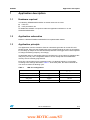
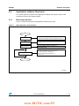
AN3996
Application Note
Adjustable LED blinking speed
using STM8SVLDISCOVERY
Application overview
This application note provides a short description of the demonstration firmware Discover
which is preprogrammed in the Flash memory of the STM8S003K3T6 microcontroller.
This demonstration firmware makes use of the STM8S basic 8-bit timer configured as a
time-base generator to change the blinking speed of LED LD1 each time the push button B1
is pressed. Once the STM8SVLDISCOVERY is powered-up through a standard USB cable
connected to the host PC, LED LD1 starts blinking slowly, meaning that the programming
has been completed successfully.
This demonstration software is available from http://www.st.com/stm8svldiscovery.
It is provided to allow you to learn, reuse and modify the application source code.
Built around the STM8S003K3T6, the STM8SVLDISCOVERY allows evaluation of the main
features of all the STM8S00xxx line MCUs.
Reference documents
October 2011
■
STM8SVLDISCOVERY user manual (UM1482).
■
STM8SVLDISCOVERY getting started (UM1480)
■
Developing and debugging your STM8S-DISCOVERY application code user manual
(UM0834).
■
STM8S003 datasheet
■
STM8S reference manual (RM0016)
Doc ID 022386 Rev 1
1/10
www.st.com
www.BDTIC.com/ST
Contents
AN3996
Contents
1
2
3
2/10
Application description . . . . . . . . . . . . . . . . . . . . . . . . . . . . . . . . . . . . . . 5
1.1
Hardware required . . . . . . . . . . . . . . . . . . . . . . . . . . . . . . . . . . . . . . . . . . . 5
1.2
Application schematics . . . . . . . . . . . . . . . . . . . . . . . . . . . . . . . . . . . . . . . . 5
1.3
Application principle . . . . . . . . . . . . . . . . . . . . . . . . . . . . . . . . . . . . . . . . . . 5
Software description . . . . . . . . . . . . . . . . . . . . . . . . . . . . . . . . . . . . . . . . . 6
2.1
STM8S standard firmware library configuration . . . . . . . . . . . . . . . . . . . . . 6
2.2
Application software flowcharts . . . . . . . . . . . . . . . . . . . . . . . . . . . . . . . . . 7
2.2.1
Main loop flowchart . . . . . . . . . . . . . . . . . . . . . . . . . . . . . . . . . . . . . . . . . 7
2.2.2
Blinking_StateMachine flowchart . . . . . . . . . . . . . . . . . . . . . . . . . . . . . . . 8
Revision history . . . . . . . . . . . . . . . . . . . . . . . . . . . . . . . . . . . . . . . . . . . . 9
Doc ID 022386 Rev 1
www.BDTIC.com/ST
AN3996
List of tables
List of tables
Table 1.
Table 2.
LED LD1 configuration . . . . . . . . . . . . . . . . . . . . . . . . . . . . . . . . . . . . . . . . . . . . . . . . . . . . . 5
Document revision history . . . . . . . . . . . . . . . . . . . . . . . . . . . . . . . . . . . . . . . . . . . . . . . . . . 9
Doc ID 022386 Rev 1
www.BDTIC.com/ST
3/10
List of figures
AN3996
List of figures
Figure 1.
Figure 2.
4/10
Main application loop flowchart . . . . . . . . . . . . . . . . . . . . . . . . . . . . . . . . . . . . . . . . . . . . . . 7
Blinking_StateMachine flowchart . . . . . . . . . . . . . . . . . . . . . . . . . . . . . . . . . . . . . . . . . . . . . 8
Doc ID 022386 Rev 1
www.BDTIC.com/ST
AN3996
Application description
1
Application description
1.1
Hardware required
The following STM8SVLDISCOVERY on-board resources are used:
●
LED, LD1
●
User push button, B1
No additional hardware is required to make this application software run on the
STM8SVLDISCOVERY.
1.2
Application schematics
Refers to UM1482 STM8SVLDISCOVERY for implementation details.
1.3
Application principle
This application uses the 8-bit timer TIM4 as a time-base generator to control LED LD1
blinking speed. Each time the STM8S Value microcontroller detects an event on push button
B1, the delay (a multiple of the TIM4 time-base) between each toggle of the LED is adjusted
to change the blinking frequency accordingly.
At application start-up, the blinking period is configured to 1 second and LD1 toggles at this
rate (every second). This configuration allows to check visually that the STM8S Flash
memory was successfully programmed.
Each time a push button event is detected on B1, LD1 blinking frequency is increased
according to the settings described in Table 1. At the third press, the LED is switched off.
You can then restart the blinking cycle.
A
Table 1.
LED LD1 configuration
Push button B1
LD1
Toggling period
At application start-up (only)
Toggles
1 sec
1st press
Toggles
200 ms
2nd press
Toggles
100 ms
3rd press
Switched off
N/A
Doc ID 022386 Rev 1
www.BDTIC.com/ST
5/10
Software description
2
AN3996
Software description
The application software uses the STM8S standard firmware library to control general
purpose functions and peripherals:
●
Clock (CLK)
The clock control enables and delivers the correct clock frequency to the CPU and
peripherals. At power-on, the master clock source is automatically selected as HSI
clock with prescaler division factor equal to 8, This setup is not changed by the
application code:
fMASTER = 2 MHz.
●
GPIOs
The GPIOs drive the MCU I/Os to interface with external hardware. They configure port
PD0 as output push-pull low to drive LED LD1, and PB7 as input floating with external
interrupt to interface with the push button B1. This interrupt is controlled by the Interrupt
Controller.
●
EXTI
The external interrupt controller is configured to control the external interrupt sensitivity
on the push-button connected to PB7. It is configured to trigger an interrupt each time a
falling edge (and only a falling edge) is detected on PB7.
●
TIM4
TIM4 is a basic 8-bit timer used as a 4 ms time base. This time base is used by the
application to control LD1 blinking speed. TIM4 is configured by the application as
follows:
2.1
–
Up Counting mode
–
TIM4_PSCR = 5 => Counting frequency is 62.5 KHz
–
Fck_cnt = fMASTER/2^PSCR[2:0]
–
TIM4_ARR = 0xFA (250 cycles)
STM8S standard firmware library configuration
The stm8s_conf.h file of the STM8S standard firmware library is used to configure the
library by enabling the peripheral functions used by the application.
The following define statements must be present:
6/10
●
#define _GPIO 1 enables GPIOs
●
#define _EXTI 1 enables EXT1
●
#define _TIM4 1 enables TIM4
Doc ID 022386 Rev 1
www.BDTIC.com/ST
AN3996
2.2
Software description
Application software flowcharts
This section gives an overview of the application software main loop as well as of the
function that controls LD1 blinking speed.
2.2.1
Main loop flowchart
Figure 1 shows the flowchart of the application software main loop.
Figure 1.
Main application loop flowchart
3TART
'0)/?#ONFIGURATION
%84)?#ONFIGURATION
4)-?#ONFIGURATION
"LINKING?3TATE-ACHINE
#ONFIGURES0$PORTASOUTPUTPUSHPULLLOW
TODRIVE,%$,$AND0"ASINPUTFLOATINGWITHINTERRUPT
#ONFIGURESEXTERNALINTERRUPTSENSISTIVITY0"TOFALLING
EDGEONLY
3TARTSTIMER4)-CONFIGUREDASTIMEBASEFOR
,%$TOGGLINGSPEED
)NCREMENTSVARIABLE"LINK3PEED MODULO
EACHTIMEAPUSHBUTTONEVENTOCCURSON"
!CCORDINGTOTHEVALUEOF"LINK3PEED
MAKESTHE,%$BLINKATDIFFERENTRATESOR
SWITCHESITOFF
%ND
AIB
Doc ID 022386 Rev 1
www.BDTIC.com/ST
7/10
Software description
2.2.2
AN3996
Blinking_StateMachine flowchart
Figure 2 shows the detailed flowchart of the Blinking_StateMachine() function part of
the main routine.
The Blinking_StateMachine() function implements the algorithm that controls the LED
blinking speed depending on the state selected by the push button.
At application start-up, the state machine is in its default state, LD1 toggles every 1 s period,
then BlinkSpeed is incremented at each push button detection. In state 1 and state 2 of
the state machine, the programmed blinking frequency is changed and LD1 is switched-off
in state 0.
LED LD1 blinking frequency is defined using the 8-bit timer TIM4 configured as a time-base
generator to assert an update interrupt every 4ms.
The toggling period depends on the value of PeriodNumber. This variable defines the
number of times the timer interrupt is to be asserted (reach overflow) before toggling the
LED LD1. As a result, LED blinking frequency can only be a multiple of 4 ms (see Table 1).
Figure 2.
Blinking_StateMachine flowchart
3TART
1# PRESSED
NO
YES
"LINK3PEED
"LINK3PEED
NO
YESCASE
,$SWITCHEDOFF
"LINK3PEED
NO
YESCASE
$ELAYMS
"LINK3PEED
NO
YESCASE
$ELAYMS
$ELAYS
,$TOGGLES
%.$
AIB
8/10
Doc ID 022386 Rev 1
www.BDTIC.com/ST
AN3996
3
Revision history
Revision history
Table 2.
Document revision history
Date
Revision
31-Oct-2010
1
Changes
Initial release.
Doc ID 022386 Rev 1
www.BDTIC.com/ST
9/10
AN3996
Please Read Carefully:
Information in this document is provided solely in connection with ST products. STMicroelectronics NV and its subsidiaries (“ST”) reserve the
right to make changes, corrections, modifications or improvements, to this document, and the products and services described herein at any
time, without notice.
All ST products are sold pursuant to ST’s terms and conditions of sale.
Purchasers are solely responsible for the choice, selection and use of the ST products and services described herein, and ST assumes no
liability whatsoever relating to the choice, selection or use of the ST products and services described herein.
No license, express or implied, by estoppel or otherwise, to any intellectual property rights is granted under this document. If any part of this
document refers to any third party products or services it shall not be deemed a license grant by ST for the use of such third party products
or services, or any intellectual property contained therein or considered as a warranty covering the use in any manner whatsoever of such
third party products or services or any intellectual property contained therein.
UNLESS OTHERWISE SET FORTH IN ST’S TERMS AND CONDITIONS OF SALE ST DISCLAIMS ANY EXPRESS OR IMPLIED
WARRANTY WITH RESPECT TO THE USE AND/OR SALE OF ST PRODUCTS INCLUDING WITHOUT LIMITATION IMPLIED
WARRANTIES OF MERCHANTABILITY, FITNESS FOR A PARTICULAR PURPOSE (AND THEIR EQUIVALENTS UNDER THE LAWS
OF ANY JURISDICTION), OR INFRINGEMENT OF ANY PATENT, COPYRIGHT OR OTHER INTELLECTUAL PROPERTY RIGHT.
UNLESS EXPRESSLY APPROVED IN WRITING BY TWO AUTHORIZED ST REPRESENTATIVES, ST PRODUCTS ARE NOT
RECOMMENDED, AUTHORIZED OR WARRANTED FOR USE IN MILITARY, AIR CRAFT, SPACE, LIFE SAVING, OR LIFE SUSTAINING
APPLICATIONS, NOR IN PRODUCTS OR SYSTEMS WHERE FAILURE OR MALFUNCTION MAY RESULT IN PERSONAL INJURY,
DEATH, OR SEVERE PROPERTY OR ENVIRONMENTAL DAMAGE. ST PRODUCTS WHICH ARE NOT SPECIFIED AS "AUTOMOTIVE
GRADE" MAY ONLY BE USED IN AUTOMOTIVE APPLICATIONS AT USER’S OWN RISK.
Resale of ST products with provisions different from the statements and/or technical features set forth in this document shall immediately void
any warranty granted by ST for the ST product or service described herein and shall not create or extend in any manner whatsoever, any
liability of ST.
ST and the ST logo are trademarks or registered trademarks of ST in various countries.
Information in this document supersedes and replaces all information previously supplied.
The ST logo is a registered trademark of STMicroelectronics. All other names are the property of their respective owners.
© 2011 STMicroelectronics - All rights reserved
STMicroelectronics group of companies
Australia - Belgium - Brazil - Canada - China - Czech Republic - Finland - France - Germany - Hong Kong - India - Israel - Italy - Japan Malaysia - Malta - Morocco - Philippines - Singapore - Spain - Sweden - Switzerland - United Kingdom - United States of America
www.st.com
10/10
Doc ID 022386 Rev 1
www.BDTIC.com/ST