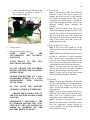
1
End of Project Documentation:
One-Armed Wijit Wheelchair
Electronic Steering Assistance
CpE 191 / EEE 193B
Professor Russell Tatro
Jonathan Evangelista
Julio McClellan
Bogdan Svityashchuk
Steven Trinh
Xiaomeng Zhang
i
Abstract— The Wijit wheelchair represents a great advancement in modern wheelchair design.
Instead of directly pushing the wheels of the chair with their hands, patients propel themselves
through the use of two levers integrated into the hub of each wheel. The use of levers to propel
the wheelchair provides patients with a better ergonomic position while still allowing for the
physical exercise associated with a manual wheelchair. It is the goal of our team to bring the
benefits of exercise and the Wijit wheelchair to patients who suffer from hemiplegia or other
debilitation that affects one side of the body and limits them to the use of one arm. Our team has
designed a wireless electronic steering assist system, which adds a limited amount of weight of
7.125 lbs. to an existing clinical wheelchair, to enable the use of the Wijit wheelchair by those
who only have the use of one arm. Our system does have its limitations such as only working on
ramps that have an incline of 3 to 5 degrees, and only operating on surfaces such as cement,
asphalt, and linoleum style floors. However with these limitations, this system provides a viable
way for patients with one usable arm to achieve neuromuscular rehabilitation and mobility.
Keyword index: Hemiplegia, Mobility, Wijit Wheelchair, Stroke, Rehabilitation
ii
Table of Contents
Abstract and Keyword Index ........................................................................................................... i
Table of Contents ............................................................................................................................ ii
List of Figures ................................................................................................................................ iii
List of Tables ...................................................................................................................................v
Introduction ......................................................................................................................................1
Societal Problem ..............................................................................................................................1
Design Idea Contract........................................................................................................................4
Funding Proposals ............................................................................................................................8
Market Review ...............................................................................................................................10
Work Breakdown Structure ...........................................................................................................13
Risk Assessment and Mitigation ....................................................................................................18
Project Tasks ..................................................................................................................................19
User Manual ...................................................................................................................................20
Design Documentation...................................................................................................................25
Hardware ........................................................................................................................................25
Software .........................................................................................................................................26
Mechanical Work ...........................................................................................................................28
Hardware Test Plan and Results ....................................................................................................31
Software Test Plan and Results......................................................................................................33
Conclusion .....................................................................................................................................34
References ......................................................................................................................................36
Glossary .........................................................................................................................................38
Appendices .....................................................................................................................................39
iii
List of Figures
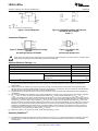
Figure 1.Hemiplegia Illustration ......................................................................................................2
Figure 2.Double Push Rim Wheelchair ...........................................................................................3
Figure 3.Invacare IVC Cycle Lever Drive .......................................................................................4
Figure 4.Meyra Wheelchair “Monodrive” .......................................................................................4
Figure 5.Wijit Lever System ............................................................................................................5
Figure 6.Steering System Block Diagram .......................................................................................5
Figure 7.Servo Connected to Gear ...................................................................................................6
Figure 8.SCI Centers in the US......................................................................................................11
Figure 9.Work Breakdown Chart ...................................................................................................14
Figure 10.Milestones Flowchart ....................................................................................................17
Figure 11.Risk Assessment Chart ..................................................................................................18
Figure 12.Screws for Lids on Lever Arm Box ..............................................................................21
Figure 13.Mounting Hole for Lever Arm ......................................................................................21
Figure 14. Port and Switch on the Rear of the Lever Arm ............................................................21
Figure 15. Zip Ties with Mounting Holes .....................................................................................22
Figure 16. Spacers for Caster Gear ................................................................................................22
Figure 17.Negative/Reverse Caster Position .................................................................................22
Figure 18.Motor Mounted with Gear .............................................................................................22
Figure 19.Motor Mounted Correctly and Aligned .........................................................................23
Figure 20.Caster Electronics Box Mounting .................................................................................23
Figure 21.Correct Caster Electronics Mounting ............................................................................23
Figure 22.Motor and Electronics Connection ................................................................................23
Figure 23.Fuse Location ................................................................................................................24
Figure 24.Power Flow During Charge ...........................................................................................25
Figure 25.Power Flow During User Operation ..............................................................................26
Figure 26.Simulation of Servo Power Circuit................................................................................26
Figure 27.Simulation of User Interface Power Circuit ..................................................................26
Figure 28.Software Code Flow Chart ............................................................................................27
Figure 29.First Iteration Assembly ................................................................................................28
Figure 30.First Iteration Exploded View .......................................................................................29
iv
Figure 31.First Iteration Bracket Left Caster Wheel .....................................................................29
Figure 32.First Iteration Bracket Right Caster Wheel ...................................................................29
Figure 33.First Iteration Bracket End Left Rod Fork ....................................................................29
Figure 34.First Iteration Lever Arm...............................................................................................29
Figure 35.First Iteration Right End Rod Fork ................................................................................30
Figure 36.Second Iteration Pre-bent Caster ...................................................................................30
Figure 37.Second Iteration Motor Mount ......................................................................................30
Figure 38.Second Iteration Motor Front End .................................................................................30
Figure 39.Second Iteration Motor Rear End ..................................................................................31
Figure 40.Third Iteration Motor Mount .........................................................................................31
Figure 41.Third Iteration Fully Assembled Drawing ....................................................................31
Figure 42.Third Iteration Caster Assembly Exploded View .........................................................31
v
List of Tables
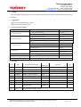
Table I. Fall 2014 Sponsor Funded Spending .................................................................................8
Table II. Spring 2015 Sponsor Funded Spending ............................................................................9
Table III. Non Sponsor Funded Spending and Grand Total for Project Spending ........................10
Table IV. Project/Feature Work Breakdown .................................................................................14
Table V. Project Hours Per Feature ...............................................................................................16
Table VI. Hardware Operation Tests .............................................................................................32
Table VII. Hardware Performance Tests .......................................................................................33
1
I. INTRODUCTION
Being able to freely move from place to place
truly makes a person feel free. Mobility is a key
aspect to a person’s rehabilitation and recovery. There are many conditions such as muscular
dystrophy, strokes, paralysis, and amputation as
well as injuries, which limit the mobility of
human beings. The standard manual wheelchair
has been a tremendous help in this issue, but
sadly disabled people with limited mobility do
not receive enough attention. Hemiplegics
belong to the group of people with limited
mobility since most have one side of the body
being very weak or totally dysfunctional. This
means that using a manual wheelchair is virtually
impossible for hemiplegic patients.
Not being able to move from place to place
easily is probably one of the hardest thoughts to
bear. When a person is in a place of
discouragement and cannot see an alternative to
the problems, improvements of the damaged part
of the body seem unlikely since in this emotional
state a person is not motivated to exercise or seek
improvement. On the other hand, a disabled
person that is able to move around the house or
outside and be independent can have more hope
in improvement and thus better chances of some
degree of recovery.
Of course an electric wheelchair is a solution to
the mobility problem of disabled people since
people who have at least one healthy arm can
operate it, but this mobility solution lacks many
aspects in the improvement of the disabled
person. An electric wheelchair helps these
persons be more independent, but often takes
away the opportunity to be at least a little
physically active and gain back strength in half
of their body. This of course can have many
negative consequences for the patients, and limit
the recovery if it is possible.
The Wijit Wheelchair is a better alternative to the
electric wheelchair since in order for a person to
move to certain destinations, the person needs to
do a little more than just pushing an input
control. The Wijit uses two levers that the person
moves back and forth to drive, thus providing a
wonderful opportunity for exercise and
neuromuscular
rehabilitation.
The
same
technique can be applied to help patients who
have only one healthy arm such as hemiplegics.
A Wijit designed for use with one arm can be
very beneficial for these kinds of disabled
people.
After months of design and testing a modular
wireless electronic steering assist system was
created to work on top of an existing Wijit
Wheelchair. By adding only 7.125 lbs. of
additional electronics to a clinical wheelchair
equipped with Wijit lever arms, a user who only
has one healthy arm can both propel forward and
backward, and turn left and right. This is
achieved with an input device, a joystick,
mounted to the lever arm that wirelessly controls
a high torque servomotor mounted to the front
caster. A user is able to use this system on a
number of surfaces that include concrete, asphalt,
and vinyl linoleum style floors. However, they
do need to be careful using wheelchair ramps
because only using one arm will not provide
enough power to get up ramps that have a 6
degree incline or greater. With this system being
modular, a patient with either a healthy left or
right arm is able to achieve mobility and
neuromuscular rehabilitation by simply moving
the electronics around the wheelchair.
II. SOCIETAL PROBLEM
A. Hemiplegia and Hemiparesis
Every year, 610,000 people experience their first
stroke, and 185,000 more have a recurrent stroke
attack [1]. Hemiplegia commonly occurs after a
stroke. Hemiplegia is the commonest form of
paralysis, involving arm, leg and sometimes the
face on one side of the body [2]. In effect, in
many cases the disabled person is not able to feel
any pain in the paralyzed side of the body.
Hemiparesis is very similar to hemiplegia and the
name is often used interchangeably, but it is
more of a partial paralysis or weakening of the
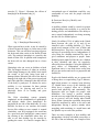
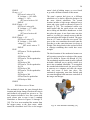
2
muscles [3]. Figure 1 illustrates the effects of
hemiplegia on the human body [4].
conventional type of wheelchair would be very
comfortable or even safe for people with this
disability.
B. Emotional Benefits of Mobility and
Independence
A mobility solution would be crucial for people
with hemiplegia since mobility is so vital to the
healing process, and rehabilitation. The ability to
move around independently can bring meaning
into the life of a disabled person.
Fig. 1. Hemiplegia Illustration [4]
When a person has a stroke, it may be caused by
a blood clot near the brain, or a burst artery in the
brain area. This cuts off blood carrying oxygen to
the brain and often results in the death of brain
cells. The paralysis hemiplegia is caused by this
death of brain cells. In patients with hemiparesis
the brain cells are also damaged, but to a lesser
extent.
Hemiplegia also can occur in children at birth.
This can happen because of either an accident,
which brings damage to the child’s brain inside the womb, or the baby being born with a
damaged brain. When the left side of the brain is
damaged, the right side of the person is paralyzed
and if the right side is damaged, then the left side
of the body is paralyzed. A solution for active
mobility is very important for these patients
because they are growing and need to be
physically active to be healthy and grow
normally.
The Wijit wheelchair system primarily
emphasizes on the rehabilitation of quadriplegic
and diplegic adults. Since hemiplegics are
paralyzed on one side of the adult body, it is very
difficult for them to use crutches and similar
devices like walkers to move around. A manual
wheelchair, even Wijit equipped, also would not
be a good tool since hemiplegics cannot control
the steering of the wheelchair unless they are
able to use their healthy leg for steering by
guiding the caster. It is hard to imagine that a
Nearly 10 million (5.2%) of adults in the United
States between the ages of 18 and 64 are
classified with a walking disability [1]. These
people need someone to take care of them and
take them places. They have a need for a healthy
and easy to use mobility device. Independence is
a key factor for a healthy emotional life, since it
gives confidence and purpose to people. Some
disabled people might feel like they are a burden
to their caretakers and thus, are negatively
affected by these thoughts. Giving the disabled a
good choice of independent mobility is
significant since it can make them realize that
they are not useless and can live a purposeful and
fruitful life.
People with limited mobility are at a greater risk
of being obese or experiencing Type 2 diabetes,
high blood pressure or coronary heart diseases
[5]. Health issues on top of the disability will
surely have a negative effect on a disabled
person both physically and emotionally. The
depression rates are higher for people with
disabilities. Not having a positive attitude
towards recovery might lead the person to giving
up on recovery and risk having other health
issues. When a person has a problem, that person
should be motivated by others to be active and
independent. Having a positive attitude when
struggling with something is a much better and
less painful way to resolve the problem.
There are many examples of how mobility and
independence can help a disabled person have a
life full of fun and meaning. An example of this
3
is an Australian born man, Nick Vujicic. Nick
was born without legs and arms, but that did not
stop him from living to the fullest [6]. Of course
he had times of depression, but his faith and the
ability to do as much things as he could made his
life fun and active. Not having any limbs did not
stop Nick from learning to swim, play golf, drive
an electric wheelchair, get married and have a
child, and perform many other activities. The
example of this man truly shows that
independence and mobility can give hope to the
disabled and help in their recovery.
In his case, Nick uses an electric wheelchair for
mobility, but that alone would not let him be who
he is today. Apart from moving around on the
wheelchair he is involved in many tough
activities, which use his whole body, and provide
a great workout. An electric wheelchair can solve
the mobility problem of hemiplegic people, but it
is not hard to imagine that not many disabled
people have so much motivation to get out of the
wheelchair and be involved in other physical
activities. That is why it would be great to have a
mobility device that provides some physical
activity to hemiplegics without having to get out
of a wheelchair.
and endurance, proper biomechanics, and the
uses of suitable wheelchairs have been
highlighted as important factors affecting
mobility performance [9].
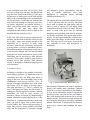
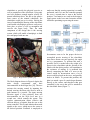
The double push rim wheelchair shown in Figure
2 can be operated with one arm [10]. One push
rim is used to operate the right wheel, and the
other is used to operate the left wheel being
connected to the axle of the left wheel. The user
needs to push both push rims for forward
propulsion and individual push rims for steering.
As already mentioned, this motion may lead to
injuries, but the biggest downside is that the user
needs to provide energy to both wheels with one
arm. This may lead to even more strain on the
arm, especially in users with hemiparesis or
hemiplegia.
C. Solution Choices
In finding a solution to the problem of mobility
for hemiplegic patients it is important to have a
wheelchair that does not bring more harm or
injury to the user, but contrastingly helps in the
rehabilitation and recovery process. Over 50
percent of manual wheelchair users with spinal
cord injury (SCI) are likely to develop upperlimb pain and injury [7]. This is a statistic for
users with spinal cord injury, but the motion of
pushing the wheels required to operate a manual
wheelchair can lead to stress injuries of
shoulders, elbows, and wrists [8]. Maneuvering a
manual wheelchair requires applying force to the
hand rims in a repetitive motion that, in the long
term, can lead to upper limb overuse injuries.
Several studies have shown high prevalence of
upper limb injuries among manual wheelchair
users and the importance of muscular strength
Fig. 2. Double Push Rim Wheelchair [10]
Since manual wheelchairs can lead to injuries in
people with healthy arms, hemiplegic patients
would be even more vulnerable to arm damage.
A lever driven wheelchair would be optimal for
hemiplegic users who can use only one hand or
have weak muscles and need exercise to prevent
muscle atrophy. This kind of system protects the
user from pain and injuries caused by traditional
manual wheelchairs. It also provides the patient a
great way to exercise and strengthen the upper
body.
4
There are a few wheelchairs that are currently
available in the market with single lever actuated
systems. However, most of these options are
permanently attached to the wheelchair when it is
ordered. This type of attachment may be
undesirable to some because as the rehabilitation
and recovery process moves along they may not
need it anymore. If that were the case, the user
would have to buy a brand new wheelchair to
replace the one with the permanently attached
system. A more modular design is desirable in
many cases for transportation and for storage.
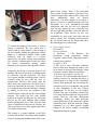
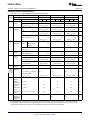
The wheelchair shown in Figure 3 is one of the
available lever actuated one-arm wheelchairs
[11]. It is the Invacare IVC CLD (Cyclical Lever
Drive), which includes a front-caster steering
mechanism, simple rowing motion design and
adjustability in height and stroke length of the
lever. In this design, twisting the lever clockwise
for right turns and counter clockwise for left
turns allows steering. A video of a patient with a
weak arm operating this wheelchair revealed that
the motions of moving the arm forwards and
backwards for propulsion and the twisting
motion for steering can conflict with each other
in users with arm weakness. The user had a
difficult time going straight and avoiding
bumping into walls. Thus, this design might be
uncomfortable for users with arm weakness.
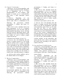
Another solution having a very similar concept is
the Meyra Monodrive Wheelchair shown in
Figure 4 [12]. In this wheelchair propulsion and
steering are accomplished in the same way, but
braking is accomplished by moving the lever to
the extreme forward or backward position [12].
This braking approach would possibly work for
many people who have at least one healthy arm,
but would not be useful for people who have a
very weak arm and can not move it all the way
back to break.
Fig. 4. Meyra Wheelchair “Monodrive” [12]
The presented solution choices address the need
for a non-electric wheelchair that provides a way
of exercise and mobility for people with only one
healthy arm, but the steering systems might be
hard to use. To steer the presented wheelchairs,
the user has to turn the lever left or right while
also pushing it back and forth for propulsion.
This motion might be complicated for people
who have a weakened arm and can make the
wheelchair difficult to control.
III. DESIGN IDEA CONTRACT
Fig. 3. Invacare IVC Cycle Lever Drive [11]
There are two main goals that our design idea
plans to accomplish in one product: mobility for
hemiplegics, and a way of exercise and
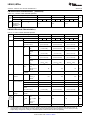
rehabilitation. The Wijit lever system shown in
Figure 5 will be used on one of the wheels of a
5
wheelchair to provide the physical exercise as
well as propulsion of the wheelchair. Using only
one lever produces enough angular velocity for
normal wheelchair drive, but due to the passive
front casters of the manual wheelchair, the
wheelchair would just go in circles. Solving the
issue of controlling the steering of the wheelchair
would enable a hemiplegic person to easily move
from place to place as well as strengthen and
exercise the upper body. Thus, the main
component of our design idea is the steering
system, which will enable a hemiplegic to both
steer and propel with one arm.
make sure that the steering operation is actually
performed, and if it is not, the controller prompts
the servo a second time to turn to the desired
position. Two batteries are used in the design to
supply power to the lever arm electronics and the
electronics pertaining to powering the motor.
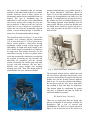
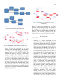
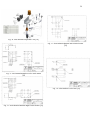
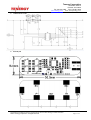
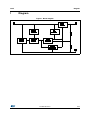
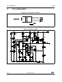
Fig. 6. Steering System Block Diagram [14]
Fig. 5. Wijit Lever System [13]
The block diagram shown in Figure 6 depicts the
main
design
components
and
their
interconnection in the design idea [14]. The user
activates the steering control by inputting the
desired steering direction with devices such as
push buttons or a joystick. The input steering
direction signal is sent wirelessly from one
microcontroller on the Wijit lever arm to a
second one, which controls the motor. This
wireless communication allows effective and
efficient delivery of signals from the user to the
motor controller. This second Arduino then sends
signals to the servo, which moves the caster to
the desired position. Feedback is employed to
Servomotors seem to be the proper devices to
accomplish precise steering of the wheelchair
since these motors can turn precisely the angle
set by a programmer. To perform this task, a
powerful servo is needed since the weight of a
person in the wheelchair and the friction of the
wheels with the driving surface will contribute to
the resistance of turning. It is predicted that
directly connecting the shaft of a servo to the
casters would be inconvenient since a lot of
stress would be placed on the servo, and possibly
lead to its failure. To prevent this problem, the
plan is to attach a gear of a much larger diameter
directly to the casters, and then have that gear
controlled by the servo that will be attached to
the wheelchair frame (Figure 7).
6
Fig. 7. Servo Connected to Gear [13]
To control the turning of the servos, a wireless
system is proposed. The user would have a
control such as a push button, or the twisting of
the lever handle sending the appropriate control
signal to a transmitter module, which would
wirelessly send out signals to a receiver
connected to the motor control microcontroller.
The wireless communication would also allow
for various customizable steering control
methods such as mouth or body position control..
Completing the design to meet the goals of safe
mobility and exercise would be a braking system
to effectively stop the wheelchair. The Wijit
lever system contains a braking system, which is
activated when the user pulls the lever in,
towards him. However, this would cause the
other wheel not connected to the Wijit lever to
spin freely and make the user spin. To avoid this,
it is proposed that when the braking is initiated
by pulling in the lever, the position of the
controlled front caster will stay in a fixed straight
position. The design has the caster default
position as straight, and thus the user would not
need to do any extra thinking when braking
besides pulling in the lever. Also, since the front
caster is controlled by the motor at all times, the
chair would not swerve when applying the brakes
even while making turns.
This design is a unique addition to the Wijit
system because there is no product that combines
wireless steering and braking control with a one-
armed Wijit system. There is the two-armed
Wijit system, but that requires a person to have
control of both of their arms to drive, brake, and
steer.
Additionally,
there
are
electric
wheelchairs, but those designs do not allow a
person to exercise or perform therapy with arm
movements of a lever. Mechanical one-hand
wheelchairs that also use the lever approach
exist, but they require the user to turn the lever
left and right while pushing it forward and back
for propulsion. These devices are not very
comfortable for users with weak arms, and can
even be unsafe. The following sections present
the five main features in the design and reflect
the planning process of the design.
A. Power Supply System
LiPo Battery
Power regulation
1) Hardware: 2 LiPo Batteries; the
wheelchair; wiring components; voltage
regulator, various circuit components such as
resistors and capacitors
2) Software: N/A
3) Who will do what: The three members,
who are Electrical Engineering majors, will
be in control of wiring of the hardware, along
with power control and power regulation.
4) Estimated total number of hours: 40
5) Outcome: We will determine this feature is
working correctly be ensuring that there is
efficient power to keep all the wheelchair
features fully functional, and can sustain the
wheelchair user for a reasonable long period
of time, depending on the user, without
interruptions. To do this we will conduct
multiple tests once everything is hooked up
to see how long these batteries can power this
system. Then we will make adjustments
accordingly. Ideally, the entire powering
system should survive the failure test without
significant errors. With the inclusion voltage
regulation, we can then provide enough
voltage to the devices without overloading
them and shorting the system.
7
B. Controls / User Interface
1) Hardware: Up to 2 microcontrollers, such
as the Arduino, Parallax Propeller, Raspberry
Pi, or Beaglebone; Up to 2 Xbee
shields/modules or wi-fi dongles; push
buttons or switch; up to 2 servos/motors;
Wijit arms; 2 front wheelchair casters;
battery
2) Software:
Depending
on
the
microcontroller platform the software that
will be used will be a combination of the
following:
the
open-source
Arduino
environment, C, Python, and Linux (i.e.
Raspbian).
3) Who will do what: Jonathan will be the
main programmer, as he is a Computer
Engineering major, and will deal with the
microcontroller interfacing. Steven will help
with the electrical engineering aspects, such
as making sure the correct amount of voltage
and current are used to achieve proper
controls for the user.
4) Estimated total number of hours: 50
5) Outcome: We will determine that this
feature is working correctly by first testing
that the controls work to turn on simple
LEDs or turn the servo, without connecting
to the wheelchair in the lab with physical
wires. Then we will attach these components,
with the sensors after sensor testing to the
wheelchair with the Wijit arm and do further
testing such as making sure the buttons or
switch work. After this testing is complete,
we will test with wireless modules such as
the Arduino Xbee or wi-fi dongles.
C. Wireless Communication
1) Hardware: up to 2 microcontrollers, such
as the Arduino, Parallax Propeller, Raspberry
Pi, or Beaglebone; 2 Xbee shields/modules or
wi-fi dongles; push buttons or switch; up to 2
servos/motors; Wijit arm; 2 front wheelchair
casters; battery
2)
Software:
Depending
on
the
microcontroller platform the software that
will be used will be a combination of the
following:
the
open-source
Arduino
environment, C, Python, and Linux (i.e.
Raspbian).
3) Who will do what: Jonathan will be the
main programmer, as he is a Computer
Engineering major, and will deal with the
microcontroller interfacing. Steven will help
with the electrical engineering aspects, such
as making sure the correct amount of voltage
and current are used to achieve proper
controls for the user.
4) Estimated total number of hours: 100
5) Outcome: We will determine that this
feature is working correctly by first testing
that we are able to communicate with both
microcontrollers wired. Then we will make
sure that the Xbee or wi-fi modules
themselves work to transmit signals from the
arm to the servos. We will then perform more
tests of the wireless communication on
breadboards before actually attaching them to
the wheelchair. After this testing is complete,
we will test the microcontrollers with the
wireless modules, on the wheelchair, and
ensure that the user is able to turn and that
the wheels turn according to the switch or
buttons in the arm.
D. Servo and Sensor Feedback System
1) Hardware: 2 microcontrollers, such as the
Arduino, Parallax Propeller, Raspberry Pi, or
Beaglebone; 2 Xbee shields/modules or wi-fi
dongles; three position switch;up to 2
servos/motors; Wijit arm; 2 front wheelchair
casters; battery
2)
Software:
Depending
on
the
microcontroller platform the software that
will be used will be a combination of the
following:
the
open-source
Arduino
environment, C, Python, and Linux (i.e.
Raspbian).
3) Who will do what: Jonathan will be the
main programmer, as he is a Computer
Engineering major, and will deal with the
microcontroller interfacing. Steven, Bogdan,
and Christina will help with the electrical
engineering aspects, such as making sure the
correct amount of voltage and current are
used to achieve proper controls for the user.
8
4) Estimated total number of hours: 70
5) Outcome: We will determine that feature is
working correctly by first testing that the
controls work to turn the servos, without
connecting to the wheelchair, in the lab with
physical wires. Then we will connect the
ping sensors and test them to see if they will
provide feedback on which way and whether
or not the servos have turned. After, we will
attach these components to the wheelchair
with the Wijit arm and do further testing such
as making sure the buttons or switch work
still wired. After this testing is complete, we
will test with wireless modules such as the
Arduino Xbee or wi-fi dongles.
E. Free Wheel Mode (Mechanical)
1) Hardware: Front casters; up to 2
servos/motors, mounting apparatuses, quick
release buttons, and solenoid
2) Software: N/A
3) Who will do what: The mechanical
engineering senior project team, Michael
Peri, Sophaly (Paul) Hiep, and Simi
Randhawa, with their advisor Professor Vogt
will be handling this aspect of the project.
Then they will design a mounting apparatus
that can be used with the specific motor
chosen and our microcontrollers and have
quick release buttons to remove whatever
linkage there may be from the motor to the
front caster to allow the wheel to rotate
freely. If time allows Bogdan and Steven will
work on setting up a solenoid with the
buttons so that the wheels can be released
electronically without having to bend down
and release the buttons on the mounting
apparatus. Julio and Steven will also take part
in this feature.
4) Estimated total number of hours: 50
5) Outcome: We will determine that this
feature is working correctly by collaborating
with mechanical engineering professors and
students. They will help us in figuring out
how to incorporate release buttons into the
design of the mounting apparatus. Once we
have the okay from them, then we will
integrate these aspects into our system. When
the mounting apparatus is connected to our
system we will perform tests with various
users, of varying weight, to ensure proper
operation and release when the buttons are
activated. We will also test, if time allows for
the design of an electronic release, that there
is enough power going to the solenoids and
button to allow for the release.
IV. FUNDING PROPOSALS
Funding for this project was broken up into two
parts: electronics and mechanical. The project
was funded by our sponsor Brian Watwood, the
inventor of the Wijit System. Brian Watwood
had given one member of the group the sole
responsibility of buying items, Steven Trinh.
There were definitely some exceptions to this
however as we progressed throughout the
semester. One member of the group had shorted
a LiPo battery and had to purchase another one
right before an expo, and thus had to purchase it
with their money. There are various
miscellaneous parts that had been bought by
another team member that were thought to be
useful but ended up not, such as some extra
charging protection circuits, bolts, and spacers.
The mechanical team had outsourced some of
their work to a third party company due to a
special type of aluminum which is hard to bend,
and Sacramento State University did not have the
tools necessary to bend in house. The following
tables summarize all the costs of this project.
Table I.
Fall 2014 Sponsor Funded Spending [14]
Items Bought
Quantity Price Total
Parallax Ping ultrasonic Range
Sensor 28015
2
$24.99 $49.98
American Weigh Scale
American Weigh H-110
Digital Hanging Scale, 110 X
0.05-Pounds
1
$17.28 $17.28
ArcBotics Metal Gear Micro
Servo with Analog Feedback
1
$13.99 $13.99
Ventisonic® KY-008 Laser
Transmitter Module for
Arduino AVR PIC
2
$6.99 $13.98
9
Items Bought
Quantity
Price
Total
Arduino Xbee Shield
1
$19.95 $19.95
Xbee Explorer Dongle
2
$29.95 $59.90
Xbee 1mW Chip Antenna
2
$29.95 $59.90
SainSmart MEGA + SainSmart
Sensor Shield V4 + SainSmart
XBee Shield for Arduino UNO
MEGA
1
$29.99 $29.99
Super-Swivel Ball Joint Rod
End, 3/8”-24 Right-Hand Male
Thread, 3/8” ID, 1-3/8” L
Thread
2
Aluminum Flange-Mount
Housing for Linear Bearing,
for 1-1/8” Bearing OD
1
$31.28 $31.28
Perma-Lube Steel Ball Bearing
— ABEC-1, Double Sealed,
No. R8 for 1/2” Shaft
Diameter, 1-1/8” OD
1
$13.49 $13.49
Recessed Push-Button QuickRelease Pin, All Stainless
Steel, 3/8” Diameter, 1-1/2”
Usable Length
2
Multipurpose 6061 Aluminum,
90 Degree Angle, 3/8” Thick,
3” X 4” Legs, 2’ Long
1
Alloy 932 (SAE 660) Bronze
Sleeve Bearing, for 1/2” Shaft
Diameter, 3/4” OD, 3” Length
1
Multipurpose 6061 Aluminum,
Rectangular Bar, 1/2” X 1”, 1’
Long
1
Multipurpose 6061 Aluminum,
1” Thick, 1-1/2” Width, 1’
Length
1
Heavy Duty Aluminum
Clamp-on Framing Fitting,
Add-on Flange, Fits 1” OD
Tube
2
McMasterCarr Shipping
1
Bourns Encoders
1
Mouser Electronics Shipping
1
$32.99 $32.99
Shaft Extender
1
$41.41 $41.41
Designatronics Inc. Shipping
1
$79.50 $79.50
$9.92 $19.84
$33.23 $66.46
$48.57 $48.57
$11.17 $11.17
$4.99
$4.99
$13.15 $13.15
$40.48 $80.96
$10.74 $10.74
$6.69
$6.69
Total:
$726.21
Table II.
Spring 2015 Sponsor Funded Spending [14]
Items Bought
Quantity Price
Total
Invenscience i00600 Torxis
Servo 1600 on.in. 1.5 sec/90
deg
2 $289.00 $578.00
Pololu Shipping
1 $20.95 $20.95
Amico 4 pcs AC 125V 6A
3Pin SPDT on/off/on 3
Position mini Toggle Switch
1
$2.78
$2.78
2-Axis Joystick
1
$6.95
$6.95
Adafruit Shipping
1
$9.18
$9.18
Bluecell 2 pcs Black Medium
Size Lipo Battery Guard
Sleeve/Bag for Charge &
Storage
1 $15.23 $15.23
HATCHBOX 1.75mm
Green/Black PLA 3D Printer
Filament — 1kg Spool (2.2
lbs) — Dimensional
Accuracy +/- 0.05mm
2 $21.98 $43.96
Universal AC Adapter 15V
16V 18V 18.5V 19V 19.5V
20V 22V 24V 70W
1 $13.80 $13.80
Battery Management
Lithium-Ion Battery Charger
Controller 8-SOIC -20 to 85
(1 piece)
1
$6.70
$6.70
Battery Management
Lithium-Ion Battery Charger
Controller 8-SOIC -20 to 85
1
$8.16
$8.16
5 pcs SYB-170 Color Board
Mini Small Breadboard
1
$6.81
$6.81
URBEST 5 Pcs AC 125V 6A
ON/OFF/ON 3 Position
SPDT 3 Pins Toggle Switch
with Waterproof Boot
1
$5.99
$5.99
Venom 25C 4S 5000mAh
14.8 LiPO Battery
1 $78.94 $78.94
Amico 4 Pcs AC 125V 6A 3
Pin SPDT On/Off/On 3
Position Mini Toggle Switch
Blue
1
$2.78
$2.78
Total:
$617.86
10
Table III.
Non-Sponsor Funded Spending and Grand Total
for Project Spending [14]
Items Bought
Quantity Price
Total
Replacement
LiPo battery
1
$100.00
$100.00
Misc. Electronics
1
$50.00
$50.00
Total:
$150.00
Project
Spending
Grand Total
$1,494.07
V. MARKET R EVIEW
A. Overview
Mobility and independence are crucial factors for
wheelchair users bringing them hope in
rehabilitation and emotional health. Harry
Laswell, the former CEO of Wijit Inc, estimated
in 2012 that 10 million people in the developed
world use or need wheelchairs including 3.5
million in the U.S. [15]. This number is expected
to grow due to the aging of baby boomers and
increase in injured veterans due to worldwide
conflicts. Unfortunately the standard manual
wheelchair has in a way become a symbol of
disability. Since there are many wheelchair users,
the wheelchair should not be just an aid or a
piece of equipment for transporting a disabled
person, but become a symbol of independence
and rehabilitation.
The Wijit wheelchair driving and braking system
has revolutionized the standard manual
wheelchair into a symbol of independence,
rehabilitation, and exercise. The two-lever
propulsion eliminates the need of touching the
pushrims and thus helps prevent wrist and
shoulder joint injuries allowing the user to easily
move forwards and back. The lever arm
decreases the force that the user has to apply for
propulsion and makes wheelchair use easy for
people with weak arm muscles. The ease of use
and healthy exercise associated with Wijit
operation can be a significant motivating factor
in the rehabilitation of disabled people.
Specific groups of disabled people who have
only one arm for wheelchair operation are
hemiplegics. A few solutions have been
developed to assist these people with specialized
wheelchairs, but the solutions often fall short of
properly addressing the problem of mobility and
rehabilitation. Many types of individuals can use
our one-armed Wijit wheelchair electronic
steering assistance system over a wide range of
disabilities. Including both young and old, these
disabilities could be diplegia, hemiplegia,
paraplegia, and quadriplegia. However, we will
be narrowing the market of our product towards
those who suffer from hemiplegia, mainly those
who are over 50 years of age or are military
veterans. It will also be marketed to those that
will be prescribing the wheelchairs and assisting
in the rehabilitation process such as physical
therapists, occupational therapists, and family
physicians.
B. Target Customers
1) 50+ Adults/Geriatrics
There are many in the population of the
United States that can be categorized as over
the age of 50 and geriatrics. The population
of the United States is aging and many of
them have existing disabilities or will
experience a disability as they age.
According to a current population report for
2010, in the age range of 45-54 19.7% have
some type of disability, and the number
increases all the way up to 70.5% for those
80 and above [16]. The number of the U.S.
population, according to 2010 census data,
that use a wheelchair is 3.3 million [17]. So
not only are there older people with
disabilities, but there is a large number of
wheelchair users as well, which includes this
older portion of our population. Wheelchairs
can provide mobility and a sense of
independence for those over 50, and help
11
them live and rehabilitate with their disability
or disease.
One of the diseases that can affect adults over
50 is cerebral palsy. It is also possible for an
adult to grow up with the disease and have to
overcome the challenges that come with
aging with cerebral palsy. With cerebral
palsy a person could also suffer from
hemiplegia because of the damage to the
brain’s motor centers. According to registered nurse Diane Walker, “25% of people with cerebral palsy who walk as
children lose that ability as they get older,
either because of pain, or because using a
wheelchair
or
scooter
become
easier”[18]. Another illness that affects the
older population is strokes. Hemiplegia
commonly occurs after stroke and it is the
most common form of paralysis, involving
arm, leg, and sometimes the face on one side
of the body [2]. Both cerebral palsy and
strokes can lead to an older adult
experiencing hemiplegia, but our system can
help alleviate some of the side effects of
these conditions.
b. SCI—SCI is also known as the Spinal
Cord Injury. A person who is suffering from
SCI usually has limited mobility, since the
spinal cord plays a big role in the human
nervous system. Every year, more than
10,000 people in the U.S. sustain a spinal
cord injury (SCI) [21].
c. VA’s SCI centers: There are a total of 25
Spinal Cord Injury Centers (SCI Centers) that
are located around the country. They provide
excellent treatment for patients who suffer
from spinal cord injuries. Our industry
sponsor Brian Watwood informed us that the
VA’a SCI network is coordinated by hub centers with satellite clinics. One of the main
hubs, Seattle SCI center, has over 1,000 SCI
patients receiving their medical treatment.
There are also a handful of processing centers
that the V.A. employs to treat and reintroduce
wounded veterans to society, such as Walter
Reed Center in Washington DC, San Antonio
Center in Texas, and Long Beach, CA. These
are all large medical centers catering to the
rehabilitation of badly injured military
personnel.
Our Wijit system can help those adults
become mobile and achieve better well-being
through neuromuscular rehabilitation, by
having the Wijit lever arms to manually
propel and the help of our electronic steering
control. They will be able to help rehabilitate
both their bodies and minds with this system.
Without a system like ours adults would
experience a “severity of disease and reduced
overall health and well-being” [19].
Fig. 8. SCI Centers in the US [22]
2) Military Veterans
a. VA—Also known as the US Department
of Veteran Affair. It is a government-owned
program that works specifically for the
benefit of US veterans. VA operates the
nation’s largest integrated health care system, with more than 1,700 hospitals, clinics,
community living centers, domiciliaries,
readjustment counseling centers, and other
facilities [20].
C. Medical Providers / Potential Partners
1) PT and OT
APTA---A physical therapist is a licensed
professional that will help people with
mobility limitations [23]. They can examine
and evaluate a patient, based on their
condition and have the power to recommend
their patients with necessary devices such as
a shower chair, a walking cane, wheelchair,
12
etc. According to APTA (American Physical
Therapist Association), PTs examine each
individual and develop a plan using treatment
techniques to promote the ability to move,
reduce pain, restore function, and prevent
disability [24].
AOTA—An occupational therapist provides
assistance for people with limited mobility.
They assist the patients with personal care in
order to help them achieve daily activities.
Based on the information on the AOTA’s website, “Occupational therapy services may include comprehensive evaluations of the
client’s home and other environments,
recommendations for adaptive equipment and
training in its use” [25]. Both of the PTs and Ots provide health care
in a large variety of setting, such as hospitals,
private medical centers, clinics, school and
sports facilities, etc. If the Wijit product can
gain recognition through the APTA and
AOTA, it is going to promote a large number
of sales in the future, and therefore generate
very positive revenue.
2) Family Physicians
Family physicians can write prescriptions for
wheelchair evaluations to those patients that
they deem necessary so that they can obtain
the proper wheelchair. That is one of the
main reasons why the category of these
physicians should be included in the market
for our system. By marketing this system to
family physicians we can show them another
option for their patients that suffer from
numerous ailments that lead to hemiplegia.
To obtain a prescription from physicians, the
physician has to be sure that the Wijit one
arm wheelchair is very necessary for the well
being of a patient. Thus it is important to
show family physicians the change a Wijit
wheelchair can make in a person’s life, especially for a person who is paralyzed on
one side of the body.
Family physicians usually know their patients
pretty well and are involved in many aspects
of a person’s health. They often can have
close relationships with the patients since
they study the patient for years and help out
when various medical issues arise. This
means that these people are well acquainted
with the needs of their patients and the close
relationships with patients help provide the
patient with the necessary equipment for
treatment. This group of people is very
important in the path of providing quality
wheelchairs for hemiplegic patients and
should be informed of the benefits of the
Wijit one arm wheelchair.
3) Physiology (rehab)
Rehabilitation is often one of the first steps
on the road to recovery for post stroke
patients. Often many skills have to be
relearned. Coordination of movements
involving the use of the arms or legs is
generally impaired due to the brain damage
suffered during a stroke. Rehabilitation may
also involve teaching patients how to learn
new skills or use new tools as is the case with
patients suffering from post stroke paralysis
[26]. Paralysis such as hemiplegia is one of
the many different forms of paralysis that
may affect post stroke patients.
Rehabilitation providers can be both in home
and out patient. These providers make up a
large portion of our market focus. The focus
of rehabilitation on exercise and acquiring
the skills needed to promote the best possible
recovery fall right inline with the sentiment
behind the Wijit wheelchair design. It is
difficult to get exact data on just how many
post stroke rehabilitation providers there are
in the state of California let alone the
country, but the number is high based on a
sample size such as the Sacramento area. We
found there to be about 85 listings for stroke
or physical rehabilitation in the Sacramento
area (this excluded personal physicians and
addiction services) [27].
13
The benefit of focusing on rehabilitation
providers can be two fold. Since a provider
will most likely have multiple patients
throughout a year, the cost of a Wijit
wheelchair designed for post stroke
hemiplegia can be spread and perhaps better
reach patients in need. The other benefit is
product exposure. There are roughly 460,000
people a year in the United States that require
post stroke rehabilitation [26]. Those that are
faced with the challenge of recovering from a
stroke may very well get their first exposure
to the tools they will need from a
rehabilitation provider. Since rehabilitation
providers are crucial to the recovery of stroke
patients, they are also a crucial market group
for the steering assisted Wijit wheelchair.
D. Summary
People can be stuck in a wheelchair for
numerous reasons. In the U.S. alone there are
about 3 million wheelchair users, but it is not
hard to imagine that many more either could not
get access to one, or just gave up on using a
wheelchair. Mobility and independence are
crucial factors for wheelchair users bringing
them hope in rehabilitation and emotional health.
It is great when a person stops using a
wheelchair, but only if the person does not need
it anymore. Many people can give up on
wheelchairs thinking that they can never
improve, and do not have the motivation to work
on rehabilitation and staying positive. This is
why team Tijiw designing the one arm Wijit
wheelchair with electric steering hopes to make
available a device that does not let a person stop
using the wheelchair until it has helped them
rehabilitate, possibly relearn basic motor skill
functions after a stroke, and keep muscles in tone
and far from atrophying.
There are a number of products on the market
that try to address this problem but fail to make it
easier on the patient. With our product, we try to
address this issue of one arm rehabilitation with
the assistance of the Wijit Driving and Braking
System. The Wijit wheelchair has proven to be
efficient, easy to transport, comfortable, and
helpful in the regeneration of neuromuscular
connections. People that use the Wijit praise it
for the mobility they attain with it and the
exercise that they get while driving it around.
Shoulder joint and wrist injuries, which resulted
from standard manual wheelchair use, are not a
problem with the Wijit. Incorporating electric
steering into the Wijit for one-arm propulsion,
the team hopes to help in the rehabilitation of
hemiplegics. There are many cases of
hemiplegics rehabilitating to the point where
they can again walk and perform basic tasks with
their paralyzed side. The one arm Wijit design
can be very beneficial in this rehabilitation
process.
The product being designed is at first intended
for use in a clinical setting for hemiplegic
rehabilitation. The target patients for this
wheelchair are people aged 50 and above as well
as veterans. The geriatric population needs
rehabilitation and a comfortable mobility
solution since exercise is very important at that
age and the risk of getting more injuries is pretty
high. War Veterans definitely deserve only the
best to help them adapt back to normal life and
change the focus from their injuries to the
opportunities ahead of them due to a great
wheelchair. To be able to reach out to these
people who desperately need an effective
mobility device, it is important to demonstrate
the benefits of the one arm Wijit to VA clinics,
Physical
Therapists,
Family
Physicians,
Occupational Therapists, and rehabilitation
centers.
VI. WORK BREAKDOWN STRUCTURE
The work required to complete this project is
split up into the main features and the tasks that
needed to be accomplished for proper
implementation of those features. A clear map of
the project tasks and procedures is essential to
good planning of the project. A chart showing
the project from a top level and going into detail
with a downward flow is a great tool for project
planning and progress evaluation. The team used
14
this method in both semesters. The Work
Breakdown Chart for our project is shown in
Figure 9 [14]. This chart reflects the basic
structure developed in the first semester, and is
updated with the tasks for both semesters.
The firs semester design phase consisted of
completing a laboratory prototype, while the goal
of the second semester was the completion of a
functional deployable prototype. Throughout the
design of the project several design changes were
made to fulfil the project requirements. For
example, the team used a five phase stepper
motor in the first semester for the task of steering
the casters. This device had to be changed since
it was relatively heavy and did not provide
enough torque. A high torque industrial servo
replaced this motor and was perfect in the design.
Similarly, pushbuttons were used in the first
semester in the user interface, but a joystick was
used later which was a lot more comfortable and
elegant.
Fig. 9.Work Breakdown Chart [14]
The main tasks outlined in Figure 9 were split up
between the team members. Some of the
responsibilities for team members changed
throughout the project development, but a lead
person was assigned for each task to lead it to
completion. Table I contains the information
about each lead member assigned to lead a task
to completion [14].
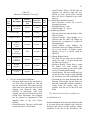
Table IV.
Project/Feature Work Breakdown [14]
Feature
Subtask
Activity
Lead Team
Member
14.8V Battery Regulation
Julio
7.4V Battery Regulation
Christina
Power Supply
System
2 Battery System
15
Feature
Subtask
Activity
Lead Team
Member
Power Failsafe/Battery
Protection
Christina
14.8V Battery Charging
Bogdan
7.4V Battery Charging
Julio
Joystick Packaging
Steven
Joystick Arduino
Communication
Jonathan
Wireless Connection
Loss/Low Battery Alert
Jonathan
Joystick Communication
Jonathan
Servo Communication
Jonathan
Torque Output Research
Steven
Mounting
Julio
Wheel Calibration &
Feedback
Jonathan
Controls/User
Interface
Steering Interface on
Lever Arm
Wireless
Communication
Wireless Xbee
Modules
Servo/Motor and
Sensor Feedback
Servo
Sensor Feedback
16
Feature
Activity
Lead Team
Member
Sensor Research
Bogdan
Sensor Integration
Jonathan
Mount Research and Build
Steven
Weekly Progress Report
Christina
Weekly Project Reports
Christina
Plan Modification
Bogdan
Communication With
Sponsors
Steven
Subtask
Free-Wheel Mode
Mechanical Release
Project
Management
Research and Reports
The team atmosphere throughout the whole design was healthy and motivating. Each member jumped in
when necessary to help in various aspects of the project. In the first semester the team estimated the
number of hours the development of each feature would take. This information along with the actual
number of hours spent is tabulated in Table II [14]. It can be seen that that for the most part, each feature
took more time to complete than was estimated.
Table V.
Project Hours Per Feature [14]
Feature
Power
Supply
System
Controls/User
Interface
Wireless
Communication
Motor and
Sensor
Feedback
Free Wheel
Mode
Total
Predicted Work
Time (hours)
25
30
75
100
60
290
Actual Work
Time
(hours)
60.5
48
57
75
14
254.5
17
Figure 10 is a timeline of the milestones completed in the two semesters [14]. Most of the work was
completed in the second semester, but the first semester set the stage for a successful second semester.
The inclusion of a new team member in the second semester, Julio McClellan, also greatly benefited the
team in the second semester. The research and data gathering of the first semester was very useful. The
planning made early on contributed to the painless completion of the design.
August
2014
Completion of
Wireless
Communication
Feature
Complete
Servo
Feedback
February
2014
November
2014
April
2015
March
2015
Completion of
User Interface
Feature
Complete
Deployable
Prototype
May
2015
Completion of
Power System
and Motor Mount
Fig. 10. Milestones Flowchart [14]
Summing the total hours worked by each member throughout the design, Jonathan Evangelista spent 510
hours, Julio McClellan spent 264 hours (second semester only); Bogdan Svityashchuk spent 448 hours;
Steven Trinh spent 587 hours; Xiaomeng Zhang spent 496 hours. For the entire project a grand total of
2305 hours were worked.
18
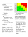
VII. R ISK ASSESSMENT AND M ITIGATION
A. Possible Risks
1) Hardware Failure
Wireless Communication Interference
Stress On the Servos
Not Enough Battery Life
Unexpected damage in critical design
parts (ex: overheating)
Switch responding poorly (debouncing)
Wiring damage due to lever movement
Casters pointing in different directions
2) Software Failure
Delays In System Response
Bugs in software
3) Human Failure
Procrastination
Major team member illness/leaving the
team
Unexpected damage in critical design
parts
Breadboard circuitry (eg. wiring, wrong
pin, etc.)
4) Organizational Failure
Spendings Exceeding Budget
Not Making the Due Dates
Inconsistent with our original design idea
Poor time management
5) External Failure
Unexpected damage in critical design
parts
Throughout the two semesters the team put
together the risk assessment chart shown in
Figure 11. This chart was updated throughout the
life of the project. Fortunately most of the risks
were avoided and the problems that did occur
were solved. Some problems included the
different project schedule of the Mechanical
Engineers and getting parts on time before major
deadlines. These and other problems were
effectively resolved.
Fig. 11. Risk Assessment Chart [14]
B. Possible Risk Mitigation
Making a project modular is a possible way of
mitigating certain risks. This can ensure that the
failure of one piece of hardware does not affect
another piece of hardware. Another approach is
having a backup plan in case an essential part of
the project fails. Listed below are possible risk
mitigation ideas for each area of failure.
1) Hardware Failure
Wireless Communication Interference
Essential to the mitigation of this risk is
finding wireless modules, which operate
at a frequency furthest away from
frequencies that are used by devices like
heart monitors.
Stress On the Servos
Devising a way to have the servo
connected to the caster only when a turn
command occurs.
Not Enough Battery Life
Reducing the total current by taking out
unnecessary parts which use power.
Unexpected damage in critical design
parts (ex: overheating)
Separating the devices so that failure of
one does not affect another too much, but
also keeping in mind economical
packaging.
19
Switch responding poorly (debouncing)
The mitigation and elimination of this
risk can be done using software to ensure
proper responsiveness of a switch
Wiring damage due to lever movement
The wire should be sturdily attached to
the switch circuit and should have a
length that is proper for the movement. It
should also be made easy to access the
wire inside the lever handle for
maintenance purposes.
Casters pointing in different directions
Sensors and servo feedback information
will be used to ensure the proper turning
of the servo make sure the servo returns
to the default straight position.
2) Software Failure
Delays In System Response
Some aspects can be solved in the coding.
Other aspects should be studied and
tested.
Bugs in software
The best idea is to use software, which is
the most bug free, and to use standard
programming practices.
3) Human Failure
Procrastination
Careful planning and motivation from
team leader can eliminate this problem.
Setting up due dates that must be met.
Setting up due dates that are a little early
to be safe and meet the actual due dates.
Major team member illness/leaving the
team
This is highly unlikely since our team
bonded well, but this will not have a too
large impact since we have five people in
the team. Proper distribution of tasks is a
possible mitigation.
Unexpected damage in critical design
parts
Collaborating with the team and not
taking risky steps in the design.
Breadboard circuitry (eg. wiring, wrong
pin, etc.)
Having all team members review the
circuitry can prevent this.
4) Organizational Failure
Spending Exceeding Budget
Reporting all purchases to the sponsor.
Finding approaches with reasonable cost.
Not Making the Due Dates
Settings deadlines earlier than the due
dates
and
have
good
group
communication.
Inconsistent with our original design idea
Following the design criteria since a
certain design is expected. Providing
reasonable evidence that the new features
of added functions are needed.
Poor time management
Team leader will be checking the
progress of each member and ensuring
that deadlines are met. Collaborating with
the team and dividing tasks if they are too
great for one person.
5) External Failure
Unexpected damage in critical design
parts
This failure is external and most of the
time does not depend on the team, but
mitigation can be in the form of proper
separation of the devices and proper
storage of devices.
VIII. PROJECT TASKS
This section will detail the tasks that each
individual member has done, project features, the
general group tasks, total hours worked by each
team member and total hours spent to implement
each feature through out the design process.
A. Project Features
Power System
Control/User Interface
Wireless communication
Servo Sensor feedback
Free Wheel Mode
20
B. Project General Group Tasks for All
Members
Documentation for Problem Statement
Report
Presentation for our Problem Statement
Documentation on Design Idea Contract
Report
Creating Work Breakdown Structure
Market Review and Presentation
Device Test Plan Documentation
Create a Project Timeline
Writing the end-of-term documentation
Writing the end-of-project documentation
Feature Presentation
Mid-term Progress Review and Test
Results Presentation
Deployable Prototype Review and
Presentation
Weekly reports
Team member Evaluations reports
C. Individual Team Member Tasks to Complete
Assigned Feature
Jonathan Evangelista: was assigned to
work on the wireless communication
feature, in addition to the servo and
sensor feedback. He performed tasks on
coding for microcontrollers to complete
wireless communication through the
control user interface via Xbees. He also
helped 3D print the casing for the Lever
arm powering/charging system.
Julio McClellan: was assigned to work on
the power system (charging/ discharging)
design and testing. He was also assigned
to help coordinate with the mechanical
team in terms of implementing the
mounting design for the wheelchair. Julio
also provided lots of valuable input on the
quick-disconnect feature.
Bogdan Svityashchuk: was assigned to
work on the battery voltage control and
device testing. He was the team’s last team leader. In addition to the power
circuit construction and testing, Bogdan
has also been keeping track of the team’s progress, modifying the project timeline
accordingly throughout the semester.
Steven Trinh: was assigned to work on
the mechanical portion for the user
interface and servo sensor feedback
feature. He helped communicate with the
ME team working on the design of our
mounting apparatus. In addition, he
helped the team 3D print the casing for
the servo assembly power system.
Xiaomeng Zhang: was assigned to work
on power system voltage control and
battery charging circuit design. Along
with Julio, they finished the initial design
and simulation of the circuit. She also
was assigned to gather essential electrical
elements and constructed the charging
circuitry prototype.
D. Total Hours Spent by Feature
In total, 60.5 hours were spent to implement the
power system voltage control and charging
feature; 57 hours were spent to implement the
wireless communication feature, 48 hours were
spent to implement the user interface feature, 75
hours were spent to implement servo sensor
feedback feature; and 14 hours were spent to
implement the mechanical quick disconnect
feature.
E. Total Hours Spent by Team member
Summing the total hours worked by each
member throughout the design, Jonathan
Evangelista spent 510 hours , Julio McClellan
spent 264 hours (second semester only); Bogdan
Svityashchuk spent 448 hours; Steven Trinh
spent 587 hours; Xiaomeng Zhang spent 496
hours. A grand total of 2305 hours were worked.
IX. USER MANUAL
A. System Overview
The one arm Wijit wheelchair is a mobility
device designed for the rehabilitation of
people suffering from hemiplegia. Propulsion
21
is achieved by applying force to a lever in a
rowing motion, and steering is achieved with
a joystick control. This device can benefit
people with varying disabilities who have a
need in a one-arm wheelchair. Besides the
joystick control, other steering control can be
customized to the user’s needs.
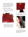
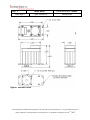
B. Electronics and Caster Installation
1) Installing the Lever Arm Electronics
a. Secure the lids to the box with the
provided screws. The screw positions are
shown in Figure 12 with blue circles
around them [13].
Fig. 13. Mounting Hole for Lever Arm
[13]
c. Ensure that the charging port and switch
are facing towards the rear of the
wheelchair as shown in Figure 14 [13].
Fig. 12. Screws for Lids on Lever Arm
Box [13]
b. Using the provided screw, line up the box
with the hole on the inside of the lever
arm that you will be using. The screw is
inserted into the bottom hole is shown in
Figure 13 with a blue circle around it
[13].
Fig. 14. Port and Switch on the Rear of
the Lever Arm [13]
d. Use zip ties to secure the box to the lever
arm by feeding the zip ties through the
mounting holes on the bottom of the box,
as shown by the arrows in Figure 15, and
tighten until snug [13].
22
b. Make sure that the caster, when engaged,
is in the negative/reverse position as
shown in Figure 17 [13].
Fig. 15. Zip Ties with Mounting Holes [13]
e. Use another zip tie to secure the joystick
to the top of the arm, underneath the shift
control, facing forward, as seen mounted
to the lever arm in Figure 15[13].
f. Be careful as to not over tighten the
screws or the zip ties to minimize the risk
of the plastic box cracking or breaking.
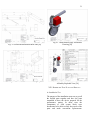
2) Installing the Caster With Gear
. To install the new caster, ensure that the
proper spacers are used, 8 washers on top
with a nut and 8 on the bottom with a nut,
and that the gear is secured to the bolt as
shown in Figure 16 [13].
Fig. 16. Spacers for Caster Gear [13]
Fig. 17. Negative/Reverse Caster Position
[13]
3) Installing the Caster Electronics
a. Attach the motor mount to the side of the
wheelchair that the lever arm electronics
are attached and tighten until snug.
b. Secure the gear to the motor shaft once it
is placed on the mount. Make sure that
one of the setscrews is on the flat part of
the shaft to eliminate slipping as shown in
Figure 18 [13].
Fig. 18. Motor Mounted with Gear [13]
23
c. Secure the motor to the motor mount in
the engaged position with the two wing
nuts and 2 bolts and pins, making sure
that the teeth of the motor gear engage
with the teeth of the caster gear as shown
in Figures 16 and 19 [13].
Fig. 19. Motor Mounted Correctly and
Aligned [13]
d. Attach the caster electronics box to the
support bar on the same side of the
wheelchair, by using the connected
mounts and screws. Tighten until snug.
The mounts are shown with yellow
arrows in Figure 20 [13].
e. The box must be mounted upside down
with the charging port and switch facing
the rear of the wheelchair as shown in
Figure 21 [13].
Fig. 21. Correct Caster Electronics
Mounting [13]
f. Be careful to not over tighten any screws
or mounts as they may damage the
wheelchair itself, the mounts, or box.
g. Once everything is secured, connect the
5-pin connector from the box to the motor
as shown in Figure 22 [13].
Fig. 22. Motor and Electronics Connection [13]
Fig. 20. Caster Electronics Box Mounting [13]
24
h. Lastly, install the fuse into the hole in the
side of the box as shown in Figure 23
with a yellow circle [13].
Fig. 23. Fuse Location [13]
C. Getting Started
1) Safety Guidelines/Precautions
MAKE
SURE
ALL
THE
ATTACHMENTS ARE SECURELY
INSTALLED
AVOID IMPACT TO THE
ELECTRONICS HOUSING
TWO
DO NOT CHARGE THE BATTERIES
WITHOUT READING THE CHARGING
INSTRUCTIONS
CHARGE THE BATTERY ON A NONFLAMMABLE SURFACE IN A COOL
ENVIRONMENT
WITH
ENOUGH
VENTILATION.
DO NOT LEAVE THE BATTERY
CHARGING WITHOUT SUPERVISION
CHARGE THE BATTERY ONLY IF
THE LOW BATTERY BUZZER ALARM
GOES OFF
IMMEDIATELY DISCONNECT THE
DC CHARGER AND FLIP THE 3-WAY
SWITCH TO THE OFF POSITION IF
SMOKE IS OBSERVED OR THE
BATTERY BEGINS TO SWELL
2) Powering On
Step 1. The Motor Control Unit should be
powered on first. This unit is powered by
flipping the switch to the O (On) position.
The switch is located on the back of the
wheelchair. The other position, C (Charge) is
used when charging the battery. Refer to the
charging section before charging the
batteries.
Step 2. Next, the Lever Arm Unit can be
powered by flipping the switch to the O (On)
position. This switch is located on the rear of
the lever arm. Next, move the joystick left
and right to see if the motor controlled caster
turns. If the casters don’t turn, refer to the troubleshooting section.
3) Using the Wijit Lever Arms
Step 1. The lever arms should be in the
neutral position with the shifter knob in the
center.
Step 2. Shift the knob either inwards to move
forward or outwards to move backward.
Once shifted, move your hands down the
lever arm away from the knob and move the
lever arms in a rowing motion either forward
or backward to achieve the desired motion.
Step 3. To make turns you can either hold
one side and just move one arm or alternate
one arm forward and one arm backward.
Step 4. To stop, pull in on the arms toward
yourself and the wheelchair will brake.
4) Operation
Step 1. To move the wheelchair you will still
use the same shifting and rowing motion as
described in the “Using the Wijit Lever Arms” section, but instead you will be only using one arm.
Step 2. To turn use the joystick and move it
either the left or right to turn in that direction.
Make sure to be moving already before
turning the caster with the joystick.
Step 3. To turn in reverse use the joystick
again as described above, but make sure to
have the wheelchair already moving in
reverse with the lever arm before turning the
caster with the joystick.
25
Step 4. To brake simply release your
fingers/hand from the joystick pull the one
arm you are using to control with inward,
toward yourself.
5) Powering Off
Step 1. Move the switch on the Lever Arm
Unit to the center position.
Step 2. Move the switch on the Motor
Control Unit to the center position.
Step 3. Remove the fuse from the Motor
Control Unit.
6) Entering Free-Wheel Mode
Step 1. Remove both wingnuts that is
attached to the servo.
Step 2. Slide the servo back to the second set
of screw holes on the mount
Step 3. Tighten the wingnut back onto the
mount.
Step 4. Now you can freely move the
wheelchair.
7) Charging
During wheelchair operation, if the buzzer
alarm goes off, then it is a good indication of
low battery.
Step 1. To charge up the battery, simply take
a DC charger, with output set to 18.5V, and
plug it into the DC charging port on the
battery case.
Step 2. Flip the 3-way switch to “C” setting to charge for both the Motor Control
Step 3. Charging should take about 30 to 45
minutes.
Step 4. When charging is done flip the 3-way
switches back to the center off position.
Step 5. Unplug the DC charger and you are
ready to go!
XI. HARDWARE
A. Overview
Our design is comprised of two separate units.
One unit interfaces with the user and takes in
directional commands. The second unit receives
the commands and then controls position of the
front caster wheel. The electronic hardware used
in each unit is listed as follows:
User Interface
7.4v LiPo Battery
Battery Protection Circuit
8.4v Regulated Charging Circuit
Xbee Transceiver
Arduino Micro
Manual 3-Way Toggle Switch
Servo Control
14.8v LiPo Battery
Battery Protection Circuit
16.4v Regulated Charging Circuit
12v Linear Regulator
7.5v Linear Regulator
Xbee Transceiver
Arduino Micro
Manual 3-Way Toggle Switch
During charging operation a single 18.5v DC
Power Supply is used to supply the required
charging power to each unit.
B. Flow Charts
X. DESIGN DOCUMENTATION
This section was meant to include documentation
not included anywhere else in the report. It is not
used due to the fact that all significant
information is documented in other sections.
Fig. 24. Power Flow During Charge [28]
26
Fig 27. Simulation of User Interface Power
Circuit [28]
Fig. 25. Power Flow During User Operation [28]
C. Schematic Diagrams and Simulation
Figure 27 shows the simulation of our User
Interface Circuit when the battery has reached a
low voltage of 6.5v [28]. The schematic in
Figure 27 shows a LM7805 linear regulator. The
LM7805 is the on-board regulator used by the
Arduino Micro to create it’s required 5v supply.
XII. SOFTWARE
A. Overview
Fig. 26. Simulation of Servo Power Circuit [28]
Figure 26 shows the simulation of our Servo
Control Circuit when the battery has reached a
low voltage of 13.0v [28]. During prototyping we
employed the use of a LM7812 circuit. The
schematic in Figure 26 shows a LT1084 linear
regulator instead. The LT1084 is a better
component for this application than the LM7812,
as it has a low-dropout voltage and available
current of 5A. The load resistor R1 in the circuit
represents the Servo load. The load resistor R2 in
the circuit represents the Arduino load. These
load resistance values are not the actual load
resistances of their respective assemblies and are
only used to simulate maximum manufacturer
specified current draw.
Software is a major component of our
system. The software used is programmed on
the Arduino Micros that allow for serial and
wireless communication with XBee modules.
There are two major pieces of code that are
called WriteOut and ReadIn. The process in
which the hardware and software interact is
conceptualized in the form of a flow chart as
seen in Figure 28 [29]. The WriteOut code is
uploaded to the Arduino Micro that is
connected to the lever arm electronics
assembly, while the ReadIn code is uploaded
to the Arduino Micro that is connected to the
caster electronics assembly. The WriteOut
code is responsible for interpreting the
position of the joystick, which is located in
the lever arm electronics assembly, and from
that position it sends a data character over
serial to the XBee module. Then the data
character is sent wirelessly to the caster
electronics assembly. The other XBee
module located in the caster electronics
assembly receives this data character and it is
transmitted over serial to the Arduino Micro.
The ReadIn code then interprets this data
27
character and sends a pulse width modulation
signal, with the Arduino servo library, to the
servomotor to turn it in the correct direction.
A feedback signal is used from the
servomotor to tell if it has turned correctly,
and if not tries to turn again to the correct
position. Additionally, the ReadIn code has a
check to make sure that the wireless
communication with the XBee module is
working, and if it is not working alerts the
user with a buzzer sound.
B. Flow Chart
PRINT “D” to Serial1
SET delay to 10
ELSE IF LR <= 1032 AND
LR >= 516
PRINT “L” to Serial1
SET delay to 10
ELSE IF LR <= 500 AND LR
>= 0
PRINT “R” to Serial1
SET delay to 10
END IF
END IF
}
2) ReadIn
#include <Servo.h>
SET servo to servo1
SET msg to ' ' //Var for message sent via
xbee serial
SET volt1 to 0 //Variable for feedback
voltage from pot
SET speakerOut to 6 //for digital pin to
buzzer
Fig. 28. Software Code Flow Chart [29]
C. Pseudocode
1) WriteOut
SET LR to 0 //variable for the position of the
joystick
void setup()
{
SET Serial begin to 9600
SET Serial1 begin to 9600 //For arduino
micro
}
void loop()
{
READ pin A5
SET LR to read value
//Adjust LR range values for return to
center sensitivity
IF Serial1 is TRUE
IF LR < 516 AND LR > 500
void setup() {
SET servo1 attach to 10 //servo
digital pin
SET pinMode of spearkout to
OUTPUT
SET Serial begin to 9600
SET Serial1 begin to 9600 //For
arduino micro
}
void loop() {
IF Serial1 is TRUE
READ serial1 character
SET msg to read value
READ pin A5
SET volt1 to read value
CONVERT volt1 value to voltage1 value
between 0 and 5 volts
IF voltage1 <= 4.4 //Low battery alert
SET tone to 800 for speakerOut
SET delay to 1000
SET noTone for speakerOut
SET delay to 3000
28
END IF
IF msg == ‘L’
SET servo1 write to 110
IF !(voltage <= 1.05 AND
voltage1 >= 1.03)
SET servo1 write to 110
END IF
ELSE IF msg == ‘D’
SET servo1 write to 90
IF !(voltage <= 1.77 AND
voltage1 >= 1.75)
SET servo1 write to 90
END IF
ELSE IF msg == ‘R’
SET servo1 write to 75
IF !(voltage <= 2.96 AND
voltage1 >= 2.94)
SET servo1 write to 75
END IF
ELSE
SET tone to 700 for speakerOut
for 150
SET delay to 200
SET tone to 700 for speakerOut
for 150
SET delay to 200
SET tone to 700 for speakerOut
for 150
SET delay to 200
SET tone to 700 for speakerOut
for 150
SET delay to 200
SET noTone for speakerOut
SET delay to 5000
END IF
motor’s lack of holding torque, we were forced to go with a different iteration of this mount.
The team’s sponsor had given us a different wheelchair so we had to adjust the design to fit
the more clinical wheelchair. The second
iteration includes a high torque industrial servo
motor and a gear system as shown in Figures 36
through 39 [30]. The mechanical mount was
made smaller and the quick release was made
into a sliding rail that had a thumbscrew to lock
into place the gears. A new front caster was also
made so it would give enough room to add the
gears and adjust the height as needed. The gears
were in a 2:3 ratio to assist the servo speed. The
gear on the servo translates the motion onto the
gear that is on the caster that turns it or keeps it
straight. This design broke in the end and we had
to redesign something that would have more
strength.
The third iteration of the mechanical mount was
still a gearing system but a redesign of the mount
itself as shown in Figures 40 through 42 [30].
The mechanical engineers made it more rigid and
included a different way to quickly release it to
turn it into a standard wheelchair. To accomplish
the standard wheelchair mode, the user will have
to unscrew two wingnuts and slide the mount
back and secure it back into place. The
mechanical engineering team that worked with
our team throughout both semesters created all of
the images and designs.
XIII. M ECHANICAL WORK
The mechanical mount has gone through three
iteration and design changes based on the criteria
and feedback our sponsor has given to us. The
first iteration included a lever arm system with
quick release pins to turn it into a standard
wheelchair as shown in Figures 29 through 35
[30]. The lever arm translated the motion from
the stepper motor to the front caster, which
turned the wheelchair itself. Due to the stepper
Fig. 29. First Iteration Assembly [30]
29
Fig. 30. First Iteration Exploded View [30]
Fig. 33. First Iteration Bracket End Left Rod Fork
[30]
Fig. 31. First Iteration Bracket Left Caster Wheel
[30]
Fig. 34. First Iteration Lever Arm [30]
Fig. 32. First Iteration Bracket Right Caster Wheel [30]
30
Fig. 35. First Iteration Right End Rod Fork [30]
Fig. 37. Second Iteration Motor Mount [30]
Fig. 36. Second Iteration Pre-bent caster [30]
Fig. 38. Second Iteration Motor Front End
[30]
31
Fig. 39. Second Iteration Motor Rear End [30]
Fig. 40. Third Iteration Motor Mount [30]
Fig. 41. Third Iteration Fully Assembled
Drawing [30]
Fig. 42. Third Iteration Caster
Assembly Exploded View [30]
XIV. HARDWARE TEST PLAN AND RESULTS
A. Installation Test
The purpose of the installation tests was to get all
the needed parts together and have the parts
assembled to have the device prepared for the
performance testing. In these tests the
components of each system block were
documented to be able to easily keep track of the
parts and make convenient replacements.
32
Additionally, some of these parts needed cases to
be made to hold them securely to the wheelchair.
To do this, 3D printed cases were designed and
made. The mounting and mechanical hardware is
listed below. The electronics hardware is listed in
the software installation testing section.
1.4 Servo Assembly and Hardware
o Components: Servo, shaft extender,
gears, servo mount
o Comments: All components are present
and mounted
1.5 Servo Disconnect Hardware
o Components: Gears, servo mount, pins
o Comments: The quick release hardware is
available with the motor made to
disengage from the gears.
B. Operation Tests
The purpose of the operation tests was to test
each of the individual components of our project
to ensure that they work correctly. For each
separate component there were different types of
tests that needed to be performed. Operational
testing is important to our project because at this
point we can tell if we need to change our design,
the hardware, or the software in order for the
system to work correctly.
2.5 Servo Functionality
o Description: The servo functionality was
tested by using our system with
everything connected including the power
systems and both Arduino Micros. Then
the servo was observed as the joystick
was moved to ensure that the servo was
turning to the correct position
corresponding to the position of the
joystick.
2.6 Servo Quick Disconnect
o Disconnect: The free wheel mode was
tested by disengaging the gears with by
taking out the pins and moving the motor
back.
Table VI.
Hardware Operation Tests [14]
Test
I.D.
Test
Description
Person(s)
Date Test Pass
Performing Performed /Fail
Test
2.5
Servo
Functionality
Jonathan
3/7/2015
Pass
2.6
Servo Quick
Disconnect
Steven
3/7/2015
Pass
C. Performance Test
The purpose of the performance test was to
determine as well as ensure that our design meets
minimum requirements with respect to
performance measurements. Meeting these
requirements serves as indication that the design
functions and operates as expected. Due to a
required mechanical redesign some of the tests
were initially delayed during the time of our
initial testing. With the completion of the third
iteration of the mechanical mounting, all other
tests were completed and showed great results.
3.6 Servo Range of Motion
o This test was intended to test the steering
capabilities of the wheelchair in both
directions.
o Left of Center
Expected Results: 35 degrees
Actual Results: 36 degrees
o Right of Center
Expected Results: 125 degrees
Actual Results: 123 degrees
This test gave very good results with the
wheelchair doing great on both left and
right turns.
3.7 Servo Response Time
How much time it takes from a user moving
the joystick to the servo motor
Expected Results: 1 second
Actual Results: 0.8 – 1 second(s)
33
Actual Results: With a 250 lbs load, no
slippage was observed when the user
picked up some speed before steering
since less force is applied to the caster
that way.
3.9 Mechanical Quick Disconnect
o How much time it takes for a user to
disengage the motor.
o Expected Results: 1 min.
o Actual Results: 30 – 60 sec.
3.10 Braking Distance
o This test passed by using the brake of the
Wijit lever arm.
o Expected Results: Upon braking, it is
expected that the chair will change its
direction by a maximum of 2 inches of
slipping distance.
o Actual Results: Upon braking, the
wheelchair does not change direction at
all at slow speeds. At higher speeds
slippage of up to 2 inches could be
observed.
3.11 Ramp Braking Limits
o The ramp test was done on two different
ramps, one with a 3 degree incline and
the other one 6 degrees.
o Expected Results: Going down a ramp
the brakes will work without any
swerving, but going up, the chair might
swerve 3-6 inches when braking.
o Actual Results: The chair could easily go
up and down the 3 degree ramp. Braking
up and down was also comfortable and
prevented the user from crashing into the
sidewall. Going up the 6 degree ramp was
basically impossible without assistance.
Going down the steeper ramp was
possible with the use of the lever arm
brake.
o
Table VII.
Hardware Performance Tests [14]
Person(s)
Performing
Test
Date Test
Performed
Pass/
Fail
Steven
3/14/2015
Pass
Left of Center
Steven
4/14/2015
Pass
Right of Center
Steven
4/14/2015
Pass
Test
I.D.
Test
Description
Servo Range
of Motion
3.6
3.7
Servo
Response
Time
Jonathan
3/14/2015
Pass
3.8
Servo Load
Limit
Performance
Julio
4/14/2015
Pass
3.9
Mechanical
Quick
Disconnect
Steven
3/14/2015
Pass
3.10
Braking
Distance
Steven
4/14/2015
Pass
3.11
Ramp Braking
Limits
Bogdan
4/14/2015
Pass
3.8 Servo Load Limit Performance
o Having a high load on the wheelchair to
see if the servo can handle the load and
turn the wheelchair. The lightest people
in the team were part of the test. No gear
slippage was observed when going
forwards or backwards. Some gear
slippage was observed when the heaviest
person drove backwards. This slippage
can be reduced or eliminated by first
applying force to the lever before
steering.
o Expected Results: The servo will be able
to turn with up to a 250 lbs load.
XV. SOFTWARE TEST P LAN AND RESULTS
A. Installation Tests
For the installation tests, the proper hardware had
to be setup before the program code could be
uploaded and tested on the Arduino Micros
connected to the rest of the electronics. The
34
installation tests that were necessary were the
lever arm electronics assembly and the caster
electronics assembly.
1) Lever Arm Electronics Assembly
a. Components: Arduino Uno, Xbee
Transmitter, Joystick, 7.4V LiPo battery
b. Result: All of the components are
installed and present. The electronics are
encased in a 3D modeled and printed box.
2) Caster Electronics Assembly
a. Components: Arduino Uno, Xbee
Receiver, 14.8V LiPo battery, 12V
Regulation circuit, 7V Regulation circuit
b. Result: All of the components are
installed and present. The electronics are
encased in a 3D modeled and printed box.
B. Operation Tests
For the operation tests, the lever arm
microcontroller,
the
servo
assembly
microcontroller, and the XBee communication
were tested to ensure that everything was able to
work correctly before integrating into the whole
system. These tests were performed by uploading
the code to the respective microcontrollers.
1) Lever Arm Microcontroller
a. Description: The lever arm
microcontroller was tested to ensure that
it would be able to read the values of the
position of the joystick correctly. This
was tested by observing the serial output
on the Arduino IDE via USB connected
to a computer.
b. Result: Passed
2) Servo Assembly Microcontroller
a. Description: The servo assembly
microcontroller was tested to ensure that
it would be able to read the correct values
read from the feedback of the servo to
ensure the servo turned correctly. This
was tested by observing the serial output
on the Arduino IDE via USB connected
to a computer.
b. Result: Passed
3) ZigBee Communication
The Zigbee communication was tested by
connecting both Arduino Micros to my
computer via USB with the Xbee modules
attached. Then the 2 serial monitors were
watched from the Arduino IDE to ensure that
the correct signals being sent were being
received on the other end.
a. Result: Passed
C. Performance Tests
For
the
performance
tests,
the
communication data and error rate were
tested to ensure that the software written was
able to communicate effectively with the
hardware over a wireless connection. These
tests were performed by uploading the code
to the respective microcontrollers and
including extra code, with the micros arduino
function, to test the communication time.
1) Communication Data Rate
a. Expected Result: 9600 bits/s or 1200
bytes/s
b. Actual Result: 9615 bits/s or 1201 bytes/s
2) Communication Error Rate
a. Expected Results: 0.2%
b. Actual Results: 0.15%
XVI. CONCLUSION
With the results obtained through the assembly
and testing phase of our design, we have
achieved a successful deployable prototype of a
single-arm Wijit wheelchair system. Through the
addition of approximately 7 lbs of hardware, we
have created a modular device that enables
persons limited to the use of one side of the
body, to achieve mobility through their own
physical exertion. Functionality, performance,
and safety are all essential components of our
design, while providing a means for
neuromuscular integration in the lives of
hemiplegic patients being the desired final
outcome. Although our prototype has some
limitations with respect to grade and landscape, it
is still a strong proof of concept for a electromechanical one-arm wheelchair system. By
using available modern electronics such as
microcontrollers, high torque servos, Xbee
35
wireless technology, and modern battery design
(Lithium Polymer), we have created an effective
system for hemiplegic patients to experience
both mobility and the benefits of exercise with
only one arm. With the help of industry sponsors,
CSUS faculties, a UC Davis Biomedical
Engineering team, and a CSUS Mechanical
Engineering team, Team Tijiw has integrated all
the key features of a Design Idea into a durable
and condensed mechanism for the improved
quality of life of hemiplegic patients. Our team
has fully implemented our year-long project into
a wholly integrated system that we feel will meet
the consumer needs, as well as satisfy those of
our industry sponsor. In doing so, we hope that
this system will be an effective and easy to use
method for hemiplegic patients to enjoy the
benefits of the Wijit wheelchair system and
physical neuromuscular integration.
36
REFERENCES
[1]
A. Howell, T. Kobayashi, H. Hayes, K.
Foreman,
S.
Morris
Bamberg.
(2013,Dec.). Kinetic Gait Analysis Using
a Low-Cost Insole. IEEE Transactions on
Biomedical
Engineering.
[Online].
60(12), pp. 3284–3290. Available:
http://ieeexplore.ieee.org.proxy.lib.csus.e
du/stamp/stamp.jsp?tp=&arnumber=6473
842
[2]
D. Shah, D, Balusamy, M. Verma, G. Jui.
(2013,Dec.). Comparative Study of the
Effect of Taping On Scapular Stability
and Upper Limb Function in Recovering
Hemiplegics With Scapular Weakness.
Chronicles of Young Scientists. [Online].
4(2), pp. 121–129. Available:
http://eds.a.ebscohost.com.proxy.lib.csus.
edu/ehost/pdfviewer/pdfviewer?sid=a985
4cf0-33b7-4902-b894603568bd52e1%40sessionmgr4003&vid
=1&hid=4213
[3]
Hemiplegia and Hemiparesis. Stroke
Rehab.
[Online].
Available:
http://www.strokerehab.com/hemiplegia.html
[4]
Hemiplegia. Medical Show. [Online].
Available:
http://medicalshow.blogspot.com/2012/0
5/hemiplegia.html
[5]
[6]
Physical Activity for People With
Mobility Issues or Disabilities. Active
Living.
[Online].
Available:
http://www.healthyalberta.com/626.htm
N. Vujicic. Bio. Life Without Limbs.
[Online].
Available:
http://www.lifewithoutlimbs.org/aboutnick/bio/
[7]
M. Boninger, A. Koontz, S. Sisto, T.
Dyson-Hudson, M. Chang, R. Price, R.
Cooper.
(2005,Nov.).
Pushrim
Biomechanics and Injury Prevention In
Spinal Cord Injury: Recommendations
Based On CULP-SCI Investigations.
Journal of Rehabilitation Research &
Development. [Online]. 42(3), pp. 9–20.
Available:
http://slayerwheels.com/contents/enus/Wheelchair%20Pushrim%20Biomecha
nics%20and%20Injury%20Prevention.pd
f
[8]
Wijit. Innovations Health. [Online].
Available:
http://www.innovationshealth.com/produ
cts/wijit/meet-wijit/
[9]
F. Medola, P. Dao, J. Caspall, S.
Springle.
(2014,Mar.).
Partitioning
Kinetic Energy During Freewheeling
Wheelchair
Maneuvers.
IEEE
TRANSACTIONS
ON
NEURAL
SYSTEMS AND REHABILITATION
ENGINEERING. [Online]. 22(2), pp.
326–333. Available:
http://ieeexplore.ieee.org.proxy.lib.csus.e
du/stamp/stamp.jsp?tp=&arnumber=6656
838
[10]
Glide One Arm Drive Wheelchair.
Alphacare.
[Online].
Available:
http://alphacare.com.au/rehabilitationequipment/wheelchairs/hemiplegicwheelchairs/glide-one-arm-drivewheelchair/
[11]
(2003) Invacare IVC CLD. Invacare IVC
Manual Wheelchair Series. [Online].
Available:
http://www.invacare.com/product_files/0
0-261%20rev%2010_03.pdf
37
[12]
D. DiGiovanni, V. Marrion, H. Nina.
(2009,Apr.).
One-Arm
Manual
Wheelchair. Worchester Polytechnic
Institute. [Online]. Available:
https://www.wpi.edu/Pubs/Eproject/Available/E-project-043009105716/unrestricted/Wheelchair_MQP_0
809.pdf
[13]
J.Evangelista. User Manual Pictures.
2015.
[14]
Team Tijiw. Pictures and Drawings.
2015.
[15]
K. Robertson. (2012,Mar.). Wheelchair
Company Ramps Up Sales Efforts.
Sacramento Business Journal. [Online].
Available:
http://www.bizjournals.com/sacramento/p
rint-edition/2012/03/02/wheelchaircompany-ups-sales-effort.html?page=all
[16]
[17]
[18]
[19]
M. Brault. Americans With Disabilities:
2010. United States Census Bureau.
[Online]. Available:
http://www.census.gov/prod/2012pubs/p7
0-131.pdf
Disability in America Infographic.
Disabled World. [Online]. Available:
http://www.disabledworld.com/disability/statistics/americandisability.php
D. Walker. (2013,Mar). Spotlight on
Cerebral Palsy 1: Cerebral Palsy and
Aging. Griswold Home Care. [Online].
Available:
http://www.griswoldhomecare.com/blog/
spotlight-on-cerebral-palsy-1-cerebralpalsy-and-aging/
Cerebral Palsy: Hope Through Research.
National Institute of Neurological
Disorders
and
Stroke.
[Online].
Available:
http://www.ninds.nih.gov/disorders/cereb
ral_palsy/detail_cerebral_palsy.htm#2690
03104
[20]
Health Care. U.S. Department of
Veterans Affairs. [Online]. Availabe:
http://www.va.gov/
[21]
Spinal
Cord
Injury
Information.
Paralyzed Veteran’s of America.
[Online].
Available:
http://www.pva.org/site/c.ajIRK9NJLcJ2
E/b.6344373/k.4182/Spinal_Cord_Injury
_Information.htm
[22]
SCI Centers. Department of Veterans
Affairs.
[Online].
Available:
http://www.sci.va.gov/SCI_Centers.asp
[23]
Role of Physical Therapist Assistant
(PTA). American Physical Therapy
Association.
[Online].
Available:
http://www.apta.org/PTACareers/Roleofa
PTA/
[24]
Role of a Physical Therapist. American
Physical Therapy Association. [Online].
Available:
http://www.apta.org/PTCareers/RoleofaP
T/
[25]
Occupational
Therapy:
Improving
Function While Controlling Costs. The
American
Occupational
Therapy
Association.
[Online].
Available:
http://www.aota.org/About-OccupationalTherapy/Professionals.aspx#sthash.lMIM
iQ34.dpuf
[26]
Post-Stroke Rehabilitation Fact Sheet.
National Institute of Neurological
Disorders
and
Stroke.
[Online].
Available:
http://www.ninds.nih.gov/disorders/strok
e/poststrokerehab.htm
38
[27]
Stroke Rehabilitation. Yellow Pages.
[Online]. Available:
http://www.yellowpages.com/sacramento
-ca/stroke-rehabilitation?
[28]
J. McClellan. Hardware/Electronic
Flowcharts. 2015.
[29]
J.Evangelista. Software Flowchart. 2015
[30]
M.Peri, S. Randhawa, S.Hiep. Professor
Rustin Vogt. Sacramento State University
Mechanical Engineering Team.
Mechanical Drawings. 2015.
GLOSSARY
Geriatrics: The branch of medicine or
social science dealing with the health and
care of old people.
Hemiplegia: Total or partial paralysis of
one side of the body that results from
disease of or injury to the motor centers
of the brain.
Neuromuscular: Of or relating to nerves
and muscles.
39
APPENDICES
APPENDIX A. TEAM CONTACTS AND THANK YOU LETTERS
Contacts:
The contacts we have made are as followed: Brian Watwood, John Rhea, Warren Smith, Fethi
Belkhouche, Russ Tatro, Dennis Dahlquist, Rustin Vogt, Akihiko Kumagai, Patrick Homen, Mike
Newton. Also we collaborated with a UCD Biomedical student team: Chris Zikry, Phuong Dang, Dat Ho,
Marcel Bernucci, and their Professor, Anthony Passerini. We are also grateful we were able to work with
a CSUS ME team including Michael Peri, Sophaly Hiep, and Simi Randhawa
The person who has helped the most is Dr. Warren Smith. With his knowledge and his connections, he
has provided us with an industry sponsor that was willing to give us a project and was willing to give us
alternative projects aside from the Wijit project. Without Dr. Smith’s assistance, the team would have not gotten this project.
Brian Watwood and John Rhea are other people who we have had the most contact with. They had
provided us funding for this project and also insight on what their vision is for this project.
Communication with them is key in order to have a successful project and a satisfied sponsor.
The Electrical Engineering professors were very helpful and encouraging. Professor Dennis Dahlquist
from our first semester lab and Professor Russ Tatro from the second semester consistently gave us
feedback on what is needed to make our project a success. Their feedback and guidance helped lead us
towards the right direction in our project. Dr. Fethi Belkhouche and Professor Russ Tatro were available
for the senior design students if they had any questions that needed clarification.
We also made contact with the Mechanical Engineering department. Dr. Patrick Homen, Dr. Rustin Vogt,
and Dr. Akihiko Kumagai were a huge help with conceptualizing the mechanical aspects of the project.
We would like to have a special thanks to Mike Newton for assisting us on our design for the casters and
for fulfilling our work order.
40
Thank you letters:
Dear Brian Watwood,
Thank you again for being our industry sponsor for this project. Discussing your project to the senior
project group was very informative and our team enjoyed hearing about your vision to help rehabilitate
hemiplegic patients. We are convinced that our team will complete this project in a way that you have
envisioned it or even better! Thank you again for allowing us the opportunity to work with you and
answer some of our questions. We look forward to seeing you soon.
Sincerely,
Team Tijiw:
Jonathan Evangelista
Julio McClellan
Bogdan Svityashchuk
Steven Trinh
Christina Xiaomeng Zhang
Dear John Rhea,
Thank you again for assisting us and Brian Watwood for this project. Discussing the project to the senior
project group was informative and our team enjoyed hearing about your vision to help rehabilitate
hemiplegic patients. Your knowledge and insight on the wheelchair really helped us progress along with
the project. We are convinced that our team will complete this project in a way that you have envisioned
it or even better! Thank you again for allowing us the opportunity to work with you and answer some of
our questions. We look forward to seeing you soon.
Sincerely,
Team Tijiw:
Jonathan Evangelista
Julio McClellan
Bogdan Svityashchuk
Steven Trinh
Christina Xiaomeng Zhang
Dear Dennis Dahlquist,
Thank you so much for offering us your priceless ideas for the project and always leading us in the
correct direction. Your humor and approach to the project made the design a lot less stressful. We really
appreciate the time that you contributed to our team. Also big thank you for not giving us all the answers,
but making us think and feel like we’re doing real engineering.
Sincerely,
41
Team Tijiw:
Jonathan Evangelista
Julio McClellan
Bogdan Svityashchuk
Steven Trinh
Christina Xiaomeng Zhang
Dear Warren Smith,
Thank you again for getting in contact with our industry sponsor for this project. Presenting us with
initial ideas that lead to our project really gave us an idea of what direction we wanted to head towards.
We are convinced that our team will complete this project in a way that you have envisioned it or even
better! Thank you again for allowing us the opportunity to work with you and answer some of our
questions. We look forward to seeing you soon.
Sincerely,
Team Tijiw:
Jonathan Evangelista
Julio McClellan
Bogdan Svityashchuk
Steven Trinh
Christina Xiaomeng Zhang
Dear Fethi Belkhouche,
Even though you were not our senior design instructor, we would like to thank you for being available for
us to ask questions about the Computer Engineering and Electrical Engineering aspects of our project.
We are convinced that our team will complete this project in a way that you have envisioned it or even
better! Thank you again for allowing us the opportunity to work with you and answer some of our
questions. We look forward to seeing you soon.
Sincerely,
Team Tijiw:
Jonathan Evangelista
Julio McClellan
Bogdan Svityashchuk
Steven Trinh
Christina Xiaomeng Zhang
42
Dear Russ Tatro,
The team Tijiw is very grateful that you were our second semester lab instructor. Your guidance and
motivation helped us greatly. Thank you so much for being so involved with our project and always
pointing us in the right direction. We greatly appreciate the timely feedback we received from you.
Senior design would not be as fun and challenging without you and we thank you for the lessons you
have given us.
Sincerely,
Team Tijiw:
Jonathan Evangelista
Julio McClellan
Bogdan Svityashchuk
Steven Trinh
Christina Xiaomeng Zhang
Dear Akihiko Kumagai,
Even though you were not our senior design instructor, we would like to thank you for being available for
us to ask questions about the Mechanical Engineering aspects of our project. We are convinced that our
team will complete this project in a way that you have envisioned it or even better! Thank you again for
allowing us the opportunity to work with you and answer some of our questions. We look forward to
seeing you soon.
Sincerely,
Team Tijiw:
Jonathan Evangelista
Julio McClellan
Bogdan Svityashchuk
Steven Trinh
Christina Xiaomeng Zhang
Dear Rustin Vogt,
Even though you were not our senior design instructor, we would like to thank you for being available for
us to ask question while we worked on our project. We would also like to thank you for assisting both the
Mechanical and the Electrical Engineering senior design group. We are convinced that our team will
complete this project in a way that you have envisioned it or even better! Thank you again for allowing
us the opportunity to work with you and answer some of our questions. We look forward to seeing you
soon.
Sincerely,
43
Team Tijiw:
Jonathan Evangelista
Julio McClellan
Bogdan Svityashchuk
Steven Trinh
Christina Xiaomeng Zhang
Dear Patrick Homen,
Even though you were not our senior design instructor, we would like to thank you for being available for
us to ask question while we worked on our project. We are convinced that our team will complete this
project in a way that you have envisioned it or even better! Thank you again for allowing us the
opportunity to work with you and answer some of our questions. We look forward to seeing you soon.
Sincerely,
Team Tijiw:
Jonathan Evangelista
Julio McClellan
Bogdan Svityashchuk
Steven Trinh
Christina Xiaomeng Zhang
Dear Mike Newton,
We would like to thank you for assisting us on making our motor mount. Without your assistance, we
would have not gotten a mount that would work with the current design we have. We are convinced that
our team will complete this project in a way that you have envisioned it or even better! Thank you again
for allowing us the opportunity to work with you and answer some of our questions. We look forward to
seeing you soon.
Sincerely,
Team Tijiw:
Jonathan Evangelista
Julio McClellan
Bogdan Svityashchuk
Steven Trinh
Christina Xiaomeng Zhang
APPENDIX B. TEAM M EMBER RESUMES
Jonathan Frank Evangelista
---------------------------------------------------------------------------------------------------------------------------------------------------------------------------------------------------------------------------------------------------------------------
Objective:
To learn about information security and software engineering, while gaining more experience and knowledge in the engineering and
Information Technology field, and applying my engineering and computer skills to benefit government organizations.
Education:
•
California State University, Sacramento
o Major: Computer Engineering; BS in progress; Expected Graduation: Spring (May) 2015; GPA: 3.55
o CyberCorps: Scholarship for Service student
Abilities/Skills:
•
•
•
•
Programming Languages: Java, Verilog, x86 Assembly, PHP, XML, Python, and HTML. Currently learning: C
Operating Systems: Windows XP, Windows 7, Linux, and Mac OSX
Software: MS Office, jGrasp, Xilinx ISE, intelliJ, Eclipse, Altiris, and Symantec Ghost
Organizational and Communication Skills:
o Communicated information effectively in a detailed step-by-step process that is understandable to any receiver, through
my written and oral skills that I learned through labs, group work, and multiple projects from my work experience.
o Acquired analytical and problem-solving skills through hardware and software projects, troubleshooting problems at work,
and different computer lab activities.
o I am exceptionally organized, self-motivated, and dependable. For example, I am able to manage work projects and school
projects and labs at the same time, while always completing projects before the specified deadlines.
Job Experience:
•
•
•
Department of the Army, U.S. Army Corps of Engineers, IWR, HEC
Dec 2013 - Present
o Student Trainee (Computer Science)
o Assisted the staff in Water Management Systems Division with programming assignments.
o Supported components of CWMS (Corps Water Management System).
o Worked on scripting within the UNIX environment.
o Used programming languages such as Python and Java.
OWP (Office of Water Programs) at Sacramento State University
Mar 2013-Nov 2013
o Student Assistant- IT Software Developer/Hardware Support
o Assisted the IT technical support staff with web development and hardware support related projects.
o Worked with other programmers to test and develop code vital to the operation of OWP.
o Worked with hardware support to maintain the computers and peripherals at OWP.
o Used programming languages such as PHP and JavaScript.
SMUD (Sacramento Municipal Utility District)
Mar 2012-Mar 2013
o Student Staff Assistant for IT Department- Hardware Support Group
o Supported the IT hardware staff with multiple computer related issues, such as Ergonomics, Break/Fix computers, servers,
printers and scanners, re-imaging computers, and troubleshooting problems such as through the BIOS, throughout the
SMUD district.
o Used the Altiris ticketing system and database to keep records of the work that was performed, and make sure all
equipment was accounted for.
Honors and Awards Received:
•
•
•
•
•
•
Achieved Dean’s Honor Roll at Sacramento State
Awarded John C. Gist Book Scholarship- Fall 2011
Awarded OSE (Organization of SMUD Employees) Scholarship- Fall 2012
Awarded Engineering General Scholarship of CSUS- Fall 2013
Awarded Henry T. Roche Memorial Scholarship – Fall 2014
Awarded CyberCorps: Scholarship for Service (SFS)- Fall 2013-Spring 2015
Julio A. McClellan
Email: [email protected]
Objective
A position in the field of controls with an emphasis in prototyping.
Education
In Progress: B.S. Electrical Engineering, CSU Sacramento – To be Completed May
2015
A.S. Degree in Physics from Solano Community College.
Related Courses
Engineering Economics
Calculus
Chemistry
Probability & Statistics
Microbiology Applied Electromagnetics
Feedback Systems
Robotics
Electronics
Advanced Analog Circuits
Physics
Power Control Drives
Skills
Organization and Leadership
6+ years leadership experience includes both military and professional.
Skilled at identifying both team and individual strengths and weaknesses and
providing feedback for improvement.
Experience creating technical reports and procedures in a cGMP
environment.
Computer Applications
Experience with engineering tools such as MatLab, PSpice, and MultiSim.
Proficient with systems used at GNE Vacaville such as SAP, TrackWise, BAS
Citrix, PI, DCS, and MCS.
Skilled at MS Word, Excel, and at giving technical PowerPoint presentations
to groups.
Able to program in C, C++, Verilog, MatLab, HTML and JAVA.
Professional/Military Experience
Genentech Vacaville
Senior Instrumentation Technician (02/2009 – Present)
Responsible for calibration, maintenance, and repair of instrumentation equipment and
systems at bio-chemical facility. Strong familiarity with process control, laboratory,
HVAC/R, and plant utility systems at GNE Vacaville. Served as instrumentation lead on
guided wave radar upgrade project for CCP1. Responsible for initiation and assessment
of DMS records in TrackWise as they pertain to instrumentation. Member of GNE
Vacaville Emergency Response Team.
Genentech Contractor
Calibration Specialist/Planner
(10/2007 – 02/2009)
Contracted to assist in the transition from gMMS to SAP/CalMan. Based on performance
and skills with SAP project I was also contracted as a planner for the Chugai/Actemra
project and later the WRO-Upgrade project. As a planner implemented methods for
management of GNE resources in SAP that prevented any impact to Class-A Metric.
XOMA
Instrumentation Technician II
(01/2007 – 10/2007)
Responsible for calibration and repair of bio-chemical manufacturing, laboratory, and
utility equipment. Duties included drafting of calibration SOPs, establishing instrument
tolerances, coordination of outside resources, and implementing work-flows to better
improve compliance. Recognized as a senior level technician.
Alza/Macroflux
Equipment Coordinator
(05/2006 – 02/2007)
Responsible for management of cGMP and non-GMP equipment and parts. Duties
included drafting and revision of SOPs and validation protocols, equipment scheduling,
parts procurement, installation and documentation. Familiar with validation and change
control process with respect to life sciences manufacturing equipment. Strong
knowledge of regulatory requirements as they pertain to calibration and metrology in
the biotechnology industry. Worked as a primary consultant in selection of future
maintenance software program.
ERG Group
Installation Supervisor
(01/2006 – 06/2006)
Contracted to manage and assure quality of an installation project for Golden Gate
Transportation. Accountable for expedience and quality of operations associated with
installation contract. Management of a small group of electronic equipment installers.
Hands on experience with device installation prototyping, procedures, and parts
procurement.
NC Dept. of Transportation Electronics Technician II
(01/2004 – 12/2005)
Worked hand in hand with vendor liaisons on installation and testing of wireless
communication between intersection controllers and railroad preemption cabinets.
Recommended use of wireless radio communication at railroad intersections in order to
circumvent costs to state incurred by railroad companies for use of property.
U.S. Navy
E-5 Calibration Technician
(05/1998 – 05/2002)
Metrology experience includes physical mechanical and electronic equipment standards
such as frequency counters, RF/Microwave attenuators, pressure switches, and
spectrum analyzers. Worked with system calibration procedures and equipment aboard
a nuclear aircraft carrier. Responsible for management of issue and receipt of
equipment. Managed and maintained laboratory ESD program.
Bogdan Svityashchuk
[email protected]
OBJECTIVE: An internship position in Electrical and Electronic engineering.
EDUCATION:
In progress: BS, Electrical and Electronic Engineering ● CSU Sacramento ● GPA 3.56 ● Graduating December 2015
Courses:
CMOS and VLSI
PCB Design Fundamentals*
Semiconductor Physics*
Machine Vision*
Intro to Microprocessors
Intro to Feedback Systems
Modern Communication Systems
Intro to Digital Signal Processing*
Electronics Design I& II
Probability and Random Signals
Signals and Systems
Product Design Project*
Intro to Circuit Analysis
Intro to C Programming
Intro to Logic Design
Applied Electromagnetics
Network Analysis
Electromechanic Conversion
*Spring 2015
PROJECT EXPERIENCE:
Wijit Wheelchair One Hand Propulsion (In progress)
Working in a four member team to develop a one arm operated wheelchair for Hemiplegic patients incorporating the Wijit
lever drive system for rehabilitation and mobility.
4-bit Flash ADC
Design and layout of a 4-bit flash ADC incorporating bubble suppress logic, and decode logic. Great experience gained in
Cadence Virtuoso.
Active Filter
Design and analysis of an active filter with a specified gain and cutoff frequency.
DMM
Member of a four person team that designed a Digital Multi Meter which could accurately measure voltage, resistance, and
frequency using an Arduino microcontroller. The user interface in the design was a keypad and an LCD.
Arduino Microcontroller
Built a control system using the Arduino microcontroller which controlled water temperature and water level in a water tank.
KNOWLEDGE AND SKILLS:
Communication/Organization/Leadership:
Excellent problem solving and analytical skills
Enthusiastic in all situations
Always ready to acquire new knowledge and skills
Leadership experience in Christian youth camps
Multilingual: English, Ukrainian, Russian
Software:
Cadence Virtuoso ● PSPICE● Altium Designer ● Multisim ● Matlab ● ADS ● Word ● Excel ● PowerPoint
Programming:
C, C++, Visual Basic
ACTIVITIES AND ACCOMPLISHMENTS:
Dean's Honor Roll, Fall 2013
Dean's Honor Roll, Spring 2014
Dean's Honor Roll, Fall 2014
Steven Trinh
[email protected] • (916) 716-9573
Objective: An internship in Electronics Engineering.
Education
in progress: BS, Electrical Electronics • CSU, Sacramento • Spring 2016
Related Courses:
Linear Integrated Circuits
PCB Design Fundamentals*
Modern Communication
Microelectronic Devices and Circuits
Physical Electronics
Signals and Systems
Introduction to Microprocessors
Network Analysis
Applied Electromagnetics*
*Spring 2015
Skills
Languages: Verilog • C • C++ • Python
Tools/Packages: PSPICE • Altium • SolidWorks • AutoCAD • MS Office
Platform/Environments: Windows • UNIX • Linux
Equipment: Digital Oscilloscope • Function Generator • Digital Multimeter
Organization/Communication:
Able to use engineering principles, tools and equipment to improve processes and products
Experience working as an effective team member on engineering projects
Skilled at testing and troubleshooting software and hardware problems and finding solutions
Comfortable making judgments and reaching conclusions which require specific action.
Work Experience
Performance and Interoperability Engineer
PMC-Sierra
5/14 – 8/14
Worked directly with the Interoperability Test Lab (ITL) team to help test hardware and software compatibility. Developed code to automate
compatibility test for ITL. Ran performance benchmarks and helped develop scripts used in automating performance measurements. Helped diagnose,
replicate, and troubleshoot hardware and software issues that affect HW/SW compatibility.
Information Technician
California State University, Sacramento
Replaced or upgraded hardware and installed software in labs. Worked on server maintenance, back up and data storage.
9/13 - Present
Project Experience
Senior Project Lead
California State University, Sacramento
9/14 - Present
With a team of four, designing and developing a wheelchair for single arm users. The team will use the Wijit Driving and Braking System to convert
a standard manual wheelchair. The project will include designing electronically controlled casters on a single wheel to steer the chair and the use of a
3D printer to produce parts. The chair will allow otherwise isolated wheelchair users increased mobility and independence. The multi-disciplined
team will incorporate Electrical, Electronics and Bio-Medical Engineering concepts to transform the Wijit driving and braking system to a more
durable propulsion system for single arm wheelchair operators. The project will include delivery of complete documentation and final report.
Team Member
Arduino-based Theremin
4/14 – 5/14
Built a Theremin (musical instrument) using Arduino with a team of four. The project included design of an oscillating LC tank and a 7400 Series
TTL IC, to hold the antenna and the speaker. Theremin is controlled using an antenna to sense the musician hand movements and closeness to control
and shape the magnitude and frequency of use to send data to the Arduino. The Arduino accurately transforms signals to sound as an output using a
speaker.
Team Member
Full Wave Rectified Turbine-Motor Voltage Sampler
4/14 – 5/14
With a team of four, built an Arduino-based turbine-driven windmill motor that produces a full wave rectified DC voltage. Two Arduino microcontrollers were utilized: one to control the position of the windmill by attaching a servo motor to its base; the second to validate and examine the
voltages produced by the windmill’s motor using Analog to Digital Converter program. The servo positions (0°, 45°, 90°, 135°, and 180°), and reads
voltages given the positions. After one - 0 to 180 degree cycle, the program will compare the position data acquired, and move the windmill to the
position in which it produced the highest voltage. The project also focuses on converting the AC voltage to DC voltage using a Bridge rectifier and a
capacitor.
Manufacturing Lead
Hornet Racing Project
9/13 - Present
Working with a team of engineering students on a year-long Society of Automotive Engineers design competition to design, build, and test a
prototype Formula-style racecar. The car will be judged in multiple categories. Personally responsible for coordinating with other systems leads to
compile a list of parts to be manufactured, record completion, and quality check all parts to assure compliance with specifications.
Tools being used: lathe, plane milling machine, drill press, casting, band saw, and TIG/MIG Welding.
Participant
Intel Ultimate Engineering Experience
Summer 2013
Participated in a six-week training program learning different aspects of engineering design and communications for future engineers. Worked on
team-based projects such as creating an app using Java/HTML 5 and programming quad copters using what we learned from programming the
application.
Professional Activities
• Manufacturing Director, Hornet Racing – Formula SAE
• Member, Institute of Electrical and Electronics Engineer
• Member, Society of Automotive Engineers
Xiaomeng(Christina) Zhang
OBJECTIVE: Seeking an electrical engineering internship opportunity.
EDUCATION:
In progress: B.S. in Electrical and Electronic Engineering; California State University-Sacramento, CA; GPA: 3.84 *Dec 2015
Associate in Science/ Mathematics, June 2013; American River College, CA;
Good Standing
2010-2013
Associate in General Science, June 2013; American River College, CA;
Highest Honors
2010-2013
------------------------------------------------------------------------------------------------------------------------------------------------------------------
RELEVENT COURSEWORK:
Computer-Aided Logic Design
C programming
Physics in Mechanics and Fluid
Electrical Circuit Analysis (AC/DC)
Modern Communication
Cmos and VLSI*
SKILLS AND KNOWLEDGE:
PCB Design*
Physics in Electricity and Magnetism
Signal Processing
Electromechanical Conversion
Semiconductor Device Physics*
Introduction to Microprocessors
Electronics
Applied Electromagnetics
Feedback & Control Systems
Energy System Control and Optimization*
Language and Programs: C, HTML, Python Programming, Boolean logic, Basic Java, Basic X86, Basic Verilog
Tools/Packages: ADS, Pspice, Matlab, Altium, AutoCAD, MS Office, Oscilloscope, Function Generator, multimeter
Platform and Environment: UNIX, Windows, Linux
Other Skills: Bi-Lingual- Fluent in English and Mandarin(Read, Write, Speak); Soldering Skills
Can adjust for varying schedules, willing to relocate/travel for the company
COMMUNICATION/ORGANIZATIONAL:
Comfortable working with individuals at all levels of authority to help maintain a balanced and positive environment
Ability to manage small detail oriented tasks that are part of a larger project
Able to coordinate resources to put a plan into effect and meet specific deadlines
Able to respond to criticism with a positive mind and therefore improve performance
Willing to sacrifice free time to maximize academic/professional results, can work under constant pressure
HANDS-ON EXPERIENCE:
Outstanding performance (top 5%) in circuit analysis classes, ability to test and verify the behavior of basic circuit elements using
electronic laboratory devices, such as an oscilloscope, function generator, and AC/DC power supply.
Projects:
Senior Design Project--Designing and developing a wheelchair for single armed users. The team will use the Wijit Driving and
Braking system to convert a standard manual wheelchair. The project will include designing electronically controlled casters on a
single wheel to steer the chair and the use of a 3D printer to produce parts. The chair will allow otherwise isolated wheelchair users
increase mobility and independence. The multi-disciplined team will incorporate Electrical, Electronics, and Biomedical
Engineering concepts to transform the Wijit driving and braking system to a more durable propulsion system for single armed
wheelchair operators. The project will include delivery of complete documentation and formal presentation.
Member of Two--Designed a logic circuit that will simulate an auto burglar alarm, using several logic control gates. A function
generator was added to provide a signal and the output was reflected on an LED.
Individual Project--Wrote a vending machine program (in C ) which prompts the user to make the desired selection of items and
efficiently provide change for each transaction using the least number of coins.
Member of Four--Full Wave Rectified Turbine-Motor Voltage Sampled (ADC with Voltage Display): The group built an Arduinobased windmill, a turbine-driven motor that produces a full wave rectified DC voltage. The group used two Arduino microcontrollers; one of the Arduino is used to control the position of the windmill by attaching a servo motor to its base, and the second
Arduino is used to validate and examine the voltages produced by the windmill’s motor by using Analog to Digital Converter program, and show the voltage results on LCD (liquid crystal display) using voltmeter program.
----------------------------------------------------------------------------------------------------------------------------- ------------------------ACHIEVEMENT and EXTRACURRICULAR ACTIVITIES:
Dean’s Honor List for 8 consecutive (full-time) semesters
ISA Club----Club Representative------2010—2011
Being requested by professors to be their Student Assistant and Private Tutor------2011—2015
MESA ------Associate Member------ 2012—2013
Sacramento State Alumni Foundation Scholarship (Electrical and Electronic Engineering category)-----Sep, 2014
Vrieling Family Scholarship---- May, 2013
Gatto & Cullivan Family Scholarship---- May, 2013
Appendix C. Datasheets
Arduino Micro
The Arduino Micro is a microcontroller board based on the ATmega32u4. It has 20 digital input/output pins (of
which 7 can be used as PWM outputs and 12 as analog inputs), a 16 MHz crystal oscillator, a micro USB
connection, an ICSP header, and a reset button. It contains everything needed to support the microcontroller;
simply connect it to a computer with a micro USB cable to get started.
The Micro is similar to the Arduino Leonardo in that the ATmega32u4 has built-in USB communication,
eliminating the need for a secondary processor. This allows the Micro to appear to a connected computer as a
mouse and keyboard, in addition to a virtual (CDC) serial / COM port. It also has other implications for the
behavior of the board; these are detailed on the getting started page.
The Arduino Micro has been co-designed with Adafruit.
Technical specification
Microcontroller! !
!
Operating Voltage! !
!
Input Voltage (recommended)!
Input Voltage (limits)!
!
Digital I/O Pins! !
!
PWM Channels! !
!
Analog Input Channels! !
DC Current per I/O Pin! !
DC Current for 3.3V Pin! !
Flash Memory!
!
!
SRAM!
!
!
!
EEPROM! !
!
!
Clock Speed!!
!
!
!
!
!
!
!
!
!
!
!
!
!
!
!
ATmega32u4
5V
7–12V
6–20V
20
7
12
40 mA
50 mA
32 KB (ATmega32u4) of which 4 KB used by bootloader
2.5 KB (ATmega32u4)
1 KB (ATmega32u4)
16 MHz
Advance Information, might still be subjected to change.
Specification Approval Sheet
Name: Protection Circuit Modules
Model: 32005
SPEC: PCM-F7.4V 5/11A
File Number: /
Project: /
Approved By
Checkup
Make
Bing Chen
2014-8-19
Signature
Customer
Confirmation
Date
Company Name:
Stamp:
436 Kato Terrace, Fremont, CA 94539 U.S.A.
Tel: 510.687.0388 Fax: 510.687.0328
www.Tenergy.com
Tenergy Corporation
436 Kato Terrace
Fremont, CA 94539
Tel: 510.687.0388
Fax: 510.687.0328
www.Tenergy.com
email: [email protected]
Amendment Records
Revision
Description
Issued Date
A0
New release
2014-8-19
Approved By
Specifications and data are subject to change without notice. Contact Tenergy for latest information.
©2010 Tenergy Corporation. All rights reserved.
Page 2 of 4
Tenergy Corporation
436 Kato Terrace
Fremont, CA 94539
Tel: 510.687.0388
Fax: 510.687.0328
www.Tenergy.com
email: [email protected]
1
Outline
This specification is suitable two-serial-cell Lithium-ion Battery Protection circuit manufactured by Tenergy
Corporation.
2
Application
Lithium-ion rechargeable battery packs
Lithium-ion polymer battery packs
3
Electrical characteristics
Item
Content
Criterion
Over charge detection voltage
4.25±0.025V
Over charge detection delay time
1.0±0.3s
Over charge release voltage
4.05±0.05V
Over discharge detection voltage
2.4±0.06V
Over discharge detection delay time
128±39ms
Over discharge release voltage
3.0±0.075V
Rated operational current
≤5A
Over current detection current
11±3A
Release condition
Cut load
Detection delay time
8-16ms
Detection condition
Exterior short circuit
Protection
Have
Release condition
Cut short circuit
Interior resistance
Main loop electrify resistance
RSS≤50mΩ
Current consumption
Current consume in normal operation
8μA Max
Dimension(L*W)
38*8*3.5mm
Over charge Protection
Over discharge protection
Over current protection
Short protection
4
PCM layout
Specifications and data are subject to change without notice. Contact Tenergy for latest information.
©2010 Tenergy Corporation. All rights reserved.
Page 3 of 4
Tenergy Corporation
436 Kato Terrace
Fremont, CA 94539
Tel: 510.687.0388
Fax: 510.687.0328
www.Tenergy.com
email: [email protected]
5
Terminal explanations
P-:Connected to the battery’s output negative terminal and charger’s negative terminal
P+:Connected to the battery’s output positive terminal and charger’s positive terminal
B-:Connected to the first battery’s negative terminal
B1:Connected to the first battery’s positive terminal
B+:Connected to the second battery’s positive terminal
T:No connected
Specifications and data are subject to change without notice. Contact Tenergy for latest information.
©2010 Tenergy Corporation. All rights reserved.
Page 4 of 4
Specification Approval Sheet
Name: Protection Circuit Modules
Model: 32027
SPEC: PCM-F14.8V 6/17A
Approved By
Checkup
Make
Bing Chen
2014-11-3
Signature
Customer
Confirmation
Date
Company Name
Stamp
436 Kato Terrace, Fremont, CA 94539 U.S.A.
Tel: 510.687.0388 Fax: 510.687.0328
www.Tenergy.com
Tenergy Corporation
436 Kato Terrace
Fremont, CA 94539
Tel: 510.687.0388
Fax: 510.687.0328
www.Tenergy.com
email: [email protected]
Amendment Records
Revision
Description
Issued Date
Approved By
A0
New release
2014-6-6
A1
Changed PCM
2014-10-30
Bing Chen
A2
Changed over current detection current and
Resistance :(R1 R15)
2014-11-3
Bing Chen
Specifications and data are subject to change without notice. Contact Tenergy for latest information.
©2010 Tenergy Corporation. All rights reserved.
Page 1 of 4
Tenergy Corporation
436 Kato Terrace
Fremont, CA 94539
Tel: 510.687.0388
Fax: 510.687.0328
www.Tenergy.com
email: [email protected]
1
Outline
This specification is suitable four-serial-cell Lithium ion Battery Protection circuit manufactured by Tenergy
Corporation.
2
Application
Lithium-ion rechargeable battery packs
Lithium-ion polymer battery packs
3
Electrical characteristics
Item
Content
Over charge Protection
Over discharge protection
Criterion
Over charge detection voltage
4.25±0.025V
Over charge release voltage
4.15±0.05V
Over discharge detection voltage
2.5±0.08V
Over discharge release voltage
3.0±0.1V
Rated operational current
6A
Over current detection current
17±4A
Release condition
Cut load
Detection delay time
5
Detection condition
Exterior short circuit
Release condition
Cut short circuit
Interior resistance
Main loop electrify resistance
RSS 6
Current consumption
Current consume in normal operation
50
Dimension(L*W*H)
50*16*3.5mm
Over current protection
Short protection
4
15ms
Parts list
No
Item
Model & Specification
Pack &
dimension
Location
qty
1
Resistance
R-0603-
-1/10W
0603
R7 12,R2
7
2
Resistance
R-0603-
-1/10W
0603
R4
1
3
Resistance
R-0603-
0603
R3,R6
2
4
Resistance
R-0805-
-1/10W
0805
R5
1
5
Resistance
R-2512-0.012
-2W
2512
R1
6
Capacitance
C-0805-225-25V-
0805
C6
7
Capacitance
C-0603-104-50V-
0603
C1
8
MOSFET
MOS-A04409
SO-8
Q1-Q4
4
9
IC
S-8254AANFT
TSSOP-16
U1
1
10
PCB
RYD-03/4S V1.0-50*16*1.0mm
-1/10W
2
R15
1
C5
C7
6
Specifications and data are subject to change without notice. Contact Tenergy for latest information.
©2010 Tenergy Corporation. All rights reserved.
Page 2 of 4
Tenergy Corporation
436 Kato Terrace
Fremont, CA 94539
Tel: 510.687.0388
Fax: 510.687.0328
www.Tenergy.com
email: [email protected]
5
Application Circuit
6
PCB layout
DE300052 94V-0
Specifications and data are subject to change without notice. Contact Tenergy for latest information.
©2010 Tenergy Corporation. All rights reserved.
Page 3 of 4
Tenergy Corporation
436 Kato Terrace
Fremont, CA 94539
Tel: 510.687.0388
Fax: 510.687.0328
www.Tenergy.com
email: [email protected]
7
Terminal explanations
7.1 B+ Connected to the fourth battery’s positive terminal
7.2 B3+
Connected to the third battery’s positive terminal
7.3 B2+
Connected to the second battery’s positive terminal
7.4 B1+
Connected to the first battery’s positive terminal
7.5 B- Connected to the first battery’s negative terminal
7.6 P+ Connected to the battery’s output or the charger’s positive terminal
7.7 P- Connected to the battery’s output or the charger’s negative terminal
Specifications and data are subject to change without notice. Contact Tenergy for latest information.
©2010 Tenergy Corporation. All rights reserved.
Page 4 of 4
Page: 1
Torxis Servo
Total Pages: 7
1.
Date: 2013/07/16
Document Number: i03943
Revision: 03
PRODUCT DESCRIPTION
This Torxis servo is a high torque, DC powered intelligent motor. It accepts position commands
from standard Hobby Radio Control units or microcontrollers and then moves to the commanded
position. It provides up to 3200 oz*in of torque.
2.
APPLICATIONS
Hobby Projects
Robotics
Toy Vehicle Control
Camera Control
Remote Instrumentation
3.
FEATURES
Up to 3200 oz*in of torque
Speeds as quick as 60 degrees in 500 ms
Available in standard (red housing) and rugged sealed (black housing) configurations
Available with pwm or analog control input
Available in position or velcity controlled versions
Mechanically capable of 270 degrees of travel
Rugged aluminum main body
Includes cnc machined output horn with #10-32 tapped holes
Thick mounting flange (0.125 inch)
12VDC , 3A power
Weighs 2.2 lbm
Dimensions (inches): 5.5 x 3.9 x 2.4
4.
APPLICABILITY
Torque shown in oz*in units. Duration is shown in milliseconds. This document applies to the
following part numbers:
The information contained in this document is the sole property of Invenscience LC. Any reproduction in part or
whole without the written permission of Invenscience LC is prohibited. All rights reserved. © 2013.
Page: 2
Date: 2013/07/16
Total Pages: 7
4.1
Document Number: i03943
Revision: 03
Torxis Servo
STANDARD (RED HOUSING SERVOS)
The following table applies to standard red housing servos. These servos come with a 14 inch
control cable with a standard RC connector installed. Tinned leads are provided for 12V power
connection. These servos respond to RC PWM of 5V referenced to ground.
Part Number
i00600
i00800
i01853
i01854
4.2
Torque (Cont)
Torque (Peak)
Control
1600
800
1600
800
3200
1600
3200
1600
Position
Position
Velocity
Velocity
Time for 90 deg Gear Reduction
1500
1044:1
750
536:1
1500
1044:1
750
536:1
RUGGEDIZED (BLACK HOUSING SERVOS)
The following servos feature extra sealing at cable entry and housing interfaces. These servos
come with a 120 inch , 4 conductor control cable with tinned ends.
4.2.1
PWM Control Rugged Servos
The following table applies to black housing servos. These servos respond to RC PWM of 5V
referenced to ground. Torque shown in oz*in units. Travel is based on a 90 degree input signal
(standard servo signal)
Part Number
i01855
i01800
i01856
i01857
i01859
i01860
i04050
i04060
i04290
i04291
4.2.2
Torque (Cont)
Torque (Peak)
Travel (deg)
Control
1600
800
1600
800
1600
800
1600
800
1600
800
3200
1600
3200
1600
3200
1600
3200
1600
3200
1600
90
90
270
270
Unlimited
Unlimited
990
990
3510
3510
Position
Position
Position
Position
Velocity
Velocity
Position
Position
Position
Position
Time for 90 deg Gear Reduction
1.5
1044:1
0.75
536:1
1.5
1044:1
0.75
536:1
1.5
1044:1
0.75
536:1
1.5
1044:1
0.75
536:1
1.5
1044:1
0.75
536:1
Analog Control Rugged Servos
The following table applies to standard black housing servos. These servos respond to a 0-5VDC
analog voltage. Torque shown in oz*in units. Travel is based on a input of 5VDC.
The information contained in this document is the sole property of Invenscience LC. Any reproduction in part or
whole without the written permission of Invenscience LC is prohibited. All rights reserved. © 2013.
Page: 3
Document Number: i03943
Revision: 03
Torxis Servo
Date: 2013/07/16
Total Pages: 7
Part Number
i01300
i01858
i01851
i01852
Torque (Cont)
Torque (Peak)
Travel (deg)
Control
1600
800
1600
800
3200
1600
3200
1600
90
90
Unlimited
Unlimited
Position
Position
Velocity
Velocity
5.
PERFORMANCE TABLES
5.1
INPUT
Time for 90 deg Gear Reduction
1500
1044:1
750
536:1
1500
1044:1
750
536:1
Power: Input power is 10-14 VDC, up to 3A depending on load. Red lead is motor +power.
Black or brown lead is motor ground. Observe proper polarity as reverse connection will
damage the controller. Power supply must be able to source and sink current surges. It is
recommended to put a 12V battery in parallel with the power supply to buffer surges.
Control Signal: 0-5VDC, analog or pwm. On units with RC connector, white conductor is
pwm signal black conductor is ground. On units with 4 conductor cable bundle, green is
signal ground and white is pwm signal.
5.2
OUTPUT
Machined metal horn provides output interface with tapped #10-32 holes for attachment.
5.2.1
Servo Travel
All servos are mechanically capable of at least 270 degrees of total travel. The following servos are
capable of multi-turn travel up to 9.75 turns. Note that position control resolution is reduced with
larger travel. The housing for these units is larger. Refer to figure 2.
Part Number Torque (Cont)
Torque (Peak) Travel (deg)
Control
Time for 90 deg Gear Reduction
i04050
1600
3200
990
Position
1.5
1044:1
i04060
800
1600
990
Position
0.75
536:1
i04290
1600
3200
3510
Position
1.5
1044:1
i04291
800
1600
3510
Position
0.75
536:1
6.
DRAWING
All dimensions in inches.
The information contained in this document is the sole property of Invenscience LC. Any reproduction in part or
whole without the written permission of Invenscience LC is prohibited. All rights reserved. © 2013.
Page: 4
Total Pages: 7
Torxis Servo
Date: 2013/07/16
Document Number: i03943
Revision: 03
Figure 1 Standard Torxis
The information contained in this document is the sole property of Invenscience LC. Any reproduction in part or
whole without the written permission of Invenscience LC is prohibited. All rights reserved. © 2013.
Page: 5
Total Pages: 7
Torxis Servo
Date: 2013/07/16
Document Number: i03943
Revision: 03
Figure 2 Multi-Turn Torxis
7.
RELATED PRODUCTS
The following products are related to or accessories for this product.
The information contained in this document is the sole property of Invenscience LC. Any reproduction in part or
whole without the written permission of Invenscience LC is prohibited. All rights reserved. © 2013.
Page: 6
Torxis Servo
Date: 2013/07/16
Total Pages: 7
Part Number
i03637
i00631
i01348
i01351
i02000
i03672
i03673
i03674
8.
Document Number: i03943
Revision: 03
Description
Stainless output horn, 316
Controller board
Mounting Base Bracket
Joint Kit
Pan/Tilt Assembly
Pan/Tilt Assembly
Pan/Tilt Assembly
Pan/Tilt Assembly
PACKAGING DETAILS
No power supply is included. Spacers are supplied for flush mounting to plates to allow screw
clearance.
The information contained in this document is the sole property of Invenscience LC. Any reproduction in part or
whole without the written permission of Invenscience LC is prohibited. All rights reserved. © 2013.
Page: 7
Torxis Servo
Total Pages: 7
9.
Date: 2013/07/16
Document Number: i03943
Revision: 03
CHANGE LOG
Revision
01
Date
130514
Description of Changes
Document Initial Release
The information contained in this document is the sole property of Invenscience LC. Any reproduction in part or
whole without the written permission of Invenscience LC is prohibited. All rights reserved. © 2013.
L78S
2 A positive voltage regulator IC
Datasheet - production data
Description
TO-220
Features
• Output current up to 2 A
• Output voltages of 5; 7.5; 9; 10; 12; 15; 18; 24 V
The L78S series of three-terminal positive
regulators is available in TO-220 package and
several fixed output voltages, making it useful in a
wide range of applications. These regulators can
provide local on-card regulation, eliminating the
distribution problems associated with single point
regulation. Each type embeds internal current
limiting, thermal shut-down and safe area
protection, making it essentially indestructible. If
adequate heat sinking is provided, they can
deliver over 2 A output current. Although
designed primarily as fixed voltage regulators,
these devices can be used with external
components to obtain adjustable voltages and
currents.
• Thermal protection
• Short circuit protection
• Output transition SOA protection
Table 1. Device summary
TO-220 packages
Part numbers
Output voltage
Dual gauge
Single gauge
L78S05C
L78S05CV-DG
L78S05CV
5V
L78S75C
L78S75CV-DG
L78S75CV
7.5 V
L78S09C
L78S09CV-DG
L78S09CV
9V
L78S10C
L78S10CV-DG
L78S10CV
10 V
L78S12C
L78S12CV-DG
L78S12CV
12 V
L78S15C
L78S15CV-DG
L78S15CV
15 V
L78S18C
L78S18CV
18 V
L78S24C
L78S24CV
24 V
March 2014
This is information on a product in full production.
DocID2148 Rev 8
1/35
www.st.com
L78S
1
Diagram
Diagram
Figure 1. Block diagram
DocID2148 Rev 8
5/35
35
Pin configuration
2
L78S
Pin configuration
Figure 2. Pin connections (top view)
*5281'
72
Figure 3. Schematic diagram
6/35
DocID2148 Rev 8
L78S
3
Maximum ratings
Maximum ratings
Table 2. Absolute maximum ratings
Symbol
Parameter
Value
for VO= 5 to 18V
35
for VO= 24V
40
VI
DC input voltage
IO
Output current
Internally limited
PD
Power dissipation
Internally limited
TSTG
Storage temperature range
TOP
Operating junction temperature range
Note:
Unit
V
-65 to 150
°C
0 to 150
°C
Absolute maximum ratings are those values beyond which damage to the device may occur.
Functional operation under these condition is not implied.
Table 3. Thermal data
Symbol
Parameter
TO-220
Unit
RthJC
Thermal resistance junction-case
5
°C/W
RthJA
Thermal resistance junction-ambient
50
°C/W
Figure 4. Application circuits
4
DocID2148 Rev 8
7/35
35
Test circuits
4
L78S
Test circuits
Figure 5. DC parameter
4
Figure 6. Load regulation
4
Figure 7. Ripple rejection
4
8/35
DocID2148 Rev 8
Electrical characteristics
L78S
Refer to the test circuits, TJ = 25 °C, VI = 12.5 V, IO = 500 mA, unless otherwise specified.
Table 5. Electrical characteristics of L78S75C
Symbol
Parameter
VO
Output voltage
VO
Output voltage
∆VO
Line regulation
∆VO
Load regulation
IQ
∆IQ
∆VO/∆T
eN
Test conditions
IO = 1 A, VI = 9.5 V
Min.
Typ.
Max.
Unit
7.15
7.5
7.9
V
7.1
7.5
7.95
V
VI = 9.5 to 25 V
120
VI = 10.5 to 20 V
60
IO = 20 mA to 1.5 A
140
IO = 2 A
100
Quiescent current
Quiescent current change
8
IO = 20 mA to 1 A
0.5
VI = 9.5 to 25 V, IO = 20 mA
1.3
Output voltage drift
IO = 5 mA, TJ = 0 °C to 70 °C
Output noise voltage
B = 10 Hz to 100 kHz
mV
mV
mA
mA
-0.8
mV/°C
52
µV
SVR
Supply voltage rejection
f = 120 Hz
48(1)
VI
Operating input voltage
IO ≤ 1 A
10.5
RO
Output resistance
f = 1 kHz
16
mΩ
Isc
Short circuit current
VI = 27 V
500
mA
Iscp
Short circuit peak current
3
A
1. Guaranteed by design.
10/35
DocID2148 Rev 8
dB
V
L78S
6
Typical performance
Typical performance
Figure 8. Dropout voltage vs. junction
temperature
Figure 9. Peak output current vs. input/output
differential voltage
Figure 10. Output impedance vs. frequency
Figure 11. Output voltage vs. junction
temperature
DocID2148 Rev 8
17/35
35
Typical performance
L78S
Figure 12. Supply voltage rejection vs.
frequency
Figure 13. Quiescent current vs. junction
temperature
Figure 14. Load transient response
Figure 15. Line transient response
Figure 16. Quiescent current vs. input voltage
18/35
DocID2148 Rev 8
LM340-N, LM78xx
www.ti.com
SNOSBT0J – FEBRUARY 2000 – REVISED DECEMBER 2013
LM340-N/LM78XX Series 3-Terminal Positive Regulators
Check for Samples: LM340-N, LM78xx
FEATURES
DESCRIPTION
•
•
The LM140/LM340A/LM340-N/LM78XXC monolithic
3-terminal positive voltage regulators employ internal
current-limiting, thermal shutdown and safe-area
compensation, making them essentially indestructible.
If adequate heat sinking is provided, they can deliver
over 1.0A output current. They are intended as fixed
voltage regulators in a wide range of applications
including local (on-card) regulation for elimination of
noise and distribution problems associated with
single-point regulation. In addition to use as fixed
voltage regulators, these devices can be used with
external components to obtain adjustable output
voltages and currents.
1
2
•
•
•
•
•
•
Complete Specifications at 1A Load
Output Voltage Tolerances of ±2% at Tj = 25°C
and ±4% Over the Temperature Range
(LM340A)
Line Regulation of 0.01% of VOUT/V of VIN at
1A Load (LM340A)
Load Regulation of 0.3% of VOUT/A (LM340A)
Internal Thermal Overload Protection
Internal Short-circuit Current Limit
Output Transistor Safe Area Protection
P+ Product Enhancement Tested
Considerable effort was expended to make the entire
series of regulators easy to use and minimize the
number of external components. It is not necessary to
bypass the output, although this does improve
transient response. Input bypassing is needed only if
the regulator is located far from the filter capacitor of
the power supply.
The 5V, 12V, and 15V regulator options are available
in the steel TO-3 power package. The
LM340A/LM340-N/LM78XXC series is available in the
TO-220 plastic power package, and the LM340-N-5.0
is available in the SOT-223 package, as well as the
LM340-5.0 and LM340-12 in the surface-mount
DDPAK/TO-263 package.
Typical Applications
*Required if the regulator is located far from the power supply filter.
**Although no output capacitor is needed for stability, it does help
transient response. (If needed, use 0.1 F, ceramic disc).
Figure 1. Fixed Output Regulator
VOUT = 5V + (5V/R1 + IQ) R2 5V/R1 > 3 IQ,
load regulation (Lr) [(R1 + R2)/R1] (Lr of LM340-5).
Figure 2. Adjustable Output Regulator
1
2
Please be aware that an important notice concerning availability, standard warranty, and use in critical applications of
Texas Instruments semiconductor products and disclaimers thereto appears at the end of this data sheet.
All trademarks are the property of their respective owners.
PRODUCTION DATA information is current as of publication date.
Products conform to specifications per the terms of the Texas
Instruments standard warranty. Production processing does not
necessarily include testing of all parameters.
Copyright © 2000–2013, Texas Instruments Incorporated
LM340-N, LM78xx
SNOSBT0J – FEBRUARY 2000 – REVISED DECEMBER 2013
www.ti.com
SOT-223
DDPAK/TO-263
IQ = 1.3 mA over line and load changes.
Figure 3. Current Regulator
Figure 4. Comparison between SOT-223 and
DDPAK/TO-263 Packages
Scale 1:1
Connection Diagrams
Figure 5. DDPAK/TO-263 Surface-Mount Package
Top View
See Package Number KTT0003B
Figure 6. 3-Lead SOT-223
Top View
See Package Number DCY
These devices have limited built-in ESD protection. The leads should be shorted together or the device placed in conductive foam
during storage or handling to prevent electrostatic damage to the MOS gates.
Absolute Maximum Ratings (1) (2) (3)
DC Input Voltage
35V
Internal Power Dissipation (4)
Internally Limited
Maximum Junction Temperature
150°C
Storage Temperature Range
Lead Temperature (Soldering, 10 sec.)
ESD Susceptibility
(1)
(2)
(3)
(4)
(5)
65°C to +150°C
TO-3 Package (NDS)
300°C
TO-220 Package (NDE), DDPAK/TO-263
Package (KTT)
230°C
(5)
2 kV
Absolute Maximum Ratings are limits beyond which damage to the device may occur. Operating Conditions are conditions under which
the device functions but the specifications might not be ensured. For ensured specifications and test conditions see the Electrical
Characteristics.
Military datasheets are available upon request. At the time of printing, the military datasheet specifications for the LM140K-5.0/883,
LM140K-12/883, and LM140K-15/883 complied with the min and max limits for the respective versions of the LM140. The LM140H and
LM140K may also be procured as JAN devices on slash sheet JM38510/107.
If Military/Aerospace specified devices are required, please contact the Texas Instruments Sales Office/Distributors for availability and
specifications.
The maximum allowable power dissipation at any ambient temperature is a function of the maximum junction temperature for operation
(TJMAX = 125°C or 150°C), the junction-to-ambient thermal resistance ( JA), and the ambient temperature (TA). PDMAX = (TJMAX
TA)/ JA. If this dissipation is exceeded, the die temperature will rise above TJMAX and the electrical specifications do not apply. If the die
temperature rises above 150°C, the device will go into thermal shutdown. For the TO-3 package (NDS), the junction-to-ambient thermal
resistance ( JA) is 39°C/W. When using a heatsink, JA is the sum of the 4°C/W junction-to-case thermal resistance ( JC) of the TO-3
package and the case-to-ambient thermal resistance of the heatsink. For the TO-220 package (NDE), JA is 54°C/W and JC is 4°C/W. If
SOT-223 is used, the junction-to-ambient thermal resistance is 174°C/W and can be reduced by a heatsink (see Applications Hints on
heatsinking).If the DDPAK\TO-263 package is used, the thermal resistance can be reduced by increasing the PC board copper area
thermally connected to the package: Using 0.5 square inches of copper area, JA is 50°C/W; with 1 square inch of copper area, JAis
37°C/W; and with 1.6 or more inches of copper area, JA is 32°C/W.
ESD rating is based on the human body model, 100 pF discharged through 1.5 k .
Operating Conditions (1)
(1)
2
Absolute Maximum Ratings are limits beyond which damage to the device may occur. Operating Conditions are conditions under which
the device functions but the specifications might not be ensured. For ensured specifications and test conditions see the Electrical
Characteristics.
Submit Documentation Feedback
Copyright © 2000–2013, Texas Instruments Incorporated
Product Folder Links: LM340-N LM78xx
LM340-N, LM78xx
www.ti.com
SNOSBT0J – FEBRUARY 2000 – REVISED DECEMBER 2013
Operating Conditions(1) (continued)
LM140
Temperature Range (TA) (2)
(2)
55°C to +125°C
LM340A, LM340-N
0°C to +125°C
LM7808C
0°C to +125°C
The maximum allowable power dissipation at any ambient temperature is a function of the maximum junction temperature for operation
(TJMAX = 125°C or 150°C), the junction-to-ambient thermal resistance ( JA), and the ambient temperature (TA). PDMAX = (TJMAX
TA)/ JA. If this dissipation is exceeded, the die temperature will rise above TJMAX and the electrical specifications do not apply. If the die
temperature rises above 150°C, the device will go into thermal shutdown. For the TO-3 package (NDS), the junction-to-ambient thermal
resistance ( JA) is 39°C/W. When using a heatsink, JA is the sum of the 4°C/W junction-to-case thermal resistance ( JC) of the TO-3
package and the case-to-ambient thermal resistance of the heatsink. For the TO-220 package (NDE), JA is 54°C/W and JC is 4°C/W. If
SOT-223 is used, the junction-to-ambient thermal resistance is 174°C/W and can be reduced by a heatsink (see Applications Hints on
heatsinking).If the DDPAK\TO-263 package is used, the thermal resistance can be reduced by increasing the PC board copper area
thermally connected to the package: Using 0.5 square inches of copper area, JA is 50°C/W; with 1 square inch of copper area, JAis
37°C/W; and with 1.6 or more inches of copper area, JA is 32°C/W.
Submit Documentation Feedback
Copyright © 2000–2013, Texas Instruments Incorporated
Product Folder Links: LM340-N LM78xx
3
LM340-N, LM78xx
SNOSBT0J – FEBRUARY 2000 – REVISED DECEMBER 2013
www.ti.com
LM340A Electrical Characteristics
IOUT = 1A, 0°C
TJ
+ 125°C (LM340A) unless otherwise specified (1)
Output Voltage
Symbol
Input Voltage (unless otherwise noted)
Parameter
VO
Output
Voltage
Conditions
TJ = 25°C
PD
15W, 5 mA
VMIN
VO
5V
Line
Regulation
VIN
IO
1A
12V
10V
19V
Max
Min
Typ
Max
Min
Typ
Max
4.9
5
5.1
11.75
12
12.25
14.7
15
15.3
V
5.2
11.5
12.5
14.4
15.6
V
4.8
VMAX
(7.5
VIN
20)
IO = 500 mA
(7.5
VIN
(7.5
VIN
20)
3
(8
5 mA
IO
250 mA
750 mA
1.5A
VIN
VIN
(14.5
VIN
10
IO
VIN
(17.9
18
27)
VIN
4
(17.5
VIN
30
(16
VIN
22)
12
30)
V
22
9
25
IO
(17.9
27)
4
12)
Over Temperature,
(20
32
VIN
12
mV
30)
V
22
mV
30)
V
10
mV
30
mV
26)
V
35
mV
15
19
21
mV
25
60
75
mV
1A
Quiescent
Current
TJ = 25°C
6
6
6
mA
Over Temperature
6.5
6.5
6.5
mA
Quiescent
Current
Change
5 mA
0.5
0.5
0.5
mA
0.8
0.8
0.8
mA
IO
1A
TJ = 25°C, IO = 1A
VMIN
VIN
VMAX
(7.5
VIN
20)
IO = 500 mA
VMIN
VN
(14.8
12
VIN
IQ
27)
4
Over Temperature
IQ
VIN
18
10
20)
TJ = 25°C
5 mA
(14.8
10
VIN
TJ =
25°C
Units
Typ
VIN
Load
Regulation
23V
Min
TJ = 25°C
VO
15V
VIN
(14.8
VIN
27)
0.8
VMAX
(8
Output Noise
Voltage
TA = 25°C, 10 Hz
kHz
f
100
Ripple
Rejection
TJ = 25°C, f = 120 Hz, IO =
1A
68
or f = 120 Hz, IO = 500 mA,
68
VIN
(17.9
25)
(15
40
VIN
30)
61
72
(17.9
60
61
30)
V
0.8
75
80
VIN
0.8
VIN
mA
30)
V
90
V
70
dB
60
dB
Over Temperature,
VMIN
RO
VIN
(1)
4
VIN
VMAX
Dropout
Voltage
TJ = 25°C, IO = 1A
Output
Resistance
(8
VIN
18)
(15
VIN
25)
(18.5
VIN
28.5)
V
2.0
2.0
2.0
V
f = 1 kHz
8
18
19
m
Short-Circuit
Current
TJ = 25°C
2.1
1.5
1.2
A
Peak Output
Current
TJ = 25°C
2.4
2.4
2.4
A
Average TC
of VO
Min, TJ = 0°C, IO = 5 mA
0.6
1.5
1.8
mV/°C
Input Voltage TJ = 25°C
Required to
Maintain Line
Regulation
7.5
14.5
17.5
V
All characteristics are measured with a 0.22 F capacitor from input to ground and a 0.1 F capacitor from output to ground. All
characteristics except noise voltage and ripple rejection ratio are measured using pulse techniques (tw 10 ms, duty cycle 5%).
Output voltage changes due to changes in internal temperature must be taken into account separately.
Submit Documentation Feedback
Copyright © 2000–2013, Texas Instruments Incorporated
Product Folder Links: LM340-N LM78xx
LM340-N, LM78xx
www.ti.com
SNOSBT0J – FEBRUARY 2000 – REVISED DECEMBER 2013
LM140 Electrical Characteristics (1)
55°C
Symb
ol
VO
TJ
+150°C unless otherwise specified
Output Voltage
5V
Input Voltage (unless otherwise noted)
Parameter
Conditions
Output Voltage TJ = 25°C, 5 mA
PD
15W, 5 mA
VMIN
VO
Line
Regulation
VIN
IO = 500
mA
12V
10V
Min
Typ
5
IO
1A
4.8
IO
1A
4.75
VMAX
(8
TJ = 25°C
VIN
19V
(7
VIN
Min
Typ
Max
5.2
11.5
12
5.25
11.4
20)
25)
(8
VIN
(7.5
VIN
5 mA
1.5A
(8
IO
250 mA
750 mA
55°C
IQ
IQ
Quiescent
Current
IO
Quiescent
Current
Change
5 mA
IO
1A
IO
VIN
VMIN
Output Noise
Voltage
Ripple
Rejection
f = 120
Hz
(1)
VIN
(18.5
120
30)
VIN
4
(17.5
VIN
VIN
27)
VIN
(16
VIN
12
22)
V
30)
V
150
mV
30)
V
150
(18.5
27)
V
VIN
mV
30)
V
150
(17.7
VIN
mV
30)
V
75
(20
120
VIN
12
mV
26)
V
150
mV
mV
50
120
150
mV
TJ = 25°C
6
6
6
mA
55°C TJ
+150°C
7
7
7
mA
+150°C,
1A
1A
0.5
0.5
1A
0.8
VMAX
(8
100
68
IO 500 mA,
55°C TJ
+150°C
68
VMAX
TJ = 25°C, IO = 1A
Output
Resistance
VIN
25)
0.5
0.8
(15
VIN
27)
(15
VIN
30)
61
72
VIN
(18.5
60
61
(8
18)
VIN
(15
mA
30)
V
0.8
75
80
mA
0.8
(18.5
0.8
40
IO 1A, TJ =
25°C or
Dropout
Voltage
20)
0.8
(8
f
VIN
TJ
VMAX
TA = 25°C, 10 Hz
kHz
VMIN
RO
VIN
27)
15.6
15.75
75
IO = 500 mA, 55°C
+150°C
VN
15
14.25
60
50
IP
14.4
12.6
120
(14.6
12)
10
12.5
Units
Max
60
TJ = 25°C, IO
VMIN
VIN
Typ
25
TJ
5 mA
(15
20)
Min
120
25
VIN
TJ =
25°C
VIN
50
VIN
Load
Regulation
4
(14.5
20)
TJ = 25°C
55°C TJ
+150°C
VO
VIN
50
VIN
1A
(15.5
50
55°C TJ
+150°C
IO
23V
Max
3
VIN
15V
VIN
mA
30)
V
90
V
70
dB
60
VIN
25)
(18.5
dB
VIN
28.5)
V
2.0
2.0
2.0
V
f = 1 kHz
8
18
19
m
Short-Circuit
Current
TJ = 25°C
2.1
1.5
1.2
A
Peak Output
Current
TJ = 25°C
2.4
2.4
2.4
A
Average TC of
VOUT
0°C
mA
0.6
1.5
1.8
mV/°C
TJ
+150°C, IO = 5
All characteristics are measured with a 0.22 F capacitor from input to ground and a 0.1 F capacitor from output to ground. All
characteristics except noise voltage and ripple rejection ratio are measured using pulse techniques (tw 10 ms, duty cycle 5%).
Output voltage changes due to changes in internal temperature must be taken into account separately.
Submit Documentation Feedback
Copyright © 2000–2013, Texas Instruments Incorporated
Product Folder Links: LM340-N LM78xx
5
LM340-N, LM78xx
SNOSBT0J – FEBRUARY 2000 – REVISED DECEMBER 2013
www.ti.com
LM140 Electrical Characteristics(1) (continued)
55°C
TJ
+150°C unless otherwise specified
Output Voltage
Symb
ol
5V
Input Voltage (unless otherwise noted)
Parameter
VIN
Conditions
Input Voltage
Required to
Maintain Line
Regulation
TJ = 25°C, IO
12V
10V
Min
Typ
15V
19V
Max
Min
Typ
23V
Max
Min
Typ
Units
Max
1A
7.5
14.6
17.7
V
LM340-N Electrical Characteristics (1)
0°C
TJ
+125°C unless otherwise specified
Output Voltage
Symbol
Input Voltage (unless otherwise noted)
Parameter
VO
Output Voltage
Conditions
Line Regulation
10V
Max
Min
Typ
Max
5
5.2
11.5
12
12.5
14.4
15
15.6
V
5.25
11.4
12.6
14.25
15.75
V
IO
1A
4.75
(7.5
TJ = 25°C
VIN
20)
3
VIN
(7
VIN
25)
(8
VIN
VIN
(8
IO
250 mA
750 mA
5 mA IO
+125°C
IQ
IQ
Quiescent
Current
IO
1A
Quiescent
Current Change
5 mA
IO
VMIN
Output Noise
Voltage
VMIN
(1)
6
VIN
VIN
27)
VIN
27)
(16
VIN
12
22)
150
30)
150
(18.5
VIN
30)
(17.7
VIN
30)
150
75
(20
120
VIN
12
26)
V
mV
V
mV
V
mV
V
mV
V
150
mV
25
60
75
mV
50
120
150
mV
8
8
8
mA
8.5
8.5
8.5
mA
1A
0.5
1.0
VMAX
VIN
(7.5
20)
(7
f
VIN
25)
(14.8
VIN
or IO 500
mA,
0°C TJ
+125°C
62
27)
(14.5
VIN
30)
55
72
VIN
18)
VIN
(15
30)
1.0
(17.5
54
55
(8
(17.9
75
80
mA
1.0
1.0
40
62
0.5
1.0
1.0
IO 1A, TJ =
25°C
VMAX
VIN
TJ
VMAX
VIN
0.5
1A
TA = 25°C, 10 Hz
100 kHz
f = 120
Hz
(17.5
30)
0°C TJ
+125°C
VIN
Ripple Rejection
TJ
30)
4
60
50
IO
120
VIN
120
(14.6
12)
(17.5
TJ = 25°C
IO 500 mA, 0°C
+125°C
VN
VIN
10
1A, 0°C
TJ = 25°C, IO
VMIN
(15
20)
27)
120
25
VIN
5 mA
1.5A
VIN
50
(7.5
0°C TJ
+125°C
Load Regulation TJ =
25°C
4
(14.5
20)
TJ = 25°C
VIN
VO
VIN
50
VIN
1A
(14.5
50
0°C TJ
+125°C
IO
Units
Typ
PD
IO = 500
mA
23V
Min
4.8
VMAX
19V
Max
1A
VIN
15V
Typ
IO
15W, 5 mA
12V
Min
TJ = 25°C, 5 mA
VMIN
VO
5V
VIN
30)
25)
(18.5
V
mA
V
90
V
70
dB
54
VIN
mA
dB
VIN
28.5)
V
All characteristics are measured with a 0.22 F capacitor from input to ground and a 0.1 F capacitor from output to ground. All
characteristics except noise voltage and ripple rejection ratio are measured using pulse techniques (tw 10 ms, duty cycle 5%).
Output voltage changes due to changes in internal temperature must be taken into account separately.
Submit Documentation Feedback
Copyright © 2000–2013, Texas Instruments Incorporated
Product Folder Links: LM340-N LM78xx
XBee®/XBee-PRO® RF Modules
XBee®/XBee-PRO® RF Modules
RF Module Operation
RF Module Configuration
Appendices
Product Manual v1.xEx - 802.15.4 Protocol
For RF Module Part Numbers: XB24-A...-001, XBP24-A...-001
IEEE® 802.15.4 RF Modules by Digi International
Digi International Inc.
11001 Bren Road East
Minnetonka, MN 55343
877 912-3444 or 952 912-3444
http://www.digi.com
90000982_B
2009.09.23
XBee®/XBee PRO® RF Modules 802.15.4 v1.xEx [2009.09.23]
Specifications
Table 1 01.
Specifications of the XBee®/XBee PRO® RF Modules
Specification
XBee
XBee-PRO
Indoor/Urban Range
Up to 100 ft (30 m)
Up to 300 ft. (90 m), up to 200 ft (60 m) International
variant
Outdoor RF line-of-sight Range
Up to 300 ft (90 m)
Up to 1 mile (1600 m), up to 2500 ft (750 m)
international variant
Transmit Power Output
(software selectable)
1mW (0 dBm)
63mW (18dBm)*
10mW (10 dBm) for International variant
RF Data Rate
250,000 bps
250,000 bps
Serial Interface Data Rate
(software selectable)
1200 bps - 250 kbps
(non-standard baud rates also supported)
1200 bps - 250 kbps
(non-standard baud rates also supported)
Receiver Sensitivity
-92 dBm (1% packet error rate)
-100 dBm (1% packet error rate)
Supply Voltage
2.8 – 3.4 V
2.8 – 3.4 V
Transmit Current (typical)
45mA (@ 3.3 V)
250mA (@3.3 V) (150mA for international variant)
RPSMA module only: 340mA (@3.3 V) (180mA for
international variant)
Idle / Receive Current (typical)
50mA (@ 3.3 V)
55mA (@ 3.3 V)
Power-down Current
< 10 µA
< 10 µA
Operating Frequency
ISM 2.4 GHz
ISM 2.4 GHz
Dimensions
0.960” x 1.087” (2.438cm x 2.761cm)
0.960” x 1.297” (2.438cm x 3.294cm)
Operating Temperature
-40 to 85º C (industrial)
-40 to 85º C (industrial)
Antenna Options
Integrated Whip, Chip or U.FL Connector, RPSMA
Connector
Integrated Whip, Chip or U.FL Connector, RPSMA
Connector
Performance
Power Requirements
General
Networking & Security
Supported Network Topologies
Point-to-point, Point-to-multipoint & Peer-to-peer
Number of Channels
(software selectable)
16 Direct Sequence Channels
12 Direct Sequence Channels
Addressing Options
PAN ID, Channel and Addresses
PAN ID, Channel and Addresses
United States (FCC Part 15.247)
OUR-XBEE
OUR-XBEEPRO
Industry Canada (IC)
4214A XBEE
4214A XBEEPRO
Europe (CE)
ETSI
ETSI (Max. 10 dBm transmit power output)*
Japan
R201WW07215214
R201WW08215111 (Max. 10 dBm transmit power
output)*
Austraila
C-Tick
C-Tick
Agency Approvals
* See Appendix A for region specific certification requirements.
Antenna Options: The ranges specified are typical when using the integrated Whip (1.5 dBi) and Dipole (2.1 dBi) antennas. The Chip antenna option provides advantages in its form factor; however, it typically yields shorter range than the
Whip and Dipole antenna options when transmitting outdoors.For more information, refer to the "XBee Antennas" Knowledgebase Article located on Digi's Support Web site
Mechanical Drawings
Figure 1 01. Mechanical drawings of the XBee®/XBee PRO® RF Modules (antenna options not shown)
© 2009 Digi Internatonal, Inc.
5
LT3083
Adjustable 3A
Single Resistor Low
Dropout Regulator
DESCRIPTION
FEATURES
n
n
n
n
n
n
n
n
n
n
n
n
n
n
Outputs May be Paralleled for Higher Current and
Heat Spreading
Output Current: 3A
Single Resistor Programs Output Voltage
50µA Set Pin Current: 1% Initial Accuracy
Output Adjustable to 0V
Low Output Noise: 40µVRMS (10Hz to 100kHz)
Wide Input Voltage Range: 1.2V to 23V
(DD-Pak and TO-220 Packages)
Low Dropout Voltage: 310mV
<1mV Load Regulation
<0.001%/V Line Regulation
Minimum Load Current: 1mA
Stable with Minimum 10µF Ceramic Capacitor
Current Limit with Foldback and Overtemperature
Protection
Available in 16-Lead TSSOP, 12-Lead 4mm 4mm
DFN, 5-Lead TO-220 and 5-Lead Surface Mount
DD-PAK Packages
APPLICATIONS
n
n
n
n
n
High Current All Surface Mount Supply
High Efficiency Linear Regulator
Post Regulator for Switching Supplies
Low Parts Count Variable Voltage Supply
Low Output Voltage Power Supplies
The LT®3083 is a 3A low dropout linear regulator that can
be paralleled to increase output current or spread heat on
surface mounted boards. Architected as a precision current
source and voltage follower, this new regulator finds use
in many applications requiring high current, adjustability
to zero, and no heat sink. The device also brings out the
collector of the pass transistor to allow low dropout operation—down to 310mV—when used with multiple supplies.
A key feature of the LT3083 is the capability to supply a
wide output voltage range. By using a reference current
through a single resistor, the output voltage is programmed
to any level between zero and 23V (DD-PAK and TO-220
packages). The LT3083 is stable with 10µF of capacitance
on the output, and the IC is stable with small ceramic capacitors that do not require additional ESR as is common
with other regulators.
Internal protection circuitry includes current limiting and
thermal limiting. The LT3083 is offered in the 16-lead
TSSOP (with an exposed pad for better thermal characteristics), 12-lead 4mm 4mm DFN (also with an exposed
pad), 5-lead TO-220, and 5-lead surface mount DD-PAK
packages.
L, LT, LTC, LTM, Linear Technology and the Linear logo are registered trademarks of Linear
Technology Corporation. All other trademarks are the property of their respective owners.
TYPICAL APPLICATION
Set Pin Current Distribution
1.5V to 0.9V at 3A Supply (Using 3.3V VCONTROL)
VCONTROL
3.3V
N = 1052
4.7µF
VCONTROL
VIN
1.5V
IN
10µF
LT3083
OUT
10µF
SET
3083 TA01a
RSET
18.2k
1%
0.1µF
*RMIN
909Ω
VOUT = 0.9V
IMAX = 3A
*OPTIONAL FOR
MINIMUM 1mA LOAD
REQUIREMENT
49
49.5
50
50.5
SET PIN CURRENT DISTRIBUTION (µA)
51
3083 TA01b
3083fa
1
LT3083
ABSOLUTE MAXIMUM RATINGS
(Note 1) All Voltages Relative to VOUT
CONTROL Pin Voltage .............................................±28V
IN Pin Voltage (T5, Q Packages) ....................18V, –0.3V
No Overload or Short-Circuit .....................23V, –0.3V
IN Pin Voltage (DF, FE Packages) .....................8V, –0.3V
No Overload or Short-Circuit .....................14V, –0.3V
SET Pin Current (Note 7) .....................................±25mA
SET Pin Voltage (Relative to OUT) .......................... ±10V
Output Short-Circuit Duration .......................... Indefinite
Operating Junction Temperature Range (Notes 2, 10)
E-, I-grades ........................................ –40°C to 125°C
MP-grade ........................................... –55°C to 125°C
Storage Temperature Range .................. –65°C to 150°C
Lead Temperature (Soldering, 10 sec)
T, Q, FE Packages Only ..................................... 300°C
PIN CONFIGURATION
TOP VIEW
OUT
1
16 OUT
OUT
2
15 IN
OUT
3
14 IN
10 IN
OUT
4
9 IN
OUT
5
TOP VIEW
OUT
1
12 IN
OUT
2
11 IN
OUT
3
OUT
4
OUT
5
8 VCONTROL
OUT
6
SET
6
7 VCONTROL
11 VCONTROL
SET
7
10 VCONTROL
OUT
8
9
13
OUT
DF PACKAGE
12-LEAD (4mm s 4mm) PLASTIC DFN
17
OUT
13 IN
12 IN
OUT
FE PACKAGE
16-LEAD PLASTIC TSSOP
TJMAX = 125°C, JA = 37°C/W, JC = 8°C/W
EXPOSED PAD (PIN 13) IS OUT, MUST BE SOLDERED TO PCB
TJMAX = 125°C, JA = 25°C/W, JC = 8°C/W
EXPOSED PAD (PIN 17) IS OUT, MUST BE SOLDERED TO PCB
FRONT VIEW
TAB IS
OUT
FRONT VIEW
5
IN
5
4
VCONTROL
4
VCONTROL
3
OUT
3
OUT
2
SET
2
SET
NC
1
NC
1
TAB IS
OUT
T PACKAGE
5-LEAD PLASTIC TO-220
Q PACKAGE
5-LEAD PLASTIC DD-PAK
TJMAX = 125°C,
IN
JA = 15°C/W, JC = 3°C/W
TJMAX = 125°C,
JA = 40°C/W, JC = 3°C/W
ORDER INFORMATION
LEAD FREE FINISH
TAPE AND REEL
PART MARKING*
PACKAGE DESCRIPTION
TEMPERATURE RANGE
LT3083EDF#PBF
LT3083EDF#TRPBF
3083
12-Lead (4mm 4mm) Plastic DFN
–40°C to 125°C
LT3083EFE#PBF
LT3083EFE#TRPBF
3083FE
16-Lead Plastic TSSOP
–40°C to 125°C
LT3083EQ#PBF
LT3083EQ#TRPBF
LT3083Q
5-Lead Plastic DD-PAK
–40°C to 125°C
LT3083ET#PBF
LT3083ET#TRPBF
LT3083T
5-Lead Plastic TO-220
–40°C to 125°C
LT3083IDF#PBF
LT3083IDF#TRPBF
3083
12-Lead (4mm 4mm) Plastic DFN
–40°C to 125°C
LT3083IFE#PBF
LT3083IFE#TRPBF
3083FE
16-Lead Plastic TSSOP
–40°C to 125°C
3083fa
2
LT3083
ORDER INFORMATION
LEAD FREE FINISH
TAPE AND REEL
PART MARKING*
PACKAGE DESCRIPTION
TEMPERATURE RANGE
LT3083IQ#PBF
LT3083IQ#TRPBF
LT3083Q
5-Lead Plastic DD-PAK
–40°C to 125°C
LT3083IT#PBF
LT3083IT#TRPBF
LT3083T
5-Lead Plastic TO-220
–40°C to 125°C
LT3083MPDF#PBF
LT3083MPDF#TRPBF
3083
12-Lead (4mm 4mm) Plastic DFN
–55°C to 125°C
LT3083MPFE#PBF
LT3083MPFE#TRPBF
3083FE
16-Lead Plastic TSSOP
–55°C to 125°C
LT3083MPQ#PBF
LT3083MPQ#TRPBF
LT3083Q
5-Lead Plastic DD-PAK
–55°C to 125°C
LT3083MPT#PBF
LT3083MPT#TRPBF
LT3083T
5-Lead Plastic TO-220
–55°C to 125°C
LEAD BASED FINISH
TAPE AND REEL
PART MARKING*
PACKAGE DESCRIPTION
TEMPERATURE RANGE
LT3083EDF
LT3083EDF#TR
3083
12-Lead (4mm 4mm) Plastic DFN
–40°C to 125°C
LT3083EFE
LT3083EFE#TR
3083FE
16-Lead Plastic TSSOP
–40°C to 125°C
LT3083EQ
LT3083EQ#TR
LT3083Q
5-Lead Plastic DD-PAK
–40°C to 125°C
LT3083ET
LT3083ET#TR
LT3083T
5-Lead Plastic TO-220
–40°C to 125°C
LT3083IDF
LT3083IDF#TR
3083
12-Lead (4mm 4mm) Plastic DFN
–40°C to 125°C
LT3083IFE
LT3083IFE#TR
3083FE
16-Lead Plastic TSSOP
–40°C to 125°C
LT3083IQ
LT3083IQ#TR
LT3083Q
5-Lead Plastic DD-PAK
–40°C to 125°C
LT3083IT
LT3083IT#TR
LT3083T
5-Lead Plastic TO-220
–40°C to 125°C
LT3083MPDF
LT3083MPDF#TR
3083
12-Lead (4mm 4mm) Plastic DFN
–55°C to 125°C
LT3083MPFE
LT3083MPFE#TR
3083FE
16-Lead Plastic TSSOP
–55°C to 125°C
LT3083MPQ
LT3083MPQ#TR
LT3083Q
5-Lead Plastic DD-PAK
–55°C to 125°C
LT3083MPT
LT3083MPT#TR
LT3083T
5-Lead Plastic TO-220
–55°C to 125°C
Consult LTC Marketing for parts specified with wider operating temperature ranges. *The temperature grade is identified by a label on the shipping container.
For more information on lead free part marking, go to: http://www.linear.com/leadfree/
For more information on tape and reel specifications, go to: http://www.linear.com/tapeandreel/
ELECTRICAL CHARACTERISTICS
The l denotes the specifications which apply over the full operating
temperature range, otherwise specifications are at TA = 25°C (Note 2).
PARAMETER
SET Pin Current
Output Offset Voltage (VOUT – VSET)
VIN = 1V, VCONTROL = 2V, ILOAD = 1mA
CONDITIONS
ISET
VOS
VIN = 1V, VCONTROL = 2V, ILOAD = 1mA, TJ = 25°C
VIN ≥ 1V, VCONTROL ≥ 2V, 5mA ≤ ILOAD ≤ 3A (Note 9)
MIN
TYP
MAX
UNITS
l
49.5
49
50
50
50.5
51
µA
µA
l
–3
–4
0
0
3
4
mV
mV
l
–4
–6
0
0
4
6
mV
mV
DF, FE Packages
T, Q Packages
Load Regulation (DF, FE Packages)
ISET
VOS
ILOAD = 1mA to 3A
ILOAD = 5mA to 3A (Note 8)
l
–10
–0.4
–1
nA
mV
ISET
VOS
ILOAD = 1mA to 3A
ILOAD = 5mA to 3A (Note 8)
l
–10
–0.7
–4
nA
mV
Line Regulation (DF, FE Packages)
ISET
VOS
VIN = 1V to 14V, VCONTROL = 2V to 25V, ILOAD = 1mA
VIN = 1V to 14V, VCONTROL = 2V to 25V, ILOAD = 1mA
0.1
0.002
0.01
nA/V
mV/V
Line Regulation (T, Q Packages)
ISET
VOS
VIN = 1V to 23V, VCONTROL = 2V to 25V, ILOAD = 1mA
VIN = 1V to 23V, VCONTROL = 2V to 25V, ILOAD = 1mA
0.1
0.002
0.01
nA/V
mV/V
500
1
µA
mA
Load Regulation (T, Q Packages)
Minimum Load Current (Notes 3, 9)
VIN = 1V, VCONTROL = 2V
VIN = 14V (DF/FE) or 23V (T/Q), VCONTROL = 25V
l
l
350
3083fa
3
LT3083
ELECTRICAL CHARACTERISTICS
The l denotes the specifications which apply over the full operating
temperature range, otherwise specifications are at TA = 25°C (Note 2).
PARAMETER
CONDITIONS
VCONTROL Dropout Voltage (Note 4)
ILOAD = 100mA
ILOAD = 1A
ILOAD = 3A
TYP
MAX
UNITS
l
l
1.2
1.22
1.25
1.55
1.6
V
V
V
ILOAD = 100mA
l
10
25
mV
ILOAD = 1A, Q, T Packages
ILOAD = 1A, DF, FE Packages
l
l
120
90
190
160
mV
mV
ILOAD = 3A, Q, T Packages
ILOAD = 3A, DF, FE Packages
l
l
310
240
510
420
mV
mV
VCONTROL Pin Current (Note 5)
ILOAD = 100mA
ILOAD = 1A
ILOAD = 3A
l
l
l
5.5
18
40
10
35
80
mA
mA
mA
Current Limit
VIN = 5V, VCONTROL = 5V, VSET = 0V, VOUT = –0.1V
l
Error Amplifier RMS Output Noise (Note 6)
ILOAD = 500mA, 10Hz ≤ f ≤ 100kHz, COUT = 10µF, CSET = 0.1µF
VIN Dropout Voltage (Note 4)
MIN
3
3.7
A
40
µVRMS
Reference Current RMS Output Noise (Note 6)
10Hz ≤ f ≤ 100kHz
1
nARMS
Ripple Rejection
VRIPPLE = 0.5VP-P, IL = 0.1A, CSET = 0.1µF,
COUT = 10µF
f = 120Hz
f = 10kHz
f = 1MHz
85
75
20
dB
dB
dB
Thermal Regulation, ISET
10ms Pulse
Note 1: Stresses beyond those listed under Absolute Maximum Ratings
may cause permanent damage to the device. Exposure to any Absolute
Maximum Rating condition for extended periods may affect device
reliability and lifetime.
Note 2: Unless otherwise specified, all voltages are with respect to VOUT.
The LT3083 is tested and specified under pulse load conditions such that
TJ TA. The LT3083E is 100% tested at TA = 25°C. Performance of the
LT3083E over the full –40°C to 125°C operating junction temperature
range is assured by design, characterization, and correlation with
statistical process controls. The LT3083I regulators are guaranteed
over the full –40°C to 125°C operating junction temperature range. The
LT3083MP is 100% tested and guaranteed over the –55°C to 125°C
operating junction temperature range.
Note 3: Minimum load current is equivalent to the quiescent current of
the part. Since all quiescent and drive current is delivered to the output
of the part, the minimum load current is the minimum current required to
maintain regulation.
Note 4: For the LT3083, dropout is caused by either minimum control
voltage (VCONTROL) or minimum input voltage (VIN). Both parameters are
specified with respect to the output voltage. The specifications represent
the minimum input-to-output differential voltage required to maintain
regulation.
0.003
%/W
Note 5: The VCONTROL pin current is the drive current required for the
output transistor. This current will track output current with roughly a 1:60
ratio. The minimum value is equal to the quiescent current of the device.
Note 6: Output noise is lowered by adding a small capacitor across the
voltage setting resistor. Adding this capacitor bypasses the voltage setting
resistor shot noise and reference current noise; output noise is then equal
to error amplifier noise (see the Applications Information section).
Note 7: The SET pin is clamped to the output with diodes through 1k
resistors. These resistors and diodes will only carry current under
transient overloads.
Note 8: Load regulation is Kelvin sensed at the package.
Note 9: Current limit includes foldback protection circuitry. Current limit
decreases at higher input-to-output differential voltages.
Note 10: This IC includes overtemperature protection that is intended
to protect the device during momentary overload conditions. Junction
temperature will exceed the maximum operating junction temperature
when overtemperature protection is active. Overtemperature protection
(thermal limit) is typically active at junction temperatures of 165°C.
Continuous operation above the specified maximum operating junction
temperature may impair device reliability.
3083fa
4