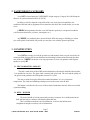
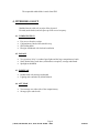
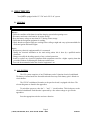
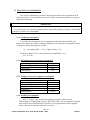
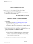
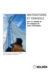
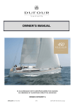
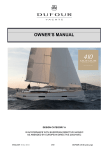
1
OWNER’S MANUAL
This manual is specifically intended for J 80 N° FR – JBE 80_____________
It should always be kept on board.
INTRODUCTION
Welcome aboard and to the family of " J " owners.
J EUROPE is pleased to give you this manual that will help you to get to know your boat
better.
This manual is designed to help you get the maximum pleasure from your boat in total safety.
It contains details of the boat, the equipment supplied and fitted, the installations and instructions
on its use and maintenance. Read it through carefully and familiarise yourself with your boat before
you set sail.
If this is your first boat or if you are changing to an unfamiliar type of boat, please ensure, for
your comfort and safety, that you have experience of handling and using it before taking over
command. Your dealer, your national sailing association or your local sailing club will be very
pleased to advise you on sailing schools and skilled instructors in your area.
PLEASE KEEP THIS MANUAL IN A SAFE PLACE AND PASS IT ON
TO THE NEW OWNER IF YOU SHOULD SELL THE YACHT.
Page 2
J EUROPE, Parc Actilonne, BP 56, 85340 Olonne Sur Mer – France
24-mai-05
CONTENTS
Page
1. TECHNICAL CHARACTERISTICS...................................................................................................6
2. YACHT DESIGN CATEGORY...........................................................................................................7
3. CONSTRUCTION................................................................................................................................7
3.1. THE COMPOSITE LAMINATE ..................................................................................................7
3.2. KEEL - RUDDER..........................................................................................................................7
4. INTERIOR LAYOUT...........................................................................................................................8
4.1. COMPANIONWAY ......................................................................................................................8
4.2. SALOON .......................................................................................................................................8
4.3. FOREPEAK ...................................................................................................................................8
4.4. AFT PEAK.....................................................................................................................................8
5. ELECTRICITY.....................................................................................................................................9
5.1. GENERAL .....................................................................................................................................9
5.2. 12 V SYSTEM ...............................................................................................................................9
5.3. ELECTRICAL CONSUMPTION ...............................................................................................10
5.3.1. Calculating consumption ......................................................................................................10
5.3.2. Maximum electrical equipment consumption.......................................................................10
5.3.3. Examples of electrical equipment consumption ...................................................................10
5.3.4. Installing new equipment......................................................................................................10
6. MECHANICAL SYSTEM .................................................................................................................11
6.1. GENERAL ...................................................................................................................................11
6.2. SAFETY.......................................................................................................................................11
7. FLOODING / BAILING.....................................................................................................................11
8. FIRE PROTECTION ..........................................................................................................................12
8.1. CHARACTERISTICS .................................................................................................................12
8.2. SAFETY INSTRUCTIONS.........................................................................................................12
9. SAILS AND RIGGING ......................................................................................................................13
9.1. RIGGING.....................................................................................................................................13
9.2. GENOA FURLING SYSTEM.....................................................................................................13
9.3. SAILS...........................................................................................................................................13
9.3.1. Breaking in............................................................................................................................13
9.3.2. Tensioning.............................................................................................................................13
9.3.3. Furling and maintenance.......................................................................................................13
9.3.4. The spinnaker (option)..........................................................................................................14
9.3.5. Setting the sails .....................................................................................................................14
9.4. RUNNING RIGGING .................................................................................................................15
10. DECK FITTINGS .............................................................................................................................15
10.1. MAINTENANCE ......................................................................................................................15
10.2. INSTALLING ADDITIONAL DECK FITTINGS ...................................................................16
11. MAINTENANCE OF THE UNDERBODY ....................................................................................16
11.1. PROTECTION...........................................................................................................................16
11.1.1. The hull ...............................................................................................................................16
11.1.2. The ballast...........................................................................................................................17
11.2. SCRUBBING.............................................................................................................................17
12. MAINTENANCE OF TOPSIDES....................................................................................................17
Page 3
J EUROPE, Parc Actilonne, BP 56, 85340 Olonne Sur Mer – France
24-mai-05
12.1. Maintaining the TOPSIDES and the deck .................................................................................17
12.2. Repairs to the hull or the deck ...................................................................................................18
12.2.1. Light scratches : ..................................................................................................................18
12.2.2. Cracks in the gelcoat in smooth areas:................................................................................18
12.2.3. Cracks in the anti-skid surface............................................................................................18
12.2.4. Cracks affecting the laminate..............................................................................................18
12.3. Scratches TO the port-LIGHTS .................................................................................................18
13. LIGHTNING PROTECTION...........................................................................................................19
13.1. Protecting people during a storm ...............................................................................................19
13.2. Following a lightning strike .......................................................................................................19
14. PROTECTING THE ENVIRONMENT & SAFETY.......................................................................19
15. SAFETY EQUIPMENT ...................................................................................................................20
16. LIFTING, HAULING OUT..............................................................................................................20
17. WARRANTY....................................................................................................................................21
TABLE OF APPENDICES
Page
DECK PLAN ................................................................................................................................ A2
SAIL PLAN .................................................................................................................................. A3
RUNNING RIGGING .................................................................................................................. A4
ELECTRICAL DIAGRAM .......................................................................................................... A5
Page 4
J EUROPE, Parc Actilonne, BP 56, 85340 Olonne Sur Mer – France
24-mai-05
Local J EUROPE dealer
NAME
:
_________________________________________________
ADDRESS
:
_________________________________________________
_________________________________________________
_________________________________________________
TEL
:
_________________________________________________
FAX
:
_________________________________________________
This is our local representative who can provide all the necessary assistance and answer all
your questions. He can also guide and advise you on the technical checks for commissioning your
boat and on how to maintain it.
As soon as you receive your owner’s manual date and sign the receipt below and return it within 8
days to J EUROPE, to be covered by our warranty. The warranty is not valid unless the receipt is
returned to the manufacturer on time. If not, the delivery date will be taken into account as
departure for the warranty (Conditions of the warranty page 21).
CERTIFICATE OF WARRANTY
I, undersigned,
Name
Address
Country
………………………………………………
………………………………………………
………………………………………………
………………………………………………
………………………………………………
………………………………………………
Owner of J 80 N° FR-JBE80……………………….
declare that I have received the owner’s manual, including the declaration of conformity with the
registered tonnage of a standard production yacht and the declaration of CE approval.
The vessel has been delivered complete and in good condition.
This vessel is covered by the warranty conditions detailed on page 21 of the owner’s manual.
This warranty commences from …………………………, the date of delivery of my vessel.
Date …………………….
Signature :
Page 5
J EUROPE, Parc Actilonne, BP 56, 85340 Olonne Sur Mer – France
24-mai-05
1. TECHNICAL CHARACTERISTICS
Design category : B
Certificat N° A JCF 980112 V
Length of hull :
Length waterline :
Maximum beam :
8.00 m
6.70 m
2.50 m
Draught (light) :
Air draught
1.50 m
11.4 m
Weight of ballast :
Displacement (light) :
Maximum permitted load :
675 kg
1450 kg
950 kg
Tonnage (for customs purposes) :
3.83 Tx
Number of persons allowed according to category :
A
0
B
5
C
8
D
8
Mainsail area :
Medium genoa area:
Solent jib area :
Storm jib area
I:
J:
P:
E:
21.0 m²
20.2 m²
14.0 m²
3.0 m²
9.60 m
2.90 m
9.14 m
3.81 m
Outboard engine: …..……….
Maximum permitted power :
………………. N°…………………………..
4,5 kW
Service battery :
12 V 1 x 55 A
Wetted surface area :
approx. 10 m²
Mast :
Boom :
Furling system :
RDM Sparcraft extrusion IMS 80
RDM Sparcraft extrusion F 60
Harken unit 00
Page 6
J EUROPE, Parc Actilonne, BP 56, 85340 Olonne Sur Mer – France
24-mai-05
2. YACHT DESIGN CATEGORY
Your J 80 is classed under the "OFFSHORE" design category (Category B) of the European
directive for yacht construction (Ref. 95/25/CE).
Its ability to sail also depends on the skills of the crew, their physical capabilities, the
condition of the boat and its equipment. Please therefore take these into account before you set out
to sea.
J EUROPE cannot guarantee that the vessel will function perfectly in exceptional conditions
(violent storms, hurricanes, cyclones, waterspouts, etc.).
At J EUROPE , our craftsmen have devoted all their skills and energy to building you a boat
you can be proud of and which will provide you and your crew with the greatest enjoyment.
3. CONSTRUCTION
Your J 80 has not only received the greatest care and attention from everyone involved in its
construction but also benefits from architectural and technological innovations that make this boat
state of the art. J EUROPE has drawn on its long experience to select only products of the highest
quality for your J 80.
3.1. THE COMPOSITE LAMINATE
The hull is made from a balsa-GRP sandwich laminate with uniaxial and bidirectional cloths.
It is moulded in one piece. The glass cloth is entirely laid up by hand. The resin and the quality of
the gelcoat used guarantees the hull against osmosis for 5 years.
The deck is made from a glass fibre-balsa sandwich laminate. It is very resistant to
compression. The cloths and moulding techniques used are the same as for the hull.
The bottom is reinforced with a series of floor frames laminated to the hull, then covered with
a partial moulding.
3.2. KEEL - RUDDER
The keel with bulb is in lead protected by an epoxy treatment. Its is solidly bolted to the
hull, with the help of a stainless steel backing plate and nuts.
This is installed towards the end of construction, as soon as the hull has been
strengthened enough to avoid any risk of deformation.
Page 7
J EUROPE, Parc Actilonne, BP 56, 85340 Olonne Sur Mer – France
24-mai-05
The suspended rudder blade is made from GRP.
4. INTERIOR LAYOUT
Moulded interior with sole in stripe effect plywood.
Forward (under berths) and aft spaces provide reserve buoyancy.
4.1. COMPANIONWAY
•
•
•
•
Easy access from the cockpit
Companionway fitted with removable step
GRP sliding hatch
Plexiglas washboard with lock and ventilation
4.2. SALOON
•
•
•
Very spacious, lit by 2 coachroof port-lights and the large companionway hatch.
Settee berths facing each other (with mattress on option), stowage underneath.
Spotlight on bulkhead
4.3. FOREPEAK
•
•
Double berth with stowage underneath
Lighting and ventilation by 420x420 hatch
4.4. AFT PEAK
•
•
Vast stowage area either side of the companionway.
Stowage space under berth.
Page 8
J EUROPE, Parc Actilonne, BP 56, 85340 Olonne Sur Mer – France
24-mai-05
5. ELECTRICITY
Your J 80 is equipped with a 12 V DC and a 230 V AC system.
5.1. GENERAL
IMPORTANT
Always :
& Check the condition of the batteries and the charging system before putting to sea.
& Disconnect and remove the batteries for winter storage.
& Keep the battery voltage at more than 10.5V during winter storage.
& Check that the navigation equipment is working.
& Check that the navigation lights are working before sailing at night and carry replacement bulbs for
all the navigation and internal lights.
Never :
' Work on any electrical equipment while it is connected.
' Modify the electrical installation or the main wiring unless this is done by a qualified marine
electrician.
' Change or modify the breaking capacity of any overload protection.
' Install or replace any electrical equipment with components rated for a higher capacity than that
prescribed without recalibrating the conductors and the fuses.
' Leave the boat unattended when the electrical equipment is on.
5.2. 12 V SYSTEM
The 12V system comprises of one 55Ah battery and a 3 function electrical switchboard.
The battery is located under the forward berth at the mast step. Each battery pole is linked to a
circuit breaker.
The 12V DC switchboard, located over the port fore berth, is equipped with fuses. The
relevant diagrams are found in the appendices.
To switch the system on, close the " + " and " - " circuit breakers. This feeds power to the
electrical switchboard. Each function is protected by a fuse whose ratings are given in the
appendices.
Press the appropriate switch to activate a function.
Page 9
J EUROPE, Parc Actilonne, BP 56, 85340 Olonne Sur Mer – France
24-mai-05
5.3. ELECTRICAL CONSUMPTION
The capacity of the batteries has been designed to provide the power requirement of all
onboard accessories. To avoid problems, however, always ensure that the batteries are properly
charged and maintained.
IMPORTANT
If you install any new electrical equipment, please ensure that the battery capacity is still suitable
for the new overall level of consumption.
5.3.1. Calculating consumption
To calculate the consumption of your equipment and determine how much life your
batteries have before they require recharging, multiply the consumption by the number of items
of equipment and the operating time in hours.
e.g. : 1 navigation light
2 Ah x 1 light x 3 hours = 6A
The battery output is 70% so the result must be multiplied by 1.4, i.e. :
6 x 1.4 = 8.4A.
5.3.2. Maximum electrical equipment consumption
Type of equipment
Two-colour light
Interior light
Electric pump
Consumption
1.8A
0.8A
3.5A
5.3.3. Examples of electrical equipment consumption
Type of equipment_
VHF radio telephone in standby mode
VHF radio telephone transmitting
Log speedo
Anemometer
Automatic pilot
Consumption
1A
5A
0.1A
0.1A
1 to 3A
5.3.4. Installing new equipment
Since 1st January 1996, all electrical equipment is subject to the European
"Electromagnetic Compatibility'' directive (Ref 89/336/CEE). Any new equipment installed
must conform to this standard and be CE marked. The equipment must also be supplied
with a certificate of conformity and a user’s manual.
Page 10
J EUROPE, Parc Actilonne, BP 56, 85340 Olonne Sur Mer – France
24-mai-05
Please contact your dealer about installing such equipment or carefully follow the
installation instructions (particularly the sections on wiring and system protection).
6. MECHANICAL SYSTEM
6.1. GENERAL
Your J 80 is fitted with an outboard bracket on the transom for the fitting of an outboard long
shaft engine of 15kW maximum power.
6.2. SAFETY
BE CAREFUL !
Match the speed of your boat to the surrounding conditions in all situations, leaving a margin of safety.
Pay particular attention to :
• The sea conditions, currents and the force of the wind.
• Traffic.
• Manoeuvring in port.
• Passing through moorings.
• The stowage of the fuel tank.
7. FLOODING / BAILING
The J 80 has a bilge pump allowing the boat to be bailed. This manual bilge pump, located in
the cockpit, draws water from the sump under the saloon sole.
Read the instructions for the pumps carefully, especially the maintenance instructions.
ATTENTION
To reduce the risk of water flooding the boat :
& Close the deck hatches and the port-lights before sailing.
& Close the plumbing sea-cocks when sailing.
& Periodically check:
- the seals on the sea-cocks, valves and plumbing.
- that the cockpit drains are flowing freely.
- the seals on the rudder bearing.
Page 11
J EUROPE, Parc Actilonne, BP 56, 85340 Olonne Sur Mer – France
24-mai-05
8. FIRE PROTECTION
8.1. CHARACTERISTICS
Your J 80 should be equipped with at least 1 fire extinguisher located near the
companionway. The capacity should be minimum 5A/34B. The emergency exit is the
companionway.
8.2. SAFETY INSTRUCTIONS
IMPORTANT
It is the boat owner’s or captain’s responsibility to :
& Check the fire extinguishing equipment in accordance with the manufacturer’s instructions.
& Replace any out of date or used fire extinguishing equipment with equipment of similar or of higher
capacity.
& Ensure that the fire extinguishing equipment is readily accessible when the boat is occupied
& Instruct every member of the crew regarding:
• the location and operation of the fire extinguishing equipment
• the location of the emergency exits
ATTENTION
Always :
& Keep the bilges clean and regularly check for the build up of fuel vapour or gas
& Only replace items of fire extinguishing equipment with similar equipment of the same description,
technical capacity and fire resistance
Never :
' Obstruct access to the emergency exit.
' Obstruct access to safety controls.
' Obstruct lockers housing fire extinguishers.
' Leave the boat unoccupied with a gas appliance on.
' Use gas lamps in the boat.
' Refill the fuel tank when the engine is running.
' Smoke when handling fuel or gas.
ATTENTION
& CO2 extinguishers should only be used for electrical fires.
Page 12
J EUROPE, Parc Actilonne, BP 56, 85340 Olonne Sur Mer – France
24-mai-05
9. SAILS AND RIGGING
9.1. RIGGING
The mast is an essential part of your yacht : it is well dimensioned and well provided with
stays. You must, however, tension it correctly and regularly check the condition of the mast and
standing rigging. Carefully read the mast manufacturer’s instructions.
9.2. GENOA FURLING SYSTEM
Your J 80 is fitted with a Harken unit 00 furling system specially selected for its ease of
use, robustness and the quality of service provided by the manufacturer. Regularly check the
condition of the drum and the tubes. Follow the manufacturer's instructions.
9.3. SAILS
The sails are your yacht’s main source of propulsion. Take good care of them and they
will provide maximum power. They are very susceptible to friction wear. The synthetic fibres
can be damaged by chafing, particularly on the seams.
Mark any places where there is a risk of chafing and protect them. Do not let your sails
flap because this can break the fibres inside the sails.
9.3.1. Breaking in
It is very important to break in your sails. In fact, they will take their proper shape and
the threads in the seams will stretch to their final position under their initial load. Your sails
will only keep their good appearance and provide good service if they are properly broken in.
9.3.2. Tensioning
You must apply equal tension to the sail in all directions (luff, leech and foot)
For a headsail, the more you harden the sheet, the more you have to tighten the luff.
For a mainsail, the more tension on the leech, the more you have to tighten the foot and
the halyard.
9.3.3. Furling and maintenance
You should always take time to furl your sails carefully. How they are folded is very
important, even at sea.
Page 13
J EUROPE, Parc Actilonne, BP 56, 85340 Olonne Sur Mer – France
24-mai-05
If the sails are wet with seawater, rinse them thoroughly with freshwater and allow
them to dry before folding them. They should be flaked along the seam and then rolled
from the clew.
If the sails are to be permanently rigged, we recommend that you protect them from
UV rays and the weather (the furling genoa with a protective UV strip or a cover, the
mainsail with a cover).
Never use acetone or soda to clean the sails.
9.3.4. The spinnaker (option)
The J80 is designed to fly an asymmetrical spinnaker. est prévu pour être équipé d'un
spi asymétrique. It must be carefully packed before use to avoid tangling. Remember to
fully extend your bowsprit before hoisting the spinnaker
Leave the genoa in place when setting the spinnaker, then furl it once the spinnaker is
set. In the same way, unfurl the genoa before handing the spinnaker.
9.3.5. Setting the sails
The following table provides an idea of which sails to set according to the wind
conditions but factors other than the wind must also be borne in mind:
• The sea state.
• The comfort and capacity of the crew.
• Entering and leaving port, proximity to danger.
• Expectation of heavy weather or fog.
WIND
SAILS
Beaufort
Main
Scale
0 to 2
Genoa
Main
2 to 3
Genoa
Main
3 to 4
Genoa
Main
4 to 5
Genoa
GV
5 to 6
Genoa
Main
7 to 8
Genoa
Above
BEATING
REACHING
RUNNING
Full
BROAD
REACHING
Full
Full
Full
Full
Full or spi
Full
Full or spi
Full
Full or spi
Full
Full
Full
Full or spi
Full
Full or spi
Full
Full or spi
Full
Full or spi
1 reef
Mark 1or spi
1 reef
Mark 1 or spi
Full
Mark 1 or spi
Full
Mark 1
2 ris
Mark 1
2 ris
Mark 1 or spi
1 ris
Mark 1 or spi
1 ris
Mark 1
2 reefs
Mark 1
2 reefs
Mark 1 or 2
2 reefs
Mark 1 or 2
2 reefs
Storm jib
Storm jib
Storm jib
Storm jib or mark
3
REMAIN
IN
PORT
Full
Page 14
J EUROPE, Parc Actilonne, BP 56, 85340 Olonne Sur Mer – France
24-mai-05
9.4. RUNNING RIGGING
For the running rigging to retain its original qualities as long as possible, you must rinse it
in freshwater. We recommend that you do not leave any rigging contaminated with seawater in
the sun because it will then rapidly deteriorate.
Maintenance :
• Whenever possible, hang up the running rigging to avoid it lying soaked in seawater.
• During winter storage, stow any rigging that can be removed from the deck in a locker. The
halyards can be replaced by messenger lines.
Description of standard running rigging :
1 Spectra main halyard
1 Spectra jib halyard
1 polyester spinnaker halyard
1 polyester bowsprit control line
2 polyester jib sheets
1 polyester spinnaker sheet
1 polyester tack line
2 polyester spinnaker barbers
1 polyester mainsheet
1 cotton mainsheet traveller line
1 sheathed cable strop
1 polyester reef line
1 polyester backstay control line
1 polyester boom vang tackle
1 sheathed cable boom vang strop
∅ mm
8
8
Lg m
22
19
8
8
8
8
8
6
8
8
4
8
6
6
4
23
7
8
36
13
4
17
7
0.4
12
18
10
1.5
10. DECK FITTINGS
J EUROPE has selected quality deck fittings for your J 80, installed on reinforcements
suitably dimensioned for the load. Regular rinsing of the deck and the external fittings with
freshwater will lengthen their service life.
The layouts for the deck fittings and the running rigging are provided in the appendices.
10.1. MAINTENANCE
The winches must be serviced at least once a month and before any major passage.
Page 15
J EUROPE, Parc Actilonne, BP 56, 85340 Olonne Sur Mer – France
24-mai-05
•
•
•
•
•
Remove the winch taking care to mark the position of the pawls.
Degrease it using an industrial product or diesel oil.
Rinse it in freshwater.
Dry it.
Lubricate it lightly and uniformly using a Teflon or silicon-based product.
The blocks consist of aluminium and stainless steel components. Electrolysis may cause
some specks of corrosion. To delay this process, rinse the pulleys frequently with freshwater
and lubricate them with a Teflon or silicon-based product.
Some specks of corrosion may appear on the stainless steel components. The quality of
the steel is not to blame; this is usually due to ferrous deposits or atmospheric agents. Do not
allow corrosion to take hold, however, rinse the components with freshwater and rub them
gently using a non-abrasive passivating polish.
10.2. INSTALLING ADDITIONAL DECK FITTINGS
You should not improvise when installing additional deck fittings. Several parameters
must be taken into account; the position of the component, any interference with other
components, internal access, load, etc… Please contact your dealer who is a marine
professional.
11. MAINTENANCE OF THE UNDERBODY
11.1. PROTECTION
You must regularly protect your hull under water with antifouling paint. This will protect
your hull against algae and barnacles that can damage the hull and considerably reduce the J 80’s
performance.
11.1.1. The hull
For extra osmosis protection of your underbody, we recommend the application of an epoxy
primer. Please contact your dealer or proceed as follows:
• Clean the hull with a degreasing agent to remove any remaining mould extraction wax.
• Mark out the area for painting with masking tape.
• Apply 2 coats of epoxy primer to the hull, then 2 coats of antifouling paint.
Page 16
J EUROPE, Parc Actilonne, BP 56, 85340 Olonne Sur Mer – France
24-mai-05
IMPORTANT
& Scrupulously observe the application instructions for the products you are using.
' Never cover the anode with antifouling paint
11.1.2. The ballast
The ballast of your J 80 is protected by an epoxy treatment
11.2. SCRUBBING
Scrubbing two or three times a year is preferable to once a year. This provides an
opportunity to check the condition of the sea-cocks, the valves, the rudder blade, the sail drive,
the anodes and the cleanliness of the engine raw water intake grill. You can employ a highpressure water jet not exceeding 60 bars provided that the nozzle is kept at least 50cm away
from the hull. Do not use a scraper, detergents or any solvent not recommended by your dealer.
12. MAINTENANCE OF TOPSIDES
The GRP composite requires little maintenance but it is useful to carry out a minimum of
work to keep your boat in its original condition.
Scrapes and cracks in the gelcoat do not affect the structural integrity of your boat in any way.
The gelcoat is not part of the structure but it is important to ensure that no water can penetrate the
laminate. You should therefore repair any cracks immediately. It is important to consult your dealer
if you suffer a major impact.
12.1. MAINTAINING THE TOPSIDES AND THE DECK
• Wash down your boat with freshwater after each trip to preserve its sheen.
• Preferably use a product specially designed for GRP for the hull and the deck or use
washing powder.
• Rinse thoroughly after each “washing”.
• Do not use abrasive detergents or acid.
Page 17
J EUROPE, Parc Actilonne, BP 56, 85340 Olonne Sur Mer – France
24-mai-05
12.2. REPAIRS TO THE HULL OR THE DECK
12.2.1. Light scratches :
• Sand down with water and No. 400 and then No. 600 wet and dry paper.
• Rinse thoroughly frequently.
• Shine with a gelcoat polish.
12.2.2. Cracks in the gelcoat in smooth areas:
• Clean and dry the damaged section.
• Catalyse it.
• Use a spatula to apply a little catalysed gelcoat of the same colour as the deck or the hull
(see your dealer).
• Cover the repair with polyamide film or adhesive paper.
• Remove the film when the repair is dry.
• Sand down with water and No. 400 and then No. 600 wet and dry paper.
• Rinse thoroughly frequently.
• Shine with a gelcoat polish.
12.2.3. Cracks in the anti-skid surface
Consult your dealer.
12.2.4. Cracks affecting the laminate
Consult your dealer.
12.3. SCRATCHES TO THE PORT-LIGHTS
• Rub down with a soft cloth or piece of cotton coated with a metal polish.
• If the scratches are deep, check with your dealer.
IMPORTANT
Never use solvents to clean deck hatches and port-lights.
Page 18
J EUROPE, Parc Actilonne, BP 56, 85340 Olonne Sur Mer – France
24-mai-05
13. LIGHTNING PROTECTION
Your J 80 is protected against lightning. The rigging is electrically earthed by means of a
chainplate and an earthing braid connecting it to the keel bolts. Safety precautions should however
be observed.
13.1. PROTECTING PEOPLE DURING A STORM
ATTENTION
The following advice should be followed during a storm:
& Remain inside the boat as much as possible.
& Do not go into the water or dangle your arms or legs in the water.
& While maintaining appropriate control of the vessel, do not touch any component connected to the
lightning conduction system, particularly in any way that would form a connection between any of
these components.
& Avoid contact with any of the metal components in the rigging, the spars, the external fittings and
the guardrails.
13.2. FOLLOWING A LIGHTNING STRIKE
If the vessel has been struck by lightning:
• The lightning conduction system must be inspected for material damage and to check the
integrity of the system and the continuity of its earth.
• The compasses and the electrical and electronic equipment must be inspected for any
damage or any change in calibration.
14. PROTECTING THE ENVIRONMENT & SAFETY
Most maintenance products, engine oils and fuels or similar hydrocarbon products are
harmful to the environment; they should only be disposed of in the appropriate places (please check
with the harbour master.
Page 19
J EUROPE, Parc Actilonne, BP 56, 85340 Olonne Sur Mer – France
24-mai-05
IMPORTANT
& Certain products also represent a risk to your own and others people’s safety; you should therefore
always follow their instructions for use.
& The products used should be labelled and stowed in an appropriate location on the vessel.
' Do not start the bilge pump if there is oil or fuel in the engine compartment; such products should
only be discharged at the locations prescribed by law.
' Do not use the boat’s toilet when in port.
' Store your rubbish bags for disposing when you return to port.
' Never throw anything into the sea.
15. SAFETY EQUIPMENT
There is as yet no common agreement within the European Community regarding compulsory
safety equipment. We can inform you, however, of the prevailing French regulations for vessels
with CE approval. Please contact your dealer.
16. LIFTING, HAULING OUT
Lifting should be carried out by professionals. Your J 80 is equipped with a lifting ring (at
the foot of the companionway. Your J/80 is equipped with a lifting bar (at the foot of the
companionway). When lifting, make sure that the owner-provided sling is correctly fixed to the
lifting bar with a large shackle. Keep two mooring lines tied to the boat (1 forward and 1 aft) to
stop the boat from turning around the sling during lifting. During lifting with the mast in place, you
should load the boat forward beforehand and make sure that the masthead is clear of the lifting
cable. Make fast the sling with a restraining rope between the mast and the sling so that the sling
doesn’t press on the companionway.
During transportation or hauling out, the keel should be well supported on its bulb supporting
most of the vessel’s weight.
The cradle pads should be positioned on the structural elements and only exert sufficient
pressure to maintain the vessel upright.
Take advantage of hauling out to inspect the hull and the transducers.
Page 20
J EUROPE, Parc Actilonne, BP 56, 85340 Olonne Sur Mer – France
24-mai-05
IMPORTANT
Precautions to take when hauling out the boat :
& Raise the log impeller.
& Check the mast and remember to check that the masthead cannot touch the cable or the crane.
& Stop your outboard engine before hauling out.
& Balance the boat before completely lifting out the boat.
& Remove the rudder.
' Do not remain abaord during lifting.
Sling
elingue
Restraining
line
bout
de retenue
17. WARRANTY
J EUROPE guarantees against any hidden defect that could render our products incapable of
sailing for the whole of the period prescribed by law. Any modification to our products and in
particular the installation of parts other than original parts immediately invalidates this warranty.
The hull underbody is guaranteed against osmosis for a period of 10 years.
All the equipment is covered by individual manufacturer’s warranties for 1 year.
This warranty allows the purchaser to obtain repair or replacement of any part recognised as
defective provided that the user has correctly carried out the necessary maintenance at the
prescribed intervals. This warranty does not cover transport and handling costs nor any other loss,
in particular through immobilisation.
Page 21
J EUROPE, Parc Actilonne, BP 56, 85340 Olonne Sur Mer – France
24-mai-05
ANNEXES
# 363
# 082
# 082
# 082
# 082
# 001
# 144
# 172
# 009
# 096
# 092
# 082
# 028
(ST option)
# 32.2 A
PLAN DE PONT / DECK PLAN
Page A2
J EUROPE, Parc Actilonne, BP 56, 85340 Olonne Sur Mer - France
désignation
Etai Rod
Galhauban Mono
Inter Mono
Bas-Hauban Mono
Pataras Mono
Patte D'oie Mono
d. (mm)
5
5
4
5
4
3
lg (m)
9,98
9,59
6,71
3,52
8,7
2,56
terminaisons
EO / EO dém.
ET* / RS
ET* / RS
ET / RS
EO / ECH cav 5
EO / ECH fixe
PLAN DE VOILURE / SAILS PLAN
I = 9.60
J = 2.90
P = 9.14
E = 3.81
J80
J EUROPE, Parc Actilonne, BP 56, 85340 Olonne Sur Mer - France
Page A3
GREEMENT COURANT / RUNNING RIGGING
# 030
# 224
# 226
# 009
# 299
# 028
# 292
# 292
# 228
# 084
# 082
# 082
Page A4
J EUROPE, Parc Actilonne, BP 56, 85340 Olonne Sur Mer - France
# 082
SCHEMA ELECTRIQUE / ELECTRICAL DIAGRAM
feu tête de mât
mast light
plafonnier
10A
tête de mât
10A
éclairage int.
10A
libre
cabin lignt
batterie
battery
+
-
+
Page A5
J EUROPE, Parc Actilonne, BP 56, 85340 Olonne Sur Mer - France