1
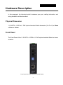
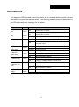
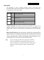
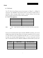
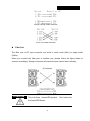
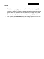
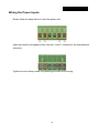
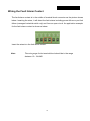
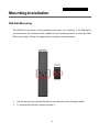
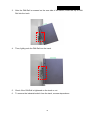
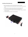
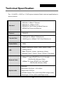
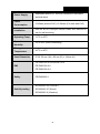
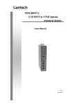
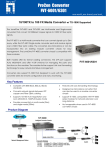
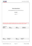
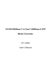
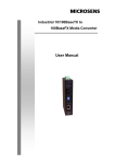
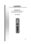
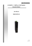
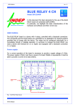
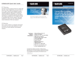
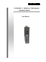
1 10/100TX + 1 100FX w/ 1 PoE Injector Industrial Switch User Manual CE Mark Warning This is a Class-A product. In a domestic environment this product may cause radio interference in which case the user may be required to take adequate measures. Content Introduction ................................................................ 1 Features ................................................................... 1 Package Contents.................................................... 2 Hardware Description ............................................... 3 Physical Dimension.................................................. 3 Front Panel .............................................................. 3 Top View .................................................................. 4 LED Indicators ......................................................... 5 DIP-Switch ............................................................... 6 Ports ......................................................................... 7 Cabling ..................................................................... 9 Wiring the Power Inputs ......................................... 10 Wiring the Fault Alarm Contact .............................. 11 Mounting Installation .............................................. 12 DIN-Rail Mounting.................................................. 12 Wall Mount Plate Mounting .................................... 14 Hardware Installation .............................................. 15 Installation Steps .................................................... 15 Network Application ................................................ 16 Troubleshooting ...................................................... 17 Technical Specification ........................................... 18 Introduction The 1 10/100TX + 100FX w/ 1 PoE Injector Industrial Switch is a cost-effective solution and meets the high reliability requirements demanded by industrial applications. Using fiber port can extend the connection distance that increases the network elasticity and performance. Besides, the industrial switch provides the PoE function for kinds of Powered Devices to receive power as well as data over the RJ-45 cable. Features System Interface/Performance RJ-45 ports support Auto MDI/MDI-X Function Embedded 1-port PoE Injection Store-and-Forward Switching Architecture Built-in Link Lose Forwarding Technology Power Supply DC 48V Redundant Power Overload Current Re-settable Fuse Present Case/Installation IP-30 Protection DIN Rail and Wall Mount Design Provides EFT protection 3,000 VDC for power line Supports 6,000 VDC Ethernet ESD protection 1 Package Contents Please refer to the package contents list below to verify them against the checklist. 1 10/100TX + 100FX w/ 1 PoE Injector Industrial Switch User manual Pluggable Terminal Block 2 wall mount plates with screws One DIN-Rail (attached on the switch) Compare the contents of the industrial switch with the standard checklist above. If any item is damaged or missing, please contact the local dealer for service. 2 Hardware Description In this paragraph, the Industrial switch’s hardware spec, port, cabling information, and wiring installation will be described. Physical Dimension 1 10/100TX + 100FX w/ 1 PoE Injector Industrial Switch dimension (W x D x H) is 30mm x 95mm x 140mm Front Panel The Front Panel of the 1 10/100TX + 100FX w/ 1 PoE Injector Industrial Switch is shown as below: Front Panel of the PoE Injectors Industrial Switch 3 Top View The top view of the 1 10/100TX + 100FX w/ 1 PoE Injector Industrial Switch has one terminal block connector of two DC power inputs. Top View of the PoE Injectors Industrial Switch 4 LED Indicators The diagnostic LEDs located on the front panel of the industrial switch provide real-time information of system and optional status. The following table provides the description of the LED status and their meanings for the switch. LED Color P1 Green P2 Green Fault FDX/COL (fiber port) LNK/ACT (fiber port) 100M (RJ-45) LNK/ACT (RJ45) FWD Red Yellow Green Yellow Green Green Description On Power input 1 is active Off Power input 1 is inactive On Power input 2 is active Off Power input 2 is inactive On Power input 1/2 or port connections failed Off Power input 1/2 and port connections are functional, or no power inputs On Full-duplex mode Flashing Collision occurs On Connected to network Flashing Networking is active Off Not connected to network On Linking to 100Mbps network Off Linking to 10Mbps network or disconnected On Connected to network Flashing Networking is active Off Not connected to network On The port is supplying power to the powered-device Off No powered-device attached or power supplying fails 5 DIP-Switch The DIP-Switch is used to configure operation mode for LLF (Link Lose Forwarding)/LFP (Link Fault Pass-Through), and operation mode for UTP/Fiber port. The default value of DIP-switch is OFF. S/W No 1 2 3 4 Status Description ON Enables Port/Power Alarm OFF Disable Port/Power Alarm ON Enables LLF/LFP OFF Disables LLF/LFP ON 100Base-FX Half-mode OFF 100Base-FX Full-mode ON Media mode (100TX to 100FX) OFF Switching mode LLF/LFP (DIP-Switch 2): Enabling LLF/LFP allows UTP/STP link failures to be reported to the fiber side and also allows Fiber link failures to be reported to the UTP/STP side. Therefore, a LLF/LFP feature is provided in both UTP/STP and Fiber side. Media mode (DIP-Switch 4): When media mode is enabled (ON), it operates with the minimum latency. The transmission flow does not wait until entire frame is ready, but instead it forwards the received data immediately after the data being received. And TP port should be forced at 100M in this application. When DIP-Switch is set in switching mode (OFF), the function is the same as a Switch/Hub. Note Please don’t change the DIP-switch setting when UTP/STP or fiber port is transmitting or receiving data. It may cause some data error. Besides, if you change the DIP-switch setting, please power off the switch and power on again to make the setting effective. 6 Ports RJ-45 ports The UTP (RJ-45) Fast Ethernet ports will auto-sense for 10Base-T or 100Base-TX connections. Auto MDI/MDIX means that the switch can connect to another switch or workstation without changing straight through or crossover cabling. See the below figures for straight through and crossover cable schematic. RJ-45 Pin Assignments Note Pin Number Assignment 1 Tx+ 2 Tx- 3 Rx+ 6 Rx- “+” and “-” signs represent the polarity of the wires that make up each wire pair. All ports on this industrial switch support automatic MDI/MDI-X operation, user can use straight-through cables (See figure below) for all network connections to PCs or servers, or to other switches or hubs. In straight-through cable, pins 1, 2, 3, and 6, at one end of the cable, are connected straight through to pins 1, 2, 3 and 6 at the other end of the cable. The table below shows the 10BASE-T/100BASE-TX MDI and MDI-X port pin outs. Pin MDI-X Signal Name MDI Signal Name 1 Receive Data plus (RD+) Transmit Data plus (TD+) 2 Receive Data minus (RD-) Transmit Data minus (TD-) 3 Transmit Data plus (TD+) Receive Data plus (RD+) 6 Transmit Data minus (TD-) Receive Data minus (RD-) 7 Straight Through Cable Schematic Cross Over Cable Schematic Fiber Port The fiber port of SC type connector can work in multi mode (2Km) or single mode (30Km). When you connect the fiber port to another one, please follow the figure below to connect accordingly. Wrong connection will cause the port cannot work normally. ATTENTION This is a Class 1 Laser/LED product. the Laser/LED Beam. 8 Don’t stare into Cabling Twisted-pair segment can be connected with unshielded twisted pair (UTP) or shielded twisted pair (STP) cable. The cable must comply with the IEEE 802.3u 100Base TX standard for Category 5. The cable between the converter and the link partner (switch, hub, workstation, etc.) must be less than 100 meters (328 ft.) long. Fiber segment using single-mode connector type must use 9/125µm single-mode fiber cable. User can connect two devices in the distance up to 30 Kilometers. Fiber segment using multi-mode connector type must use 50 or 62.5/125 µm multimode fiber cable. User can connect two devices up to 2Km distances. 9 Wiring the Power Inputs Please follow the steps below to insert the power wire. Insert the positive and negative wires into the V+ and V- contacts on the terminal block connector. Tighten the wire-clamp screws for preventing the wires from loosing. 10 Wiring the Fault Alarm Contact The fault alarm contact is in the middle of terminal block connector as the picture shows below. Inserting the wires, it will detect the fault status including power failure or port link failure (managed industrial switch only) and form an open circuit. An application example for the fault alarm contact is shown as below: Insert the wires into the fault alarm contact. Note The wire gauge for the terminal block should be in the range between 12~ 24 AWG. 11 Mounting Installation DIN-Rail Mounting The DIN-Rail is screwed on the industrial switch when out of factory. If the DIN-Rail is not screwed on the industrial switch, please see the following pictures to screw the DINRail on the switch. Follow the steps below to hang the industrial switch. 1. Use the screws to screw the DIN-Rail on the rear side of the industrial switch. 2. To remove the DIN-Rail, reverse the step 1. 12 3. After the DIN-Rail is screwed on the rear side of the switch, insert the top of DINRail into the track. 4. Then, lightly push the DIN-Rail into the track. 5. Check if the DIN-Rail is tightened on the track or not. 6. To remove the industrial switch from the track, reverse steps above. 13 Wall Mount Plate Mounting Follow the steps below to mount the industrial switch with wall mount plate. 1. Remove the DIN-Rail from the industrial switch; loose the screws to remove the DINRail. 2. Place the wall mount plate on the top & bottom side of the industrial switch. 3. Use the screws to screw the wall mount plate on the industrial switch. 4. Use the hook holes at the corners of the wall mount plate to hang the industrial switch on the wall. 5. To remove the wall mount plate, reverse steps above. 14 Hardware Installation In this paragraph, we are going to mention how to install the 1 10/100TX + 100FX w/ 1 PoE Injector Industrial Switch and the installation points to be attended to it. Installation Steps 1. Unpack the Industrial switch packing. 2. Check if the DIN-Rail is screwed on the Industrial switch or not. If the DIN-Rail is not screwed on the Industrial switch, please refer to DIN-Rail Mounting section for DINRail installation. If user want to wall mount the Industrial switch, then please refer to Wall Mount Plate Mounting section for wall mount plate installation. 3. To hang the Industrial switch on the DIN-Rail track or wall, please refer to the Mounting Installation section. 4. Power on the Industrial switch. Please refer to the Wiring the Power Inputs section for knowing the information about how to wire the power. The power LED on the Industrial switch will light up. Please refer to the LED Indicators section for indication of LED lights. 5. Prepare the twisted-pair, straight through Category 5e/above cable for Ethernet connection. 6. Insert one side of the RJ-45 cable into the Industrial switch Ethernet port and another side to the network device’s Ethernet port, e.g. Switch, PC or Server. The UTP/STP port (RJ-45) LED on the Industrial switch will light up when the cable is connected with the network device. Please refer to the LED Indicators section for LED light indication. 7. When all connections are set and LED lights all show in normal, the installation is complete. 15 Network Application This segment provides the sample to help the user have more actual idea of industrial switch application. For a sample application of the industrial switch, see the figure below. 16 Troubleshooting Verify that is using the right power cord/adapter (DC 48V), please don’t use the power adapter with DC output voltage higher than 48V, or it will burn this converter down. Select the proper UTP/STP cable to construct your network. Please check that is using the right cable. Use unshielded twisted-pair (UTP) or shield twisted-pair ( STP ) cable for RJ-45 connections: 100Ω Category 3, 4 or 5 cable for 10Mbps connections, 100Ω Category 5 cable for 100Mbps connections, or 100Ω Category 5e/above cable for 1000Mbps. Also be sure that the length of any twisted-pair connection does not exceed 100 meters (328 feet). Diagnosing LED Indicators: the Switch can be easily monitored through panel indicators, which describes common problems user may encounter and where user can find possible solutions, to assist in identifying problems. If the power indicator does not light on when the power cord is plugged in, user may have a problem with power cord. Then check for loose power connections, power losses or surges at power outlet. If you still cannot resolve the problem, contact the local dealer for assistance. If the Industrial switch LED indicators are normal and the connected cables are correct but the packets still cannot transmit. Please check your system’s Ethernet devices’ configuration or status. 17 Technical Specification The 1 10/100TX + 100FX w/ 1 PoE Injector Industrial Switch technical specifications is shown as below. IEEE 802.3 10Base-T Ethernet Standard IEEE 802.3u 100Base-TX/FX IEEE802.3x Flow Control and Back Pressure IEEE802.3af Power over Ethernet Protocol Transfer Rate Packet Buffer CSMA/CD 14,880 pps for 10Base-T Ethernet port 148,800 pps for 100Base-TX/FX Fast Ethernet port 1Mbits RJ-45: Link/Activity (Green), 100M (Yellow), Power LED Feeding (Green) Fiber: FDX/COL (Yellow), Link/Activity (Green) Per unit: Power 1 (Green), Power 2 (Green), Fault (Red) 10Base-T: 2-pair UTP/STP Cat. 3, 4, 5, 5e cable Network Cable EIA/TIA-568 100-ohm (100m) 100Base-TX: 2-pair UTP/STP Cat. 5/5E cable EIA/TIA-568 100-ohm (100m) Distance: Multi mode: 50/125μm ~ 62.5/125μm Optical cable Single mode: 9/125μm Available distance: 2km (multi-mode)/30km (single-mode) Wavelength: 1310nm (Multi-mode/Single-mode) 18 Power Supply Power Consumption Installation Operating Temp. Operation Humidity Storage Temperature Case Dimension Redundant power DC 48V with connective removable terminal block 3.3Watts (without PoE); 16.4Watts (Full load with PoE) DIN rail kit for DIN-type cabinet install and wall-mount ear for wall mounting -10oC to 60oC 5% to 95% (Non-condensing) -40oC to 85oC IP-30, 30 mm (W) x 95 mm (D) x 140mm (H) CE EN61000-4-2/3/4/5/6/8/11/12 EMI CE EN61000-6-2 CE EN61000-6-4 Safety CE/EN60950-1 IEC60068-2-32 (Free fall) Stability testing IEC60068-2-27 (Shock) IEC60068-2-6 (Vibration) 19