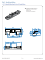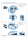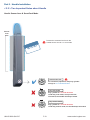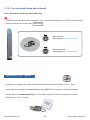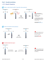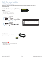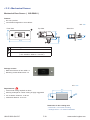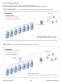
1
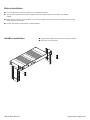
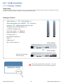
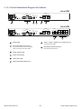
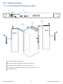
Integrated IT Access Control and Monitoring over Ethernet User Manual Infra-2200 / 2400 Cabinet SmartCard Handle, Network version Designed and manufactured by Austin Hughes UM-IS-2000-Q413V7 www.austin-hughes.com Legal Information First English printing, October 2002 Information in this document has been carefully checked for accuracy; however, no guarantee is given to the correctness of the contents. The information in this document is subject to change without notice. We are not liable for any injury or loss that results from the use of this equipment. Safety Instructions Please read all of these instructions carefully before you use the device. Save this manual for future reference. ■ ■ ■ ■ ■ ■ ■ ■ ■ ■ ■ Unplug equipment before cleaning. Don’t use liquid or spray detergent; use a moist cloth. Keep equipment away from excessive humidity and heat. Preferably, keep it in an air-conditioned environment with temperatures not exceeding 40º Celsius (104º Fahrenheit). When installing, place the equipment on a sturdy, level surface to prevent it from accidentally falling and causing damage to other equipment or injury to persons nearby. When the equipment is in an open position, do not cover, block or in any way obstruct the gap between it and the power supply. Proper air convection is necessary to keep it from overheating. Arrange the equipment’s power cord in such a way that others won’t trip or fall over it. If you are using a power cord that didn’t ship with the equipment, ensure that it is rated for the voltage and current labeled on the equipment’s electrical ratings label. The voltage rating on the cord should be higher than the one listed on the equipment’s ratings label. Observe all precautions and warnings attached to the equipment. If you don’t intend on using the equipment for a long time, disconnect it from the power outlet to prevent being damaged by transient over-voltage. Keep all liquids away from the equipment to minimize the risk of accidental spillage. Liquid spilled on to the power supply or on other hardware may cause damage, fire or electrical shock. Only qualified service personnel should open the chassis. Opening it yourself could damage the equipment and invalidate its warranty. If any part of the equipment becomes damaged or stops functioning, have it checked by qualified service personnel. What the warranty does not cover ■ ■ ■ Any product, on which the serial number has been defaced, modified or removed. Damage, deterioration or malfunction resulting from: Accident, misuse, neglect, fire, water, lightning, or other acts of nature, unauthorized product modification, or failure to follow instructions supplied with the product. Repair or attempted repair by anyone not authorized by us. Any damage of the product due to shipment. Removal or installation of the product. Causes external to the product, such as electric power fluctuation or failure. Use of supplies or parts not meeting our specifications. Normal wear and tear. Any other causes which does not relate to a product defect. Removal, installation, and set-up service charges. □ □ □ □ □ □ □ □ Regulatory Notices Federal Communications Commission (FCC) This equipment has been tested and found to comply with the limits for a Class B digital device, pursuant to Part 15 of the FCC rules. These limits are designed to provide reasonable protection against harmful interference in a residential installation. Any changes or modifications made to this equipment may void the user’s authority to operate this equipment. This equipment generates, uses, and can radiate radio frequency energy and, if not installed and used in accordance with the instructions, may cause harmful interference to radio communications. However, there is no guarantee that interference will not occur in a particular installation. If this equipment does cause harmful interference to radio or television reception, which can be determined by turning the equipment off and on, the user is encouraged to try to correct the interference by one or more of the following measures: ■ Re-position or relocate the receiving antenna. ■ Increase the separation between the equipment and receiver. ■ Connect the equipment into an outlet on a circuit different from that to which the receiver is connected. Notice : The changes or modifications not expressly approved by the party responsible for compliance could void the user’s authority to operate the equipment. IMPORTANT NOTE: To comply with the FCC RF exposure compliance requirements, no change to the antenna or the device is permitted. Any change to the antenna or the device could result in the device exceeding the RF exposure requirements and void user’s authority to operate the device. UM-IS-2000-Q413V7 www.austin-hughes.com Before Installation ■ ■ ■ ■ It is very important to locate the equipment in a suitable environment. The surface for placing and fixing the equipment should be stable and level or mounted into a suitable cabinet. Make sure the place has good ventilation, is out of direct sunlight, away from sources of excessive dust, dirt, heat, water, moisture and vibration. Position the equipment with respect to related facilities. ■ ■ InfraBox Installation Suggest the installation at the rear top mounting of cabinet M6 screws set not provided. er Pow r Doo r Rea tus Sta nt Fro ial Ser C t: VA Inpu 0 24 010 UM-IS-2000-Q413V7 www.austin-hughes.com Content Part I. InfraBox Installation < 1.1 > Package Contents P.1 < 1.2 > Overall Installation Diagram for Cabinet P.2 < 1.3 > Connection Diagram for Temp. sensor & PDU P.4 < 1.4 > Temp. & Himidity Sensor Connection & Specification P.5 < 1.5 > Cascade Connection P.6 Part II. Handle Installation < 2.1 > Handle Mounting Cut-out & Installation P.7 < 2.2 > Two Important Notes about Handle P.13 < 2.3 > Handle Operation P.15 Part III. Door Sensor Installation < 3.1 > Inductive Sensor < 3.2 > Mechanical Sensor P.16 P.18 Part IV. Network Setup < 4.1 > Daisy Chain < 4.2 > Star < 4.3 > Mixed P.20 P.20 P.21 Part V. Application < 5.1 > < 5.2 > < 5.3 > < 5.4 > Data Center Intelligent Building Remote Site Branches Part VI. Hardware Specifications UM-IS-2000-Q413V7 P.22 P.23 P.24 P.25 P.26 www.austin-hughes.com Content Part VII. IP Setup Utilities for InfraBox P.27 Part VIII. Software Installation & Activation < 8.1 > Hardware Requirement < 8.2 > Software Installation < 8.3 > Software Activation P.28 P.29 P.34 Part IX. Setup & Operation < 9.1 > < 9.2 > < 9.3 > < 9.4 > < 9.5 > < 9.6 > Legend Definition Cabinet Setup & Configuration User Setup & Configuration Card Assignment Monitoring & Control of Cabinet Log Record & Report P.36 P.36 P.41 P.44 P.45 P.45 Part X. General System Setup < 10.1 > < 10.2 > < 10.3 > < 10.4 > Floor Plan Background / Warning / Temperature Unit Database Management Services Setup ( Software SNMP / Email ) Time Zone / Time Rule P.46 P.47 P.48 P.49 Part XI. Backup & Restore P.51 Part XII. FAQ P.53 Part XIII. Troubleshooting P.54 Part XIV. Optional Acccessories P.55 UM-IS-2000-Q413V7 www.austin-hughes.com Part I. InfraBox Installation < 1.1 > Package Contents Unpacking The equipment comes with the standard parts shown on the package contents. Check and make sure they are included and in good condition. If anything is missing, or damage, contact the supplier immediately. Package Content - 2200 LAN Box x 1 OR 2400 LAN Box x 1 - Smart card handle, pair ( MiFARE OR Proximity ) - Inductive OR Mechanical Door Sensor, pair - Temperature & Humidity Sensor x 2 ( for 2400 LAN Box only ) - Front door cable x 1 ( 3425mm ) - Rear door cable x 1 ( 2625mm ) - 6’ Power cord x 1 - Activated SmartCard x 1 - Key x 1 - Cable clip x 8 - M5 x 12mm screw x 6 2200 LAN Box OR 2400 LAN Box Patented and Worldwide Patents Pending Each package bundled with smartcard x 1. The card on the bottom right shows card number information : Card# 12345678 Card# 12 UM-IS-2000-Q413V7 P.1 www.austin-hughes.com < 1.2 > Overall Installation Diagram for Cabinet Infra-2200 LAN Door Front Rear Power LED In Act In Out Status 1 2 3 Out Reset 4 5 6 Infra-2400 LAN Door Front Rear Power LED Status In Out Temp. Front Rear 1 3 5 7 2 4 6 8 Reset Act In Out 7 8 1 Power Input 7 Temp. / Temp. + Humid. RJ11 sensor port x 2 Connect sensor cable 2 Door cable DB-9 connector x 2 Connect to the front and rear handle via 2 pcs of all-in-one door cable 8 PDU RJ45 connection port x 8 Up to PDU connection x 8 3 Power & status LED 4 Power Reset button 5 “Act in Out” LED 6 Daisy chain RJ45 LAN port x 2 UM-IS-2000-Q413V7 P.2 www.austin-hughes.com Part I. InfraBox Installation < 1.2 > Overall Installation Diagram for cabinet Door Power Front Rear Power Reset Act In Out Status Joint connector >>>>> InfraBox >>>>>>> 4 2 >>>>>>> Joint connector 4 3 Rear Door 1 2 Front Door 1 2 5 1 HV-600 SmartCard handle x 2 2 Front door cable ( 3425mm ) with joint connector x 1 3 Rear door cable ( 2625mm ) with joint connector x 1 4 Door sensor ( attached with door cable in the joint point ) x 2 5 6’ power cord x 1 UM-IS-2000-Q413V7 P.3 www.austin-hughes.com < 1.3 > Connection Diagram for Temp. sensor & PDU Door Power Front Temp. port x2 Rear Power Reset PDU port x8 1 3 5 7 2 4 6 8 Act In Out Status TH SENSOR T / TH sensor with 2m cord TH SENSOR Cat5/6 cable up to 20m Up to PDU connection x 8 Each PDU connection via Cat5/6 cable up to 20m Connect to the LINK port of PDU meter MT & MTS compatible OU T IN CU RR 22 5 EN T (A ) ON DIP 1 2 3 4 RE DIP Switch <ON> LINK 5 6 7 8 SET OUT CURRENT (A) DIP Switch <OFF> 225 ON Dip switch setting : DIP >>>> 1 2 3 4 5 6 7 8 1 On PDU Dip switch no. 2 3 4 On On On 8 Off RESET UM-IS-2000-Q413V7 P.4 www.austin-hughes.com Part I. InfraBox Installation < 1.4 > Temp. & Humidity Sensor Connection & Specification Temp. & Humid. Sensor Part no. Temperature Sensitivity IG - TH01 Range 0 to 80°C ( 32 to 176°F ) Accuracy ±1.0°C typical ( ±2°F ) 0.1°C ( 0.2°F ) Resolution Response Time Relative Humidity Sensitivity 5 to 30 sec Range 0 to 100% R.H Accuracy 0 to 100, ±8.0% R.H 20 to 80, ±4.5% R.H. Resolution 1% R.H. Response Time Power Requirement Housing Voltage 8 sec 12VDC, powered by sensor port 20mA Current Consumption Power consumption 0.24 Watt Power on indicator Red LED Chassis & Cover plastic Color Installation Cable Cable Length Dark gray Magnetic base for unrestricted installation TH sensor w/ 2m cable ( standard ) TH sensor w/ 4m cable ( option ) Cable Specification 4-wired 3.5mm to RJ11 Cable Color Environmental Black Operating 0 to 80°C Degree Storage -5 to 80°C Degree Humidity 0~100%, non-condensing Dimensions Product 30L x 25Wx 18H mm Weight Net Compatibility InfraPower 10g W / WS / Wi / WSi series PDU X-2000 series InfraSolution InfraGuard UM-IS-2000-Q413V7 Cabinet sensor system P.5 www.austin-hughes.com < 1.5 > Cascade Connection LAN Power Reset 1 3 5 7 2 4 6 8 Act In Out Infra-2400 In Status Out Cascade LAN Power Reset Act In Out Infra-2200 In Status Out Cascade 1 3 5 7 2 4 6 8 LAN Power Reset Act In Out Infra-2400 In Status Out Cascade LAN Power Reset Act In Out Infra-2200 In Status Out The total length of a single daisy chain is 100m max. The total Infrabox of a single daisy chain is 50 boxes max. UM-IS-2000-Q413V7 P.6 www.austin-hughes.com Part II. Handle Installation < 2.1 > Handle Mounting Cut-out & Installation Custom Mounting Cut-out on Cabinet Door for Handle Installation : It is highly important to make a correct handle mounting cut-out on cabinet door. Please 100% follow the diagram on the below to make the cut-out. Unit : mm Cabinet >>>>> door UM-IS-2000-Q413V7 P.7 www.austin-hughes.com < 2.1 > Handle Mounting Cut-out & Installation Side View Close Side View Open 54° 273 Unit : mm 36 HV-600 handle design supports left side & right side open UM-IS-2000-Q413V7 P.8 www.austin-hughes.com Part II. Handle Installation < 2.1 > Handle Mounting Cut-out & Installation Handle Installation Steps 1. Mount HV-600 handle to the custom handle mounting cut-out position. 2. Insert the bundled M5 x 12mm screw x 3 pcs to secure the handle in place. M5 x 12mm screw While insert the screws to secure the handle with electronic screwdriver, please set the torque NOT exceed 8 kgf/cm UM-IS-2000-Q413V7 P.9 www.austin-hughes.com < 2.1 > Handle Mounting Cut-out & Installation Parts of Cabinet Door Locking Bar Three parts available for cabinet manufacturer 3 to produce the cabinet door locking bar system integrated with HV-600 handle . 2 1 Locking bar handle bracket, pc Order part no. : 404 - 8 - 02111 material : alloy ( fixing screw not provided ) >>>>> Dimension Diagram on next page 2 Locking Bar 1 3 2 Locking bar retaining bracket, pc Order part no. : 314 - 0 - 10010 material : alloy ( fixing screw not provided ) 2 Dimension Diagram on next page 3 Locking bar roller, pc Order part no. : 314 - 0 - 10020 material : alloy ( fixing screw not provided ) Dimension Diagram on next page 3 UM-IS-2000-Q413V7 P.10 2 www.austin-hughes.com Part II. Handle Installation < 2.1 > Handle Mounting Cut-out & Installation 1 Locking bar handle bracket, pc Order part no. : 404 - 8 - 02111 material : alloy ( fixing screw not provided ) UM-IS-2000-Q413V7 P.11 www.austin-hughes.com < 2.1 > Handle Mounting Cut-out & Installation 2 Locking bar retaining bracket, pc Order part no. : 314 - 0 - 10010 material : alloy ( fixing screw not provided ) 3 Locking bar roller, pc Order part no. : 314 - 0 - 10020 material : alloy ( fixing screw not provided ) UM-IS-2000-Q413V7 P.12 www.austin-hughes.com Part II. Handle Installation < 2.2 > Two Important Notes about Handle Handle Sensor Area & SmartCard Mode Sensor area Present the smartcard and touch the handle sensor area for 1 to 2 seconds Smartcard mode For smartcard operation, keep key cylinder always to 12 o’clock direction. Key lock mode Key cylinder to 9 o’clock direction Under key lock mode, even present the smartcard, the handle still keeps locked. Key unlock mode Key cylinder to 3 o’clock direction Under key unlock mode, the handle keeps unlocked. UM-IS-2000-Q413V7 P.13 www.austin-hughes.com < 2.2 > Two Important Notes about Handle Lock / Unlock the handle by mechanical key Unless the smartcard handle is defective, lock / unlock the handle by key is NOT recommended Please insert & turn the key with push force Key lock mode Key cylinder to 9 o’clock direction. Key unlock mode Key cylinder to 3 o’clock direction. Maintenance Key ( MK-001 ) Improper key usage may cause the cylinder stuck at abnormal direction 1 to 2 o’ clock. Under this circumstance, the maintenance key (MK-001) is required to solve the problem. Please insert the maintenance key to the cylinder with push force for turning it to normal direction 9 or 12 or 3 o’clock. UM-IS-2000-Q413V7 P.14 www.austin-hughes.com Part II. Handle Installation < 2.3 > Handle Operation How to unlock the handle & open the door properly Locked status in blue Unlocked status in red >>> Unlocked status in blue Flashing Once Within 5 seconds after smartcard detection, users should : - lift up the handle - open the door Door Opening ( within 5 seconds ) To avoid reckless collision, push the handle back to the park position properly after open the door. Over 5 seconds, the handle still keeps unlock. How to close the door properly Unlocked status in blue Locked status in blue Ensure the handle returns to park position properly once the door is closed. Over 5 seconds, the handle will auto-lock. Door Closing ( within 5 seconds ) Unauthorized door-open Locked status in blue NO Authenticated Smartcard Detection UM-IS-2000-Q413V7 Locked status in blue Door Opening improperly or by force P.15 If the door is opened improperly or by force, audio alarm ‘beep’ sound will be created immediately. www.austin-hughes.com Part III. Door Sensor Installation < 3.1 > Inductive Sensor Optional door sensor is an essential accessories as users can be alerted by visual and audio alarm for unauthorized access. Inductive Door Sensor, pair ( ISO-DSI-2 ) Features light weight / adhesive mini size ( 32.5 x 12.2 x 9.2 mm ) no custom cutting required on door Front View 12.2 mm 2 1 4 3 32.5 mm 9.2 mm Side View 1 Sensor area 2 Red LED ( light up while door opening ) 3 2m cable 4 Cable jack ( connect to handle ) 5 2mm adhesive tape 5 Package content Inductive sensor w/ 2m cable x 2 2mm adhesive tape x 6 Requirements cabinet frame made of ferrous metal ( iron ) sensing distance 3mm UM-IS-2000-Q413V7 P.16 www.austin-hughes.com Part III. Door Sensor Installation < 3.1 > Inductive Sensor Suggested sensor position Installation steps - connect to the handle - guide & fix the cable with cable clips ( bundle with handle package ) - place the sensor at the top of the door, close to the opening side - adjust the sensor with adhesive tape to ensure the sensing distance between door to frame within 3mm while door in close status Sensor Operation DOOR OPEN - open door - inductive sensor lose detection with cabinet frame - DOOR OPEN SIGNAL sends out DOOR CLOSE - close door - inductive sensor detects the cabinet frame - Red LED of sensor light up - DOOR CLOSE SIGNAL sends out Door frame Cabinet frame Door frame CLOSED Cabinet frame OPENED Sensing distance < 3mm UM-IS-2000-Q413V7 Sensing distance > 3mm P.17 www.austin-hughes.com < 3.2 > Mechanical Sensor Mechanical Door Sensor ( ISO-DSW-2 ) Features low cost / precise cost efficient integration to new cabinet unit : mm Front View Top View 1 Side View 15.0 3 11 7.3 22.5 2 15.75 6.5 52.0 9.25 3 1 Steel mounting plate with 2 screw holes 2 Cable connector 3 Press button ( total travel distance : 9.25 mm ) ( min. actuation distance : 3.00 mm ) Package content Mechanical sensor w/ 2m cable x 2 Mounting screws 6#32x4.5mm x 2 unit : mm Requirements 37.5 custom hole cutting required on doors 23 ordering a sample for custom cutting is highly suggested 2- 12.5 6.3 min. actuation distance : 3.00 mm total travel distance : 9.25 mm 3.5 Dimension of door cutting hole - circle hole x 2 for screw mounting - rectangle hole x 1 for sensor installation UM-IS-2000-Q413V7 P.18 www.austin-hughes.com Part III. Door Sensor Installation < 3.2 > Mechanical Sensor Suggested sensor position Installation steps - connect to the handle - place the sensor at the top middle of the door - install the sensor in the custom hole - secure it with bundled mounting screws 6#32x4.5mm x 2 Sensor Operation DOOR CLOSE - close door - Sensor button is pressed on DOOR OPEN - open door - Sensor button is released - DOOR CLOSE SIGNAL sends out - DOOR OPEN SIGNAL sends out Door frame Door frame Cabinet frame Cabinet frame OPENED CLOSED Button released Actuation distance > 3mm Physical touch required UM-IS-2000-Q413V7 P.19 www.austin-hughes.com Part IV. Network Setup InfraSolution provides 3 connection ways - Daisy Chain , Star , Mixed. Which connection users apply is related to the site scale, environment and users’ requirements. < 4.1 > Daisy Chain Connect all InfraBoxes by Cat5/6 cable, and no any network switch required Client PCs Key Benefits Simple connection No network switch required Appropriate for small networks Management PC Quantity of InfraBox / Cabinet : Up to 50 Total distance in daisy chain : Up to 100M < 4.2 > Star Connect to network switch by a point-to-point connection Key Benefits Appropriate for large networks Client PCs Increased fault tolerance Easy for troubleshooting Network Switch Management PC Network switch required Total distance for each InfraBox to Network Switch : Up to 100M UM-IS-2000-Q413V7 P.20 www.austin-hughes.com Part IV. Network Setup < 4.3 > Mixed Combining daisy chain with star connection Key Benefits Most effective and practical for large scale of networks Take all advantages of Daisy Chain and Star connection Flexible to meet a variety of network environments and needs Up to 50 in each row Client PCs Network Switch Management PC Up to 50 in each row Total InfraBox Qty in Mixed Network : Up to 800 UM-IS-2000-Q413V7 P.21 www.austin-hughes.com Part V. Application < 5.1 > Data Center By mixed connection, InfraSolution can be scalable up to 800 cabinets and the 2200 and 2400 InfraBoxes can be coexisted in the same network. Users are enabled to manage and remotely access all cabinets under a centralized and user friendly GUI. Connect the 1st InfraBox in each daisy chain to the network switch Connect the management PC and client PCs via the network switch Up to 800 Infraboxes / Cabinets Client PCs Network Switch Management PC UM-IS-2000-Q413V7 P.22 www.austin-hughes.com Part V. Application < 5.2 > Intelligent Building It is essential for a Multi-Storey Intelligent Building to be applied with a centralized management system for the building’s mechanical and electrical equipment such as security, power, ventilation, and lighting systems, etc. InfraSolution system allows equipment to be distributed throughout a building simply by deploying an Ethernet network. To keep capital costs down, InfraSolution can also be cascaded between boxes up to 100m over a Cat5/6 cable. Signal weakness problem for long distance between InfraBoxes can be solved by applying network hubs with repeater function. Setup Scenario in the whole Intelligent Building Connect the InfraSolution network in each floor via the network ethernet / fiber switch Up to 800 Infraboxes / Cabinets Daisy Chain Scenario (Up to 50) Daisy Chain Scenario (Up to 50) Backbone Network / Fiber Switch Star Connection Network Switch for Star / Mixed Connection (Up to 50) Star Connection (Up to 50) Mixed Connection (Up to 50) Mixed Connection Management PC (Up to 50) Control Room Client PCs UM-IS-2000-Q413V7 P.23 www.austin-hughes.com < 5.3 > Remote Site Besides data centers and intelligent buildings, InfraSolution can be also applied to the remote site for access and monitoring over IP anytime and anywhere. Optional IP Remote Box IS-101 with SSL security is available for the remote management over IP. InfraSolution Manager Software License is required for each remote site / management PC Headquarter Workstation Remote Box Remote Site A InfraSolution network Management PC Network Switch Network Switch Client PCs Remote Site B InfraSolution network UM-IS-2000-Q413V7 Management PC P.24 www.austin-hughes.com Part V. Application < 5.4 > Branches How to manage a number of branches by InfraSolution For a global or scalable company, it is vital to remote access and monitor the network of their nationwide and worldwide branches. InfraSolution provides an ideal solution to keep an eye on cabinet access security and environmental condition. InfraSolution Manager Software License is required for each remote site / management PC Headquarter Workstation Up to 50 in each row Branch A InfraSolution network IS-101 Remote Box IS-101 Remote Box Up to 50 in each row Branch B InfraSolution network Management PC IP remote access anywhere Up to 50 in each row Network Switch IS-101 Remote Box Branch C InfraSolution network UM-IS-2000-Q413V7 P.25 www.austin-hughes.com Part VI. Hardware Specifications Power Item 100~240VAC, 50 / 60Hz 0.5A via AC / DC cord Regulation Approval FCC, CE Casing Material Steel & aluminum, silver colour Operation 0˚ to 50˚C Degree -5˚ to 60 ˚C Degree Storage Environmental Relative Humidity Shock 90%, non-condensing 50G peak acceleration (11 ms, half-sine wave) Vibration 58~100Hz / 0.98G (11ms / cycle) Product ( W x D x H ) 410 x 135 x 39.7 mm 16.1 x 5.3 x 1.56 inch Packing ( W x D x H ) 557 x 367 x 98 mm 21.9 x 14.4 x 3.9 inch Dimension Weight Net 1.16 kg / 2.55 lbs Gross 2.3 kg / 5.06 lbs UM-IS-2000-Q413V7 P.26 www.austin-hughes.com Part VII. IP Setup Utilities for InfraBox After the completion of InfraBox connection, please take the following steps to configure the InfraBox : 1. Prepare a notebook computer to download the IP setup utilities for InfraBox from the following link: http://www.austin-hughes.com/support/utilities/infrasolution/InfraBoxSetup.msi 2. Double click the IP setup utilities for InfraBox.msi and follow the instruction to complete the installation. 3. Go to each InfraBox with the notebook computer & a piece of CAT. 5 / 6 cable to configure InfraBox as below. Please take the procedure for all InfraBoxes ONE BY ONE. CAT. 5 / 6 cable To notebook computer LAN port To InfraBox LAN port Write down the new IP address for Part IX - < 9.2 > Cabinet Setup & Configuration 4. Click “ Scan “ to search the connected InfraBox. 5. Change the desired IP address / Subnet mask / Gateway, then Click “ Save “ to confirm the setting of InfraBox. 6. The default IP address is as below: IP address: 138.168.1.20 Subnet mask: 255.255.0.0 Gateway: 138.168.1.1 UM-IS-2000-Q413V7 P.27 www.austin-hughes.com Part VIII. Software Installation & Activation < 8.1 > Hardware Requirements Please prepare a dedicated management PC with the hardware requirements as below for InfraSolution Manager - Martix Server Recommended hardware : For node 1 to 100 : - Processor : - Memory : - Available Disk Space : - Optical drive : - LAN Card : - Display : Intel® Core™ i5 Processors 2.3GHz or above Min. 4GB Ram Min. 500GB SATA DVD-ROM Drive 100/1000Base-T NIC Monitor with 1024 x 748 or higher resolution For node over 100 : - Processor : - Memory : - Available Disk Space : - Optical drive : - LAN Card : - Display : Dual CPU Intel® Xeon® Processor 5500 or 5600 Series or above Min. 8GB Ram Min. 1TB SATA DVD-ROM Drive 100/1000Base-T NIC Monitor with 1024 x 768 or higher resolution Supported OS platform list : - MS Windows 7 Professional with SP1 - MS Windows 7 Ultimate with SP1 - MS Windows Server 2003 R2 Standard Edition with SP2 - MS Windows Server 2008 Standard Edition with SP2 - MS Windows Server 2008 R2 Standard Edition with SP1 UM-IS-2000-Q413V7 P.28 www.austin-hughes.com Part VIII. Software Installation & Activation < 8.2 > Software Installation After the InfraBox installation, please take the following steps to install the InfraSolution Manager - Matrix Server 1. Download the InfraSolution Manager - Matrix Server to the management PC from the link : http://www.austin-hughes.com/support/software/infrasolution/InfraSolution Manager.msi 2. Turn off “ UAC Setting “ Please visit the following link for the setting http://windows.microsoft.com/en-gb/windows7/turn-user-account-control-on-or-off 3. Restart Management PC Ensure users login the management PC as a member of “ Administrators “ Group before InfraSolution Manager installation and execution 4. Double click the InfraSolution Manager.msi and follow the instruction to complete the installation. click “ Next ” click “ Install ” click “ Finish ” Complete UM-IS-2000-Q413V7 P.29 www.austin-hughes.com < 8.2 > Software Installation PostgreSQL installation After InfraSolution Manager installation, please take the following steps to install the “ PostgreSQL “ Step 1. Click “ Start “& Click InfraSolution Manager - Matrix Server Step 2. Click “ Install PostgreSQL Server 9.2 64bit “ for 64bit OS For 32bit OS, Click “ Install PostgreSQL Server 9.2 32bit “ Step 3. Click “ Next “ Step 4. Input the “ PostgrSQL Installation Directory “ & Click “ Next “ ( Default: C:\postgres ) Step 5. Input the “ PostgrSQL Data Directory “ & Click “ Next “ ( Default: C:\postgres\data ) Step 6. Input the “ PostgreSQL password “, “ retype password “ & Click “ Next “ ( Default: 1qaz2WSX ) Step 7. Input the “ Port no. “ & Click “ Next “ ( Default: 5432 ) Step 8. Select the “ Locale “ from the pull down menu & Click “ Next “ ( Default: C ) Step 9. Click “ Next “ Step 10. Untick the box & Click “ Finish “ IMPORTANT NOTE : User MUST use the default setting for step 8, otherwise, - the operation of InfraSolution Manager will fail - PostgreSQL and InfraSolution Manager MUST be uninstalled & reinstalled again UM-IS-2000-Q413V7 P.30 www.austin-hughes.com Part VIII. Software Installation & Activation < 8.2 > Software Installation ODBC driver installation for PostgreSQL After “ PostgreSQL “ installation, please take the following steps to install the “ ODBC driver “ Step 1. Click “ Start “& Click InfraSolution Manager - Matrix Server Step 2. Click “ Install ODBC driver for PostgreSQL “ Step 3. Tick License Agreement box & Click “ Next “ Step 4. Click “ Next “ Step 5. Click “ Install “ Step 6. Click “ Finish “ Complete UM-IS-2000-Q413V7 P.31 www.austin-hughes.com < 8.2 > Software Installation Data Execution Prevention Setup After “ ODBC driver “ installation, please take the following steps to setup the “ Data Execution Prevention “ For Windows Server 2003 / 2008 32bit, 64bit and R2 version ONLY Step 1. Right Click “ Computer “ & Click “ Properties “ Step 2. Click “ Advanced system settings “ Step 3. Click “ Advanced “ & Click “ Settings… “ Step 4. Click “ Add… “ from “ Data Execution Prevention “ Step 5. Select the first file as below & Click “ Open “ 1 C:\Program Files(x86)\InfraSolution Manager - Matrix Server\InfraC.exe 2 C:\Program Files(x86)\InfraSolution Manager - Matrix Server\Services\SNMP\SNMPAgent.exe 3 C:\Program Files(x86)\InfraSolution Manager - Matrix Server\Services\EmailAlarmSrv\EmailAlarmSrv.exe 4 C:\Program Files(x86)\InfraSolution Manager - Matrix Server\Services\MFServer\THServer.exe 5 C:\Program Files(x86)\InfraSolution Manager - Matrix Server\Backup\IFSBackupEngine.exe 6 C:\Program Files(x86)\InfraSolution Manager - Matrix Server\Print\IFSPrintEngine.exe Step 6. Repeat step 4 & 5 for the remaining five files One by One Step 7. Click “ Apply “ & Click “ OK “ Complete UM-IS-2000-Q413V7 P.32 www.austin-hughes.com Part VIII. Software Installation & Activation < 8.2 > Software Installation First time database creation After “ Data Execution Prevention “ setup, please take the following steps to create a new database for InfraSolution Manager - Matrix Server For MS Windows 7 and MS Windows server 2008, it requires to run a program with administrator rights before execution: - Right Click InfraSolution Manager - Matrix Server , and then select “ Properties “. - Click the “ Compatibility “ tab. - Tick the box “ Run this program as an administrator “, and then Click “ OK “. Step 1. Double click InfraSolution Manager - Matrix Server Step 2. Select “ Celsius “ or “ Fahrenheit “ in the temperature unit & Click “ Setting “ Step 3. Input “ Port “ & “ Password “ based on the value input in Step 7 & 6 in “ PostgreSQL Installation “ & Click “ Next “ Step 4. Select “ Create a new database “ & Click “ Next “ Step 5. Select “ Initialize the database with default data “ & Click “ Next “ Step 6. Click “ Apply “ Step 7. Click “ Finish “ Step 8. Click “ OK “ UM-IS-2000-Q413V7 P.33 www.austin-hughes.com < 8.3 > Software Activation First time software activation After database creation, please take the following steps to activate the InfraSolution Manager - Matrix Server If users want to activate the software later, - Click “ Evaluate “ and go to “ Part VIII. Setup & Operation “ directly - Only 5 racks can be created in Evaluation period Step 1. Input the “ Model “, “ CD Key “ in the “ Product Activation “ window Step 2. Click “ Change Key “ & the ” Installation Key “ will be generated automatically Step 3. Go to the Activation centre to get the “ Activation Code “ of InfraSolution Manager - Matrix Server by clicking “ Activate InfraSolution Online “ or visit “ http://www.infra-solution.com/activation “ Step 4. Input the “ Model “, “ CD Key “, “ Installation Key “, “ Company “, “ E-mail “ & “ Contact Person “ & Click “ Submit “ Step 5. The activation code generation takes a few seconds Step 6. Input the “ Activation Code “ to the “ Product Activation “ window & Click “ Activate “ Step 7. Click “ Close “ & Click “ Close “ UM-IS-2000-Q413V7 P.34 www.austin-hughes.com Part VIII. Software Installation & Activation < 8.3 > Software Activation Software license upgrade If users want to upgrade “ No. of Node “, please order a license upgrade key & take the following steps to complete the software license upgrade. Step 1. In < Setup > page, Click “ General “ Step 2. Click “ CD Key “ at lower right corner of the UI & the “ Product Activation “ window pops up Step 3. Input the “ New Model no. “ & “ New CD Key “ Step 4. Follow the step 2 to 7 of “ First time software activation “ to complete the “ Software license upgrade “ Step 5. Restart “ InfraSolution Manager - Matrix Server “ Complete UM-IS-2000-Q413V7 P.35 www.austin-hughes.com Part IX. Setup & Operation < 9.1 > Legend Definition The legends below indicate different status of the cabinets in the software Normal Authorized Open Overdue Warning Disconnect Unauthorized Door Open # PDU Alarm # Heat Alarm # For Infra 840 and 2400 model only < 8.2 > Cabinet Setup & Configuration Step 1. Connect the InfraBox to the management PC via the network device ( hub or switch ) Step 2. Make sure the InfraBox in power ON status Step 3. Make sure the cabinet door is closed Step 4. In < Monitoring > page, Click “ Layout “ UM-IS-2000-Q413V7 P.36 www.austin-hughes.com Part IX. Setup & Operation < 9.2 > Cabinet Setup & Configuration Step 5. Input “ Login name “ & “ Password “ in the pop up window & Click “ Yes “ Step 6. Click / UM-IS-2000-Q413V7 / to add 1 / 5 / 10 racks at one time P.37 www.austin-hughes.com < 9.2 > Cabinet Setup & Configuration Step 7. Move mouse pointer to the Layout editor area & Click the mouse once and the new rack icon(s) will be shown Step 8. Click in Tools box & Click “ Yes “ to save the cabinet assignment in Layout editor Step 9. Click < Setup >, input “ Login name “ & “ Password “ in the pop up window & Click “ Yes “ Step 10. Click “ Rack “ from the menu bar at the left hand side Step 11. Click the field of “ Rack No. “ to edit the rack no. Step 12. Click the field of “ Rack Name “ to edit the rack name Step 13. Click “ Search “ in “ InfraBox Address “ & Click “ Select “ UM-IS-2000-Q413V7 P.38 www.austin-hughes.com Part IX. Setup & Operation < 9.2 > Cabinet Setup & Configuration Step 14. Input IP address of the InfraBox into IP address field (e.g. 138.168.1.20) & Click “ Test “ Step 15. “ Searching… “ takes a few seconds to complete Step 16. Click “ Apply “ after “ MAC address “, “ Subnet Mask “ & “ Gateway “ are shown. Step 17. Click “ Save “ DON’T click any button before return to < Setup > UM-IS-2000-Q413V7 P.39 www.austin-hughes.com < 9.2 > Cabinet Setup & Configuration Step 18. Enable or Disable “ Monitoring “ to “ Expansion Port “ if necessary DON’T enable “ Expansion Port “ for Infra 820 and 2200 model DON’T enable TH1 or TH2 Alarm if no sensor installed Step 19. Click “ Save “ & Click “ Yes “ to complete the cabinet configuration Step 20. Repeat step 11 to 19 for other InfraBoxes One by One UM-IS-2000-Q413V7 P.40 www.austin-hughes.com Part IX. Setup & Operation < 9.3 > User Setup & Configuration User Comparison Features Operator Administrator Key Administrator Rack Setup & Configuration Card Assignment Individual Remote Handle Control Layout (Rack Icon Addition & Removal) Time Zone & Time Rule Setting Rack Status Monitoring Key Administrator Setup Administrator Setup Operator Setup Visitor Setup * Temp-Humid Alarm Setting *# Individual Outlet Switch ON / OFF *# PDU Amp. Alarm Setting SNMP Setup Rack Re-Connection View Log Record & Export Backup / Restore Floor Plan Background E-Mail Alarm Setup Overdue Warning Setting Temperature Unit Modification °C / °F License Upgrade * For Infra 840 or 2400 Model only # For MTS PDU only UM-IS-2000-Q413V7 P.41 www.austin-hughes.com < 9.3 > User Setup & Configuration The software provides 4 types of users : - Key Administrator - Administrator - Operator - Visitor Only key administrator & administrator can login to the software. Key Administrator Step 1. In < Setup > page, Click “ Key Administrator “ Step 2. Input “ First Name “ to “ Company “ Step 3. Select “ Time Rule “ which determines when the user can open cabinet door by the smartcard Step 4. Input “ Login name “ , “ Password “ & “ Retype Password “ Step 5. Assign “ Card no. “, & Select “ Issue Date “ & “ Expiry Date “ of the smartcard Step 6. Click “ Save “ Step 7. Repeat Step 2 to 6 for other Key Administrators One by One UM-IS-2000-Q413V7 P.42 www.austin-hughes.com Part IX. Setup & Operation < 9.3 > User Setup & Configuration Administrator Step 1. In < Setup > page, Click “ Administrator “ Other Steps same as step 2 to 7 of Key Administrator Setup Operator Step 1. In < Setup > page, Click “ Operator “ Other Steps same as step 2, 3, 5, 6 & 7 of Key Administrator Setup Visitor Step 1. In < Setup > page, Click “ Visitor “ Step 2. Input “ First Name “ to “ Address “ Step 3. Assign “ Card no. “ Step 4. Select “ Visit Date & Time “, “ Duration “, & “ Leave Date & Time “ Step 5. Click “ Save “ Step 6. Repeat Step 2 to 5 for other Visitors One by One To assign card no., users should - make sure the mouse pointer at “ Card No. “ field - present the smartcard to the card reader connected to the management PC UM-IS-2000-Q413V7 P.43 www.austin-hughes.com < 9.4 > Card Assignment After < User Setup & Configuration >, please take the following steps to assign smartcard to the Cabinet Step 1. In < Setup > page, Click “ Rack “ Step 2. Click “ Add “ Step 3. Select “ Card no.” from the “ Add Authorized User “ ( Tick “ Select all “ if user wants to assign all smartcards “) Step 4. Click “ Add “ & then “ Close “ Step 5. Click “ Save “ to complete the card assignment Step 6. Repeat Step 2 to 6 for other cabinets One by One Card Delete Step 1. Select “ Card ID “ from “ Authorized Rack User List “ Step 2. Click “ Delete “ & Click “ Yes “ from the pop up window ( Click “ Delete All “ if user wants to unassign all smartcards “) Step 3. Click “ Save “ Step 4. Repeat Step 1 to 3 for other cabinets One by One UM-IS-2000-Q413V7 P.44 www.austin-hughes.com Part IX. Setup & Operation < 9.5 > Monitoring & Control of Cabinet To monitor & control a cabinet, users can double click the “ Rack Icon “ in “ Monitoring “ page Rack Info. Click “ Details “, view the real time configuration of the cabinet Door Status Click “ Details “, view the door access log for the smartcard/key open / close history recorded during the time period selected Remote Handel Control Click “ Details “, view the door access log for the software remote opening Click “ Release “ to open the door remotely Click “ “, define the door remote open time ( min. 10 sec, max. 999 sec ) * Environmental Click “ Detail “, view the line chart of the TH readings *# Expansion Ports Click “ Details “, view the PDU status log during the time period selected Click “ Device “ name : - view the amp. reading & set the alarm level of PDU - remote switch on / off individual outlet of PDU ( MTS only ) * For Infra 840 or 2400 Model only # For MTS PDU only < 8.6 > Log Record & Report < View Log >, provides - device events in daily, weekly, monthly & yearly basis. - application log in daily basis - export of device events & application log in text format UM-IS-2000-Q413V7 P.45 www.austin-hughes.com Part X. General System Setup < 10.1 > Floor Plan Background / Warning / Temperature Unit “ Background “ provides total four floor plan background. User can insert one floor plan image in “ .jpg “ & “ .jpeg “ format one at a time for each floor. Step 1. In < Setup > page, Click “ General “ Step 2. Click the field of “ Specify a blueprint for Floor 1 : “ Step 3. Click Step 4. Select floor plan image & Click “ Open “ Step 5. Click “ Save “ Step 6. Repeat the above steps for other backgrounds if necessary “ Warning “ provides a overdue notice shown on the rack icon ( 1 ~ 9999 mins ) “ Temperature Unit “ allows user to change the temp unit display in °C / °F UM-IS-2000-Q413V7 P.46 www.austin-hughes.com Part X. General System Setup < 10.2 > Database Management It provides a way for database management of InfraSolution Manager - Matrix Server - monitor racks created from other database - create a new database when users want Please take the following steps to complete the database import or new database creation Step 1. In < Setup > page, Click “ General “ Step 2. Click “ Management…> “ in “ Database “ Step 3. Click “ Setup “ in “ Database Connection Setup “ window Step 4. Click “ Setting “ Step 5. Input “ Login name “ & “ Password “ from the pop up window Step 6. Click “ Next “ in “ Database Initialization “ window Step 7. Select “ Select from existing database server “ in “ Data Import “ window To create a new database, please select “ Create a new database “ Step 8. Select the database you want to import in the pull down menu of “ Database name “ Provide the new “ Database name “ , “ User name ” & “ Password “ if select “ Create a new database “ in step 7 Step 9. Input “ User name “ & “ Password “ of this database & Click “ Next “ Step 10. Select “ Import and use the existing database in the database “ & Click “ Next “ Select “ Initialize the database with default data “ if select “ Create a new database “ in step 7 Step 11. Click “ Apply “ & Click “ Finish “ Step 12 Click “ Test “ in “ Database Connection Setup “ window Step 13. Click “ Close “ in “ Connection Test “ window after connection test is successful Step 14. Click “ Apply “ Step 15. Click “ Yes “ to restart the InfraSolution Manager - Matrix Server UM-IS-2000-Q413V7 P.47 www.austin-hughes.com < 10.3 > Services Setup ( Software SNMP / Email ) Software SNMP Step 1. In < Setup > page, Click “ Setup...> “ in “ Services “ Step 2. Select “ SNMP “ & Click “ Setup” Step 3. Select “ Enable “ in “ SNMP Agent “, Click “ Apply “ & Click “ Yes “ Step 4. Click “ Start “ & Click “ Yes “ Step 5. Click “ Close “ & Click “ Close “ Step 6. Get the *.mib file from “ C:\Program Files (x86)\InfraSolution Manager - Matrix Server\Services\SNMP\MIB “ Email Step 1. In < Setup > page, Click “ Setup...> “ in “ Services “ Step 2. Select “ Email “ & Click “ Setup” Step 3. Click “ Setup “ & Input all the necessary information from “ Server IP “ to “ CC “ in this page Step 4. Click “ Apply “ & “ Yes “ Step 5. Click “ Close “ & Click “ Close “ UM-IS-2000-Q413V7 P.48 www.austin-hughes.com Part X. General System Setup < 10.4 > Time Zone / Time Rule System provides 8 “ Time Zone “. Single or groups of time zone can be used to form an effective access time for rack called “ Time Rule “ Time Zone Step 1. In < Setup > page, Click “ Time Zone “ Step 2. Input the “ Description “, select “ time period ” & tick the desirable “ Days of the Week “ for Zone No. 1 Step 3. Repeat step 1 & 2 for Zone No. 2 to 7 if necessary Click “ Reset “ if user wants to cancel the modification Step 4. Click “ Save “ < Time Sync. > synchronizes the real time clock of InfraBox(es) from the system time of the management PC Step 1. In < Time Zone >, Click “ Time Sync. “ Step 2. Click “ Read “ to read the system time of the management PC Step 3. Tick the InfraBoxes you want to update the real time clock ( Tick “ Select all “ for all connected InfraBoxes ) Step 4. Click “ Update “ UM-IS-2000-Q413V7 P.49 www.austin-hughes.com < 10.4 > Time Zone / Time Rule System provides 7 Time Rules for users to access the cabinet through smartcard Time Rule Step 1. In < Setup > page, Click “ Time Rule “ Step 2. Click “ Selected time zone “ Step 3. For example, Tick “ Zone 1 “ & “ Zone 2 “ for Rule 1 Click “ Reset “ if user wants to cancel the modification Step 4. Click “ Save “ Step 5. Repeat the steps above for other rules if necessary UM-IS-2000-Q413V7 P.50 www.austin-hughes.com Part XI. Backup & Restore Backup Step 1. Click “ Start “ & Click InfraSolution Manager - Matrix Server Step 2. Click “ Database Backup and Restore “ Step 3. Right Click from the system tray & Click “ Show “ Step 4. Select “ Backup “ and tick the backup option as necessary Step 5. Specify the path of backup file ( Default: “ C:\Program Files (x86)\InfraSolution Manager - Matrix Server\Backup\ICD “ ) Step 6. Click “ Backup Now “ Step 7. Click “ Close “ UM-IS-2000-Q413V7 P.51 www.austin-hughes.com Restore Step 1. Close InfraSolution Manager - Matrix Server Step 2. Click “ “ to find the backup file in “ Recovery “ ( Default: “ C:\Program Files (x86)\InfraSolution Manager - Matrix Server\Backup\ICD “ Step 3. Click “ Recovery Now “ Step 4. Click “ Close “ Step 5. Restart InfraSolution Manager - Matrix Server UM-IS-2000-Q413V7 P.52 www.austin-hughes.com Part XII. FAQ InfraSolution Manager – Matrix Server 1. What is InfraSolution Manger – Matrix Server ? InfraSolution Manager provides a simple graphic user interface ( GUI ) to centralize the management of a large number of data center server cabinets in remote locations across Ethernet TCP/IP networks. It is basically the engine of InfraSolution and is designed to provide intelligent secure physical layer card access that remotely releases cabinet locking handles as well as centralized management for control, reporting and audit purposes. When using the InfraBox 2400 series, the InfraSolution Manager also allows GUI remote management for intelligent PDUs. 2. What OS does the software support ? - MS Windows 7 Professional with SP1 - MS Windows 7 Ultimate with SP1 - MS Windows Server 2003 R2 Standard Edition with SP2 - MS Windows Server 2008 Standard Edition with SP2 - MS Windows Server 2008 R2 Standard Edition with SP1 3. What language does the software support ? - English 4. What is the minimum required resolution of LCD monitor ? - 1024 x 768. Otherwise, the software is not allowed to install 5. Which database does the software use ? - PostgreSQL 64 bit for 64bit OS - PostgreSQL 32 bit for 32bit OS 6. What is the PostgreSQL default password for the software ? - 1qaz2WSX 7. Which are the default ports used in the software ? - UDP port: 8888, 8890 & 5300 for searching InfraBox - UDP port: 161 & 162 for SNMP communication - TCP port: 4000 & 4001 for InfraBox communication - TCP port: 25, 110 & 995 for email alarm service 8. “ Could not connect to the server “ when the software starts up ? - Make sure the PostgreSQL services is started ( Control Panel -> Administrative Tools -> Services -> postgresql-9.x – PostgreSQL Server 9.x ) 9. How to reconnect the disconnected cabinet ? - Click “ Status: xx Alarms “ in “ Monitoring “ page & Click “ Reconnect all “ UM-IS-2000-Q413V7 P.53 www.austin-hughes.com Part XIII. 1. Troubleshooting GUI shows a certain InfraBox disconnected Step 1 - InfraBox power off ? Check the InfraBox is power ON or not Step 2 - Cat. 5 / 6 cable disconnected, loose or defective ? Check the Cat. 5 / 6 cable connection to InfraBox and network devices. Make sure the connectors are firmly attached. And check if any defects on your cable or not. If yes, replace a new one. Step 3 - Can ping the IP address ? Make sure the IP address is configured using the “ IP setup utilities for InfraBox “ Step 4 - “ Monitoring “ of the InfraBox disabled in “ Setup “ page? Make sure “ Monitoring “ is enabled 2. Why error shows as below during first time database creation ? Step 1. Click “ Close “ Step 2. Go to “ Control Panel “ -> “ Programs and Features “ Step 3. Select “ PostgreSQL 9.x “ & Click “ Uninstall/Change “ Step 4. Click “ Yes “ Step 5. Click “ Ok “ Step 6. Click “ Ok “ Step 7. Click “ No “ Step 8. Go to C:\ to delete “ postgres “ folder Step 9. Restart the management PC Step 10. Repeat user manual Part VIII < 8.2 > Software Installation “ PostgreSQL installation “ Make sure select “ C “ from the pull down menu of “ Locale “ UM-IS-2000-Q413V7 P.54 www.austin-hughes.com Part XIV. Optional Acccessories Individual key lock, set of two for front & rear door ( ISK-C051 ) • Up to 500 individual key-locks available Unique key lock ( ISK-UKL ) • • Unique key dedicated to single project / customer regionally For project size over 500 cabinets Proximity smartcard, pack of 10 ( ISC-P10 ) • • • Proximity 26-bit format Single card for multiple application Custom card layout available MiFARE smartcard, pack of 10 ( ISC-M10 ) • • • MiFARE 26-bit format Single card for multiple application Custom card layout available Proximity card reader ( ISC-PCR ) • • • Proximity 26-bit smartcard compatible Convenient way for smartcard ID reading Driverless for easy installation MiFARE card reader ( ISC-MCR ) • • • MiFARE 26-bit smartcard compatible Convenient way for smartcard ID reading Driverless for easy installation The company reserves the right to modify product specifications without prior notice and assumes no responsibility for any error which may appear in this publication. All brand names, logo and registered trademarks are properties of their respective owners. Copyright 2013 Austin Hughes Electronics Ltd. All rights reserved. UM-IS-2000-Q413V7 P.55 www.austin-hughes.com