1
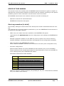
Operation Manual RHEONIK RHE 15 PROFIBUS DP SLAVE INTERFACE FOR MASS FLOWMETER RHEONIK the Coriolis Flowmeter experts REV. 1.3 March 2012 GE Measurement & Control reserves the right to make changes without notice at any time G E M ea su r em ent & Cont ro l RE V . 1 .3 M ar ch 2 0 1 2 TABLE OF CONTENTS Page SCOPE OF THIS MANUAL 3 Start-up procedure (in brief) 3 1. Introduction 4 2. GSD file 5 3. Add slave to PROFIBUS DP 7 4. Changing slave station address 5. 6. 4.1. Via PROFIBUS DP 17 4.2. Via RS232 Terminal Program 18 Parameterization 5.1. Gateway Parameters 19 5.2. Counter Parameters 20 5.3. Board Temperature Parameters 21 5.4. Analog Input Parameters 21 PROFIBUS DP Communication 6.1. Cyclic Data Transmission 22 7. PROFIBUS DP connection 24 8. Gateway and inputs connection 25 9. Troubleshooting 26 10. Technical Data 27 11. PROFIBUS DP Master Simulator 33 12. Motherboard overview 35 A P P E N D I C E S: Installation Plan RHE 15 to RHE 12 Installation Plan RHE 15 to RHE 14 Installation Plan RHE 15 to RHE 07, RHE 08 and RHE 11 PNO Registration . RHEONIK Coriolis Flowmeter Operation Manual RHE 15 Page 2 G E M ea su r em ent & Cont ro l RE V . 1 .3 M ar ch 2 0 1 2 SCOPE OF THIS MANUAL This manual covers the interface part of RHEONIK mass flowmeters for gases or liquids. It describes the communication between the device and the operator according to the specific (fieldbus) protocol. More information can be found in other documents. GE-RHEONIK instruments have modular instruction manuals consisting of: - Operation manuals for mass flowmeters - PROFIBUS DP Interface description Start-up procedure (in brief) All necessary settings for this module have already been made at GE Measurement & Control. The quickest way to get this module operational in your own PROFIBUS DP environment is to follow the next steps carefully. - Make sure your master has been installed in the PROFIBUS DP system - Load GSD the file RHEO0A56.GSD into the configuration tool (software at PROFIBUS DP Master) - Bitmaps (supplied in addition to the GSD file) can be copied in the correct directory (mostly automatic, sometimes manually; this depends on the configuration program) - Add your slave to the PROFIBUS DP system: Select "RHE15 RHEONIK" and add new instrument to the bus (with configuration tool) - Set slave configuration: Select module wanted out of the available list with modules (only one is selectable). These modules are the measurement data for mass flowmeters, which are available for cyclic reading/writing by a PROFIBUS DP master. Selectable measurement data variables: Shortcut: Description: PV SV TV QV BT AI1 AI2 AI3 TOT Primary Variable (mass flow rate) Secondary Variable (mass flow totalizer) Third Variable (mass flowmeter temperature) Variable (measurement frequency or density) RHE15 board temperature Analog input 1 (0 – 20 mA) Analog input 2 (0 – 20 mA) Analog input 3 (0 – 20 mA) Scalable pulse counter/totalizer Minimum selection (default selection) will probably be "PV, SV". These data are stacked into your master input memory. . RHEONIK Coriolis Flowmeter Operation Manual RHE 15 Page 3 G E M ea su r em ent & Cont ro l - RE V . 1 .3 M ar ch 2 0 1 2 Set parameter data of parameter values: These settings are copied to the instrument only at start-up. Examples of parameters are: Gateway protocol (depending upon firmware implementation), counter settings, units, analog input dampening. Setting parameter data is not necessary, but optional. - Set slave station address: Devices are delivered to customers with default address 126. This is the agreed station address for PROFIBUS DP systems for installing new instruments to a system. Normally, setting an address can be performed by your master configuration software. However, if you choose to set a station address off-line you can use a master simulator program (available from GE) to change the PROFIBUS DP station address and check all bus functions. Or you can use the RS232 connection and a Windows terminal program. See section "Changing slave station address" for more details. - Download all configuration settings into your master. - Test data exchange communication between your master and the instrument (s), f. e. using the Master simulator. 1 Introduction This manual explains how to install a RHEONIK mass-flowmeter to your PROFIBUS DP system. It only consists of such information, which is needed the most. More detailed information about PROFIBUS DP can be obtained on the website of the (international) PROFIBUS DP organisation: www.profibus.com or on the website of the (local) PROFIBUS DP organisation of your country (when available). This PROFIBUS DP interface offers a direct connection to PROFIBUS DP for RHEONIK mass flowmeters. Making use of the VPC3 chip from PROFICHIP, on the PROFIBUS DP the instrument will behave as a slave. This means all communication (instructions/readout) will be performed by a master on the same PROFIBUS DP segment. Mostly this will be any PLC or PC card controlling a process. There is no mutual communication between PROFIBUS DP slaves - only between master and slave. Each slave must have its own unique station address on the bus, otherwise no communication is possible. Setting slave station address can be performed by either: - Master configuration software - RS232/Terminal Program - RHEONIK master simulator software: PC software plus RS232/PROFIBUS DP connector The simulator tool can be used for a quick check of the RHE15 RHEONIK device communication on the PROFIBUS DP. If you don’t have such a master simulator you can order it from your local sales representative. PROFIBUS DP slaves using a VPC3 chip will automatically adapt the baud rates determined by the master on a bus segment. . RHEONIK Coriolis Flowmeter Operation Manual RHE 15 Page 4 G E M ea su r em ent & Cont ro l RE V . 1 .3 M ar ch 2 0 1 2 I m p o r t a n t: In the next paragraphs, some example displays will demonstrate how to use a master configuration tool for installing a RHEONIK meter as a PROFIBUS-DP slave. The tool used for these demonstration purposes is: COM PROFIBUS DP from Siemens (in this manual) Others like Step 7 from Siemens for PLC type S7-300 2DP (manual on special request, in preparation) are very similar. For various master configuration software tools the procedure will be almost the same, because PROFIBUS DP is a standardised field bus system. There can only be differences in details and program operation. 2 GSD file Each type PROFIBUS DP device has its own GSD file with instrument specifications to tell the master configuration software which facilities/features the instruments offer to the PROFIBUS DP system. For RHE15 RHEONIK the file is called: RHEO0A56.GSD. This file is available by CD-ROM or can be ordered by contacting GE The GSD file is a text file containing: Identification info: Model name: "RHE15 RHEONIK" Vendor name: "RHEONIK" – (future change to GE) Ident. number: 0x0A56 Bitmap device: "0A56_dev" Bitmap Diag: "0A56_dia" Bitmap SF: "0A56_spf" (Bitmap files are used in configuration software to indicate instrument status) Revision numbers Hardware characteristics: VPC3-ASIC specific properties Software characteristics: Supported features of PROFIBUS DP: Auto-baud rate detection Max. Bus data lengths: Size of used data buffers Parameter dialog-boxes: Parameter data for a-cyclic instrument variable settings Modules configurations: Possible Modules with cyclic input/output variables for the device . RHEONIK Coriolis Flowmeter Operation Manual RHE 15 Page 5 G E M ea su r em ent & Cont ro l RE V . 1 .3 M ar ch 2 0 1 2 Note: After starting-up your master configuration software, this GSD file should be loaded/imported/copied. This is necessary only once (until the next revision from the file is available). Some configuration tools offer viewing screens to monitor important GSD settings. The GSD file is a text file and can be opened with any text editor. For a detailed understanding of its contents, consult the PROFIBUS DP technical guideline "Specification for PROFIBUS DP Device Description and Device Integration", Volume 1: GSD 5.0, August 2003. A free GSD editor is/was also available at www.profibus.com : . RHEONIK Coriolis Flowmeter Operation Manual RHE 15 Page 6 G E M ea su r em ent & Cont ro l 3 RE V . 1 .3 M ar ch 2 0 1 2 Add slave to PROFIBUS DP A first example of this procedure can be found below: The GSD file supplied (RHEO0A56.GSD) must be copied to the GSD folder used by COM PROFIBUS DP or the equivalent PROFIBUS DP configuration tool supplied by the PLC vendor. The RHEONIK device can then be added to the PROFIBUS DP network by selecting OTHER and "RHE15 RHEONIK" from the list. The following sequence shows how to include the RHE15 device in a field bus network using COM PROFIBUS DP. 1. Launch the window shown below and click on "Others": 2. Choose the node address: . RHEONIK Coriolis Flowmeter Operation Manual RHE 15 Page 7 G E M ea su r em ent & Cont ro l RE V . 1 .3 M ar ch 2 0 1 2 3. Add the Box Icon to the network on the left and the Slave Parameters dialogue opens. Choose "RHE15 RHEONIK" from the list as shown here: 4. Click on "Configure" and choose the Slave Configuration from the list: 5. Click on "Parameterize" and change the start-up parameters or use the default values: . RHEONIK Coriolis Flowmeter Operation Manual RHE 15 Page 8 G E M ea su r em ent & Cont ro l RE V . 1 .3 M ar ch 2 0 1 2 6. For example, click on "counts" in the column Value and Select and choose the parameter Counter UNIT from the list: 7. Click OK and the RHE15 RHEONIK appears on the diagram like this: Now add any other nodes to the network that are required and close the window. Finally export the file in the required format, usually binary, for use by the PLC or other PROFIBUS DP Master. The master now searches for the RHE15 RHEONIK on the PROFIBUS DP network and when found connects to it and starts transferring the variable blocks. The red LED on the device slowly stops blinking and goes off when the data exchange is O.K. and the green LED lights up. . RHEONIK Coriolis Flowmeter Operation Manual RHE 15 Page 9 G E M ea su r em ent & Cont ro l RE V . 1 .3 M ar ch 2 0 1 2 A second example is using the Master Simulator Program: 1. Launch the window shown below and click on "File, Open GSD" and choose the file named RHEO0A56.GSD: 2. Open the "Communication Settings" window via "Communication, settings" and choose the COM port for the connecter Master Simulator PROFIBUS DP UART: . RHEONIK Coriolis Flowmeter Operation Manual RHE 15 Page 10 G E M ea su r em ent & Cont ro l RE V . 1 .3 M ar ch 2 0 1 2 3. In the Configuration Editor window choose the configuration from the module list and click on "Insert". The configuration selected appears in the Current Configuration list (only one choice). Click on "OK": 4. Click on Address, Search PROFIBUS DP Slave Address Window. The Search Slave address window opens as shown here: . RHEONIK Coriolis Flowmeter Operation Manual RHE 15 Page 11 G E M ea su r em ent & Cont ro l RE V . 1 .3 M ar ch 2 0 1 2 5. Click on "Address, Start search PROFIBUS DP slave address". The master simulator starts scanning all addresses from 1 to 126 for connected nodes. Once a connected node is detected the node appears with its address and ID number in the Search Address window: 6. For establishing a point-to-point connection to one of the nodes, enter the node address in the "current address" text field of the communicator window and click on "Communication, Start with GSD". Once connected, the "Communication Active Status" displays "connected" and the list fields "Input Data", "Output Data" and "Diagnosis" are cyclically updated with the node data as shown here: . RHEONIK Coriolis Flowmeter Operation Manual RHE 15 Page 12 G E M ea su r em ent & Cont ro l RE V . 1 .3 M ar ch 2 0 1 2 7. For change of any device parameter first close the communicator window, next from the File menu choose “Open GSD”. In the Open GSD dialog window select the RHE15 GSD file named “RHEO0A56” from the folder of the drive where it is located. In the configuration window double click on “Global” for access of the parameter setup. Note: It is important to remember that the parameter can be accessed only by double clicking the list item “Global” in the Current Configuration list. Any other more intuitive access function like a button doesn´t exists. . RHEONIK Coriolis Flowmeter Operation Manual RHE 15 Page 13 G E M ea su r em ent & Cont ro l RE V . 1 .3 M ar ch 2 0 1 2 . RHEONIK Coriolis Flowmeter Operation Manual RHE 15 Page 14 G E M ea su r em ent & Cont ro l RE V . 1 .3 M ar ch 2 0 1 2 In the Global window choose the parameter from the Parameter Name drop down list. For example “counter unit”. A detailed description of all parameter functions can be found in section 5 of this instruction manual. . RHEONIK Coriolis Flowmeter Operation Manual RHE 15 Page 15 G E M ea su r em ent & Cont ro l RE V . 1 .3 M ar ch 2 0 1 2 Next select all other possible parameter options like Text, Value etc. . RHEONIK Coriolis Flowmeter Operation Manual RHE 15 Page 16 G E M ea su r em ent & Cont ro l 4 RE V . 1 .3 M ar ch 2 0 1 2 Changing slave station address When you have installed your RHE15 RHEONIK PROFIBUS DP slave and made the correct settings for slave configuration and parameter data, you can give your device the slave address you want. Delivered devices have the default slave address 126. This address has been agreed by the PROFIBUS DP organisation to be free for installing new devices to the bus. In principle, any address in the range 1 to 125 is possible. The master on the PROFIBUS DP recognises that an address has not been specifically issued to this device from the factory setting 126. We recommend setting an address > 30 for the device as addresses below 30 are normally issued to masters. Each address on the PROFIBUS DP may only be issued once. The address can only be changed if there is no cyclical communication. Changing the station address can be performed in two different ways: 4.1 Via PROFIBUS DP: This is the normal way to change addresses. Your PROFIBUS DP configuration tool must allow online connections. Point to actual slave in your master configuration tool and select [online] [Set slave address]. Enter correct old address and new address and press [Set address]. Example: Some configuration tools allow checking the re-address action using the option "Live list". This gives an overview of all masters and slaves connected to a PROFIBUS DP segment similar to this: . RHEONIK Coriolis Flowmeter Operation Manual RHE 15 Page 17 G E M ea su r em ent & Cont ro l RE V . 1 .3 M ar ch 2 0 1 2 Note: The address setting is not lost when the slave is switched off. The information is buffered in a non-volatile memory inside the device. I m p o r t a n t: If you choose to change the slave addresses online for more than one newly delivered RHE15 RHEONIK slave, on the same segment, for the first time, (all have default address 126) make sure that you switch on each device one by one and modify its address first before doing the same procedure for the next one. 4.2 Via RS232: Terminal Program "Off-line" via RS232-service communication port by means of a terminal program, f. e. HyperTerminal, which can be found in the communications tool folder of your Windows operating system. HyperTerminal is a terminal program which allows sending and receiving ASCI characters to the connected device. 1. Connect your RHE15 RHEONIK PROFIBUS DP slave device to a free COM port of your PC/laptop using the supplied RS232 cable with 3 free wires on one side, for connection to the RHE15 terminal block and a female sub-D 9 connector on the other side. (see wiring diagram). 2. Open HyperTerminal and enter a new name for your connection (f. e. Address Setup). Choose the appropriate COM port for the connected RS232 cable from the connection drop-down menu. Chose the "COM Properties" as following: Bits per second: 1200 Data Bits: 8 Parity: odd Stop bits: 1 Flow control: none 3. Click "OK". The terminal window opens with a flashing cursor. The message "Connected" appears in the status bar at the bottom of the terminal window, along with the elapsed time display. 4. From the menu bar, select "Files, Properties" then the settings tab on the "Properties" dialog. Click on the ASCII setup button and check the Echo typed characters locally check box in the following dialog box is unchecked. Click in OK to exit the dialog, then "OK" to exit the "Properties" dialog. 5. Connect the RHE15 GE-RHEONIK RS232 cable to your laptop/PC and switch on the device. After some time the following configuration menu appears in the terminal program like this: Old address: 126 Enter New (0-126): _ In this example the old (existing) PROFIBUS DP address is 126. . RHEONIK Coriolis Flowmeter Operation Manual RHE 15 Page 18 G E M ea su r em ent & Cont ro l RE V . 1 .3 M ar ch 2 0 1 2 6. On being prompted, type the new PROFIBUS DP node address (possible range 0 – 126). Type in exactly the three decimals of the address, without typing anything else on your keyboard. The new address must be input in the format with leading 0´s. For example 005 for Address 5. Old address: 126 Enter New (0-126): 005 7. Once the three digits have been correctly entered, a new line is displayed like this: Save New 5 (y/n)? _ In this example, the new PROFIBUS DP address should be set to 5. 8. On being prompted, type y for "yes" or n for "no", depending on whether you want to save the new setting or not. After a successful saving, the terminal window displays: Saved.. Other ways, with no saving: Aborted.. Note: If you wish to repeat the address setting, you must restart the device, because the unit has already left the address setting mode. Afterwards, follow the points of this instruction again. 9. Close the terminal session. The RHE15 RHEONIK device is now ready to communicate on the PROFIBUS DP. Connect the RS232 communication port to the field device and restart the RHE15 RHEONIK (switch power supply off and on). 5 Parameterization Any bus configuration tool such as COM PROFIBUS DP, Step7, etc. can be used for the parameter setup. Some parameters are standardised for all PROFIBUS DP slave devices. Extra parameters for specific functions are device-dependent. The configuration tool obtains all necessary information about built-in device-specific parameters reading the device GSD file. The following is a description about the functionality behind the specific RHE15 RHEONIK parameters. Parameters are transferred on the bus during the start up of the communication between PROFIBUS DP master and slave using the parameterization protocol. The slave checks the parameters for correctness (f. e. correct number of parameters etc.) and enters the data exchange mode only after successful parameterization (and configuration). 5.1 Gateway Parameters The device operates by default as a protocol gateway between HART and PROFIBUS DP. HART via RS232. The device acts as a HART master and PROFIBUS DP slave. The HART connection is a point-to-point mode only. The connection does not support burst mode. . RHEONIK Coriolis Flowmeter Operation Manual RHE 15 Page 19 G E M ea su r em ent & Cont ro l RE V . 1 .3 M ar ch 2 0 1 2 The implemented HART Revision 5. commands are: HART #0 #3 #42 #52 Commands Read unique identifier Read current and four dynamic variables Perform master reset Set transmitter variable zero Parameter "RS232/Gateway": This parameter can be used to switch off the RS232/Gateway (disable). The Gateway is enabled by default and continuously polls the connection for a HART slave device, using HART command #0. Once connected, the normal HART communication starts reading the field device dynamic measurement variables. Parameter "Gateway PROTOCOL": The HART protocol is chosen by default. Other protocols from the list are for future expansion. 5.2 Counter Parameters The pulse counter can operate in two modes, in a pure counter mode or in a scalable pulse counter mode. The maximum count is 2147483647 (7FFFFFFF hex). Rolling over the maximum count resets the counter to zero. The maximum pulse frequency is 10 kHz. The counter value is not buffered when the slave device is switched off. Four parameters are provided to set up the counter operation mode: Parameter "Counter RESET by bus enable": This parameter has two values: enable (default) or disable. Disabling the RESET by bus function means that the counter cannot be reset by the master output. The master output bit for counter reset is ignored (safety feature). Parameter "Counter HOLD by bus enable": This parameter has two values: enable (default) or disable. Disabling the HOLD by bus function results in the master hold output bit being ignored. Parameter "Counter UNIT": The counter unit parameter has several choices of mass and volumetric units for the counter and another unit "counts" (default). With unit "counts", the counter works as a pure pulse counter, with all other units the counter runs in a scalable counter mode in physical units. Parameter "PULSES per UNIT (1 – 65535)": The selectable range is 1… 65535. In the unit="counts" mode, this parameter is 1 by default. For all other mass and volumetric units the parameter must be set to the number of pulses (K-Factor) of the flowmeter. For example: The mass flowmeter is calibrated for 756 pulses per kilogram. In that case, the parameter unit must be set to "kg" and the parameter "PULSES per UNIT" to 756. With this set of parameters, the counter counts the pulses in physical unit kg. . RHEONIK Coriolis Flowmeter Operation Manual RHE 15 Page 20 G E M ea su r em ent & Cont ro l RE V . 1 .3 M ar ch 2 0 1 2 Note: The maximum count is 2147483647 pulses. The scaled counter rolls over at 2147483647 / Pulses per Unit. As an example: With 756 pulses per kilogram the counter rolls over at 2840586 kg. 5.3 Board Temperature Parameters The device has a built-in temperature sensor to measure the board temperature. This information can be used for external diagnosis of the ambient temperature at the installation condition (cabinet). Measurement range of the sensor is 0°C .. 100°C. Parameter "Board temperature UNIT": The physical unit of the temperature measurement is selectable (°C, °F, K) with this parameter. Note: The maximum ambient temperature of the device is 60°C. Higher temperatures might result in permanent damage of electronic components. 5.4 Analog Input Parameters Three analog measurement channels with a resolution of 10 bits are built in for measurement of current signals in the range 0 – 20 mA. The channels cannot source the current to connected sensors etc., so the devices must have an active current loop. Parameter "Analog filter SIZE": This parameter influences the dynamic behaviour of the current measurement. The last 8 sampled values are continuously averaged by default. Higher settings are for better filtering of noisy measurements. 6 PROFIBUS DP Communication RHE15 RHEONIK has a PROFIBUS DP V0 connection. The baud rate detection is automatic; all possible baud rates are listed in the technical data table of this instruction manual. The min TSDR (smallest station delay time, at start up is 11 bit times and can subsequently be changed using the Set_Prm service. Note: min TSDR (= minimum station delay time of responder): In this parameter the master on the PROFIBUS DP sets the minimum waiting time, which the RHE15 RHEONIK slave has to observe, before it answers a master telegram (unit: bit time = time for 1 bit at selected baud rate). The bus address has the value 126 as delivered and can either be changed with the Set_Slave_Add DP service or via RS232. Communication uses the EN 50 170 standard (PROFIBUS DP V0). The data transmission and data formats are described in the following sections. . RHEONIK Coriolis Flowmeter Operation Manual RHE 15 Page 21 G E M ea su r em ent & Cont ro l RE V . 1 .3 M ar ch 2 0 1 2 The following DP services are supported as slave for a DP master class 1: Standard Shortcut Meaning Service Access Point Wr_Rd_Data Set_Slave_Addr Rd_Inp Rd_Outp Global_Control*) Get_Cfg Slave_Diag Set_Prm Chk_Cfg Data exchange Changing the station address Reading the inputs Reading the outputs Control commands for the DP slave Reading configuration data Reading diagnostics information Sending parameter setting data Checking configuration data Default SAP SAP55 SAP56 SAP57 SAP58 SAP59 SAP60 SAP61 SAP62 *) Accepted, but not supported 6.1 Cyclic Data Transmission Cyclic data transmission is used to transmit input and output data between master class 1 (control system or PLC) and the slave (RHE15 RHEONIK). Inputs (to Master) and Outputs (from Master): Up to five different measured values (= one module) can be transmitted cyclically as input data in a telegram with the Data_Exchange service. The five different values are selectable in different combinations out of 9 possible measurement values, depending on the user application (1 configuration module from 12 selectable modules). The following measured values are available as inputs: Shortcut: PV SV TV QV BT AI1 AI2 AI3 TOT Description: Primary variable (mass flow rate) Secondary variable (mass flow totaliser) Third variable (mass flowmeter temperature) Variable (measurement frequency or density) RHE15 board temperature Analog input 1 (0 – 20 mA) Analog input 2 (0 – 20 mA) Analog input 3 (0 – 20 mA) Scalable pulse counter/totaliser Output data are sent to the device together with the cyclic request telegram. The number and type of the data actually transmitted can be defined with the configuration data. Input data (from slave to master) are user data (measured values), which are transmitted from the device to the master in the following format: Every measured value consists of 5 bytes, which are composed of a floating point value corresponding with IEEE -- 754 (4 bytes) and the appropriate measurement unit (1 byte). First the measured value and then the corresponding unit is transmitted in the PROFIBUS DP telegram. The structure of a 4 byte floating point value can be found in the technical data table at the end of this instruction manual. . RHEONIK Coriolis Flowmeter Operation Manual RHE 15 Page 22 G E M ea su r em ent & Cont ro l RE V . 1 .3 M ar ch 2 0 1 2 The unit byte can have the following values: Value: 60 61 62 125 63 64 Unit: g kg t oz lb tn Value: 41 250 43 113 40 124 Unit: l ml m³ in³ ga ba Value: 74 81 75 78 96 93 Unit: kg/min lb/min kg/h t/h kg/l lb/ga Value: 32 33 35 240 39 38 Unit: °C °F K counts mA Hz The RHE15 accepts three output bytes (from the master) and another four output bytes representing a floating point value with one byte unit. The outputs configuration is the same for any selected configuration of the inputs: GC: Gateway control byte TC: Pulse counter control byte AC: Analog input control byte DO: Data output variable (float) plus unit code (5 Bytes) Each control byte has several bits, which are used for control. The structure of the output bytes and the bit numbers, which are currently defined, can be found in the data table at the end of this instruction manual. Bits without name are reserved for future expansion and should not be used (masked out) by the master. The following provides a short description of the bit functions: Bit GC.Debug Mode On/OFF (GC.8): Setting this bit activates the device debug mode. This function is for factory purposes only and is not published to the end user. Bit GC.Restart Field Device (GC.2): Whenever the RHE15 finds this bit set, it restarts (warm start) the connected field device (f. e. mass flowmeter). This function is only available with data communication via HART/RS232 connection. The restart function in only triggered once by setting this bit. The bit must be cleared first and set again for a new activation. Note: Restarting the field device prevents measurement data transmission for about 20 seconds. This is the time taken for rebooting the device. Bit GC.Reset Quantity (GC.1): A "1" in this bit field triggers a reset of the quantity (flow totalizer) of the field device (mass flowmeter etc.). In the same way as for the restart bit, this function is only triggered by the "0" to "1" transition of the bit. Bit TC.HOLD ON/OFF (TC.2): Setting this bit will hold on the counter counting the pulses at its input. The HOLD mode is active as long as the bit is set. Bit TC.RESET (TC.1): . RHEONIK Coriolis Flowmeter Operation Manual RHE 15 Page 23 G E M ea su r em ent & Cont ro l RE V . 1 .3 M ar ch 2 0 1 2 The function of this bit is the same as for the Reset Quantity bit; except in this case the pulse counter is reset. Bit AC.HOLD ON/OFF (AC.2): All three analog inputs retain the last measured value whenever this bit is set (freeze analog inputs). Bit AC.Filter ON/OFF (AC.3): This bit deactivates the analog input filtering (fastest response time). Whenever this bit is "0" the parameterised filter value is active again. Data output variable (DO): This output value from master to slave (floating point number with unit byte) is currently not used in the firmware (reserved in the output map for future expansion). 7 PROFIBUS DP connection The PROFIBUS DP connection can be done either by a 9-pin connector or by 6 screw terminals beside the connector. The female PROFIBUS DP (x) (sub miniature 9-pin) D-connector and the terminals have the following pin/terminal configuration: Pin number: 1 2 3 4 5 6 7 8 9 Terminal number: 6 3 4 1 5 2 - Signal: Meaning: Shield Not connected RxD/TxD-P CNTR-P (RTS) DGND VP (+5V) Not connected RxD/TxD-N Not connected Cable shield Data + Request to send Reference potential (ground) Power supply +5V / 50 mA Data - Note: At the connections of the first and the last device, the ends of the PROFIBUS DP bus segment must be terminated by a resistor network. . RHEONIK Coriolis Flowmeter Operation Manual RHE 15 Page 24 G E M ea su r em ent & Cont ro l RE V . 1 .3 M ar ch 2 0 1 2 The RHE15 RHEONIK device has resistor networks already built in, which can be activated via two DIP switches. Some PROFIBUS DP connectors are also available with built-in switchable resistor networks. Care must be taken not to activate both termination resistors, in the device and connector; otherwise the communication will not work. The shield of the cable must be connected to the earth protection, but not to DGND. The dip switches on the RHE14 board are relatively fragile. Avoid touching them with large screwdrivers, and avoid applying heavy force during activation. 8 Gateway and inputs connection The device has the following terminals as gateway connection and measurement inputs: Terminal number: Signal: Meaning: 24 23 22 21 20 19 +24 V GND ANALOG0 ANALOG1 ANALOG2 +5V 18 17 16 15 14 13 GND PULSE GND TxD RxD GND Power supply input, max. 50 mA sinking Reference potential Analog input #0 (0-20 mA, sinking) Analog input #1 (0-20 mA, sinking) Analog input #2 (0-20 mA, sinking) Power supply output, max. 50 mA sourcing Reference potential Pulse counter input (+5V, sourcing) Reference potential Tx-RS232 (gateway interface) Rx-RS232 (gateway interface) Reference potential Note: Terminal numbers 23, 18, 16, 13 are internally connected to GND. Terminal 19 (+5 V) can be only used as a low power supply with maximum 100 mA output current. This output is not fused! Terminal 17 provides an internal 1 kOhm pull-up resistor for open collector pulse outputs. Active pulse outputs with TTL level can be connected as well. All GND terminals are galvanically isolated to the bus. Do not connect any of them with terminal 1 (DGND). The RS232 cable length in between field device and RHE15 RHEONIK is limited to 10 meters. A shielded data transmission cable must be used. For longer distances RS232 repeaters or converters RS232-RS422 must be used (consult factory). . RHEONIK Coriolis Flowmeter Operation Manual RHE 15 Page 25 G E M ea su r em ent & Cont ro l 9 RE V . 1 .3 M ar ch 2 0 1 2 Troubleshooting PROFIBUS DP problems Check power supply and wiring. Check bus termination at the beginning and end of a bus segment. Termination must be enabled either in the RHE15 RHEONIK device (DIP switch in ON position) or by means of any external special resistor network, f. e. resistor network and switch inside the bus connector (see www.profibus.com for more details). Parallel enabled termination resistors in the device and PROFIBUS DP connector must be avoided! Check node address (slave). Try to restart the node and/or your master. Make sure that all settings for the node (slave) are downloaded to your master (otherwise it will not work). Contact PROFIBUS DP sales representative or service department. Other problems Contact GE- local sales/ service representative . RHEONIK Coriolis Flowmeter Operation Manual RHE 15 Page 26 G E M ea su r em ent & Cont ro l 10 RE V . 1 .3 M ar ch 2 0 1 2 Technical Data Advantages of RS485 (DP) versus MBP (PA) Transmission Media RS485 No extra bus power supply necessary /not bus-powered Higher operation reliability: DP device still working with bus power failure (PA-devices will have black out!) Lower interface costs and complexity, higher robustness High bus transmission speed (up to 12000Kbit/s), with PA device only 315Kbit/s Selectable transmission speed (Baud rate), can be adapted to the bus situation, depending on the extension of a bus segment Larger distances in between single bus devices possible Physically more bus participants possible (very limited with PA devices, because of explosion protection) Higher flexibility, no additional segment coupler for connection to the DP segment necessary Lower system costs (no extra costs for bus power supply, segment coupler etc.) Recommended cable type : Cable code Interconnection technology 2-wire PROFIBUS DP cable, SUB-D-9 connector or terminals Supplier Colour of sheath Standard Classification Loop resistance max. Impedance Mutual capacitance max. Coupling resistance approx. Screen resistance max. Capacitance unbalance to earth max. Attenuation at 0.25/0.625/2.25/3.125/16 MHz nominal Test voltage Operating voltage max. Outer diameter Weight approx. Pulling tension max. Bending radius Flame retardancy Oil resistance Operating temperature UV resistance Glands Cable laying FB-02YS(ST+C)Y-fl STD 1x2xAWG22/1 Kerpen (74220002) violet EN50170-2 Type A 110 Ohm/km 150 Ohm+-10% > 3MHz 30 nF/km 3.5 Ohm/km at 10 MHz 9 Ohm/km 1500 pF/km 6/9/12/18/40 dB/km 1000 V 300 V 7.9+- 0.3 mm 70 kg/km 80 N 60 mm Acc. To IEC 60332-3 Partly resistant, ICEA S 61-402 -40°C up to +70°C UL1581 section 1200 PG9, PG11, M16 For fixed installation, indoor and outdoor, on racks, in conduits . RHEONIK Coriolis Flowmeter Operation Manual RHE 15 Page 27 G E M ea su r em ent & Cont ro l RE V . 1 .3 M ar ch 2 0 1 2 Maximum segment cable length: Data transfer rate/Kbit/s Max segment length/ m 9.6 19.2 45.45 93.75 187.5 500 1500 3000 6000 12000 1200 1200 1200 1200 1200 400 200 100 100 100 Note: For RS485-is (intrinsically safe) the above-mentioned length can be shorter for safety reasons. The relevant national standards for IS or IEC60079 must be observed. Recommended connector type: Interconnection technology 2-wire PROFIBUS DP cable, SUB-D-9 connector or terminals Bus interface connector Supplier Classification Cable termination outlets Cable diameter Cross section of individual conductor Termination type Data transmission rate max. Temperature range Permissible humidity max. Protection class Housing material D-SUB screw UL approval Pin configuration Cable termination resistors Additional bus extension connector Colour D-SUB, 9 pin, male Erni, ERbic (144475) Class 2 2x horizontal, 1 cable outlet sealable 4.5 mm up to 8 mm Max. 1.5 mm² Screw terminal 12 Mbit/s -20 up to +70°C 75% at 25°C, non condensing IP40 Thermoplast ULV94V-1 UNC 4/40, knurled with cross-head UL EB4703 TerDSignal minal SUB Pin B(1) 3 RX/Tx-P A(2) 8 Rx/Tx-N B(3) 3 Rx/Tx-P A(4) 8 Rx/Tx-N 5 GND 6 VP(+5V ) Internal, via external switch D-SUB, 9 pin, female Slat grey Note: For RS485-is (intrinsically safe) the ERbic connector type PROFIBUS DP Ex-i (134727), colour blue with horizontal cable outlets is available. . RHEONIK Coriolis Flowmeter Operation Manual RHE 15 Page 28 G E M ea su r em ent & Cont ro l Address number implementation (software or hardware) Indicators or LED's Via software by Set_Slave_Address telegram (SAP55) DP ERROR (red bus failure LED) DX MODE (green data exchange LED) Baud rate range and detection Automatic detection Integrated terminating resistors On-board, selectable via 2 DIP switches or external inside connector Grounding and shielding Via connector casing or screw terminal PCB size and casing PCB: 63x81 mm Casing: acc. to DIN43880 Isolation and explosion class (IP and Ex) RE V . 1 .3 M ar ch 2 0 1 2 Selectable address range: 0 – 126 Addresses 0 and 126 are reserved addresses for test and commissioning and should not be used in normal operation! DP ERRORLED on flashing slowly DX MODELED off off on off PROFIBUS DP state: Power_on Wait_prm Wait_cfg Data_Exchange flashing off (Power_on) quickly Supported data transfer rates Kbit/s 9.6 19.2 93.75 187.5 500 1500 3000 6000 12000 Device state: Initialisation Ready, waiting for start-up Communication active Fatal error acc. to EN500170 500 VAC isolation to bus RS455-Exi according to PNO user and installation guidelines in preparation IP20 Recommended operating temperature range: -20 .. +40 °C Non Ex-i Power supply and current consumption +24 VDC. Max. 100 mA Possible operating Range: 8 – 24 VDC . RHEONIK Coriolis Flowmeter Operation Manual RHE 15 Page 29 G E M ea su r em ent & Cont ro l RE V . 1 .3 M ar ch 2 0 1 2 Structures: Inputs (to Master) 5x5 Byte consistent 3 single Bytes Outputs plus (from Master) 5 Byte consistent Slave Type PROFIBUS DP I/O map, modules and profile support 5 byte consistent Bits Octet #1 4 byte float Number in IEEE 754 floating point format 8 SN 7 6 27 26 2-1 2-2 1 byte Unit code byte 5 4 3 Exponent (E) 25 24 23 Fraction (F) 2-3 2-4 2-5 Fraction (F) Octet #2 (E) 20 Octet #3 2-8 2-9 2-10 Octet #4 2-16 2-17 2-18 2-11 2-12 Fraction (F) 2-19 2-20 2 1 22 21 2-6 2-7 2-13 2-14 2-15 2-21 2-22 2-23 Modular Slave SN: sign (0=positive, 1 = negative) Number of Modules Number of module configurations Profile support 1 Float calculation (binary to decimal): Number 12 (decimal) = (-1)SN * 2 (Exponent - 127) * (1 + Fraction) Example: 40 F0 00 00 (hex) = = 0100 0000 1111 0000 0000 0000 0000 0000 DP V0 Number Number (decimal) (decimal) (binary) = (-1)0 * 2 (129 - 127) * (1 + 2-1 + 2-2 + 2-3) = 1 * 4 * (1 + 0.5 + 0.25 + 0.125) = 7.5 Note: 10000001 (binary) = 129 (decimal) Unit Codes: Value: 60 61 62 125 63 64 Diagnostics Parameters Unit: g kg t oz lb tn Value: 41 250 43 113 40 124 Unit: l ml m³ in³ ga ba Value: 74 81 75 78 96 93 Unit: kg/min lb/min kg/h t/h kg/l lb/ga Value 32 33 35 240 39 38 Unit: °C °F K counts mA Hz 6 bytes standard diagnostics (acc. to EN500170) 7 bytes standard parameters (acc. to EN500170) Sync_Req and Freeze_Req is not supported Plus 8 extra user parameter bytes Parameter RS232/Gateway Counter RESET by bus Counter HOLD by bus Counter UNIT PULSES/UNIT Gateway PROTOCOL Board temperature UNIT Analog filter SIZE Selectable values enable/disable Default value enable enable/disable enable enable/disable enable counts/kg/g/t/oz/lb/tn(short)/ ml/Liter/m3/in3/gal/ba 1 - 65535 HART/RHEONIK_1 .. RHEONIK_10/OTHER_1 .. OTHER_10 counts 1 HART Kelvin/Celsius/Fahrenheit Celsius 8/16/32/64 8 . RHEONIK Coriolis Flowmeter Operation Manual RHE 15 Page 30 G E M ea su r em ent & Cont ro l RE V . 1 .3 M ar ch 2 0 1 2 Possible configurations: Configuration # 1 2 3 4 5 6 7 8 9 10 11 12 Configuration 1 configuration from 12 possible configurations selectable Shortcut PV SV TV QV TOT AI1 AI2 AI3 BT GC TC AC DO Inputs (to master) PV PV, SV PV, SV, TV, QV, BT PV, SV, QV, TV, TOT PV, TOT, AI1, AI2, BT PV, AI1, AI2, AI3, BT TOT TOT, AI1 TOT, AI1, AI1, AI3, BT AI1 AI1, AI2 AI1, AI2, AI3, BT Outputs (from master) GC, TC, AC, DO GC, TC, AC, DO GC, TC, AC, DO GC, TC, AC, DO GC, TC, AC, DO GC, TC, AC, DO GC, TC, AC, DO GC, TC, AC, DO GC, TC, AC, DO GC, TC, AC, DO GC, TC, AC, DO GC, TC, AC, DO Description Primary variable plus unit code Secondary variable plus unit code 3’rd variable plus unit code 4’th variable plus unit code Pulse counter (totaliser) plus unit code Analog input 1 plus unit code Analog input 2 plus unit code Analog input 3 plus unit code Board temperature plus unit code Gateway control byte Pulse counter control byte Analog input control byte Data output variable (float) plus unit code Note: all unit code bytes are according to the HART ™ universal unit code table Structures of control bytes: Bits 8 DEBUG MODE ON/OFF 7 6 5 4 3 - - - - - TC byte - - - - - - AC byte - - - - - FILTER ON/OFF GC byte Acyclic communication (DPV1) Not implemented Process reaction time (between PROFIBUS DP and I/O About 300 ms 2 RESTART FIELDDEVICE HOLD ON/OFF HOLD ON/ OFF 1 RESET QUANTITY RESET - . RHEONIK Coriolis Flowmeter Operation Manual RHE 15 Page 31 G E M ea su r em ent & Cont ro l GSD file architecture See file RHEO0A56.GSD RE V . 1 .3 M ar ch 2 0 1 2 Revision 1, Date: 13 Sept. 2006 Self-diagnostics and sophisticated watchdog timers simplify maintenance and troubleshooting. The watchdog timer invokes a failsafe condition if host communication is lost. For further security, a second watchdog monitors the microcontroller for failed operations or a "lockup" condition and automatically resets the unit. Failsafe states Supported protocols: -HART (via RS232) (others in preparation or on request) - The Gateway is acting as HART master Point-to-point Mode (HART slave device polling address must be 0 ) Establish communication with HART command 0 Continuous auto polling for device data with HART command 3 Multidrop mode not supported Primary master operation Transmitter analog measurement channels 3 analog input channels - analog input range 0-20 mA measurement resistance 200 Ohm 10 bit resolution shortest measurement time constant 10 ms Transmitter digital measurement channel 1 pulse/frequency input channel - operating range 0 – 10 kHz - measurement units: counts, kg, g, t, oz, lb, tn, ml, l, m³, l, ml, in³, gal, ba (selectable as PROFIBUS DP parameter) - pulses per mass unit (selectable as PROFIBUS DP parameter) Communication Gateway Transmitter self diagnostics - Communication check incl. CRC Input channel overrange Watchdog timer Memory check Maximum electronics temperature measurement Product name RHE15 RHEONIK Only one 0A56 User manual Instruction Manual "PROFIBUS DP interface for mass flowmeter" Spare parts M704 board/ casing Ident number sequence Support and service Costs . RHEONIK Coriolis Flowmeter Operation Manual RHE 15 Page 32 G E M ea su r em ent & Cont ro l 11 RE V . 1 .3 M ar ch 2 0 1 2 PROFIBUS DP Master Simulator Monitoring Software for PROFIBUS DP slaves PROFIBUS DP UART The PROFIBUS DP Master Simulator is easy-to-use software for data exchange with PROFIBUS DP slaves of many suppliers via PROFIBUS DP. The PROFIBUS DP Master Simulator can exchange data with many PROFIBUS DP slaves even without GSD file or type-file. The PROFIBUS DP slaves can be put into operation with the default I/O window. Input data can be read and output data can be written. Furthermore, the PROFIBUS DP Master Simulator also processes GSD files. User parameters can be edited and the configuration can be modified and stored. The PROFIBUS DP station address can be changed as well with the PROFIBUS DP Master Simulator; this is useful for PROFIBUS DP I/O modules in protection class IP67 without addressing switches. The PROFIBUS DP Master Simulator offers the possibility to scan a PROFIBUS DP network for connected slaves and display them in a graphical way. In this case, the PROFIBUS DP UART has to be connected directly to a PROFIBUS DP slave. The I/O data and the PROFIBUS DP user diagnosis can be displayed in binary form, hexadecimal form and also as ASCII code. The PROFIBUS DP output data can be transmitted consistently to the PROFIBUS DP slave. In type mode it is possible to set an output as long as the mouse button is pressed. The PROFIBUS DP Master Simulator consists of the software and the PROFIBUS DP UART, which is the ideal interface converter between the RS 232 interface of a PC and the PROFIBUS DP slave. The UART does not need any additional external power supply. Therefore it is also suitable for mobile use with a laptop or a notebook. The PROFIBUS DP UART is simply inserted between the PROFIBUS DP slave and RS 232 connector cable. However, the PROFIBUS DP UART is a monitoring and commissioning tool for PROFIBUS DP slaves, it is not designed to control automation processes. . RHEONIK Coriolis Flowmeter Operation Manual RHE 15 Page 33 G E M ea su r em ent & Cont ro l RE V . 1 .3 M ar ch 2 0 1 2 Technical data of PROFIBUS DP UART Type PROFIBUS DP UART Dimensions (L, W, H) 63 mm, 34 mm, 17 mm Interfaces Standard PC RS 232 interface with 9-pin D-sub-plug (female) RS 485-interface with 9-pin D-subplug (male) Requirements: IBM compatible PC 80386 or higher Operating system: Windows 98, Windows Me, Windows 2000, Windows XP or Windows NT Specification: Power supply Powered from the RS 485 interface of the PROFIBUS DP slave (5 V) Operating current < 60 mA Cable length RS 232 and RS 485: max. 2 m Transfer rate 19200 Baud Operating temperature Storage temperature Software: PROFIBUS DP Master Simulator PROFIBUS DP UART D-sub-data cable 0°C ... +55°C -25°C ... +70°C . RHEONIK Coriolis Flowmeter Operation Manual RHE 15 Page 34 G E M ea su r em ent & Cont ro l 12 RE V . 1 .3 M ar ch 2 0 1 2 Motherboard overview . RHEONIK Coriolis Flowmeter Operation Manual RHE 15 Page 35 G E M ea su r em ent & Cont ro l A P P E N D I C E S: Installation Plan RHE 15 to RHE 12 Installation Plan RHE 15 to RHE 14 Installation Plan RHE 15 to RHE 07, RHE 08 and RHE 11 PNO Registration RE V . 1 .3 M ar ch 2 0 1 2 optional wiring ! RHE 12 terminalbox (I/O,power supply) increased safety "e". R RHE 12 RHE 15 + Power Supply: 24 VDC/ 2,5 Watt (SELV) - 9 10 A 330R D 21 1 2 3 4 5 12 D 20 A 220R 200R 6 7 8 9 200R 13 19 +5V 330R 8 11 + - 14 18 15 17 16 16 TXIO 17 15 TXD RXIO 18 14 RXD GND Do NOT connect Bus cable screen to DGND ! DGND SHIELD/ CASING GND DGND COUNTER GND 300R RS232 7 Connect either SUB-D OR Terminals 1-6 VP R1K 6 D A 200R non intrinsically safe 5 CASING GND SUB-D (front view) female 9 contacts 22 + 4 23 - 3 intrinsically safe 2 24 RS485 Um = 28 VDC 1 6 SHIELD 5 VP 4 RTS 3 RxD/ TxD-P 2 RxD/ TxD-N 1 DGND +5V VCCOUT 19 GNDOUT 20 13 GND + - DGND PE CASING GND Terminal 22: AI1 Analog input 1 (0 – 20 mA) Terminal 23: AI2 Analog input 2 (0 – 20 mA) Terminal 24: AI3 Analog input 3 (0 – 20 mA) Terminal 17: TOT Scalable pulse counter/totaliser created : 23.10.2006 Date Drawn H.G.Rudolph M. Küppers Appr. Wiring diagram RHE 15 with RHE 12 Project Customer Draw. - Rev. Sheet E15_12W-E_v1_1 1/1 optional wiring ! R Um = 28 VDC RHE 14 RHE 15 24 + 24 2 23 - 23 3 22 AI1 22 4 21 AI2 21 1 RS485 RHE 15 Power Supply: 24 VDC/ 2,5 Watt (SELV) - SUB-D (front view) female 9 contacts D A Connect either SUB-D OR Terminals 1-6 VP + 200R 1 2 3 4 5 330R D A 5 20 AI3 20 6 19 +5V 19 D A 220R 200R 6 7 8 9 CASING GND 7 18 GND 18 8 17 TOT 17 9 16 GND 16 SHIELD/ CASING GND DGND TXD 15 TXD 15 11 RXD 14 RXD 14 13 GND 13 12 GND 6 SHIELD 5 VP 4 RTS +5V 3 RxD/ TxD-P + - 2 RxD/ TxD-N 1 DGND COUNTER 300R RS232 10 Do NOT connect Bus cable screen to DGND ! DGND R1K + - 330R 200R Filter DGND CASING GND Terminal 22: AI1 Analog input 1 (0 – 20 mA) Terminal 21: AI2 Analog input 2 (0 – 20 mA) Terminal 20: AI3 Analog input 3 (0 – 20 mA) Terminal 17: TOT scalable pulse counter/totaliser created : 07.11.2011 Date Drawn H.G.Rudolph U. Hettrich Appr. Wiring diagram RHE 15 with RHE 14 Project Customer Draw. - Rev. Sheet E15_14W-E_v1_2 1/1 R Um = 28 VDC RHE 08 19 20 RHE 07 22 + 24 - 23 AI1 22 RS485 RHE 11 RHE 15 Power Supply: 24 VDC/ 2,5 Watt (SELV) D A 0(4) - 20mA 13 * 22 25 CASING GND SUB-D (front view) female 9 contacts Connect either SUB-D OR Terminals 1-6 VP 200R AI2 D 21 A 330R Remote unit 1 2 3 4 5 AI3 D 20 A 220R 200R 6 7 8 9 200R + - 16 19 21 GND 18 17 15 17 TOT 17 12 21 23 GND 16 TXD 15 RXD 14 GND 13 330R 19 SHIELD/ CASING GND DGND 18 23 24 Do NOT connect Bus cable screen to DGND ! DGND R1K +5V COUNTER RS232 300R +5V + - 6 SHIELD 5 VP 4 RTS 3 RxD/ TxD-P 2 RxD/ TxD-N 1 DGND DGND CASING GND * second current output only with RHE 11 standard version (IA) not available with RHE 11 version (ID) created : 14.04.2008 Date Drawn H.G.Rudolph M. Küppers Appr. Terminal 22: AI1 Analog input 1 (0 – 20 mA) Terminal 21: AI2 Analog input 2 (0 – 20 mA) Terminal 20: AI3 Analog input 3 (0 – 20 mA) Terminal 17: TOT scalable pulse counter/totaliser Wiring diagram RHE 15 with RHE 07, RHE 08 and RHE 11 Project Customer Draw. - Rev. Sheet E15_07_08_11W-E_v1_1 1/1 G E M ea su r em ent & Cont ro l RE V . 1 .3 M ar ch 2 0 1 2