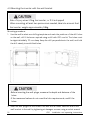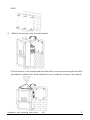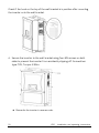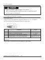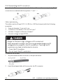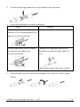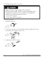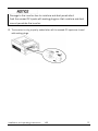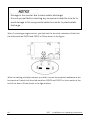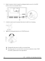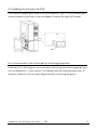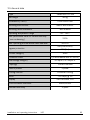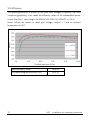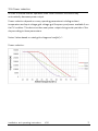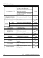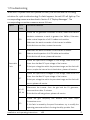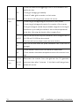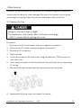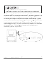
1
Contents 1 About this manual ............................................................................................... 5 1.1 Validity ........................................................................................................................ 5 1.2 Target group .............................................................................................................. 5 1.3 Symbols used in this manual .................................................................................... 6 2 Safety ..................................................................................................................7 2.1 Intended use............................................................................................................... 7 2.2 Safety standards ...................................................................................................... 7 2.3 Important safety information .................................................................................. 8 2.4 Symbols on the type label ..................................................................................... 10 2.5 Basic safety protection ........................................................................................... 11 3 Unpacking .......................................................................................................... 12 3.1 Scope of delivery .....................................................................................................12 3.2 Checking the delivery ..............................................................................................12 4 Mounting ............................................................................................................ 13 4.1 Ambient conditions ...................................................................................................13 4.2 Mounting location ....................................................................................................15 4.3 Mounting the inverter with the wall bracket ........................................................ 16 5 Electrical Connection ........................................................................................ 19 5.1 Safety ....................................................................................................................... 19 5.2 System layout of inverters without integrated DC-switch...................................21 5.3 Overview of the electrical connection area .......................................................... 22 5.4 AC connection ......................................................................................................... 23 5.4.1 Conditions for the AC connection .......................................................................................... 23 Installation and operating instructions V00 1 5.4.2 AC connection ................................................................................................................................. 23 5.4.3 Earthing protection ...................................................................................................................... 28 5.4.4 Residual current protection .................................................................................................... 29 5.4.5 Overvoltage category ................................................................................................................ 29 5.4.6 AC circuit breaker ......................................................................................................................... 30 5.5 DC connection ..........................................................................................................31 5.5.1 Conditions for the PV generator (DC) ..................................................................................31 5.5.2 Assembling the DC connectors ............................................................................................ 32 5.5.3 Disassembling the DC connectors ...................................................................................... 34 5.5.4 Connecting the PV array ........................................................................................................... 36 6 Communication ................................................................................................ 38 6.1 Monitoring system ..................................................................................................38 6.2 Communication Connection ...................................................................................39 6.2.1 Communication Overview.......................................................................................................... 39 6.2.2 Connection type for RS485-HD ............................................................................................ 40 6.2.3 Connection type for RS422 ..................................................................................................... 43 6.3 Updating the firmware via RJ45 ............................................................................ 47 6.4 Communication with a third party monitoring equipment ................................... 47 7 Commissioning ................................................................................................. 48 7.1 Electrical checks ......................................................................................................48 7.2 Mechanical checks ..................................................................................................49 7.3 Start-Up ...................................................................................................................49 8 Disconnecting the Inverter from Voltage Sources ....................................... 50 9 Operating ........................................................................................................... 51 9.1 Overview of the control panel.................................................................................51 9.2 LED indicators ......................................................................................................... 52 9.3 Display messages................................................................................................... 53 2 V00 Installation and operating instructions 9.4 Display .................................................................................................................... 55 9.4.1 Overview of menu structure ................................................................................................... 55 9.4.2 Initial page .......................................................................................................................................... 56 9.4.3 Unlocking page ............................................................................................................................... 56 9.4.4 Home page ........................................................................................................................................ 56 9.4.5 Operation information .................................................................................................................57 9.4.6 Main menu .........................................................................................................................................58 9.4.7 Historical data .................................................................................................................................58 9.4.8 Event log ............................................................................................................................................ 59 9.4.9 Date &Time setting ...................................................................................................................... 59 9.4.10 Language setting .........................................................................................................................60 9.4.11 Contrast setting .............................................................................................................................60 9.4.12 Safety regulations setting ....................................................................................................... 61 9.4.13 Overload Setting .......................................................................................................................... 62 9.4.14 Active power control ................................................................................................................ 62 9.4.15 Reactive power control ........................................................................................................... 62 9.4.16 PV Mode Setting .......................................................................................................................... 63 9.4.17 EEG Setting ...................................................................................................................................... 63 9.4.18 Communication Setting............................................................................................................ 64 9.4.19 Device information ..................................................................................................................... 64 9.4.20 Clear the historical data ......................................................................................................... 65 10 Technical data ................................................................................................. 66 10.1 DC input data ..........................................................................................................66 10.2 AC output data ...................................................................................................... 67 10.3 Safety protection ................................................................................................. 68 10.4 General data ..........................................................................................................69 10.5 Efficiency ............................................................................................................... 70 10.6 Power reduction ..................................................................................................... 71 10.7 Tools and torque ................................................................................................... 72 Installation and operating instructions V00 3 11 Troubleshooting .............................................................................................. 73 12 Maintenance .................................................................................................... 75 12.1 Replace the fuse..................................................................................................... 75 12.2 Cleaning the contacts of the DC switch ............................................................... 76 12.3 Cleaning the heat sink ........................................................................................... 76 12.4 Maintaining the fans .............................................................................................. 76 13 Recycling and disposal ................................................................................... 78 14 Warranty ......................................................................................................... 78 15 Contact ............................................................................................................ 79 4 V00 Installation and operating instructions 1 About this manual General Notes The Zeverlution Pro 33K is a transformerless three-phase inverter with two MPP trackers. It converts the direct current (DC) from a photovoltaic (PV) array to grid-compliant alternating current (AC) and feeds it into the utility grid. 1.1 Validity This manual describes the mounting, installation, commissioning and maintenance of the following Zeversolar inverter: Zeverlution Pro 33K. Observe all documentation that accompanies the inverter. Keep them in a convenient place and available at all times. 1.2 Target group This manual is for qualified electricians only who must perform the tasks exactly as described. All persons installing inverters must be trained and experienced in general safety which must be observed when working on electrical equipment. Installation personnel should also be familiar with local requirements, rules and regulations. Installation and operating instructions V00 5 1.3 Symbols used in this manual The safety precautions and general information used in this manual are as follows: DANGER indicates a hazardous situation which, if not avoided, will result in death or serious injury. WARNING indicates a hazardous situation which, if not avoided, can result in death or serious injury. CAUTION indicates a hazardous situation which, if not avoided, can result in minor or moderate injury. NOTICE indicates a situation which, if not avoided, can result in property damage. INFORMATION provides tips which are valuable for the optimal installation and operation of the inverter. 6 V00 Installation and operating instructions 2 Safety 2.1 Intended use 1. Zeverlution Pro 33K is suitable for indoor and outdoor use. 2. Zeverlution Pro 33K must only be operated with PV arrays (PV modules and cabling) of protection class II, in accordance with GB/T 20047.1. Do not connect any sources of energy other than PV modules to the inverter. 3. Zeverlution Pro 33K inverters can only be connected with photovoltaic arrays whose equivalent capacitance to ground is less than 2.0μF. 4. When the PV modules are exposed to light, a DC voltage is supplied to this equipment. 5. When designing the PV system, ensure that the values comply with the permitted operating range of all components at all times. The free design program (http://www.zeverplan.com ) will assist you. 6. This inverter supports the grid forms shown in detail as follows: TN-S, TN-C, TN-C-S, TT. In terms of TT, the effective value of UN_PE must be less than 20V. TN-S TN-C Transformer L1 TN-C-S Transformer L1 TT Transformer L1 Transformer L1 L2 L2 L2 L3 L3 L3 L3 N PEN N N PE PE PE PE Zeverlution Pro 33K L2 PE Zeverlution Pro 33K Zeverlution Pro 33K PE Zeverlution Pro 33K 2.2 Safety standards Zeverlution Pro 33K inverter has obtained the Golden Sun Certificate awarded by CQC. Zeverlution Pro 33K complies with the European standard of low voltage appliance 2006/95/EC and EMC standard 2004/108/EC and it has a CE mark on the label. For more information about safety standards in other countries and regions, please visit the website: www.zeversolar.com. Installation and operating instructions V00 7 2.3 Important safety information Danger to life due to high voltages of the PV array! When exposed to sunlight, the PV array generates dangerous DC voltage which is present in the DC conductors and the live components of the inverter. Touching the DC conductors or the live components can lead to lethal electric shocks. If you disconnect the DC connectors from the inverter under load, an electric arc may occur leading to electric shock and burns. • Do not touch non-insulated cable ends. • Do not touch the DC conductors. • Do not touch any live components of the inverter. • Have the inverter mounted, installed and commissioned only by qualified persons with the appropriate skills. • If an error occurs, have it rectified by qualified persons only. • Prior to performing any work on the inverter, disconnect it from all voltage sources as described in this document (see Section 8 "Disconnecting the Inverter from Voltage Sources", page 50). Risk of injury due to electric shock and fire caused by high leakage current! • The inverter must be reliably grounded in order to protect property and personal safety. 8 V00 Installation and operating instructions Risk of injury due to hot heat sink! • The heat sink may get hot during operation. Do not touch! Grounding the PV array! • Comply with local regulations for grounding the PV array. We suggest that the frames of the PV modules must be reliably grounded. • Do not ground any of the terminals of the PV module strings. Installation and operating instructions V00 9 2.4 Symbols on the type label Symbol Explanation Beware of high voltage and operating current. The inverter operates at high voltage and current. Work on the inverter must only be carried out by skilled and authorized electricians. Beware of hot surfaces. The inverter can get hot during operation. Avoid contact during operation. Do not dispose of this inverter with household waste. For more information on disposal, please refer to Section 13 “Recycling and disposal”. CE mark. The inverter complies with the requirements of the applicable EC guidelines. Golden Sun Certificate awarded by CQC. certification mark for solar energy product of CQC. Capacitors discharge. Before opening the covers, the inverter must be disconnected from the grid and PV array. Wait at least 5 minutes to allow the energy storage capacitors to fully discharge. Refer to the manual accompanying the inverter. Risk of danger, warning and caution. Safety information important for human safety. Failure to observe the safety information in this manual may result in injury or death. 10 V00 Installation and operating instructions 2.5 Basic safety protection We provide the following safety protection: 1) Over-voltage, under-voltage protection; 2) Over-frequency, under-frequency protection; 3) Over-temperature monitoring; 4) Residual current monitoring; 5) Insulation monitoring; 6) Active islanding protection (non-utility type); 7) Low voltage ride through (Utility type); 8) Output DC component test. Installation and operating instructions V00 11 3 Unpacking 3.1 Scope of delivery Object Description Quantity A Inverter 1 B Wall mounting bracket 1 C Mounting accessory kit 1 D Documentation 1 E DC connecter(positive) 8 F DC connecter(negative) 8 A D B C E F 3.2 Checking the delivery Check the delivery for completeness and visible external damage, such as cracks in the enclosure or in the display. Inform the responsible shipping company immediately or contact your distributor if anything is damaged or missing. 12 V00 Installation and operating instructions 4 Mounting 4.1 Ambient conditions 1. The mounting location must be inaccessible to children. 2. The mounting location should be dry, freely and safely accessible at all times without the need for any auxiliary equipment. 3. Mount the inverter in areas where it cannot be touched inadvertently. 4. The mounting method and location must be suitable for the inverter's weight and dimensions. 5. The ambient temperature should be below 40°C to ensure optimal operation. 6. In living areas, do not mount the unit on plasterboard walls or similar to avoid audible vibrations. The inverter can make noises when in use which may be perceived as a nuisance in a living area. 7. Observe the minimum clearances to walls, other inverters, or objects as shown in the diagram in order to ensure sufficient heat dissipation and sufficient space for maintaining the inverter. Direction Min. clearance Min. clearance for multiple for a single inverters inverter above 200mm 200mm below 500mm 500mm sides 600mm 600mm spacing 1000mm Installation and operating instructions clearances for one inverter V00 13 Recommended clearances for multiple inverters installation 8. Avoid exposing the inverter to direct sunlight, rain and snow to ensure optimal operation and extend service life. It is recommended to mount the inverter under the shaded site of the building or to mount an awning or a protection cover above the inverter. 9. 14 Do not put any objects above the inverter. V00 Installation and operating instructions 4.2 Mounting location Danger to life due to fire or explosion! • Do not mount the inverter on flammable construction materials. • Do not mount the inverter in areas where flammable materials are stored. • Do not mount the inverter in areas where there is a risk of explosion . 1. Mount the inverter vertically or tilted backwards at a maximum angle of 15°. The wall should be suitable for the weight of the inverter over a long time. 2. Never mount the inverter tilted forward or sideways. 3. Never mount the inverter horizontally. 4. Mount the inverter at eye level to allow operating status to be read at all times. 5. The electrical connection area must point downwards. Installation and operating instructions V00 15 4.3 Mounting the inverter with the wall bracket Risk of injury when lifting the inverter, or if it is dropped! When mounting, at least two persons are needed, take into account that the inverter weighs approximately 58kg. Mounting procedure: 1. Use the wall bracket as a drilling template and mark the positions of the drill holes on the wall, drill 6 holes as required using a drill with Ø10 mm bit. The holes must be approximately 70 mm deep. Keep the drill perpendicularto the wall, and hold the drill steady to avoid tilted holes. •Before inserting the wall plugs, measure the depth and distance of the holes. •If the measured values do not meet the hole requirements, redrill the holes. 2. Insert six wall plugs into the holes in the wall with a rubber hammer and fix the wall bracket to the wall by tightening six hexagon screws, using a socket wrench 16 V00 Installation and operating instructions SW10. 3. Mount the inverter onto the wall bracket. If the inverter is to be transported and lifted with a crane, screw two eye bolts M10 (provided by installer) into the threads which are located on the top of the inverter. Installation and operating instructions V00 17 Check if the hook on the top of the wall bracket is in position after mounting the inverter onto the wall bracket. 4. Secure the inverter to the wall bracket using four M5 screws on both sides to prevent the inverter from accidently slipping off. Screwdriver type: T25, Torque: 2.5Nm. Dismantle the inverter in reverse order. 18 V00 Installation and operating instructions 5 Electrical Connection 5.1 Safety Danger to life due to high voltages of the PV array! When exposed to sunlight, the PV array generates dangerous DC voltage which is present in the DC conductors and the live components of the inverter. Touching the DC conductors or the live components can lead to lethal electric shocks. If you disconnect the DC connectors from the inverter under load, an electric arc may occur leading to electric shock and burn. • Do not touch non-insulated cable ends. • Do not touch the DC conductors. • Do not touch any live components of the inverter. • Have the inverter mounted, installed and commissioned only by qualified persons with the appropriate skills. • If an error occurs, have it rectified by qualified persons only. • Prior to performing any work on the inverter, disconnect it from all voltage sources as described in this document (see Section 8 "Disconnecting the Inverter from Voltage Sources", page 50). Risk of injury due to electric shock! • All electrical connections must be connected in accordance with national and local electrical standards, and obtaining approval from local grid operator. Installation and operating instructions V00 19 Risk of injury due to electric shock! • The external protective earthing conductor is connected to the inverter’s protective earthing terminal through an AC terminal block, ensure the connection is reliable. • When connecting, connect the AC terminal block first to ensure the inverter earthing and then connect the DC inputs. • When disconnecting, disconnect the DC inputs first and then disconnect the AC terminal block. Damage to the inverter due to electrostatic discharge! • Touching electronic components can cause damage to or destroy the inverter through electrostatic discharge. • Ground yourself before touching any component inside. 20 V00 Installation and operating instructions 5.2 System layout of inverters without integrated DC-switch Local standards or codes may require that PV systems are fitted with an external DC-switch. The DC-switch must be able to safely disconnect the open-circuit voltage of the PV array plus a safety reserve of 20%. Every MPPT input must pass the DC-switch, so that it is isolated from the DC side of the inverter. We recommend the following electrical connection: Installation and operating instructions V00 21 5.3 Overview of the electrical connection area Position 22 Designation A DC-switch (optional) B DC connectors, input 1 C DC connectors, input 2 D COM 2 (for connecting the monitoring device) E External protection earthing terminal F COM 1 (for connecting the monitoring device) G AC output V00 Installation and operating instructions 5.4 AC connection Danger to life due to high voltages in the inverter! • Before establishing the electrical connection, ensure that the AC circuit-breaker is switched off. 5.4.1 Conditions for the AC connection Cable Requirements The grid connection is established using five conductors (L1, L2, L3, N, and PE). We recommend the following specifications for copper wire. No. Description Value A External diameter 19…28 mm B Conductor cross-sectional area 10…25mm C Stripping length of the insulated conductors D Stripping length of the cable’s outer sheath 2 16 mm Maximum. 80 mm The PE insulated conductor must be at least 5 mm longer than the L and N conductors Notes: Larger cross-sections should be used for longer cables. Installation and operating instructions V00 23 The conductor cross-section should be dimensioned to avoid power loss in cables exceeding 1% of rated output power. The maximum cable lengths depend on the conductor cross-section as follows: Conductor cross-section Maximum cable length 10mm² 22 m 16mm² 36 m 25mm² 56 m Zeverlution Pro 33K The required conductor cross-section depends on the inverter model, ambient temperature, routing method, cable type, cable losses, applicable installation requirements (installation location) of the country of installation, etc. 24 V00 Installation and operating instructions 5.4.2 AC connection Damage to the inverter due to electrostatic discharge! • Touching electronic components can cause damage to or destroy the inverter through electrostatic discharge. • Ground yourself before touching any component inside. Damage to the seal of the cover by opening the cover of the inverter in sub-zero conditions! • When opening the cover of the inverter in sub-zero conditions, the water proof sealing of the cover may be damaged. This can lead to moisture entering the inverter. • Do not open the inverter at ambient temperatures lower than -5℃. • Do open the inverter if a layer of ice has formed on the seal of the cover in sub-zero condition, remove it prior to opening the inverter (e.g. by melting the ice with warm air). Observe the applicable safety regulations. Procedure: 1. Switch off the AC circuit-breaker and secure it against being inadvertently switched back on. 2. Loosen the screws of the lower cover of the inveter using a screwdriver (type: T25). Installation and operating instructions V00 25 Loosen the screws of the lower cover! •During loosening the screws of the lower cover, it is not necessary to take off the screws, which can remain on the lower cover and will not fall off. 3. Strip the cable insulation as follows: Strip the cable insulation by 80mm (as D shown), shorten L1, L2, L3 and N, and make them 5mm shorter than PE conductor. Then strip each conductor insulation by 16mm (as C shown). Insert the bared conductor into the cord end terminal and crimp the contact, customer needs to prepare the cord end terminals in advance. 26 V00 Installation and operating instructions 4. Insert the crimped conductors L1, L2, L3, N and PE into the corresponding AC terminals through the cable gland and tighten the screws on the terminal block, using a flat blade screwdriver (blade size: 1.0 x 5.5mm) with torque 3.0Nm. Five conductors must be inserted into the corresponding holes of the AC terminal block! Otherwise it may cause damages to the inverter. The warranty does not cover the aforementioned damage. 5. Tighten AC cable gland swivel nut (SW46) by hand. Pre-screw 4 screws in lower cover and tighten them in the sequence (1-2-3-4). Screwdriver type: T25, torque: 2.5Nm. Installation and operating instructions V00 27 5.4.3 Earthing protection If required, the grounding terminal at the right bottom of the inverter can be used to connect a second protective conductor or as equipotential bonding with a screwdriver (Type: T25), torque: 2.5Nm. Information on earthing components is shown in the table below: Information on grounding components: No. 28 Position Description 1 M5 screw Delivered with the inverter 2 OT terminal (M5) Provided by installer 3 Yellow/green earthing cable 10-25mm V00 2 Installation and operating instructions 5.4.4 Residual current protection The inverter is equipped with a residual current monitoring unit (RCMU) comprising a differential current sensor and relevant detecting circuits, which fulfills the requirements of DIN VDE 0100-712 (IEC60364-7-712:2002). Therefore an external residual current device (RCD) is not required. If an external RCD needs to be installed because of local regulations, an RCD type A or type B can be installed as an additional safety measure. The residual current monitoring unit (RCMU) integrated in the inverter detects both AC & DC currents. The function of the residual current monitoring unit (RCMU) has been tested in accordance with IEC 62109-2. Refer to the following information in case an external RCD is needed! • If an external residual current device (RCD) is required in a TT or TN-S system, install a residual current device which activates at a residual current of 200mA or higher. • For each connected inverter, a rated residual current of 200mA has to be provided. The rated residual current of the RCD must be equal to at least the sum of the rated residual currents of the connected inverters. That means that, if, for example, two transformerless inverters are connected, the rated residual current of the RCD must be at least 400mA. 5.4.5 Overvoltage category The inverter can be deployed in grids of overvoltage category III or lower, as defined under IEC 60664-1. This means that it can be directly connected to the grid-connection point in a building. In installations involving long outdoor cable routing, additional overvoltage-reducing measures must be taken so that the grid overvoltage category at the connecting point is reduced from category IV to III. Installation and operating instructions V00 29 5.4.6 AC circuit breaker Danger to life due to fire! • You must protect each inverter with an individual AC circuit breaker in order to ensure that the inverter can be disconnected safely. No consumer load should be applied between the AC circuit breaker and the inverter. Use dedicated circuit breakers with load switch functionality for load switching. The selection of the AC circuit breaker rating depends on the wiring design (wire cross-section area), cable type, wiring method, ambient temperature, inverter current rating, etc. Derating of the AC circuit breaker rating may be necessary due to self-heating or if exposed to heat. The maximum output current of the inverters can be found in the following table. Type Zeverlution Pro 33K Max. output current 48A Recommended fuse type gL/gG or comparable automatic circuit breaker rating 30 V00 63A Installation and operating instructions 5.5 DC connection Danger to life due to high voltage in the inverter! • Before connecting the PV generator, ensure that the DC switch is switched off and that it cannot be reactivated. • Do not disconnect the DC connectors under load. 5.5.1 Conditions for the PV generator (DC) • PV modules of the connected strings must be of: –the same type –the same number of series-connected PV modules –identical alignment –identical tilt • The connection cables of the PV modules must be equipped with the connectors included in the scope of delivery. • At the DC input of the inverter, the following limits must not be exceeded: Type Max. DC voltage* Max. DC current Max. short-circuit current 1000V 34A/34A 51A/51A Zeverlution Pro 33K *) On the coldest day based on statistical records, the open-circuit voltage of the PV array must never exceed the maximum input voltage of the inverter. • The positive connection cables of the PV modules must be equipped with the positive DC connectors. • The negative connection cables of the PV modules must be equipped with the negative DC connectors. • At an ambient temperature over 10℃, the open-circuit voltage of the PV strings must not exceed 90% of the maximum DC input voltage of the inverter. This prevents the voltage from exceeding the maximum DC input voltage of the inverter at lower ambient temperatures. Installation and operating instructions V00 31 5.5.2 Assembling the DC connectors Assemble the DC connectors as described below. Observe the correct polarity. The DC connectors are marked with the symbols "+" and " − ". Cable requirements: The cable must be of type PV1-F, UL-ZKLA or USE2 and comply with the following properties: External diameter: 5 mm to 8 mm Conductor cross-section: 2.5 mm²to 6 mm² Number of copper conductors: at least 7 Nominal voltage: at least 1000V Danger to life due to high voltages on DC conductors! When exposed to sunlight, the PV array generates dangerous DC voltage which is present in the DC conductors. Touching the DC conductors can lead to lethal electric shocks. • Cover the PV modules. • Do not touch the DC conductors. Proceed as the follows: 1. Strip the cable insulation as shown in the picture below. 2. 32 Insert the stripped cable all the way into the DC connector. V00 Installation and operating instructions 3. Press the clamping bracket down until it audibly snaps into place. 4. Ensure that the cable is correctly positioned: Result If the stranded wires are visible in the Measure • Proceed to step 5. chamber of the clamping bracket, the cable is correctly positioned. If the stranded wires are not visible in • Release the clamping bracket with a the chamber, the cable is not flat-blade screwdriver (blade width: 3.5 correctly positioned. mm). • Remove the cable and go back to step 1. 5. Push the swivel nut up to the thread and tighten the connector (SW15, torque: 2.0Nm). Installation and operating instructions V00 33 5.5.3 Disassembling the DC connectors Danger to life due to high voltages on DC conductors! When exposed to sunlight, the PV array generates dangerous DC voltage which is present in the DC conductors. Touching the DC conductors can lead to lethal electric shocks. • Cover the PV modules. • Do not touch the DC conductors. Proceed as the follows: 1. Unscrew the swivel nut. 2. To release the connector, insert a flat-blade screwdriver (blade width: 3.5 mm) into the side catch mechanism and lever out. 3. Carefully pull out the DC connector. 34 V00 Installation and operating instructions 4. Release the clamping bracket. To do so, insert a flat-blade screwdriver (blade width: 3.5 mm) into the clamping bracket and lever out. 5. Remove the cable. Installation and operating instructions V00 35 5.5.4 Connecting the PV array The inverter can be destroyed by overvoltage! If the voltage of the PV module exceeds the maximum DC input voltage of the inverter, it can be destroyed due to overvoltage. All warranty claims become void. • Do not connect strings with an open-circuit voltage greater than the maximum DC input voltage of the inverter. • Check the design of the PV system. Procedure: 1. Ensure that the AC circuit breaker is switched off and ensure that it cannot be accidentally reconnected. 2. Ensure that the DC switch is switched off and ensure that it cannot be accidentally reconnected. 3. Ensure that there is no ground fault in the PV array. 4. Check whether the DC connector has the correct polarity. If the DC connector is equipped with a DC cable having the wrong polarity, the DC connector must be re-connected in accordance with the right polarity. 5. Ensure that the open-circuit voltage of the PV array does not exceed the maximum DC input voltage of the inverter. 6. Connect the assembled DC connectors to the inverter until they audibly snap into place. 7. Ensure that all DC connectors are securely in place. 36 V00 Installation and operating instructions Damage to the inverter due to moisture and dust penetration! Seal the unused DC inputs with sealing plugs so that moisture and dust cannot penetrate the inverter. 8. The inverter is only properly sealed when all the unused DC inputs are closed with sealing plugs. Installation and operating instructions V00 37 6 Communication 6.1 Monitoring system The Zeverlution Pro 33K inverter is equipped with RS485 interfaces for external communication. Monitoring of multiple inverters can be achieved by connecting multiple inverters in series onto a RS485 bus, and eventually to ZeverManager. The overall length of the network cable should not exceed 1000m. The monitoring system layout for inverters is as follows: The ZeverManager connects to the inverter via the RS485 interface, and it connects to the router via Ethernet. Then you’ll be able to connect the inverter to our remote monitoring platform “Solarcloud”. You can monitor the operating status or power generation data via a smart phone or PC. The website address of the “Solarcloud” is http://solarcloud.zeversolar.com 38 V00 Installation and operating instructions For detailed information, please refer to ZeverManager user manual. CAT-5 with shield or higher leveled cable is required as the communication cable RS485 between inverter and ZeverManager. Assignment of pins on both ends of the cable shall comply with EIA/TIA568A or 568B standard. It shall be UV resistant if used outdoors. 6.2 Communication Connection 6.2.1 Communication Overview The inverter has two communication modes: RS485-HD and RS422. You may choose either communication modes with an external device. RS485-HD stands for RS485 half-duplex. To facilitate the communication wire selection, we offer two connection types: terminal blocks and RJ45 ports, as shown in figure ① and ②. The terminal blocks only support RS485-HD mode, while RJ45 ports support both RS485-HD and RS422, you can select the modes using the switch shown in figure ③. Installation and operating instructions V00 39 6.2.2 Connection type for RS485-HD Move slide switch CN901 to the position RS485-HD when using RS485-HD communication type, as shown in the figure below. 40 V00 Installation and operating instructions When RJ45 is employed as the communication port for RS485-HD, the pin assignment of RJ45 is as follows: Pin1------- RS485_A Pin2------- RS485_B Pin3------- NC Pin4------- GND Pin5------- GND Pin6------- NC Pin7------- +7V Pin8------- +7V When the terminal block is employed as the communication port for RS485-HD, the pin distribution of terminal block is as follows: cable 485 pin of terminal block RS485_A A RS485_B B GND GND Installation and operating instructions V00 41 When connecting one inverter, you need to connect the terminal resistance to the bus by switching CN909 to the ON position as shown in the figure below (Switch CN909 to ON, CN910 to OFF): When connecting multiple inverters, please move the terminal resistance slide switch (CN909) on the inverter which at the end of the bus to ON and all switch resistance slide switches of the inverters in between to OFF as shown in the figure below: Inverter in the Middle 42 Inverter at the end of the bus V00 Installation and operating instructions 6.2.3 Connection type for RS422 Firstly, switch the slide switch CN901 to RS422 as shown in the figure below: Ports except port RJ45 are not allowed to be connected when employing RS422 communication mode. The pin information for RJ45 interface is shown in the table below: Pin1------- TX_RS485A Pin2------- TX_RS485B Pin3------- RX_RS485A Pin4------- GND Pin5------- GND Pin6------- RX_RS485B Pin7------- +7V Pin8------- +7V The cable pin assignment shall comply with the EIA/TIA568A or 568B standard. When using outdoors you shall use the UV resistant cable. Installation and operating instructions V00 43 Damage to the inverter due to electrostatic discharge! Ground yourself before touching any component inside the inverter to avoid damage to the components inside the inverter by electrostatic discharge. When Connecting a single inverter, you shall set the terminal resistance of the both the slide switches CN909 and CN910 to ON as shown in the figure: When connecting multiple inverters, you shall connect the matched resistance at the bus terminal. Switch both the slide switches CN909 and CN910 on the inverter at the end of the bus to ON as shown in the figure below: 44 V00 Installation and operating instructions Inverter in the Middle Inverter at the end of bus Damage to the inverter due to moisture and dust penetration! Make sure the waterproof connectors of the communication interface are securely tightened. Connecting procedure for RJ45 connection: 1. Loosen the swivel nut of M25 cable gland for COM1, take out the filler plug in the sealing insert: Installation and operating instructions V00 45 2. Guide the network cable through the cable gland and connect it to the RJ45 socket on the communication board. 3. A cable tie can be used to prevent the network cable from loosening. 4. Tighten the cable gland swivel nut of (SW29) by hand. ● Disassemble the network cable in a reversed order. ● Operating steps for terminal blocks connection is identical to that of RJ45 connection, please refer to the steps above. 46 V00 Installation and operating instructions 6.3 Updating the firmware via RJ45 If you have to update the firmware, use a screwdriver (Type: T25) to unscrew the 4 screws located on the lower cover and update firmware through RJ45 socket. 6.4 Communication with a third party monitoring equipment Zeverlution Pro 33K supports communication with third party monitoring equipment such as Metecontrol, Solar-Log etc. For detailed operation method please refer to operation manual of the corresponding third party monitoring equipment. Installation and operating instructions V00 47 7 Commissioning Risk of injury due to incorrect installation! We strongly recommend carrying out preliminary checks before commissioning to avoid possible damage to the unit caused by faulty installation. 7.1 Electrical checks Danger to life due to the presence DC-Voltage! • Only touch the insulation of the PV array cables. • Do not touch parts of the substructure and frame of PV array. • Wear personal protective equipment such as insulating gloves. . Danger to life due to the presence of AC-Voltage! • Only touch the insulation of the AC cables. • Wear personal protective equipment such as insulating gloves. Carry out the main electrical checks as follows: 1. Check PE connection: ensure the inverter has a reliable earth connection. 2. Check the DC voltage values: check that the DC voltage of the strings does not exceed the permitted limits. 3. Check the polarity of the DC voltage: make sure the DC voltage has the correct polarity. 4. Check the PV string insulation to earth: make sure that the insulation resistance to ground is greater than 1 MOhm. 5. Check the grid voltage: check that the grid voltage at the point of connection of the inverter within the permitted values. 48 V00 Installation and operating instructions 7.2 Mechanical checks Carry out the main mechanical checks to ensure the IP protection level of the inverter: 1. Ensure that the lower cover has been securely screwed in place. 2. Use sealing caps for tight sealing of unused DC input connectors. 3. Make sure the RS485/RS422 connection has been connected securely. 4. Ensure that the cable glands have been securely screwed in place. 7.3 Start-Up After finishing the electrical and mechanical checks, switch on the AC circuit breaker and DC-switch in turn. The inverter will start up automatically. Usually there are three statuses during operation: Waiting: When the initial voltage of the strings is greater than the minimum DC input voltage but lower than the start-up DC input voltage, the inverter is waiting for sufficient DC input voltage and cannot feed power into the grid. Checking: When the initial voltage of the strings exceeds the start-up DC input voltage, the inverter will check feeding conditions at once. If there is anything wrong during checking, the inverter will switch to the “Fault” mode. Normal: After checking, the inverter will switch to “Normal” state and feed power into the grid. During periods of little or no sunlight, the inverter may continuously start up and shut down. This is due to insufficient power or input voltage generated by the PV array. If this fault occurs often, please call service. Quick Troubleshooting! If the inverter is in "Fault" mode, refer to Section 11 "Troubleshooting" in the manual. Installation and operating instructions V00 49 8 Disconnecting the Inverter from Voltage Sources Danger to life due to high voltages! The capacitors in the inverter take 5 minutes to discharge. • Wait 5 minutes before opening the cover. Before performing any work on the inverter, disconnect it from all voltage sources as described in this section. Always adhere strictly to the prescribed sequence. Procedure: 1. Disconnect the AC circuit breaker and secure against reconnection. 2. Disconnect the DC-switch and secure against reconnection. 3. Use a current clamp meter to ensure that no current is present in the DC cables. 4. Release and remove all DC connectors. Insert a flat-blade screwdriver or an angled screwdriver (blade width: 3.5 mm) into one of the slide slots and pull the DC connectors out downwards. Do not pull on the cable. 5. Loosen the screws of the lower cover using a screwdriver (T25) and remove the 4 screws. 6. Use a suitable measuring device to check that no voltage is present at the AC screw terminal block between L and N, L and PE, then use a blade screw driver (blade size: 1.0 x 5.5mm) to loosen the screws on the AC terminal block. 7. Unscrew the screws of the terminal block and the swivel nut of the cable gland, remove the AC cable. 8. Tighten the swivel nut (SW46) of the cable gland and secure the 4 screws on lower cover using a screwdriver (Type: T25, torque: 2.5 Nm). 50 V00 Installation and operating instructions 9 Operating 9.1 Overview of the control panel The inverter is equipped with a control panel which includes a liquid crystal display (LCD), three LED indicators and four touch sensing control buttons. You can view the data and set the parameters of the inverter using the buttons on the LCD display. No. Description A Display B ▲ (Up button) C ▼ (Down button) D Normal (Green LED) E Fault (Red LED) F Communication (Bicolor LED) G ESC button H Installation and operating instructions (Enter button) V00 51 9.2 LED indicators The inverter is equipped with three LED including “green”, “red” and “bicolor” which provide information about the various operating status of the inverter as follows. Green LED: The green LED is lit when the inverter is operating normally. Red LED: The red LED is lit when the inverter has stopped feeding power into the grid due to a fault. The corresponding error code will be shown on the display at the same time. Bicolor LED: The bicolor LED can blink green or red. It blinks during communication with other devices such as a ZeverManager, Solarlog, etc. The bicolor LED blinks green when the inverter is receiving commands from other devices, and blinks red when the inverter is sending response commands to the other devices. 52 V00 Installation and operating instructions 9.3 Display messages Along with the various operating states, various messages maybe shown on the display for details, see the following table. Status Error Description Causes code Initial PV voltage is between Min. DC input Waiting voltage and start-up DC input voltage of the inverter. Initializ The inverter is checking feeding conditions ation Checking after initial PV voltage exceeds start-up DC input voltage of the inverter. The inverter is checking feeding conditions Reconnect Normal Normal 1 Fault after the last fault has been solved. The inverter is operating normally. Communication fails between M-S Communication between the master and slave MCU has failed. 2 EEPROM R/W Fail Reading or writing of EEPROM fails 3 Relay Check Fault Output relay has failed. 4 DC injection High 8 AC HCT Failure 9 GFCI Device failure 10 Device Fault 11 M-S version unmatched 33 Fac Fault 34 Vac Fault Output DC feed-in exceeds the permitted upper limit. Output current sensor is abnormal. GFCI detection circuit is abnormal. Unknown Error Different software version between the master and slave MCU. The grid frequency lies outside the permitted range. The grid voltage is outside the permitted range. The utility cannot be detected, which may be 35 Utility Loss caused by no utility, grid disconnected, AC cable damage, fuse broken or island. Installation and operating instructions V00 53 36 Ground Fault 37 PV Overvoltage The residual current exceeds the permitted upper limit. The voltage of the strings exceeds the permitted upper limit. The PV generator’s insulation resistance to 38 ISO Fault 39 Fan Lock 40 Over Temp. earth is below the permitted value, or the electrical insulation inside the inverter has failed. Fault Vac differs for M-S 41 The internal temperature exceeds the permitted value. A different value of grid voltage has been detected by the master and slave MCU. Fac differs for M-S 42 43 The fan or internal circuit has failed. A different value of grid frequency has been detected by the master and slave MCU. Ground I differs for M-S 44 A different value of residual current has been detected by the master and slave MCU. DC Inj. differs for M-S A different value of DC feed-in has been detected by the master and slave MCU. The voltage of DC Bus exceeds the 46 High DC Bus 49 PV1-SPD failure PV1-SPD failure 50 PV1-SPD failure PV2-SPD failure 51 FUSE failure permitted upper limit. DC side FUSE failure The latest 10 dated failure reports on the NS protection can be read. An interruption in the supply voltage of ≤ 3s does not result in any loss of failure reports (according to VDE-AR-N 4105). 54 V00 Installation and operating instructions 9.4 Display 9.4.1 Overview of menu structure The diagram is a diagram that shows the switching relations between all pages on the LCD. unlock Slipe from ‘Down’ to ‘Esc’ to unlock Country data set Initializing... 17 22 t 180S Country data set 8 13 DE VDE-AR-N 4105 4 19/11/2013 12:23 P 17 KW Power 17654 W Etoday 123.4 KWh Etotal 15234.5 KWh Error Code:02 Temp. under -25℃ Operating information 12.3 A 12.5 A 13.1 A Statistics Event Log Settings Device Info Menu Statistics MENU STRUCTURE 0 0 h W 0.0 KWh Peak Etoday 09/11/2013 Daily Statistics Runtime 0.0 KWh h W E month 11/2013 Monthly Statistics 0 Days 0 0 h W 0.0 KWh Annual Statistics Basic Setting 0 Eyear Runtime Peak 2013 Peak E12 Runtime E43 E03 Months [1] 12/09/2013 08:45 Years Event Logs [2] 11/09/2013 17:23 E45 [3] 10/08/2013 15:23 [4] 07/07/2013 13:23 E01 Language Setting Date&Time Setting Settings [5] 02/06/2013 12:23 Basic Setting HMI:20U13B20367B.A-list02 Communication Contrast Setting Advanced Setting Device Info Communication Setting TYPE: TLC20K S/N:1234567890123456 MCU:V1.00 STD:DE VDE-AR-N 4105 Date&Time Language DD/MM/YYYY hh:mm 2013 12:34 21/11/2013 English Deutsch 简体中文 繁體中文 50 Contrast Setting Password 0 Password:0 0 0 0 P a s s w o r d 2 Password 1 Communication Please wait... Clear data? Password Incorrect password! Communication Advanced Setting Safety Setting Overload Setting Active power control Reactive power control PV Mode Setting EEG Setting Setting failed! Clearing data... 180.5 V 265.5 V 185.0 V 255.0 V 180.0 V Safety Standard: DE VDE-AR-N 4105 OVP2: OVP1: UVP1: UVP2: 12.50 S 12.50 S 12.50 S 30.50 S 10-minute mean: Overload Enable Overload Setting: Disable Active power control Enable Active power control: Disable Reactive power control Enable Reactive power control: Disable EEG PV Mode PV Mode Setting: Independent Mode Parallel Mode Enable EEG Setting: Disable 12.50 S 54.50 Hz 12.50 S 53.50 Hz 12.50 S 47.50 Hz 12.50 S 45.50 Hz Safety Press ESC to return DSP timeout! Press ESC to return Clearing complete! OFP2: OFP1: UFP1: UFP2: Safety Press ESC to return Disconnect AC side first! 55 V00 Installation and operating instructions VacL1 236.1 V IacL1 VacL2 235.5 V IacL2 VacL3 237.8 V IacL3 5798 W 10.3 A 9.8 A Operating information 1.00 Phase Leading 50.01 Hz Runtime 12 h 5802 W Ppv2 580.8 V Ipv1 579.2 V Ipv2 PF Fac Ppv1 Vpv1 Vpv2 Device Address:N Press ESC to return Communication Setting successful! Press ESC to return Communication 安规 Press ESC to return Setting timeout! . 9.4.2 Initial page When the inverter starts up, the LCD will first display an initial page that shows the current safety standard information of the inverter. The page will display for about 5 seconds and then jump to the home page automatically. Country data set DE VDE-AR-N 4105 9.4.3 Unlocking page When the backlight of the LCD has turned off, press any key and the unlocking interface prompts. You need to touch the “downward” arrow and “Esc” in sequence to unlock and enter the home page for operation. 9.4.4 Home page The home page shows some of the most important operational data of inverter such as the output power, daily energy generation, total power generation, an error code, and the power graph etc. A ▶05/05/2015 12:23 Code:02 ▶ ▶ 33 KW F G I H ▶ E ▶Error 60S ▶ P Power B ▶ 31329 W Etoday C ▶ 123.4 KWh Etotal D ▶ 15234.5 KWh t 4 8 13 17 22 The LCD will switch to standby mode and jump to the home page automatically, and the backlight will turn off when there is no button operation in 30 seconds. 56 V00 Installation and operating instructions No. Description A Date& Time B Output power C Daily power generation D Total power generation E Error code(*), for details see article 9.3 F Checking countdown G Operating status: H Trend map of output power from 4:00 to 22:00 I waiting, operating, fault Load limit Enable Indication (*) The operating temperature of the inverter can’t be lower than -25°C. The inverter will goes into fault mode and stops power generation when the temperature is lower than -25°C. The display will show the error message “Temp. under -25°C”. 9.4.5 Operation information These two pages show the operational information on the AC & DC side of the inverter respectively. Switch between these 3 pages by pressing the “▲” or “▼” button. Running Info D 1.00 Phase Leading 50.01 Hz Runtime 12 h E F ▶ ▶ B ▶PF C ▶Fac ▶ VacL3 237.8 V IacL2 No. Description A Grid voltage B Power factor C Grid frequency D Output current Installation and operating instructions G ▶ Vpv1 Vpv2 645.8 V Ipv1 638.2 V Ipv2 25.3 A 26.8 A I H ▶Ppv1 16634 W Ppv2 16653 W J V00 ▶ 46.3 A 46.5 A 46.1 A A ▶VacL2 235.5 V IacL2 ▶ VacL1 236.1 V IacL1 Running Info 57 E Phase, leading or lagging F Running time G DC input voltage H DC input power 1 I DC input current J DC input power 2 9.4.6 Main menu Press the " " button to enter the main menu from the home page. Press the "▼" or "▲" button to select the menu item. Press the " " button to confirm, enter the sub-page chosen. Press the "ESC" button to return to the home page. Menu Statistics Event Log Settings Device Info 9.4.7 Historical data Press the "▲" or "▼" button to select the "Statistics" item of main menu and press " " button to confirm. Press the "▲" or "▼" button to select Daily historical data, Monthly historical data or Yearly historical data. Press the " " button to confirm. Press the "▲" button one time to display the previous historical record. Press the "▼" button one time to display the next historical record. Press the "ESC" button to return to the menu. 58 V00 Installation and operating instructions Statistics 09/11/2013 Day Statistics Days Etoday Months Peak 0 W Years Runtime 0 h 0.0 KWh 9.4.8 Event log Press the "▲" or "▼" button to select the "Event Log" item of main menu and press the " " button to confirm. Press the "▲" or "▼" button to check the fault messages. Press the "ESC" button to return to the main menu. Event Logs E12 [2] 11/09/2013 17:23 E03 [3] 10/08/2013 15:23 E43 [4] 07/07/2013 13:23 E45 [5] 02/06/2013 12:23 E01 Object ▶ A ▶[1] 12/09/2013 08:45 B Description A Date and time of the fault B Error code 9.4.9 Date &Time setting Enter the sub-menu “Basic Setting” and press the "▼" or "▲" button to select the "Date &Time Setting" item of the “Settings” sub-menu and press the " " button to confirm. Use the "▲"or "▼"button to set the year, month, day, hour and minute one by one. Press the " " button to confirm. Press the "ESC" button to return to the Basic Setting page. Installation and operating instructions V00 59 Date&Time DD/MM/YYYY hh:mm 2013 12:23 19/11/2013 9.4.10 Language setting Enter the sub-menu “Basic Setting” and press the "▼" or "▲" button to select the "Language Setting" and press the " " button to confirm. Use the "▲" or "▼" to choose the language. Press the " " button to confirm. Press the "ESC" button to return to the Basic Setting page. Language English Deutsch 简体中文 繁體中文 9.4.11 Contrast setting Enter the sub-menu “Basic Setting” and press the "▼" or "▲" button to select the "Contrast Setting" and press the " " button to confirm. Use the "▲" or "▼" to choose the LCD contrast. Press the " " button to save. Press the "ESC" button to return to the Basic Setting page. Contrast 50 60 V00 Installation and operating instructions 9.4.12 Safety regulations setting Enter the sub-menu “Advanced Setting” and press the " " button to input the password. The password is required if you want to change some parameters. Please get the correct password from the service engineer. Enter the correct password and " " to enter the advanced setting sub-menu page. Then select the “Safety Setting” item and press the " " button then enter the safety parameters page. Password 0 0 0 0 Password:0 Advanced Setting Safety Setting Overload Setting Active power control Reactive power control PV Mode Setting EEG Setting At the safety regulation parameter page, use the "▲" or "▼" button to modify the selected parameter and confirm with the " " button. Then modify the next parameter in turn. Parameter modification is finished after the Enter key is pressed. Press the "ESC" button to cancel. Safety Standard: DE VDE-AR-N 4105 OVP2: OVP1: UVP1: UVP2: 265.5 185.0 255.0 180.0 V V V V 10Min-Mean: 180.5 V Safety OFP2: OFP1: UFP1: UFP2: 54.50 53.50 47.50 45.50 Hz Hz Hz Hz There are two pages for safety regulation parameters setup. After modifying the last parameter of the first page, the page will automatically jump to the second page. The safety of the grid may be influenced due to the wrong safety setting! •The default parameters settings comply with the local regulations. •Don’t change the values of the default safety regulation values unless permitted by the utility provider! Installation and operating instructions V00 61 9.4.13 Overload Setting Enter the sub-menu “Advanced Setting” and press the "▼" or "▲" button to select the "Overload Setting" and press the " " button to set the status. Use the "▲" or "▼" to choose “Enable” or “Disable”. Press the " " button to confirm this function is effective on the inverter. Press the "ESC" button to return to the Advanced Setting page. Overload Overload Setting: Disable Enable 9.4.14 Active power control Enter the sub-menu “Advanced Setting” and press the "▼" or "▲" button to select the "Active power control" and press the " " button to set the status. Use the "▲" or "▼" to choose the active power of the status. Press the " " button to confirm this function is effective on the inverter. Press the "ESC" button to return to the Advanced Setting page. Active power control Active power control: Disable Enable 9.4.15 Reactive power control Enter the sub-menu “Advanced Setting” and press the "▼" or "▲" button to select the "Reactive power control" and press the " " button to set the status. Use the "▲" or "▼" to choose the reactive power of the status. Press the " " button to confirm this function is effective on the inverter. Press the "ESC" button to return to the Advanced Setting page. 62 V00 Installation and operating instructions Reactive power control Reactive power control: Disable Enable 9.4.16 PV Mode Setting Enter the sub-menu “Advanced Setting” and press the "▼" or "▲" button to select the "PV Mode Setting" and press the " " button to set the status. Use the "▲" or "▼" to choose the PV Mode. Press the " " button to confirm this function is effective on the inverter. Press the "ESC" button to return to the Advanced Setting page. PV Mode PV Mode Setting: Independent Mode Parallel Mode 9.4.17 EEG Setting Enter the sub-menu “Advanced Setting” and press the "▼" or "▲" button to select the "EEG Setting" and press the " " button to set the status. Use the "▲" or "▼" to choose the EEG of the status. Press the " " button to confirm this function is effective on the inverter. Press the "ESC" button to return to the Advanced Setting page. EEG EEG Setting: Disable Enable Installation and operating instructions V00 63 9.4.18 Communication Setting Enter the sub-menu “Communication Setting” and press the "▼" or "▲" button to select the address and press the " " button to set the modbus communication address. Use the "▲" or "▼" to choose the address. Press the " " button to confirm this function is effective on the inverter. Press the "ESC" button to return to the menu. Communication Device Address:N 9.4.19 Device information Press the "▼" or "▲" button to select the "Device Info" item of the main menu and press the " " button to confirm, then you can check the basic information of the device. Press the "ESC" button to return to the menu. Device Info TYPE: ZL Pro 33K S/N:1234567890123456 MCU:V1.00 HMI:20U13B20367B.A-list02 STD:DE VDE-AR-N 4105 64 V00 Installation and operating instructions 9.4.20 Clear the historical data Enter the "Advanced Setting" page, enter the correct password, and enter the data clear page. Clear Data? Press the " " button to confirm to clear the historical data. Press the “ESC” button to cancel. Wait a Second... Installation and operating instructions Clear Completed! V00 65 10 Technical data 10.1 DC input data Type Zeverlution Pro 33K Rated DC input power(Pdc.r) 34000 W Max. recommended DC input power 40800 W Max. DC input voltage 1000 V Rated DC input voltage (1) 620 V MPP voltage range 270 … 950 V Full load MPP voltage range 500 … 800 V Start-up DC input voltage 300 V Min feed-in DC voltage 270 V Max. DC input current (input 1/input 2) 34A/34A Isc PV, absolute max.(input 1/ input 2) 51A/51A Max. inverter back feed current to the array 0A Number of MPPT trackers 2 Strings per MPP tracker 4/4 Turn on power 25 W DC-switch Optional (1) When DC input Voltage is higher than 1000V, the inverter will alarm an error. When DC input Voltage is below 950V, the inverter begins to check and connect to gird. 66 V00 Installation and operating instructions 10.2 AC output data Type Zeverlution Pro 33K Power connection Three phase Rated output power Max. output active power 30000W (1) Max. output apparent power 33000W (2) 33000VA 3/N/PE, 220/380V Rated grid voltage 3/N/PE, 230/400V 3/N/PE, 240/415V (3) AC voltage range 160 V to 300 V Operating range at AC mains frequency 50 Hz 45 Hz to 55 Hz (4) Operating range at AC mains frequency 60 Hz 55 Hz to 65 Hz (4) Max. output current Power VDE-AR-N 4105 factor Other safety regulations 3×48A 0.85ind - 0.85cap >0.97 at 20% load, >0.99 at 100% load 300V,63A, Recommended AC circuit breaker TYPE C circuit breaker Total current harmonic wave <3% (rated power) distortion factor (THD) Evening loss <1W Standby loss < 12 W (1) Max. output active power is 30000W for Australia market. (2) Max. output apparent power is 30000VA for Australia market. (3)The AC voltage range should comply with the local safety standards. (4)The AC frequency range should comply with the local safety standards. Installation and operating instructions V00 67 10.3 Safety protection Type Zeverlution Pro 33K Internal overvoltage protection Integrated DC insulation monitoring Integrated DC feed-in monitoring Integrated Grid monitoring Integrated Residual current monitoring Integrated (according to EN 62109-2) Islanding protection Integrated (Three-phrase monitoring) EMC immunity EN61000-6-1, EN61000-6-2 EMC emission EN61000-6-3, EN61000-6-4 Utility interference EN61000-3-2, EN61000-3-11, EN61000-3-3 EN61000-3-12 INFORMATION If you choose the standard VDE-AR-N 4105, please refer to information below. • If a central NS protection device is used for PV power generation station, then the value of the rise-in-voltage protection U > of 1.1Un presented in the integrated NS protection can be changed, but need password. 68 V00 Installation and operating instructions 10.4 General data Type Zeverlution Pro 33K Net weight 58 Kg Dimensions (L×W×D) 710×510×260 mm Mounting environment Indoor and Outdoor Mounting recommendation Wall bracket Operating temperature range -25… +60℃ Max. permissible value for relative humidity ( non-condensing ) Max. operating altitude above mean sea level 100% 2000 m IP65(Electronics) Ingress protection IP55(Fan) Climatic category 4K4H Protection class I ( in accordance with IEC 62103) Overvoltage category DC input: II, AC output: III Topology Transformerless Feed-in phases 3 phase Cooling method Forced air cooling Noise < 60 dB(A) @ 1m Display 240×160Pixels, LCD Communication interfaces RS485/RS422 Standard warranty Installation and operating instructions 5 years V00 69 10.5 Efficiency The operating efficiency is shown for the three input voltages (Vmppmax, Vdc,r and Vmppmin) graphically. In all cases the efficiency refers to the standardized power output (Pac/Pac,r). (according to EN 50524 (VDE 0126-13): 2008-10, cl. 4.5.3). Notes: Values are based on rated grid voltage, cos(phi) = 1 and an ambient temperature of 25℃. 70 Max. efficiency, ηmax 98.5 % European weighted efficiency, ηEU 98.2 % V00 Installation and operating instructions 10.6 Power reduction In order to ensure inverter operation under safe conditions, the device may automatically decrease power output. Power reduction depends on many operating parameters including ambient temperature and input voltage, grid voltage, grid frequency and power available from the PV modules. This device can decrease power output during certain periods of the day according to these parameters. Notes: Values based on rated grid voltage and cos(phi) = 1. Power reduction: Installation and operating instructions V00 71 10.7 Tools and torque Tools Object Torque Screws for the lower cover Screws for second protective Trox screwdriver, T25 grounding connection 2.5Nm Screws for connecting the inverter and wall bracket Flat-head screwdriver, blade size: 1.0×5.5mm Flat-head screwdriver, blade width: 3.5mm Socket wrench 3.0Nm Sunclix DC connector SW29 swivel nut of the M25 cable gland 4.0Nm SW46 swivel nut of the M40 cable gland 7.5Nm SW10 Hexagon screw for wall bracket Wire stripper Crimping tools Hammer drill, drill bit of Ø10 Rubber hammer Crimp power cables Drill holes on the wall Hammer wall plugs into holes Cut power cables Multimeter Check electrical connection Marker Mark positions of drill holes Safety goggle Anti-dust respirator Hand-tight Peel cable jackets Cable cutter ESD glove 72 Screw terminal block for AC cable Wear ESD glove when opening the inverter Wear safety goggle during drilling holes Wear anti-dust respirator during drilling holes V00 Installation and operating instructions 11 Troubleshooting When the PV system does not operate normally, we recommend the following solutions for quick troubleshooting. If a fault happens, the red LED will light up. The corresponding causes are described in Section 9.3 "Display Messages". The corresponding corrective measures are as follows: Object Error Corrective measures Code •Check the PV generator’s insulation to earth, make sure that the insulation resistance to earth is greater than 1MOhm; Otherwise, 38 make a visual inspection of all PV cables and modules. •Make sure the earth connection of the inverter is reliable. If this fault occurs often, contact the service. •Make sure the earth connection of the inverter is reliable. 36 •Make a visual inspection of all PV cables and modules. If this fault is still shown, please call service. •Check the open-circuit voltages of the strings, make sure it is Resumable Fault 46 lower than the Max. DC input voltage of the inverter; If the input voltage lies within the permitted range, and the fault still occurs, maybe the internal circuit has broken, please call service. •Check the open-circuit voltages of the strings, make sure it is 37 lower than the Max. DC input voltage of the inverter. If the input voltage lies within the permitted range and the fault still occurs, please call service. 41, 42 43, 44 •Disconnect the inverter from the grid and the PV generator, reconnect them after 3 minutes. If this fault is still being shown, please call service. •Check the grid frequency and observe how often major 33 fluctuations occur. If this fault is caused by frequent fluctuations, try to modify the operating parameters after informing the utility provider first. Installation and operating instructions V00 73 •Check the fuse and the triggering of the AC circuit breaker in the distribution box. 35 •Check grid voltage, grid usability. •Check AC cable, grid connection on the inverter. Resumable If this fault is still being shown, please call service. Fault •Check the grid voltage and grid connection on the inverter. 34 •Check the grid voltage at the point of connection of the inverter. If the grid voltage is outside the permissible range due to local grid conditions, try to modify the values of the monitored operational limits after informing the electric utility company first. Open the box and check the power distribution, see if the signal cable of 49,50 PV1-SPD and PV2-SPD has disconnected. If the fault still occurs, please contact the service hotline. 51 Open the box and check the power distribution, see if the FUSE is damaged. •Check whether the airflow to the heat sink is obstructed. 40 •Check whether the ambient temperature around the inverter is too high. Permanent Fault 74 1,2,3,4 Disconnect the inverter from the grid and the PV generator, 8,9,10, reconnect them after 3 minutes. If this fault is still being shown, 11, 39 please call service. V00 Installation and operating instructions 12 Maintenance Normally, the inverter needs no maintenance or calibration. Regularly inspect the inverter and the cables for visible damage. Disconnect the inverter from all power sources before cleaning. Clean the enclosure and display with a soft cloth. 12.1 Replace the fuse Danger to life due to high voltage! The capacitors in the inverter take 5 minutes to discharge. • Wait 5 minutes before opening the cover. Procedure: 1. Disconnect the AC circuit breaker and secure against reconnection. 2. Disconnect the DC-switch and secure against reconnection. 3. Remove all DC connectors. 4. Wait 5 minutes. 5. Loosen the screws of the lower cover using a screwdriver (T25) and remove the lower cover. 6. Check using multimeter to identify the blown fuse and check the corresponding PV strings. 7. Remove the blown fuse and insert the new fuse into the fuse holder. 8. Reassemble the lower cover and restart the inverter. Installation and operating instructions V00 75 12.2 Cleaning the contacts of the DC switch Clean the contacts of the DC switch annually. Perform cleaning by cycling the switch to “1” and “0” positions 5 times. The DC switch is located at the lower left of the enclosure. 12.3 Cleaning the heat sink Risk of injury due to hot heat sink! • The heat sink may exceed 70℃during operation. Do not touch the heat sink during operation. • Wait approx. 30 minutes before cleaning until the heat sink has cooled down. Clean the heat sink with compressed air, soft brush or vacuum cleaner. Do not use aggressive chemicals, cleaning solvents or strong detergents. For proper function and long service life, ensure free air circulation around the heat sink. 12.4 Maintaining the fans Risk of injury due to hot heat sink! • The heat sink may exceed 70℃during operation. Do not touch the heat sink during operation. • Wait approx. 30 minutes before maintenance until the heat sink has cooled down. 76 V00 Installation and operating instructions Damage to the fan due to compressed air! • Clean the fan only with a soft brush, a paint brush, or a damp cloth. This device is equipped with two fans located on the right side. If the fan does not run normally or makes any unusual noise, clean the fans or replace the broken fans. To do so, disconnect the inverter from all power sources, and wait approx. 30 minutes until the inverter has cooled down. Unscrew the fan bracket (Screwdriver type: T25) and remove the fans out of the inverter by pressing on the cable locking hooks of the fans. Loosen the screws securing the fan by a Phillips screwdriver. Then the fan can be cleaned using a soft cloth or a brush or be replaced. After maintenance, reassemble the fans back(Torque: 0.7Nm)and tighten 4 screws on the fan bracket with a screwdriver (Type: T25, torque: 2.5Nm). Installation and operating instructions V00 77 13 Recycling and disposal Dispose of the packaging and replaced parts according to the rules applicable in the country where the device is installed. Do not dispose the Zeverlution inverter with normal domestic waste. INFORMATION • Do not dispose of the product together with the household waste but in accordance with the disposal regulations for electronic waste applicable at the installation site. 14 Warranty The factory warranty card is enclosed with the package; please keep well the factory warranty card. Warranty terms and conditions can be downloaded at www.zeversolar.com/service/warranty/, if required. When the customer needs warranty service during the warranty period, the customer must provide a copy of the invoice, factory warranty card, and ensure the electrical label of the inverter is legible. If these conditions are not met, Zeversolar has the right to refuse to provide with the relevant warranty service. 78 V00 Installation and operating instructions 15 Contact If you have any technical problems concerning our products, please contact Zeversolar service. We require the following information in order to provide you with the necessary assistance: • Inverter device type • Inverter serial number • Type and number of connected PV modules • Error code • Mounting location • Installation date • Warranty card Zeversolar Factory Warranty Please keep the warranty card at hand. If you need any service during warranty, you need to show the copy of invoice and the warranty card, you also need to keep the electrical label of the inverter clean. If not, Zeversolar has the right to reject providing service. The current warranty conditions come enclosed with your device. They are also available online at www.zeversolar.com and can be downloaded and are available on paper from the usual sales channels if required. If you have any technical problems concerning our products, please contact us. Jiangsu Zeversolar New Energy Co., Ltd. Tel.: +86 512 6937 0998 Fax: +86 512 6937 3159 Web: www.zeversolar.com Factory add.: No.588 Gangxing Road, Yangzhong, Jiangsu, China Headquarters add.: Building 9, No.198 Xiangyang Road, Suzhou, China Installation and operating instructions V00 79