1
Series Six
Programmable Controllers
Memory Modules
GFK-0146
November 1987
intentionally or not, the contents of these devices are
maintained by a Lithium-Manganese Dioxide battery.
This battery is located on the circuit board along with
circuitry to monitor the battery voltage level.
GENERAL DESCRIPTION
The Combined Memory modules contain the entire
Series Six Plus Central Processor Unit (CPU) memory configuration, including Internal, Register and
Logic (user) memory. Also included is parity memory
for each of these six memory types. The modules are
available in six versions. They are: 5K, 12K, 16K,
24K, 48K and 80K. The features and benefits of the
Combined Memory modules are summarized in table
1.
Two LED’s are visible through a lens on the module
faceplate. An LED marked, ‘BATTERY’, indicates
that the on-board Lithium battery has enough charge
to preserve memory contents. Another, marked,
“PARITY”, indicates there are no parity errors
resulting from a Logic Memory access, a Register
Memory access or an Internal Memory access.
The Logic memory section contains the user program,
comprised of ladder diagram logic and/or mnemonic
instructions; modules containing 4K, 8K, 16K, 32K or
64K 16-bit words of Logic memory are available.
The Register memory stores 1K user-defined 16-bit
words in the 8K version; 8K words in the 12K, 16K or
24K versions; l6K words in the 48K or 64K versions.
The Internal Memory section contains data stored in
Table and Scratchpad formats.
Refer to table 2 for Combined Memory module
specifications.
NOTE
The faceplate packaged with the Combined
Memory module is labeled. LOGIC MEMORY.
The Combined Memory module uses CMOS-RAM for
its memory storage devices. When power is removed,
Table 1. FEATURES AND BENEFITS
I
FEATURES
-Six Versions Available:
BENEFITS
I
Expandable Memory Capacities
4K of User Memory; 1K Words of Register Memory
4K of User Memory; 8K Words of Register Memory
8K of User Memory; 8K Words of Register Memory
16K of User Memory; 8K Words of Register Memory
32K of User Memory; 16K Words of Register Memory
64K of User Memory; 16K Words of Register Memory
Battery back-up of CMOS Memory through on board
battery of auxiliary battery.
All data maintained when power is removed ALlows
system to restart after power is restored.
Parity-error indicator.
Simplifies
Battery-Status
Wams user of need for battery replacement.
indicator.
troubleshooting. Preserves data integrity.
I
Memory Modules
2
GFK-0146
e
TPK A 40760
3GIC
iEMORY
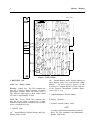
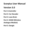
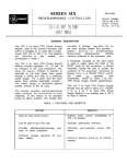
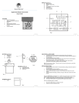
Figure 1. USER ITEMS
I. BATTERY Light
Steady On:
Battery Normal
Flashing: Battery Low: The CPU continues running. No. 2 (advisory) alarm is activated. To protect
the memory contents, replace the battery before it
fails. When the light begins to flash, battery failure
will occur in approximately 30 days.
Steady Off:
Battery Failed: CPU continues running, but will not restart if stopped. No. 2 alarm
remains activated. Memory contents will be lost when
power is switched off or lost.
2. PARITY Light
o n : Internal Memory, Register Memory and Logic
Memory Parity are OK.
off: Internal Memory and/or Register Memory or
Logic Memory parity error occurred when reading
memory.
An error message appears on the
Workmaster Computer display or in the work area
of the Program Development Terminal display.
Causes CPU to stop.
3. Lithium-Manganese Dioxide Battery
4. Battery Connectors
5, External Auxiliary Battery Select
NOTE
For battery replacement information, consult the
Series Six Plus Installation and Maintenance
Manual, GEK-96602.
Memory Modules
3
GFK-0146
INSTALLATION
The Combined Memory module (LOGIC MEMORY)
is installed in the card slot to the immediate left of the
Arithmetic Control module in the CPU rack. Follow
these steps for installation:
1.
Connect 2-pin l ithum battery connector to
either male jack beneath battery if not using
auxiliary battery inputs on power supply terminal strip.
2.
If auxiliary battery is used, the battery does
not have to be on the board.
3.
Use extraction/insertion tool furnished with
CPU to insert (or remove) module into rack.
4.
Secure faceplate to rack using screws at top
and bottom.
5.
Clear parity errors detected at initial
power-up of the CPU. Refer to Chapter 11,
of the Logicmaster 6 User’s Manual,
GEK-25379.
Do not allow the bottom of this circuit board to
come into contact with a conductive (metal) surface when the board cover has been removed.
Failure to observe this caution could result in
the discharge of the non-rechargeable lithium
battery and the loss of the memory contents.
Relatively small amounts of excess charge can
cause very intense electrostatic fields in
metal-oxide-semiconductor (MOS) devices,
damaging their gate structure. Avoid handling
this circuit board in a manner which might
cause electrostatic charges. Failure to observe
this caution could result in the destruction of the
CMOS-RAM devices in this module.
WARNING
I
DO
I
I
not discard the lithium-manganese dioxide battery in either fire or water. Do not
place a short circuit between the contacts at
the ends of the battery. Do not attempt to
recharge the battery. Failure to observe any
of these warnings map cause the battery to
burst or burn or release hazardous materials.
Memory Modules
4
GFK-0146
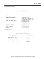
Table 2. SPECIFICATIONS
Dimensions:
Circuit Board:
Faceplate:
Power Requirements:
(Supplied by CPU power supply)
*Register Memory Capacity:
*Logic (user) Memory Capacity:
Operating
Temperature:
Storage Temperature:
Humidity:
8.15 x 11.0 (inches), 208 x 280 (mm)
12.46 x 1.175 (inches), 317 x 30 (mm)
5 V dc, 1.5 A (max), -12 V dc, 10 mA (max)
1K l6-Bit words; 5K version
8K 16-Bit words; 12K, 16K or 24K versions
16K 16-Bit words; 48K and 80K versions
4,096 (4K) 16-Bit words
8,192 (8K) 16-Bit words
16,384 (16K) 16-Bit words
32,768 (32K) 16-Bit words
65,536 (64K) l6-Bit words
O to 60° C (32 to 140F)
(outside of rack)
-20 to 70C (-4 TO 158F’)
5%-95% {non-condensing)
*with battery back-up
Table 3. ORDERING INFORMATION
DESCRIPTION
4K/lK Logic/Register Memory
4K/8K Logic/Register Memory
8K/8K
Logic/Register
Memory
16K/16K Logic//Register Memory
32K./16K Logic/Register Memory
64K/16K
Logic/Register Memory
CATALOG NUMBER
IC600LX 5K
IC600LX612K
IC600LX616K
IC600LX624K
IC600LX648K
IC600LX68OK
For further information, contact your local GE Fanuc
sales office.
GE Fanuc Automation North America, Inc., Charlottesville, Virginia