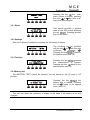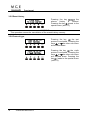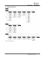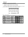
1
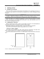
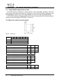
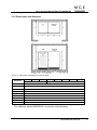
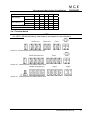
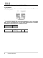
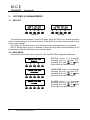
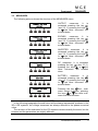
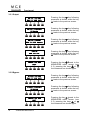
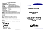
www.mgeups.com
COMET 3000 3:1
COMET 3000 3:3
15-80kVA
Installation and user
manual
English
UPS OPERATING MANUAL
Index of sections
Code
1 – UPS GENERAL DESCRIPTION AND INSTALLATION
34005002EN
2 – FRONT PANEL
34005003EN
3 – START-UP, SHUT-DOWN AND MANUAL BYPASS
34005004EN
4 – REMOTE CONNECTION OF THE UPS
34005005EN
34005001EN REVISION C
1
Ups general description & installation
UPS GENERAL DESCRIPTION AND INSTALLATION
Index
1.
INTRODUCTION.................................................................................. 3
1.1
ENVIRONMENT................................................................................................3
1.1.1
ISO 14001 certification.............................................................................3
1.1.2
UPS treatment at the end of service life.................................................3
1.1.3
Packing .....................................................................................................3
1.1.4
Lead battery..............................................................................................3
1.2
SAFETY RULES ...............................................................................................3
1.2.1
Safety of persons .....................................................................................3
1.2.2
Product safety ..........................................................................................4
1.2.3
Special precautions .................................................................................4
2.
UPS GENERAL DESCRIPTION......................................................... 5
2.1
TYPOLOGY ......................................................................................................5
2.2
SYSTEM DESCRIPTION ..................................................................................6
2.2.1
Rectifier.....................................................................................................6
2.2.2
Inverter ......................................................................................................6
2.2.3
Battery and battery charger ....................................................................6
2.2.4
Static bypass ............................................................................................6
2.2.5
Manual bypass .........................................................................................6
2.2.6
Front panel................................................................................................6
2.3
OPERATING STATUS......................................................................................7
2.3.1
Normal operation .....................................................................................7
2.3.2
Load supplied by bypass due to inverter fault ......................................7
2.3.3
Rectifier failure or mains failure .............................................................8
2.3.4
Manual bypass .........................................................................................8
3.
INSTALLATION.................................................................................. 9
3.1
RECEIPT OF THE UPS ....................................................................................9
3.2
HANDLING OF THE UPS.................................................................................9
34005002EN REVISION D
1
Ups general description & installation
3.3
POSITIONING AND INSTALLATION ............................................................ 10
3.3.1
Base plan, static load and weights ...................................................... 10
3.3.2
Dimensions and distances ................................................................... 11
3.4
ELECTRICAL CONNECTION........................................................................ 12
3.4.1
Terminal board ...................................................................................... 13
3.5
BATTERY CONNECTION AND POSITIONING ............................................ 14
3.6
EXTERNAL BATTERY .................................................................................. 15
3.6.1
Dimensions and weights ...................................................................... 16
3.6.2
Connections........................................................................................... 18
Index of pictures
Picture 1 - Block diagram ............................................................................................................................. 5
Picture 2 - Normal operation......................................................................................................................... 7
Picture 3 - Load supplied by bypass............................................................................................................. 7
Picture 4 - Rectifier failure or mains failure................................................................................................... 8
Picture 5 - Manual bypass ............................................................................................................................ 8
Picture 6 - Handling of UPS from 15kVA to 80kVA ...................................................................................... 9
Picture 7 - Base plan .................................................................................................................................. 10
Picture 8 - Dimensions and distances from the walls................................................................................. 11
Picture 9 - Terminal board UPS 15kVA÷30kVA 1Ph.................................................................................. 13
Picture 10 - Terminal board UPS 20kVA÷30kVA 3Ph................................................................................ 13
Picture 11 - Terminal board UPS 40kVA÷80kVA 3Ph................................................................................ 13
Picture 12 - Battery connection UPS 15kVA÷30kVA.................................................................................. 15
Picture 13 - Base plan of the external battery cabinet................................................................................ 16
Picture 14 - Dimensions of the external battery cabinet............................................................................. 16
Picture 15 - Battery cabinets connections .................................................................................................. 18
2
34005002EN REVISION D
Ups general description & installation
1.
INTRODUCTION
1.1 ENVIRONMENT
1.1.1 ISO 14001 certification
The product was manufactured in a factory certified ISO 14001 respecting ecodesign rules.
1.1.2 UPS treatment at the end of service life
MGE UPS SYSTEMS undertakes to recycle, by certified companies and in
compliance with all applicable regulations, all UPS products recovered at the end of
their service life (contact your branch office).
1.1.3 Packing
UPS packing materials must be recycled in compliance with all applicable
regulations.
1.1.4 Lead battery
This product contains lead-acid batteries. Lead is a dangerous substance for the
environment if it is not correctly recycled by specialised companies.
1.2 SAFETY RULES
1.2.1 Safety of persons
The UPS must be installed in a room with restricted access (qualified personnel only,
according to standard EN50091-1-2).
A UPS has its own internal power source (the battery). Consequently, the power
outlets may be energised even if the UPS is disconnected from the AC-power source.
CAUTION
If primary powers isolators are installed in other area from UPS area.
You must stick the following warning label on them.
“ISOLATE UNINTERRUPTIBLE POWER SUPPLY (UPS) BEFORE WORKING ON
THIS CIRCUIT”
Dangerous voltage levels are present within the UPS. It should be opened
exclusively by qualified service personnel.
Warning, after the UPS shut-down, a dangerous voltage will be present on the
battery selector BCB.
The UPS must be properly earthed.
The battery supplied with the UPS contains small amounts of toxic materials.
To avoid accidents, the directives listed below must be observed.
w Never operate the UPS if the ambient temperature and relative humidity are
higher than the levels specified in the documentation.
34005002EN REVISION D
3
Ups general description & installation
Never burn the battery (risk of explosion).
w Do not attempt to open the battery (the electrolyte is dangerous for the eyes
and skin).
w Comply with all applicable regulations for the disposal of the battery.
1.2.2 Product safety
A protection circuit breaker must be installed upstream and be easily accessible.
Never install the UPS near liquids or in an excessively damp environment.
Never let a liquid or foreign body penetrate inside the UPS.
Never block the ventilation grates of the UPS.
Never expose the UPS to direct sunlight or a source of heat.
1.2.3 Special precautions
The UPS connection instructions contained in this manual must be followed in the
indicated order.
w Check that the indications on the rating plate correspond to your AC-power system
and to the actual electrical consumption of all the equipment to be connected to the
UPS.
w If the UPS must be stored prior to installation, storage must be in a dry place.
w The admissible storage temperature range is -10° C to +45° C.
w If the UPS remains de-energised for a long period, we recommend that you
energise the UPS for a period of 24 hours, at least once every month. This charges the
battery, thus avoiding possible irreversible damage.
w The UPS is designed for normal climatic and environmental operating conditions as
defined in the "appendices" chapter: altitude, ambient operating temperature, relative
humidity and ambient transport and storage conditions.
w Using the UPS within the given limits guarantees its operation, but may affect the
service life of certain components, particularly that of the battery and its autonomy. The
maximum storage time of the UPS is limited due to the need to recharge its integrated
battery.
w Unusual operating conditions may justify special design or protection measures:
harmful smoke, dust, abrasive dust,
humidity, vapor, salt air, bad weather or dripping,
explosive dust and gas mixture,
extreme temperature variations,
bad ventilation,
conductive or radiant heat from other sources,
strong electromagnetic fields,
radioactive levels higher than those of the natural environment,
fungus, insects, vermin, etc.,
battery operating conditions.
w
The UPS must always be installed in compliance with:
-
4
the requirements of HD 384.4.42 S1/A2 - Chapter 42:
thermal effects.
34005002EN REVISION D
Protection from
Ups general description & installation
-
standard IEC 60364-4-482 - Chapter 482: Fire protection.
The manufacturer declines all responsibility for damages to people or
equipment deriving from non-fulfilment of the above.
2.
UPS GENERAL DESCRIPTION
2.1 TYPOLOGY
All UPS covered by this manual are on-line, double conversion; the inverter supplies
always energy to the load, whether mains is available or not (according to the battery
autonomy time).
WARNING
The UPS output is energized even during mains failure, therefore in compliance with
the prescriptions of EN 50091-1, the installer will have to identify the line or the plugs
supplied by the UPS making the User aware of this fact.
This configuration guarantees the best service to the User, as it supplies clean
continuously regulated power and guarantees the voltage and frequency will be
stabilised at nominal value independently from mains status. Thanks to the double
conversion, it makes the load completely immune from micro-interruptions due to
excessive mains variation, and prevents damage to the critical load (Computer Instrumentation - Scientific equipment etc.).
Picture 1 - Block diagram
34005002EN REVISION D
5
Ups general description & installation
2.2 SYSTEM DESCRIPTION
2.2.1 Rectifier
It converts the three phase voltage of the mains into continuous DC voltage.
It uses a three phase 6 pulses fully-controlled thyristors bridge.
It’s designed to supply the inverter at full load and the battery at the maximum
recharge current. The system offers very low ripple content during the charging cycle.
2.2.2 Inverter
It converts the continuous voltage coming from the rectifier or from the battery into
alternating voltage stabilized in amplitude and frequency.
The inverter uses IGBT technology with a frequency commutation of approximately
10 KHz.
The control electronics is completely digital and uses a 16 Bit μP, that, thanks to its
processing capability, generates an excellent output sine-wave, which has a very low
distortion even in presence of loads having high crest factor currents.
2.2.3 Battery and battery charger
On the 15-30kVA 3:1 and 20-30kVA 3:3 UPS battery can be located inside the UPS
for autonomy from 5 up to 15 minutes depending on the UPS power (see tables page
10); on the other hand, battery is placed on external cabinet.
Warning: only the 15-30kVA 3:1 and 20-30kVA 3:3 UPS can have internal batteries.
The UPS with bigger sizes have to be placed on external battery cabinets.
The battery charger control logic is completely integrated inside the total-controlled
rectifier control board; the battery is charged, according to the DIN 41773 Standard,
every time it has been partially or completely discharged and it is kept floating, even
when it’s charged, to compensate for any autodischarge.
2.2.4 Static bypass
It’s designed to transfer the load between INVERTER and MAINS, and vice-versa,
without break, and uses SCR’s as power commutation elements.
2.2.5 Manual bypass
It‘s used to by-pass the UPS, supplying the load directly to the mains in case of
maintenance or serious failure.
WARNING
The sequence of bypass switching must be carried out with respect to the procedure
indicated on the UPS and in the chapter “Start-up, shut-down and manual bypass”. The
manufacturer cannot accept responsibility for damages arising from incorrect operation.
2.2.6 Front panel
The front panel of the UPS, consisting of a double row alphanumeric displays plus 5
function keys, allows the complete monitoring of the UPS status.
The mimic diagram helps to understand the operating status of the UPS.
For more information see the chapter “FRONT PANEL”.
6
34005002EN REVISION D
Ups general description & installation
2.3 OPERATING STATUS
The following paragraphs show all the possible operating status of the UPS.
2.3.1 Normal operation
The inverter is supplied by the rectifier; the load, through the static switch, is supplied
directly by the inverter output.
Picture 2 - Normal operation
2.3.2 Load supplied by bypass due to inverter fault
The load is transferred to bypass through the static switch; the transfer is carried out
without interruption.
Picture 3 - Load supplied by bypass
34005002EN REVISION D
7
Ups general description & installation
2.3.3 Rectifier failure or mains failure
The inverter is supplied by the battery for the required autonomy time; the load,
through the static switch, is supplied directly by the inverter output.
Picture 4 - Rectifier failure or mains failure
2.3.4 Manual bypass
The load is supplied by the mains through the manual bypass; the operator can work
in safety on the UPS to carry out maintenance or repairing operations.
Picture 5 - Manual bypass
8
34005002EN REVISION D
Ups general description & installation
3.
INSTALLATION
3.1 RECEIPT OF THE UPS
When the UPS is received, please attend immediately to its unpacking and carry-out
an accurate visual check to be sure that the equipment has not been damaged during
transport.
IMPORTANT
In case of objections relating to damage incurred during transport these must be
immediately notified to the transportation company after receipt of the equipment.
When the UPS is not installed immediately it must be stored carefully in vertical
position, as indicated on the packing and conserved in a dry and sheltered room in its
box so that it is protected from dust.
3.2 HANDLING OF THE UPS
Before positioning the UPS, in order to avoid risks of turnover, it’s recommended to
move the system on the wood pallet on which the UPS is fixed.
Before the positioning in the final location, remove the UPS from the pallet.
The UPS can be lifted and handled using a pallet truck or a forklift.
- UPS from 15kVA to 80kVA
The UPS can be handled only after having taken-off (manually), the lower front
panel, so that a pallet truck or a forklift can be inserted (see picture 6).
The UPS technical data are shown on a label fixed on the internal side of the front
door.
Picture 6 - Handling of UPS from 15kVA to 80kVA
34005002EN REVISION D
9
Ups general description & installation
3.3 POSITIONING AND INSTALLATION
The UPS must be installed in a clean and dry room, preferably not dusty. The User
must ensure that there is enough air exchange in the room so that the equipment can
be adequately cooled; if this is not guaranteed, the room must be adequately aired.
If the UPS contains the batteries internally the air exchange with the external ambient
will have to be according to EN 50091-1, annex N.
3.3.1 Base plan, static load and weights
Picture 7 - Base plan
UPS
(kVA)
15
20
30
40
60
80
1Ph & 3Ph
L1 – mm
650
P1 – mm
820
L2 – mm
25
1Ph UPS (kVA)
15
20
30
Weight w/o battery – kg
293
308
320
Weight with battery (5 minutes autonomy) – kg
422
437
487
Weight with battery (10 minutes autonomy) – kg
460
475
621
Weight with battery (15 minutes autonomy) – kg
490
505
20
30
Weight w/o battery – kg
323
339
Weight with battery (5 minutes autonomy) – kg
452
506
Weight with battery (10 minutes autonomy) – kg
490
640
Weight with battery (15 minutes autonomy) – kg
520
3Ph UPS (kVA)
3Ph UPS (kVA)
Weight w/o battery – kg
10
34005002EN REVISION D
40
60
80
385
439
456
Ups general description & installation
3.3.2 Dimensions and distances
Picture 8 - Dimensions and distances from the walls
UPS (kVA)
L – mm
15
20
30
20
30
1Ph
875
1345
ADD. CABINET
L1 – mm
80
690
H – mm
Y (min.) – mm
60
3Ph
P – mm
X (min.) – mm
40
50
500
WWCBV011
815
P1 – mm
820
H1 – mm
1345
The additional cabinet WWCBV011 is used for external battery.
34005002EN REVISION D
11
Ups general description & installation
3.4 ELECTRICAL CONNECTION
The electrical connection is part of the work which is normally provided by the
supplier that carries out the electrical installation and not by the UPS manufacturer. For
this reason, the following recommendations are only an indication, as the UPS
manufacturer is not responsible for the electrical installation.
In any case we recommend to carry-out the installation and the electrical connections
of the input and output in compliance with the local standards.
During the electrical installation take particular care to check the phase rotation with
a suitable instrument.
- UPS from 15kVA to 30 kVA
The terminals are positioned at the front of the UPS and they can be accessed by
opening the front door.
- UPS from 40kVA to 80 kVA
The terminal boards are positioned at the front of the UPS, under the breakers. To
access the terminals remove the protection, extracting the fixing bolts.
WARNING
The connection to the mains must be carried out with protection fuses or circuit
breakers between the mains and the UPS.
The use of residual current devices in the line supplying the UPS is
unadvisable. The leakage current due to the RFI filters is rather high and it can
cause spurious tripping of the protection device.
According to the EN50091-1 standard, in order to take into account the UPS’ leakage
current, residual current devices having adjustable threshold can be used (see tables).
1Ph UPS (kVA)
15
20
30
Leakage current L1-L2-L3-N (mA)
30
30
30
Leakage current L1-L2-L3 (mA)
200
200
200
20
30
40
60
80
Leakage current L1-L2-L3-N (mA)
30
30
40
40
80
Leakage current L1-L2-L3 (mA)
20
20
20
20
30
3Ph UPS (kVA)
The connection cables section is shown in the following tables.
1Ph UPS (kVA)
Input fuses (A)
15
20
30
Rectifier
3x32
3x50
3x80
Bypass
1x100 1x150 1x200
Rectifier
3x6
3x10
3x25
Bypass
2x25
2x35
2x70
Output cables
(mm2)
2x25
2x35
2x70
Battery cables
(mm2)
2x10
2x16
2x25
Input cables (mm2)
12
34005002EN REVISION D
Ups general description & installation
3Ph UPS (kVA)
Input fuses (A)
Input cables (mm2)
Rectifier
20
30
40
60
80
3x50
3x80
3x100 3x150 3x150
3x150 3x200 3x200
Bypass
-
-
Rectifier
4x10
4x25
3x35
3x50
3x70
Bypass
-
-
4x35
4x50
4x70
(mm2)
4x10
4x25
4x35
4x50
4x70
Battery cables (mm2)
2x16
2x25
2x50
2x50
2x70
Output cables
3.4.1 Terminal board
NOTE
For UPS ≤ 30kVA the battery fuse holder is connected to internal battery.
Picture 9 - Terminal board UPS 15kVA÷30kVA 1Ph
Picture 10 - Terminal board UPS 20kVA÷30kVA 3Ph
Picture 11 - Terminal board UPS 40kVA÷80kVA 3Ph
34005002EN REVISION D
13
Ups general description & installation
3.5 BATTERY CONNECTION AND POSITIONING
IMPORTANT
For battery installation please respect the EN62040-1-2 prescriptions, paragraph
4.9.20, and at the same time all the national rules or specifications which can be applied
to the premises or building.
To obtain the battery life indicated by the battery manufacturer, the operating
temperature must remain between 0 and 25 °C. However, although the battery can
operate up to 40 °C , there will be a significant reduction of the battery life.
To avoid the formation of any kind of potentially explosive hydrogen and oxygen
mixture, suitable ventilation must be provided where the battery are installed (see
EN62040-1-2 annex N).
For the materials installed in France, we have to apply the rules according to NFC
15-100 article 554.2: the volume of the renewed air has to be at least 0,005 NI m3 per
hour, where N is the number of the elements inside the battery and I is maximun current
of the rectifier.
The batteries can be internal or external, however, it is recommended to install them
when the UPS is capable of charging them. Please remember that, if the battery is not
charged for periods over 2-3 months they can be subject to irreparable damage.
In order to avoid any damage during the transport battery is delivered with some
connection cables disconnected (in order to have a battery voltage for each shelve less
than 120V) and with protecteve carboard.
At the time of the installation you will have to provide to remove the protecteve
carboard (as indicated on label 3400433900) and to reconnect the cables (as
indicated on label 5102881200).
IMPORTANT
Only the UPS’s 15-20KVA and 30kVA (up to 10’ autonomy) 1Ph and 3Ph, have
internal batteries. The bigger sizes must be connected with external battery cabinets.
14
34005002EN REVISION D
Ups general description & installation
Picture 12 - Battery connection UPS 15kVA÷30kVA
3.6 EXTERNAL BATTERY
The external battery is used to increase the UPS autonomy time during mains failure.
It’s always provided for UPS’s having ratings 30KVA 15’ auton. and UPS > 40kVA
IMPORTANT
With an external battery, the internal battery isn’t necessary.
The battery circuit breaker is installed inside the external battery cabinet, so it’s not
provided in the UPS.
Concerning the installation of the external battery cabinet, refer to the details given in
paragraph 3.5.
34005002EN REVISION D
15
Ups general description & installation
3.6.1 Dimensions and weights
The dimensions and weights of the external battery cabinet are indicates here under.
Picture 13 - Base plan of the external battery cabinet
Picture 14 - Dimensions of the external battery cabinet
16
34005002EN REVISION D
Ups general description & installation
CABINET
AS410
L – mm
815
P – mm
820
H – mm
1345
L1 – mm
775
P1 – mm
775
L2 – mm
25
TYPE CABINET
AS410
(Without battery)
AS410_6418
(64 x 18Ah)
AS410_3224
(32 x 24 Ah)
AS410_3238
(32 x 38 Ah)
AS410_6424
(64 x 24 Ah)
AS410_3264
(32 x 64 Ah)
AS410_6438
(64 x 38 Ah)
WEIGHT
(KG)
161
555
462
641
763
929
1089
34005002EN REVISION D
17
Ups general description & installation
3.6.2 Connections
The following picture shows the electrical connection between the UPS and the
external battery cabinet.
Picture 15 - Battery cabinets connections
The connection cables are two power cables, with section of 50mm2 (see following
table) and with length ranging from 2 to 50m. Longer cables are subject to excessive
voltage drop, so their section must be increased accordingly.
1Ph UPS (kVA)
Battery cables (mm2)
3Ph UPS (kVA)
Battery cables (mm2)
18
30
15’ Autonomy
2x50
30
15’ Autonomy
2x50
34005002EN REVISION D
40
60
80
2x50
2x50
2x50
Front panel
FRONT PANEL
Index
1.
INTRODUCTION................................................................................. 3
2.
DESCRIPTION.................................................................................... 4
2.1
MIMIC DESCRIPTION ......................................................................................4
2.2
ALARMS AND OPERATING STATUS.............................................................5
3.
LCD DISPLAY MANAGEMENT ......................................................... 8
3.1
DEFAULT .........................................................................................................8
3.2
MAIN MENU .....................................................................................................8
3.3
MEASURES ......................................................................................................9
3.3.1
Output .....................................................................................................10
3.3.2
Bypass ....................................................................................................10
3.3.3
Inverter ....................................................................................................11
3.3.4
AC/DC......................................................................................................11
3.3.5
Battery.....................................................................................................12
3.4
ALARMS.........................................................................................................13
3.4.1
UPS Status..............................................................................................13
3.4.2
History.....................................................................................................14
3.4.3
List of alarms and status .......................................................................15
3.5
SPECIAL.........................................................................................................16
3.5.1
Reset .......................................................................................................17
3.5.2
Settings ...................................................................................................17
3.5.3
Test Ups ..................................................................................................17
3.5.4
Battery test .............................................................................................17
3.5.5
Reset history ..........................................................................................18
3.5.6
Protocol type ..........................................................................................18
3.6
MENU STRUCTURE.......................................................................................19
34005003EN REVISION A
1
Front panel
Index of pictures
Picture 1 - Front panel .................................................................................................................................. 3
Picture 2 - Menu structure .......................................................................................................................... 19
2
34005003EN REVISION A
Front panel
1.
INTRODUCTION
The front panel of the UPS, consisting of a double row alphanumeric display plus 5
function keys, allows the complete monitoring of the UPS status.
The mimic flow helps to understand the operating status of the UPS.
Picture 1 - Front panel
34005003EN REVISION A
3
Front panel
2.
DESCRIPTION
2.1 MIMIC DESCRIPTION
Picture1 shows the mimic present on the display, with the names of the circuit
breakers/isolator switches of the UPS. Also the led's and blocks that comprise the UPS
are clearly identified.
4
LED 1
⇒
Lit-up green = Mains present at the rectifier input.
Otherwise off.
LED 2
⇒
Lit-up green = Emergency line present and phase
sequence correct.
Otherwise off.
LED 3
⇒
Lit-up green = Rectifier feeding correctly.
Lit-up red = Rectifier output voltage out of tolerance.
LED 4
⇒
Lit-up green = Battery OK.
Green flashing = Battery discharging or battery in test.
Orange flashing = BCB open.
Lit-up red = Battery test aborted.
LED 5
⇒
Lit-up green = Inverter static switch closed.
Otherwise off.
LED 6
⇒
Lit-up orange = Emergency line static switch closed.
Otherwise off.
LED 7
⇒
Lit-up green = Voltage present on the load.
Lit-up orange = OCB circuit breaker open.
LED 8
⇒
Lit-up orange = Manual by-pass closed. Otherwise off.
34005003EN REVISION A
Front panel
2.2 ALARMS AND OPERATING STATUS
The alphanumeric display offers a complete diagnostic of the system by showing 25
alarms and 6 operating status descriptions.
Each alarm is associated to a code that allows it to be stored in the events history.
A1 MAINS FAULT
= Rectifier input mains failure
Possible causes: 1) Central system black-out (mains failure)
2) Distribution problems upstream of the UPS
3) RCB open
A2 CHARGER FAULT
= Battery charger failure
A3 RECT FUSE
= One or more rectifier fuses are blown
A4 THER IMAGE
= Load transferred to mains due to overload. After 30’
the load is transferred back to inverter
A5 AC/DC FAULT
= Rectifier output voltage out of tolerance
Possible causes: 1)
2)
3)
4)
Mains input voltage too high/low
Distribution problems upstream of the UPS
RCB open
Rectifier bridge failure
A6 INPUT WR SEQ
= Input phase rotation not correct
A7 BCB OPEN
= Battery circuit breaker open
A8 BATT DISCH
= The battery is discharging
Possible causes: 1) Rectifier input mains failure (alarm A1 present)
2) Rectifier failure
A9 BATT AUT END
= Battery autonomy (calculated) has expired
A10 BATT FAULT
= Battery test failed
Possible causes: 1) The test has been carried out with the battery not
perfectly charged
2) One or more battery cells are damaged
A11 BATT IN TEST
= Battery test in progress
A12 PLL FAULT
= Problems with the digital synchronisation system
Possible causes: 1) Emergency
mains
excessively
disturbed
34005003EN REVISION A
or
5
Front panel
intermittent
2) Mains variation speed not acceptable for the UPS (for
load protection reasons)
A13 INV OUT TOL
= Inverter output voltage out of tolerance
Possible causes: 1) Intervention of the inverter current limitation for
excessive load (more than 200%)
2) Inverter failure
A14 OVERLOAD
= Inverter overload (load exceeding 100%). The
thermal image protection is started
A15 BYP FAULT
= Emergency mains not available
Possible causes: 1)
2)
3)
4)
A16 BYP FEED LOAD
Emergency mains failure
Distribution problems upstream of the UPS
SBCB open
Wrong input phase rotation
= Load fed by bypass
Possible causes: 1) Inverter overload
2) Thermal image intervention
3) Forced commutation due to the bypass switch
operation
4) Inverter failure
A17 RETR BLOCK
= Re-transfer between bypass and inverter blocked,
load on bypass
Possible causes: 1) Excessive repeated overloads on inverter
It is possible, after having verified that the load is correct, to reset the UPS, and
switch back the load to the inverter (see menu SPECIAL).
A18 MBYP CLOSE
= Manual bypass breaker closed (the inverter is
shutdown)
A19 OCB OPEN
= UPS output breaker open
A20 FANS FAILURE
= Optional
A21 HIGH TEMP
= High temperature on the inverter and/or rectifier
bridge
Possible causes: 1) Excessive load
2) Failure or malfunctioning of the cooling system
6
34005003EN REVISION A
Front panel
3) Wrong positioning of the UPS (distance from walls,
altitude)
A22 BYP SWITCH
= Closure of the commutation switch which forces the
load to bypass (maintenance)
A23 EPO BUS
= Intervention of the emergency power off switch
according to the EN50091-1
A24 CURR STOP
= Inverter bridge stop for max current
Possible causes: 1) Repeated short circuits at the UPS output
2) Inverter bridge malfunctioning
This state can be reset by means of a push-button on the μP board.
A25 SHORT CIRC
= Intervention of the short circuit protection (current
exceeding 200%)
Possible causes: 1) Problems on the load
2) Distribution problems downstream of the UPS
34005003EN REVISION A
7
Front panel
3.
LCD DISPLAY MANAGEMENT
3.1 DEFAULT
<NAME> xxx KVA
Vout = XXX Volt
<NAME> xxx KVA
XXX YYY ZZZ Volt
1Ph UPS
3Ph UPS
The default screen appears on the LCD panel when the UPS is in normal operation
(with no alarm present); it shows the name of the UPS the nominal power and the value
of the output voltage.
Pressing a key the main menu, with all the functions and parameters, is accessed
After 5’ during which no key is pushed, if there isn’t any alarm and the battery is not
in discharge mode the Default screen is shown again.
3.2 MAIN MENU
The screen of the main menu, equal for 1Ph and 3Ph UPS’s, appears as follows.
8
<NAME> xxx KVA
SPECIAL
SPECIAL menu. It is accessed
pressing the key
(see 3.5),
or
the
pressing the keys
other menu are scrolled down.
<NAME> xxx KVA
MEASURES
MEASURES menu. It is accessed
pressing the key
(see 3.3),
or
the
pressing the keys
other menu are scrolled down.
<NAME> xxx KVA
ALARMS
ALARMS menu. It is accessed
pressing the key
(see 3.4),
or
the
pressing the keys
other menu are scrolled down.
34005003EN REVISION A
Front panel
3.3 MEASURES
The following pictures shows the structure of the MEASURES menu.
<NAME> xxx KVA
OUTPUT
OUTPUT
measures.
It
is
accessed pressing the key
(see 3.3.1), pressing the keys
or
the other sub-menu are
scrolled down.
<NAME> xxx KVA
BYPASS
BYPASS
measures.
It
is
accessed pressing the key
(see 3.3.1), pressing the keys
or
the other sub-menu are
scrolled down.
<NAME> xxx KVA
INVERTER
INVERTER measures. It is
accessed pressing the key
(see 3.3.1), pressing the keys
or
the other sub-menu are
scrolled down.
<NAME> xxx KVA
AC/DC
DC measures. It is accessed
(see 3.3.1),
pressing the key
pressing the keys
or
the
other sub-menu are scrolled
down.
<NAME> xxx KVA
BATTERY
BATTERY
measures.
It
is
accessed pressing the key
(see 3.3.1), pressing the keys
or
the other sub-menu are
scrolled down.
<NAME> xxx KVA
EXIT
Pressing the key
the main
menu screen is shown, pressing
the keys
or
the other submenu are scrolled down.
NOTE
In the following paragraphs the sub-menu will be always represented as shown in the
3Ph UPS systems; the voltage measures are always referred to the phase-to-neutral
value.
The structure of the sub-menu for the 1Ph systems remains exactly the same, but the
screens and the parameters are slightly different.
34005003EN REVISION A
9
Front panel
3.3.1 Output
OUTPUT VOLTAGE
XXX YYY ZZZ Volt
Pressing the key
the following
parameter is shown, while the key
leads to the previous screen.
OUTPUT FREQUENCY
XX Hertz
Pressing the key
the following
parameter is shown, while the key
leads to the previous screen.
OUTPUT CURRENT
XXX YYY ZZZ Ampere
Pressing the key
the following
parameter is shown, while the key
leads to the previous screen.
LOAD %
XXX YYY ZZZ
Pressing the key
the following
parameter is shown, while the key
leads to the previous screen.
<NAME> xxx KVA
EXIT
Pressing the key
leads to the
MEASURES menu screen (see
3.3), pressing the keys
or
the measures are shown again.
BYPASS VOLTAGE
XXX YYY ZZZ Volt
Pressing the key
the following
parameter is shown, while the key
leads to the previous screen.
BYPASS FREQUENCY
XX Hertz
Pressing the key
the following
parameter is shown, while the key
leads to the previous screen.
<NAME> xxx KVA
EXIT
Pressing the key
leads to the
MEASURES menu screen (see
3.3), pressing the keys
or
the measures are shown again.
3.3.2 Bypass
10
34005003EN REVISION A
Front panel
3.3.3 Inverter
INVERTER VOLTAGE
XXX YYY ZZZ Volt
Pressing the key
the following
parameter is shown, while the key
leads to the previous screen.
INVERTER FREQUENCY
XX Hertz
Pressing the key
the following
parameter is shown, while the key
leads to the previous screen.
<NAME> xxx KVA
EXIT
Pressing the key
leads to the
MEASURES menu screen (see
3.3), pressing the keys
or
the measures are shown again.
3.3.4 AC/DC
This menu is active only when the battery is not discharging. If the battery is in
discharge mode the menu BATTERY is automatically shown.
AC/DC VOLTAGE
XXX Vdc
Pressing the key
the following
parameter is shown, while the key
leads to the previous screen.
<NAME> xxx KVA
EXIT
Pressing the key
leads to the
MEASURES menu screen (see
3.3), pressing the keys
or
the measures are shown again.
34005003EN REVISION A
11
Front panel
3.3.5 Battery
12
BATTERY VOLTAGE
XXX Vdc
Pressing the key
the following
parameter is shown, while the key
leads to the previous screen.
BATTERY TYPE
XXX Ah
Pressing the key
the following
parameter is shown, while the key
leads to the previous screen.
BATTERY CURRENT
XXX Ampere
Pressing the key
the following
parameter is shown, while the key
leads to the previous screen.
AUTONOMY
XXX min
Pressing the key
the following
parameter is shown, while the key
leads to the previous screen.
AUTONOMY %
XXX %
Pressing the key
the following
parameter is shown, while the key
leads to the previous screen.
<NAME> xxx KVA
EXIT
Pressing the key
leads to the
MEASURES menu screen (see
or
the
3.3), pressing the key
measures are shown again.
34005003EN REVISION A
Front panel
3.4 ALARMS
This menu, when selected, shows the status of the equipment and the current alarms
are shown (see list below).
Each time an alarm occurs, the display goes to this menu to indicate the alarms
present; the audible alarm can be silenced pressing the key . The exit is disabled if
the alarm is not silenced.
The following pictures shows the structure of the ALARMS menu.
<NAME> xxx KVA
UPS STATUS
Alarms and status of the UPS. It
is accessed pressing the key
(see 3.4.1), pressing the keys
or
the other sub-menu are
scrolled down.
<NAME> xxx KVA
HISTORY
Alarms history. It is accessed
pressing the key
(see 3.4.2),
pressing the keys
or
the
other sub-menu are scrolled
down.
<NAME> xxx KVA
EXIT
Pressing the key
the main
menu screen is shown, pressing
or
the other subthe keys
menu are scrolled down.
3.4.1 UPS Status
UPS STATUS
1st alarm/status
Pressing the key
the status
and/or the alarm of the UPS are
shown, while the key
leads to
the previous screen.
UPS STATUS
Last alarm/status
The key
leads to the previous
alarm/status, while pressing the
key
the EXIT screen is
accessed.
UPS STATUS
EXIT
Pressing the key
leads to the
ALARMS menu screen (see 3.4),
or
the
pressing the key
alarms and/or status are shown
again.
34005003EN REVISION A
13
Front panel
3.4.2 History
RET TO EXIT HISTORY
1st alarm/status
Pressing the key
the following
alarm is shown; pressing the key
exit the history, leading to the
ALARMS menu screen (see 3.4).
RET TO EXIT HISTORY
2nd alarm/status
Pressing the key
the following
alarm is shown; pressing the key
exit the history, leading to the
ALARMS menu screen (see 3.4).
RET TO EXIT HISTORY
3rd alarm/status
Pressing the key
the following
alarm is shown; pressing the key
exit the history, leading to the
ALARMS menu screen (see 3.4).
RET TO EXIT HISTORY
Last alarm/status
Pressing the key
the first alarm
is shown again; pressing the key
exit the history, leading to the
ALARMS menu screen (see 3.4).
The first alarm shown is the most recent in order of time; a new alarm makes all the
alarms shift one position, clearing the oldest event.
For each event is shown the alarm code, the date and time; an asterisk next to the
code indicates that the alarm has cleared at the date and time indicated. The following
example shows two possible screens.
14
RET TO EXIT HISTORY
A1
251201
1848
Alarm A1 (MAINS FAULT) on
25/12/01 at 18:48.
RET TO EXIT HISTORY
A1 * 251201
2012
Reset of alarm A1 (MAINS
FAULT) on 25/12/01 at 20:12.
34005003EN REVISION A
Front panel
3.4.3 List of alarms and status
List of alarms
A1 MAINS FAULT
A2 CHARGER FAULT
A3 RECT FUSE
A5 AC/DC FAULT
A6 INP WR SEQ
A7 BCB OPEN
A8 BATT DISCH
A9 BATT AUT END
A10 BATT FAULT
A11 BATT IN TEST
A12
A13
A14
A4
PLL FAULT
INV OUT TOL
OVERLOAD
THERM IMAGE
A15 BYP FAULT
A16 BYP FEED LO
A17 RETR BLOCK
A18
A19
A20
A21
A22
A23
A24
A25
List of status
S1
AC/DC OK
S2
BATT OK
S5
S3
S4
INV SYNC
INV 0K
INV FEED L0AD
S6
BYP OK
MBYP CLOSE
OCB OPEN
FANS FAILURE (OPTION)
HIGH TEMP
BYP SWITCH
EPO BUS
CURR STOP
SHORT CIRC
The status shown in this list are always displayed in ascending order when the
STATUS menu is entered, the alarms are shown when they are present and must be
silenced with the buzzer. The alarms remain displayed whilst they are present and they
are automatically stored in the event history memory with date and time.
34005003EN REVISION A
15
Front panel
3.5 SPECIAL
IMPORTANT
When entering the SPECIAL menu a password is required, as the operations which
are allowed needs to be carried out by competent personnel. For each operation a
confirmation is required.
16
PASSWORD
000
Password entering; if wrong the
main menu screen is shown.
The password to enter into
special menu is: 123.
SPECIAL MENU
RESET
Alarms history. It is accessed
pressing the key
(see 3.5.1),
pressing the keys
or
the
other sub-menu are scrolled
down.
SPECIAL MENU
SETTINGS
SETTINGS. It is accessed
(see 3.5.2),
pressing the key
pressing the keys
or
the
other sub-menu are scrolled
down.
SPECIAL MENU
UPS TEST
UPS TEST. It is accessed
pressing the key
(see 3.5.3),
pressing the keys
or
the
other sub-menu are scrolled
down.
SPECIAL MENU
BATTERY TEST
BATTERY TEST. It is accessed
pressing the key
(see 3.5.4),
or
the
pressing the keys
other sub-menu are scrolled
down.
SPECIAL MENU
RESET HISTORY
RESET HISTORY. It is accessed
pressing the key
(see 3.5.5),
pressing the keys
or
the
other sub-menu are scrolled
down.
SPECIAL MENU
PROTOCOL TYPE
PROTOCOL TYPE. It is accessed
pressing the key
(see 3.5.6),
pressing the keys
or
the
other sub-menu are scrolled
down.
34005003EN REVISION A
Front panel
SPECIAL MENU
EXIT
Pressing the key
the main
menu screen is shown, pressing
the keys
or
the other submenu are scrolled down.
PRESS RESET
TO RESET UPS
This menus provides a general
reset of the UPS status pressing
the key
. Pressing another
key exit the menu.
3.5.1 Reset
3.5.2 Settings
This menu allows to update time settings for the history of alarms.
CLOCK SETTING:
25-12-01
18:48
The numbers can be modified
with the key
or
and they are
.
confirmed by pressing
Pressing the key
leads to
the special menu (see 3.5).
PRESS RESET
FOR COMMUTATION
Pressing the key
causes
the commutation to bypass.
leads to the
Pressing the key
special menu (see 3.5).
3.5.3 Test Ups
3.5.4 Battery test
The BATTERY TEST cannot be started if the dip switch on the μP card in “off”
position.
PRESS RESET
TO START TEST
Pressing the key
the
battery test is started. Pressing
leads to the special
the key
menu (see 3.5).
WARNING - POSSIBLE LOSS OF LOAD!
This test can affect the continuity of supply to the loads if the battery is not fully
charged.
34005003EN REVISION A
17
Front panel
3.5.5 Reset history
PRESS RESET
TO CLEAR HISTORY
Pressing the key
the
alarms
history
is
cleared.
Pressing the key
leads to the
special menu (see 3.5).
WARNING
This operation causes the cancellation of the events history memory.
3.5.6 Protocol type
18
PRESS ENTER FOR
TEST PROTOCOL
Pressing the key
the test
protocol is selected. Pressing the
or
the other sub-menu
keys
are scrolled down.
PRESS ENTER FOR
U-TALK PROTOCOL
Pressing the key
the u-talk
protocol is selected. Pressing the
keys
or
the other sub-menu
are scrolled down. Pressing the
key
leads to the special menu
(see 3.5).
34005003EN REVISION A
Front panel
3.6 MENU STRUCTURE
Picture 2 - Menu structure
34005003EN REVISION A
19
Start-up, shut-down & manual bypass
START-UP, SHUTDOWN & MANUAL BYPASS
Index
1.
INTRODUCTION.................................................................................. 2
2.
START-UP PROCEDURE ................................................................... 2
3.
SHUT-DOWN PROCEDURE (LOAD NOT SUPPLIED )..................... 3
4.
MANUAL BY-PASS PROCEDURE..................................................... 3
5.
START-UP FROM MANUAL BY-PASS.............................................. 4
34005004EN REVISION B
1
Start-up, shut-down & manual bypass
1.
INTRODUCTION
Before carrying out whatever procedure described in this chapter, read carefully the
instructions, in order to avoid possible damages to persons or thing due to wrong
manoeuvre.
2.
START-UP PROCEDURE
For the UPS start-up, proceed as follows.
WARNING
Before switching on the UPS, make sure:
the emergency power off push-button, connected to two terminals (Eac1 &
Eac2) of UPS, is in the release position; if not, press it and proceed with the
start-up procedure.
the input and output phase rotation is correct.
NOTE
The breaker BCB is installed inside the UPS’s up to 30kVA. Batteries and the
relevant breaker for UPS systems having higher power are external.
1)
Close RCB and wait until display is supplied.
WARNING
If you close BCB breaker before it is required (by the front panel) you can damage
the inverter capacitor bank and the battery.
2
2)
Follow the instructions shown
breakers/isolator switches.
3)
If the start-up procedure has been carried out correctly, the display will show:
START UP END.
34005004EN REVISION B
on
the
display
to
close
the
circuit
Start-up, shut-down & manual bypass
3.
Nr.
SHUT-DOWN PROCEDURE (LOAD NOT SUPPLIED )
ACTION
LCD DISPLAYING
UPS OPERATION
1
Open OCB
A19 OCB OPEN
2
Open BCB
A7 BCB OPEN
The battery is disconnected
rectifier. LED #4 orange flashing
3
Open SBCB
A7 BCB OPEN
The by-pass line is disconnected. LED #2
off.
4
Open RCB
5
4.
A1 MAINS FAULT
BLANK
The supply to the load is interrupted. LED #7
lit orange
from
the
The rectifier and inverter are switched off.
Shut-down procedure end.
MANUAL BY-PASS PROCEDURE
WARNING
During manual bypass operation the load is supplied directly by the mains, therefore
continuous supply is not guaranteed.
Nr.
ACTION
LCD DISPLAYING
UPS OPERATION
1
Move the “NORMALBYPASS” switch on
BYPASS
A16 BYPÆLOAD
The load is transferred to the by-pass static
switch. LED #5 off, LED #6 lit orange.
2
Open RCB
A1 MAINS FAULT
The rectifier is switched off; the inverter is
still on supplied by the batteries. LED #1 off,
LED #4 green flashing.
3
Open BCB
A1 MAINS FAULT
The batteries are disconnected and the
inverter is switched off. The load is still
supplied by the by-pass static switch. LED
#4 orange flashing.
4
Close MBCB
BLANK
The load is supplied by the mains through
the manual by-pass circuit breaker. The bypass static switch is still closed.
5
Open SBCB
BLANK
The by-pass line is disconnected.
6
Open OCB
BLANK
The load is now supplied directly by the
mains through the manual by-pass circuit
breaker. The UPS is isolated.
34005004EN REVISION B
3
Start-up, shut-down & manual bypass
5.
START-UP FROM MANUAL BY-PASS
Before the start-up from manual by-pass (after a maintenance or repairing) check
that the “NORMAL-BYPASS” switch is in BYPASS position.
Nr.
LCD DISPLAYING
1
2
BLANK
UPS START UP
WAIT PLEASE
3
BYPASS STARTUP
CLOSE SBCB
BYPASS STARTUP
WAIT PLEASE
4
5
6
7
4
ACTION
Close RCB
The rectifier is supplied and the DC
voltage increases up to the nominal
value. All LED’s in the front panel are lit.
The microprocessor checks all the startup conditions are ok. LED’s #1 and #3
are lit green. LED #8 is lit orange.
Close SBCB
CLOSE BCB
WAIT PLEASE
Close BCB
CLOSE OCB
WAIT PLEASE
Close OCB
OPEN MBCB
WAIT PLEASE
Open MBCB
8
INVERTER START UP
WAIT PLEASE
9
MOVE BYP SWITCH
WAIT PLEASE
10
START UP END
WAIT PLEASE
11
UPS MODEL
OUTPUT VOLTAGE
UPS OPERATION
Move the “NORMALBYPASS” switch on
NORMAL
34005004EN REVISION B
The microprocessor checks that all the
by-pass parameters (voltage, phase
sequence, frequency) are within the
tolerance limits. LED #2 is lit green. The
by-pass static switch is closed, LED #6
is lit orange.
The microprocessor checks all the
conditions for the following step are ok.
LED #4 is lit green.
The load is supplied by the by-pass
static switch. The breaker MBCB is still
closed. LED #7 is lit green.
The load is now supplied by the by-pass
static switch only and the inverter can be
started-up. LED #8 off.
The inverter IGBT bridge starts to
modulate and the inverter output voltage
reaches the nominal value. The
microprocessor
checks
the
synchronisation with the by-pass line.
The load is transferred to the inverter
static switch. LED #5 is lit green.
The microprocessor checks that all the
output parameters (voltage, phase
sequence, frequency) are within the
tolerance limits.
Remote connection of the UPS
REMOTE CONNECTION OF THE UPS
Index
1.
REMOTE CONNECTION BY ARC (OPTIONAL) ............................... 2
Index of pictures
Picture 1 – ARC board layout....................................................................................................................... 2
34005005EN REVISION B
1
Remote connection of the UPS
1.
REMOTE CONNECTION BY ARC (OPTIONAL)
The ARC card is used to repeat to a remote location some UPS status and alarms,
by means of SPDT (Single-Pole-Double-Throw) voltage free contacts.
Picture 1 – ARC board layout
2
Relay
Alarms/Status
RL1
Not available
RL2
Not available
RL3
Status = Inverter feeds the load
RL4
Alarm = Bypass feeds the load
RL5
Alarm = Battery low
RL6
Alarm = Mains fault
34005005EN REVISION B
Status
Energized
Not
energized
Not
energized
Not
energized
Pins
17-18
16-17
14-15
13-14
11-12
10-11
8-9
7-8
5-6
4-5
2-3
1-2
M1
Status
Name
Led
Status
D7
D8
Closed
Open
Open
Closed
Open
Closed
Open
Closed
D9
On
D10
Off
D11
Off
D12
Off
MGE UPS SYSTEMS
140, Avenue Jean Kuntzmann
ZIRST - Montbonnot St Martin
38334 - Saint Ismier Cedex - France
www.mgeups.com
T H E
U N I N T E R R U P T I B L E
P O W E R
P R O V I D E R