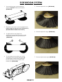
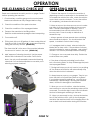
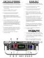
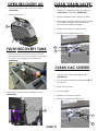
1
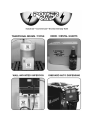
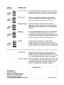
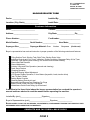
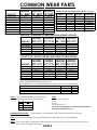
MAGNUM Operator Manual 2009 Version 2.0 R.P.S. Corporation P.O. Box 241 Racine, Wisconsin 53401 Phone: 1-800-450-9824 Fax: 1-866-632-6961 HOW TO USE THIS MANUAL This manual contains the following sections: - HOW TO USE THIS MANUAL - SAFETY - OPERATIONS - MAINTENANCE - PARTS LIST The SAFETY section contains important information regarding hazard or unsafe practices of the machine. Levels of hazards are identified that could result in product or personal injury, or severe injury resulting in death. The HOW TO USE THIS MANUAL section will tell you how to find important information for ordering the correct replacement parts. The OPERATIONS section is to familiarize the operator with the operation and function of the machine. Parts may be ordered from authorized dealers. When placing an order for parts, the machine model and serial number are important. The MAINTENANCE section contains preventative maintenance to keep the machine and its components in good working condition. They are listed in this general order: Refer to MACHINE INFORMATION on page one of this manual, which is filled out during the installation of your machine. - Batteries - Scrub Brushes - Adjusting Squeegee - Service Schedule - Machine Trouble Shooting The serial number of your machine is located on the lower half of the control panel of the machine. (See Picture Below) The PARTS LIST section contains assembled parts illustrations and corresponding parts list. The parts lists include a number of columns of information: Serial Number - ITEM - Column refers to the reference - PART NO. - Column lists the part number - QTY - Column lists the quantity of the part - DESCRIPTION - Column is a brief description - COMMENTS - Column for information not number on the parts illustration. for the part. used in that area of the machine. of the part. noted by the other columns. NOTE: If a service or option kit is installed on your machine, be sure to keep the KIT INSTRUCTIONS which came with the kit. It contains replacement part numbers needed for ordering future parts. * As our policy is one of constant improvement, all information and specifications are subject to change without notice. * STANDARD WARRANTY POLICY (RPS Corporation) RPS Corporation warrants its machines, parts and accessories to be free of manufacturer’s defects for the periods specified below. Warranty will be granted at the sole discretion of RPS Corporation and is subject to final claim and parts review by R.P.S. Corporation and its vendors. This policy is effective January 1, 2010 and is subject to change on production units at a future date. COVERAGE, EXCLUSIONS AND LIMITATIONS: Coverage: All Models sold (Sweepers, Scrubbers, Burnishers) Parts: 36 months / 1,500 hours on “Power On” hour meter Labor: 12 months Travel: 3 months (150 mile maximum) Poly Tanks: 7 Years OEM Parts: 3 months Validity: Fully completed Machine Delivery Form (online or fax) is on record at RPS. Limitation: Warranty will begin on date of machine installation to end-user or 6 months after shipment from RPS Corp to the distributor if unsold at that time. This warranty includes all parts on the machine except normal wear parts. Some of these exceptions are: 1. Any Brooms, Brushes, Pads or Pad Drivers including Center Clip Retainers 2. Floor Seals, Wipers, Splash Curtains, Squeegees or Gaskets. 3. Filters, Dust Collection Bags or Screens 4. The safety pins design to fail in shear, which are a fail-safe device 5. Belts, Hoses or Tubing. 6. Caster Wheels, Tires or internal tire tubes. 7. Vacuum motors with evidence of water/foam passage or more than 450 hours 8. Lights (Strobe, Headlights or bulbs). 9. The Batteries (see below). NOT COVERED: Routine maintenance, adjustments or parts damaged from abuse, neglect, improper use of the machine, or lack of scheduled “daily, weekly, monthly” maintenance in accordance with our published PM Sheets. POLY TANKS: 7 Years Coverage against leakage due to manufacturer’s defect in materials or workmanship. NOTE: Freight coverage for 3-Years under the parts section of warranty. BATTERIES: Warranted through battery manufacturer for One (1) Year (prorated) from the date of delivery. The battery manufacturer approves or denies the warranty coverage after analysis. We rely on solely on their review. NOTE NOT COVERED: Damage from lack of water, failure to use OEM charger, or non-distilled water. TABLE OF CONTENTS MACHINE INFORMATION FORM WARRANTY REGISTRATION FORM MACHINE SPECIFICATIONS COMMON WEAR PARTS SAFETY MESSAGES !!SAFETY PRECAUTIONS!! MACHINE CONTROLS AND FEATURES MACHINE SETUP ADJUSTING & REMOVING SQUEEGEE INSTALLING PAD DRIVER OR BRUSH INSTALLING CYLINDRICAL BRUSHES SIDE BROOM SYSTEM OPERATION ADJ. SOLUTION FLOW & CURTAINS, DRAINING TANKS CLEANING RECOVERY TANK TIP TANK, RAISE & LOWER SQUEEGEE ADJUST DECK HEIGHT, VAC MOTOR & SOLUTION FILTER CHARGING BATTERIES ON-BOARD BATTERY CHARGER "OPTIONAL" MAINTENANCE & STORING MACHINE PREVENTATIVE MAINTENANCE RECORDS LCD SCREEN MENU DISPLAY'S TROUBLESHOOTING PAGE 1 PAGE 2 PAGE 3 PAGE 4 PAGE 5 PAGE 6 PAGE 7-8 PAGE 9 PAGE 10 PAGE 11 PAGE 12 PAGE 13 PAGE 14-15 PAGE 16 PAGE 17 PAGE 18 PAGE 19 PAGE 20 PAGE 21-26 PAGE 27 PAGE 28-29 PAGE 30 PAGE 31-36 MACHINE INFORMATION Please fill this area out at the time of installation for future reference. Model Number_____________________________________________________________ Serial Number:______________________________________________________________ Installation Date:___________________________________________________________ Installing Dealer:__________________________________________________________ Dealer Contact: ___________________________________________________________ Address:____________________________________________________________________ City, State, Zip: ______________________________________________________________ Phone Number:_____________________________________________________________ This operator and parts manual should be considered a permanent part of the unit and should remain with the unit at all times. This operator and parts manual covers all the Magnum series scrubbers. You may find descriptions and features that are not on your particular model. The information and specifications included in this publication were in effect at the time of printing. R.P.S. Corp. reserves the right to make changes without notice or incurring any obligation. To register for warranty, fax your warranty registration form today! FAX # (886)-632-6961 PAGE 1 R.P.S. CORPORATION P.O. BOX 368 RACINE, WI 53401 PHONE: 800-634-4060 MACHINE DELIVERY FORM Dealer: __________________________ Installed By: ______________________ Location: (City, State)_______________ Install Date: ______________________ Customer Information Name:________________________ Contact: _________________________ Address:_________________________ City/State:__________________Zip______ Phone Number :___________________ Fax Number: _____________________ Model Number:___________ Serial Number:______________ Squeegee Size:__________ Squeegee Material: Gum Linatex Hour Meter:____________ Neoprene (circle one) Buyer’s representative has received instruction in proper operation of the following controls and features: Filling Solution Tank, Solution Tank Sight Tube, Solution Drain Valve Adjusting Controls and “Uni-Touch” operation, Double Scrubbing, Squeegee Delay & Vac Timer Recovery Tank Draining and Cleaning, Vac Screen Removal and Cleaning Shroud and Pad Removal Shroud Adjustment Solution Valve and Filter Operation (removal and cleaning) Drain Saver Feature Charging Operation Seat and Steering Wheel Adjustment LCD Screen Display Operation, 3 Hour Meters (keyswitch, brush, traction drive) Tank Tilt Back Feature Parking Brake Override Checking Battery Electrolyte Level Squeegee Hose Removal and Checking For Clogs Battery Guide Poster Hung Up & Reviewed Maintenance Guide Poster Hung Up & Reviewed In addition to the items listed above the buyers representative has received the operator’s manual and been advised to read the manual before operating the machine. Installed By (print)______________________Signature________________ Buyer’s Representative (print)_____________________Signature_______________ BUYER AGREES TO PAY FOR ANY REPAIRS, ADJUSTMENTS, OR SECONDARY TRAINING THAT MANUFACTURER DETERMINES IS EXCLUDED FROM THE WARRANTY COMPLETE AND FAX FORM to 866-632-6961 PAGE 2 MACHINE SPECIFICATIONS SPECS Disk Cylindrical BODY CONSTRUCTION Tank Construction: Frame Construction: Drive Wheel: Casters: Body Dimensions (L x W x H): Width (squeegee): Weight (w/out batteries): Weight (w/ standard batteries): (7/16”) Roto-Poly 3/16” Steel (2) 12” diameter x 3-1/2” (2) 5” diameter x 2” 56” x 24” x 43” 35”, 38” or 45” 489 pounds 967 pounds (7/16”) Roto-Poly 3/16” Steel (2) 12” diameter x 3-1/2” (2) 5” diameter x 2” 56” x 24” x 43” 35”, 38” or 45” 494 pounds 974 pounds 26D - (2) 13 inches 30D - (2) 15 inches 34D - (2) 17 inches BRUSH/PAD SYSTEM Brush/Pad Diameter: Motor Power (standard): Motor Power (HD Option): Brush Speed: Brush Pressure: Brush Pressure Settings: (2) 0.75 hp / 270 rpm (2) 1.0 hp / 270 rpm 270 rpm 0-250 pounds (1-5) automatic 24C - (2) 22” x 5.5” 27C - (2) 25” x 5.5” *30C - (2) 28” x 5.5” *34C - (2) 32” x 5.5” (2) 0.75 hp / 350 rpm (24” & 27”) (2) 1.0 hp / 350 rpm (30” & 34”) 750 rpm 0-250 pounds (1-5) automatic BATTERY SYSTEM Battery AH Rating (Standard): Battery AH Rating (Optional): Battery Run Time: Charger (110v / 60 Hz / auto): 210 AH Up to 325 amp hour Up to 5 hours 24-v / 25-amp 210 AH Up to 325 amp hour Up to 5 hours 24-v / 25-amp SOLUTION SYSTEM Solution Tank Capacity: Solution Flow Rate: 30-gallons 0 - 0.75 gal/min. 30-gallons 0 - 0.75 gal/min. RECOVERY SYSTEM Recovery Tank Capacity: Vacuum Horsepower: Vacuum (Water Lift / Cubic ft/min): 30-gallons 0.8 hp / 3-stage 68” / 72 cfm 30-gallons 0.8 hp / 3-stage 68” / 72 cfm DRIVE SYSTEM Transaxle Description: Speed Control: 0.75 hp, gear / sealed 0 – 230 ft/min 0.75 hp, gear / sealed 0 – 230 ft/min 26” / 26,000 sq.feet / hour 30” / 30,000 sq.feet / hour 34” / 34,000 sq.feet / hour 24” / 24,000 sq.feet / hour 27” / 27,000 sq.feet / hour 30” / 30,000 sq.feet / hour 34” / 34,000 sq.feet / hour PRODUCTIVITY Cleaning Width & Rate/Hour: * HD STANDARD R.P.S. Corporation P.O. Box 368 Racine, WI 53401 Phone: (800) 634-4060 Fax: (866) 901-3335 Copyright R.P.S. Corporation 2006. All rights reserved. Since our policy is one of constant improvement, all specifications are subject to change without notice. PAGE 3 COMMON WEAR PARTS BRUSHES SUPER-GRIT TOUGH-GRIT MIDI-GRIT LIGHT-GRIT POLY (.028) NYLON (.016) TAMPICO PAD DRIVER DIAMOND DRIVER MODEL MODEL MODEL 26"-DISK 30"-DISK 34"-DISK 17-421SS 17-421S 17-421C 17-421PS 17-421P 17-421N 17-421T 17-421D 17-421DD 15-421SS 15-421S 15-421C 15-421PS 15-421P 15-421N 15-421T 15-421D 15-421DD 13-421SS 13-421S 13-421C 13-421PS 13-421P 13-421N 13-421T 13-421D 13-421DD NOTE: # In Disk Column Denotes Pad Size: 13,15, 17 PADS SUPER BLACK BLACK BROWN GREEN BLUE RED WHITE DISK ##422BB ##422B ##422BR ##422G ##422BL ##422R ##422W LEVEL VERY HIGH HIGH HIGH MEDIUM MODERATE MODERATE LIGHT COLOR BLACK BLACK BROWN GREEN BLUE RED WHITE NEW STYLE CYL BRUSHES FOR MACHINE SERIAL #50000 & GREATER MODEL 24"-CYL BRUSHES MODEL MODEL MODEL 27"-CYL 30"-CYL 34"-CYL N/A 225-821S 225-821C 225-821PS N/A 225-821N SUPER-GRIT TOUGH-GRIT MIDI-GRIT LIGHT-GRIT POLY (.028) NYLON (.016) N/A 255-821S 255-821C 255-821PS N/A 255-821N N/A 285-821S 285-821C 285-821PS N/A 285-821N N/A 325-821S 325-821C 325-821PS N/A 325-821N OLD STYLE CYL BRUSHES FOR MACHINES PRIOR TO SERIAL #50000 MODEL 24"-CYL BRUSHES MODEL MODEL MODEL 27"-CYL 30"-CYL 34"-CYL N/A 22-521S 22-521C 22-521PS N/A 22-521N N/A SUPER-GRIT TOUGH-GRIT MIDI-GRIT LIGHT-GRIT POLY (.028) NYLON (.016) TAMPICO N/A 25-521S 25-521C 25-521PS N/A 25-521N N/A N/A 28-521S 28-521C 28-521PS N/A 28-521N N/A N/A 32-521S 32-521C 32-521PS N/A 32-521N N/A EXTRA PAD DRIVER RETAINING CLIP: 40-433 BRUSH REPAIR KIT: 40-423 REPLACEMENT LOCATING CLIP FOR ALL DISK BRUSHES. GUM RUBBER LINATEX SQUEEGEE SIZE'S 32" SQUEEGEE "OPTIONAL". 22-770G 22-770L 35" SQUEEGEE "STANDARD" ON 24", 26" & 27" MACHINES. 25-770G 25-770L 38" SQUEEGEE "STANDARD" ON 30" MACHINES. 28-770G 28-770L NOTE: Squeegee Assemblies (complete) listed below all come with Linatex blades. SIZE 32" 35" 38" P/N 23-7180 25-7180 28-7180 SQUEEGEE KITS INCLUDE: SOAP Heavy Duty Degreaser Citrus Freezer Tire Mark Remover For more soap information call PowerCat 414-745-9337 www.powercatsolutions.com (1) Rear Blade, (1) Front Blade, and (2) Backup Wheels with harware. NOTE: Size is stamped into the top of the painted steel squeegee body on all squeegee's. NOTE: The 32" squeegee is designed for narrow isles and may not have the same water control around tight turns as the larger squeegees. PAGE 4 SAFETY MESSAGES Your safety, and the safety of others, is very important, and operating this unit safely is an important responsibility. To help you make informed decisions about safety, we have provided operating procedures and other safety information in the manual. This information informs you of potential hazards that could hurt you or others. It is not practical or possible to warn you of all the hazards associated with operating this unit. You must use your own good judgment. This machine is intended for commercial use. It is designed to be used on hard floors in an indoor environment, with the recommended pads or brushes. 1. DO NOT OPERATE UNIT: Unless trained and authorized. Unless operator manual is read and understood. If unit is not in proper operating condition. 2. WHEN OPERATING UNIT: Remove loose objects from the floor that may be projected from the revolving brushes. Keep hands and feet away from revolving brushes. Do not operate machine where flammable liquids are present. Use extreme caution when maneuvering. 3. BEFORE LEAVING: Drain Tanks Make sure machine is turned off. Stop on level surfaces. Disconnect batteries. 4. BEFORE SERVICING: Stop on level surface, and secure machine. Disconnect batteries. PAGE 5 !! SAFETY PRECAUTIONS!! WARNING: Always use the charger provided by WARNING: Hazardous voltage. Shock, burns or fire can result. Keep sparks and open flames away. the manufacturer to charge the machine. It is an automatic charger, specifically designed to charge at the appropriate rate. If you must use a different charger, disconnect the batteries before charging. This will prevent damage to the electronic speed controller. WARNING: Charge unit in a well ventilated area, and WARNING: Understand the dynamic braking electrocution can result. Always disconnect the batteries before servicing machine. WARNING: Batteries emit hydrogen gases. Explosion or keep battery compartment open when charging. Explosion or fire could result. WARNING: Battery acid can cause burns. Wear system before you operate the machine on ramps. Machine may coast. WARNING: Do not park the machine on ramps protective eye wear and gloves when servicing batteries. or slopes. WARNING: Do not store outdoors or pressure wash. Prevent electronic components from getting wet. WARNING: The use of parts and solutions other than that recommended by the manufacturer may cause damage or endanger people. WARNING: Dress safely. Do not wear rings or metal wrist watches while working on this machine. They can cause an electrical short, which, can cause serious burns. Do not work on this machine while wearing a tie, scarf or other loose, dangling neckware or clothing. These loose items can tangle in the rotating parts and cause serious injury or even death. WARNING: Do not operate the machine if any parts have been removed or damaged. WARNING: Do not remove, paint over, or destroy warning decals. If warning decals become damaged, they must be replaced. WARNING: Do not operate machine in unsafe condition. If the machine is in need of repair or is in any way unsafe to operate, the matter should be reported immediately to the shift supervisor. Do not operate the machine until it is returned to proper operating condition. WARNING: This machine must only be WARNING: Do not use the machine as a step ladder or chair. WARNING: Only operate this machine from the operators position. It was not designed to carry passengers. operated by trained operator. As part of his or her training, they must read this manual thoroughly. If extra copies are needed, contact your local dealer. WARNING: Always turn off the machine, before leaving it unattended. WARNING: Do not operate this machine on ramps or uneven surfaces. When climbing a ramp, always drive the machine in forward straight up or down the ramp. Never drive across the incline. Do not back down or turn on ramps! PAGE 6 WARNING: Do not operate over electrical floor outlets. May result in serious injury. MACHINE CONTROLS AND FEATURES 1 4 5 9 19 2 3 FIGURE 1. 6 7 10 11 12 13 14 8 20 18 17 FIGURE 2. 15 15 21 22 FIGURE 3. 23 32 31 24 33 30 34 25 26 29 27 FIGURE 4A. 38 39 40 28 36 35 37 FIGURE 4B. PAGE 7 41 CONTROLS AND FEATURES SEE FIGURE 1 1. 2. 3. 4. 5. 6. 7. 8. SEE FIGURES (1-4) ON PAGE 7 MAIN POWER SWITCH: Turns the machine on and off. FORWARD/REVERSE SWITCH (RED): Controls the direction of the Traction Drive, Pull back for reverse. SPEED CONTROL KNOB: Controls the speed of the Traction Drive, Turn counter-clockwise to reduce speed. LCD SCREEN: Lists functions and settings of the machine. (See Page 9) MENU CONTROL: Scrolls through different options on the LCD display, there are 3 different screens. SCRUB DECK DOWN PRESSURE SWITCH: Controls the pressure on the Scrubdeck, push forward for more down pressure. SCRUB DECK SWITCH: Raises and lowers the Scrubdeck. SOLUTION FLOW CONTROL KNOB: Turn clockwise to reduce & counter-clockwise to increase flow. SEE FIGURE 2 9. SQUEEGEE LIFT LEVER: Raises and lowers Squeegee. 10. SPRAY JET (BLUE) (OPTIONAL): Activates Spray Pump for remote Spray Wand. 11. ELECTRIC SQUEEGEE LIFT (GREY) (OPTIONAL): Electronically raises and lowers Squeegee. 12. SIDE BROOM SWITCH (YELLOW) (OPTIONAL): Turns on the Side Brooms. 13. "ON BOARD" SOAP SYSTEM (GREEN) (OPTIONAL): Dispenses soap into Solution Tank. 14. EMERGENCY STOP (OPTIONAL): Shuts off power to the machine. 15. CHARGER PORT: Red 50 used to receive charger input. NOTE: Only use charger provided (24 VOLT ONLY!). 16. KEY SWITCH (OPTIONAL): Turns power on to the machine. 17. SERIAL NUMBER PLATE: Machine identification. 18. WARNING PLATE: Detergent/Water warning. 19. WARNING PLATE: Explosion warning. SEE FIGURE 3 20. TRACTION DRIVE: Propels machine forward/backward. 21. SOLUTION FLOW VALVE: Controls solution flow rate. 22. SOLUTION FILTER: Filters water solution prior to scrubbing. SEE FIGURE 4A 23. DRIVE BUTTON: Depress to drive forward, release to stop. (starts & stops the drive motor) 24. "DRAIN SAVER" STRAINER: Helps prevent clogging of drain ports. 25. VAC SCREEN: Protects Vac Motor from debris. 26. CASTER: Twin casters for stability. 27. MAIN TIRE: Drive Tires. 28. JAWS: Protects Scrubdeck from collision damage. 29. POLYURETHANE ROLLERS: Helps protect machine when scrubbing near walls. 30. TANK-IN-TANK: Solution/Recovery Tank(30 gallons capacity each). 31. SOLUTION FILL LID: Fill port for filling Solution Tank. 32. RECOVERY LID: Used for flushing out Recovery Tank area with fresh water. SEE FIGURE 4B 33. CLEAR COVER: For viewing inside Recovery Tank area. 34. CONTROL PANEL: Machine controls and access to electrical components. 35. RECOVERY DRAIN HOSE: Allows for controlled draining of Recovery Tank. 36. SOLUTION LEVEL INDICATOR & DRAIN TUBE: Shows precise level of cleaning solution in Tank & Drain Port. 37. "ON BOARD" BATTERY CHARGER (OPTIONAL): Recharges Batteries. 38. SQUEEGEE BLADE: Recovers dirty water from floor to be recovered by Vacuum Hose. 39. VACUUM HOSE: Vacuumizes Squeegee. NOTE: Keep free and clear of blockage. 40. SQUEEGEE PITCH ADJUSTMENT: Adjusts pitch of Squeegee. Deflection should be even across entire blade. 41. TANK LATCH: Secures tank to frame. PAGE 8 MACHINE SETUP UNCRATING MACHINE ATTACHING SQUEEGEE Carefully check the crate for any signs of damage and that the batteries are in the unit. To uncrate the machine, remove banding from around the crate. Take off the top and sides and dispose of properly. Carefully roll the machine off of the base. Notify the carrier immediately if concealed damage is discovered. Cylindrical brushhead is screwed to the pallet via screws located in the front solution trough. DO NOT TURN ON MACHINE 1. Lower the squeegee mounting plate by rotating the lift lever "A" clockwise. (SEE BELOW) A UNTIL THESE SCREWS HAVE BEEN REMOVED. (SEE BELOW) CONNECTING BATTERIES 2. Loosen the two knobs "B" on the squeegee and slide them into the slots in the squeegee mounting plate. (SEE BELOW) Your machine is equipped with (2) 12-volt/205 AH, (4) 6-volt/245 AH or (4) 6-volt/325 AH, deep cycle, batteries, which form a 24 volt system. (SEE PICTURE BELOW FOR CORRECT CABLE CONNECTIONS.) 1. Turn all switches to the off position and remove key (if machine is equipped with optional key switch). 2. Turn on main power switch and check the battery condition meter to ensure correct installation. Charge batteries if needed. (SEE BATTERY CHARGING.) B WARNING! Batteries are a possible environmental hazard. B Consult your battery supplier for safe disposal methods. NOTE: Orientation of batteries is critical for cables to reach! 2. Tighten the two knobs, and connect the vacuum hose "C" from the machine to the squeegee. (SEE BELOW) 24-Volts *4 BATTERY CABLE CONNECTIONS* 24-Volts *2 BATTERY CABLE CONNECTIONS* PAGE 9 C 4. You may have to adjust the squeegee pitch. (SEE ADJUSTING SQUEEGEE ON NEXT PAGE.) ADJUSTING SQUEEGEE 1. Turning adjustment knob "A" clock-wise (tightening) will lower tips & raise center. (SEE PICTURE BELOW.) REMOVING SQUEEGEE 1. With the squeegee in the up position, turn machine power off. 2. Disconnect vacuum hose "A" from squeegee and loosen both knobs "B". (SEE BELOW) 3. Pull squeegee assembly rearward from the lifting carrier. A 4. Inspect or repair as needed and reinstall. 2. This squeegee is adjusted too far back and will not pick up on the corners. *note tips off the floor*. (SEE BELOW) 2. 3. 2. This squeegee is adjusted too far forward and will not pick up in the center. *note center spaced off the floor*. (SEE BELOW) B A B REPLACING OR ROTATE SQUEEGEE BLADES FOR SAFETY: Before leaving or servicing machine stop on level surface, turn off machine and remove key. 1. Remove the squeegee assembly from the machine. Remove blade retainer strap and remove squeegee blade. 4. 3. 2. Rotate the squeegee to new edge position or replace as required. This squeegee is adjusted just right with good deflection across the entire rear blade. (SEE BELOW) 3. Install blade on the locating pins of squeegee assembly. 4. Install squeegee retainer strap. 5. Fasten and lock knobs. PAGE 10 INSTALLING DISK PAD DRIVER OR BRUSH 1. Turn on machine power. 4. 2. Raise the scrub deck by depressing the brush switch (O) to the up and off position and turn machine power back off. Select the correct pads or brushes that best meet your cleaning application. Consult your local dealer for assistance. 5. Pad installation: attach pads to pad drivers before connecting drivers to motor hub. center clip "C" should click twice. (SEE BELOW) 3. The machine is equipped with jaws. Remove pin "A" and undo latch "B" on front of jaws to open them. (SEE BELOW) C A 6. Attach brushes or pads to motor hubs. Squeeze the scissor locking device and lift brush up on to the motor drive hub. Make sure the scissors close and lock once the brushes are on. (SEE BELOW) 7. With brushes locked in place, close jaws, secure latch and insert pin. B SCRUB BRUSHES There are many different types of brushes available to cover applications from cleaning heavily soiled floors to polishing. A pad driver is also available to take advantage of the many cleaning pads on the market. Please refer to the following to assist in selecting the proper brush or pad for the work at hand Brush Type Disk Cylindrical ABRASION (10 The Highest) Color Pads Disk Cylindrical Level (10 The Highest) Color Super-grit Tough-Grit Midi-Grit Light-Grit Poly (.028) Nylon (.012) Tampico Pad Driver Super Black Black Brown Green Blue Red White ## 421SS ##421S ##421C ##421PS ##421P ##421N ##421T ##421D ##422BB ##422B ##422BR ##422G ##422BL ##422R ##422W NA ##521S ##521C ##521PS NA ##521N ##521T NA NA NA NA NA NA NA NA Very High High High Moderate Moderate Light Light Not Applicable Very High High High Medium Moderate Moderate Light 10 9 8 6 5 2 1 10 8 7 6 4 3 1 ***FOR CORRECT PAD APPLICATION , CALL YOUR LOCAL DEALER*** PAGE 11 Red/Orange Black Blue/Grey Grey Black White Tan NA Black Black Brown Green Blue Red White INSTALLING CYLINDRICAL BRUSHES 1. Turn on machine power. 7. 2. Raise the scrub deck by depressing the brush switch (O) to the up and off position and turn machine power back off. 3. Disconnect batteries. 3. Remove side access door "D" on each side of scubdeck. (SEE BELOW) Brush driver shown misaligned. (SEE BELOW) Old Style Driver 8. New Style Driver Brush driver shown properly aligned. (SEE BELOW) D 4. Slide brush "E" in onto brush driver on opposite side and spin until you feel it catch and drop in. (SEE BELOW) 5. When the brushes are engaged, replace the brush access door. 6. Lift up on the wipers first to close the side door and depress the latch until the door is secured. NOTE: If the brushes are not fully engaged with the drivers the brushes will be damaged. Do not force the access door back on. This usually indicates improper brush installation. Old Style Driver New Style Driver 9. To adjust the tension of the belts turn adjustment screw "F" clock-wise to tighten, counter-clockwise to loosen. (SEE BELOW) 10. To adjust the height of the wipers loosen the 3 screws "G" and slide wiper blades up or down in the slots. (SEE BELOW) F E G PAGE 12 SIDE BROOM SYSTEM 1. 2. Your machine may come equipped with the "optional" side broom system. (SEE BELOW) 5. Brooms adjusted to low. (SEE BELOW) Flip side broom switch up to engage broom. (yellow toggle on left side of the control panel.) (SEE MACHINE CONTROLS ON PAGE 7.) 6. Brooms adjusted to high. (SEE BELOW) 3. To adjust side broom height turn adjustment screws "A" clock-wise to raise, counter-clockwise to lower the brooms. (SEE BELOW) A 4. A To move side broom system out of the way when not in use just pull the pin "B" on each side of deck and rotate side broom system to the up position and reinsert pin. (SEE BELOW) B 7. Brooms adjusted just right. (SEE BELOW) PAGE 13 OPERATION PRE-CLEANING CHECK LIST OPERATING HINTS Read and understand the safety section on pages 5 and 6 before operating the machine. 1. Observe the amount of solution the machine is dispensing on the floor and adjust to the desired flow. To increase the solution flow rate, rotate the solution control knob counter-clockwise. To shut the solution off completely, just release the drive button. 1. Check battery condition gauge on the control panel. Make sure batteries are fully charged before using. 2. Check the condition of the pads or brushes. 3. Check the condition of the squeegee blades. 4. Transport the machine to the filling station. Raise the scrubhead and squeegee when transporting. 5. Turn machine off. 6. Fill the tank with up to 30 gallons of clean water either at front fill port "A" or rear fill port "B". Access rear fill port by raising the recovery tank lid. (SEE BELOW) *The clear tube "C" at the rear of the machine indicates the amount of water in the tank. (SEE BELOW) 8. 2. Keep an eye on the clear vacuum cover to make sure there is not any foamy buildup in the recovery tank. If excess foam begins to develop, pour a recommended foam control solution into the recovery tank. Foam is usually an indication of excessive soap. 3. Always operate at lower speeds when scrubbing around walls and objects. You should reduce the speed, to maintain control when turning. 4. If squeegee starts to streak, raise and wipe the blades with a clean cloth. If the problem continues, check the blades for wear or damage, and rotate if needed. You need to presweep before scrubbing. Add "approved" cleaning chemical. Use the proper dilution ratio indicated on the bottle. Call if unsure. 5. Change or turn over pads when dirty. Rotate the scrub brushes every week. Note: Use only non-flammable commercial cleaning chemicals. Your authorized distributor can assist you in selecting a proper chemical. 6. Stay clear of objects protruding from the floor, such as sockets, grates, for they will damage the pads and squeegee blades. 7. During brief stops you do not have to turn anything off, the brushes and solution will automatically stop when the drive button is released. A 8. Always keep an eye on your gauges. They let you know the status of a particular system at a glance. If your battery gauge is reading low, you must stop immediately, and recharge. Running the batteries dead, will result in damage to the batteries. B 9. When you run out of solution, raise the brushes, and continue to vacuum the remaining water until it is consumed. The solution sight hose is used to indicate the level of detergent remaining in the tank. 10. When you are ready to stop, pick up the brushes, turn off the solution switch, pick up the squeegee, and drive the machine back to the charging area. Be sure to drain both tanks before storing the machine. C PAGE 14 ONE PASS SCRUBBING SCRUB ONLY (SEE BELOW) 1. Turn on machine power switch "A", make sure the speed control knob "B" is at it's lowest setting. (SEE BELOW) 1. Turn on machine power switch "A" make sure the speed control knob "B" is at it's lowest setting. 2. Lower squeegee by rotating the squeege lift lever "C" all the way to the right (vac motor will turn on automatically.) 2. Lower scrub head to the floor, use the top half of the brush switch "G". 3. Lower scrub head to the floor, use the top half (+) of the brush switch "D". 4. Turn the solution flow adjustment knob "H" to regulate the amount of solution flow. 5. Begin scrubbing by depressing one of the green control buttons "D" on the handle bar. Adjust the speed control knob "B" to the desired setting. 4. Turn the solution flow adjustment knob "H" to regulate the amount of solution flow. 5. Begin scrubbing by depressing one of the green control buttons "D" on the handle bar. Adjust the speed control knob "B" to the desired setting. 6. Once the machine begins to move, check the down pressure on the LCD screen "F". To adjust the down pressure, push toggle switch "I" forward to increase pressure backward to decrease pressure. Start scrubbing at the #1 or #2 marks. Do not use the #4 or #5 marks without management's approval. 7. To operate the machine in reverse, simply pull the forward/reverse switch "E" back towards the handle bar. The reverse speed is set to approximately 50% of the forward speed. 8. To stop the machine, let go of the green control button "D". 6. Once the machine begins to move, check the down pressure on the LCD screen "F". To adjust the down pressure, push toggle switch "I" forward to increase pressure backward to decrease pressure. Start scrubbing at the #1 or #2 marks. Do not use the #4 or #5 marks without management's approval. 7. To operate the machine in reverse, simply pull the forward/reverse switch "E" back towards the handle bar. The reverse speed is set to approximately 50% of the forward speed. 8. To stop the machine, let go of the green control button "D". VACUUM ONLY (SEE BELOW) Turn on machine power switch "A", make sure the speed control knob "B" is at it's lowest setting. 1. 2. A B Lower squeegee by rotating the squeege lift lever "C" all the way to the right (vac motor will turn on automatically.) 3. Begin vacuuming by depressing one of the green control buttons "D" on the handle bar. C D E F PAGE 15 I G H D ADJUST SOLUTION FLOW DRAINING SOLUTION TANK 1. Turn solution valve adjustment knob "A" counter-clockwise to increase solution flow, clockwise to decrease solution flow. (SEE BELOW) To drain unwanted cleaning solution from the solution tank, perform the following steps. (SEE BELOW) 1. Pull the clear sight tube/drain hose "A" off barbed fitting. 2. Rinse out tank and solution flow system with clean water. A A ADJUST CURTAINS/WIPERS 1. For Jaw curtains release latch "A" and remove pin "B" on front of jaws to open jaws. (SEE BELOW.) 2. Loosen curtain band screws "C". 3. To adjust curtain to the desired height just slide the curtain up or down in the slots and tighten screws. 4. Close jaws, reconnect latch and reinsert pin. DRAINING RECOVERY TANK B Always empty recovery tank when refilling the solution tank. You can refill the solution tank while the recovery tank is draining. To drain the recovery tank, remove drain hose from hook at rear of tank and unscrew cap. (SEE BELOW) A NOTE: LEAVE RECOVERY LID OPEN WHEN DRAINING TANK! C 1. For cylindrical side wipers loosen wiper band screws "D". (SEE BELOW) 2. To adjust wiper to the desired height just slide the wiper up or down in the slots and tighten screws. B D PAGE 16 CLEAN "DRAIN SAVER" OPEN RECOVERY LID 1. Release both latches "A" on recovery tank lid. (SEE BELOW) 2. Rotate lid fully open. WITH RECOVERY LID OPEN & TANK FULLY DRAINED 1. Remove 2" squeegee intake hose "A" from "Drain Saver" strainer "B". (SEE BELOW) 2. Remove stainless screen, dispose of debris. 3. Rinse screen with fresh water from the outside to the inside holding screen upside down. This will allow for better cleaning. 4. Replace the screen into the bracket. 5. Replace 2" squeegee intake hose. A A B FLUSH RECOVERY TANK 1. Rinse the recovery tank after every use. This will prevent heavy buildup on the bottom of the tank, foul odors, and clogging of the drain hose. (SEE BELOW) CLEAN VAC SCREEN WITH RECOVERY LID OPEN & TANK FULLY DRAINED 3. After rinsing, reattach drain hose "B" on hook. (SEE BELOW) 1. Remove vac screen retaining clip "A". (SEE BELOW) 2. Pull vac screen and float ball assembly (B) off the vac box. 3. Rinse with hot water. 4. Dry thoroughly. 5. Replace vac screen onto box. 6. Replace and tighten retaining clip. B A B PAGE 17 TIP TANK SQUEEGEE UP 1. Fully drain solution tank. 2. Fully drain recovery tank. 3. Remove squeegee. 4. Unlatch tank latch "A" on each side of machine. (SEE BELOW) 1. 5. Open Jaws. (SEE BELOW) 6. Tip tank back carefully until supported by strap. (strap not shown) (SEE BELOW) To raise the squeegee off the floor rotate squeege lift lever "A" counter-clock-wise all the way to the left. (SEE BELOW) A A SQUEEGEE DOWN 1. To lower the squeegee to the floor rotate squeegee lift lever "B" clockwise all the way to the right. Vac motor will turn on automatically. Use with remote vac wand. (SEE BELOW) B PAGE 18 DECK HEIGHT ADJUSTMENT 1. SOLUTION FILTER To adjust deck height for brush clearance, 1. The solution system has a "INLINE FILTER" "A" to filter out cleaning solution prior to scrubbing. loosen jam nut on adjustment bolt "A", turn adjustment bolt clock-wise to raise deck, counter-clockwise to lower deck. Retighten jam nut. (SEE BELOW) (SEE BELOW) A A VAC MOTOR (SEE BELOW) 1. The machine is equipped with a 24 volt, 3/4 hp, vac motor "A". 2. If foam or water gets past the recovery tank's vac screen/ball system the "UNLOADER VALVE" "B" will drain it from the "VAC BOX" "C". CLEANING SOLUTION FILTER 3. The vac motor has an "optional" "FOAM MUFFLER" "D" available for quiet machine operation. (SEE BELOW) 1. To clean the "SOLUTION FILTER" Unscrew the clear cap "A" from housing "B" and remove the "STAINLESS STEEL" screen "C". 2. Rinse any debris from the screen with clean water. A C 3. Reinstall screen and screw cap back on tightly. D B PAGE 19 B C A BATTERY CHARGING CAUTION:The following instructions are intended for the 24v charger supplied with the machine. Do not use any other charger with this machine. 4 CHARGER SPECIFICATIONS * OUTPUT VOLTAGE OF 24 VOLTS. * OUTPUT CURRENT OF 25 AMPS MAX (STANDARD). * OUTPUT CURRENT OF 36 AMPS MAX (OPTIONAL). * INPUT VOLTAGE OF 110 VOLTS/60 HZ. * AUTOMATIC SHUT OFF CIRCUIT. * MADE FOR DEEP CYCLE BATTERIES. DANGER: Always charge batteries in a well ventilated area. Batteries emit hydrogen gas. Explosion or fire can result. Keep sparks and flame away. Shield eyes when servicing batteries and avoid contact with battery acid. 1. Transport machine to a well ventilated area for charging. 2. Turn the machine off. 3. CAUTION ALWAYS WEAR EYE PROTECTION WHEN BATTERIES ARE EXPOSED. 4. Check the water level through "pro-eye" window in each battery. (SEE TOP PICTURE.) Do not charge the machine unless the water is slightly higher than the plates. If needed, add enough distilled water to just slightly cover the plates. Be careful not to over fill. Batteries can overflow during charging. Replace caps before charging. 5. With the red 50 charger plug connected to the machine "FIRST" (SEE MIDDLE PICTURE.) plug the charger power cord into a grounded 110 volt standard wall outlet "SECOND". (SEE BOTTOM PICTURE.) 6. The charger will automatically begin charging, and automatically shut off when fully charged. (check gauge) 7. After the charger has turned off, unplug the charger from the wall outlet "FIRST", then unplug the red 50 charger plug from the machine "SECOND". 8. Recheck the cell level after charging. If needed, add distilled water up to the correct level. Be certain to replace the caps securely and to wipe off the top of the batteries with a clean cloth. PAGE 20 5 6 ON-BOARD CHARGER RED INDICATOR LIGHT YELLOW INDICATOR LIGHT GREEN #1 INDICATOR LIGHT (CHARGE STATUS & FAULT INDICATOR) GREEN #2 INDICATOR LIGHT (AC PRESENT INDICATOR) OPERATING THE CHARGER The LED Function Chart below describes the charging process. NOTE: The LEDs discussed below in the table are the Charge Status LEDs. NOTE: The AC Present LED green#2 is lit at all times when AC is connected, and off when AC is not connected. Operating Condiiton Display Red = on When the red LED is on, it indicated that your battery is discharged and the model 2820-24 is recharging the battery at the "Bulk" rate (Stage 1). Yellow = off This charging rate is approximately 20 Amps. While the red LED is on, the voltage measured (with the charger on) will Green#1= off be approximately 23 to 28 Volts. If an excessive amount of time is taken to complete this stage, the charger will time out and present a fault indicator. (See section 5.) Red = on Yellow = on When both the yellow and the red LED's are on, it is charging at the "absorption" rate. (Stage 2). During this second charging stage, the charger holds the battery voltage at approximately 29 VDC, and gradually reduces the amount of current delivered to the battery. Green#1 = off If an excessive amount of time is taken to complete this stage, the charger will time out and present a fault indicator. (see section 5) Red = on Yellow = on When all three charge status LEDs are on, the model 2820-24 is charging at a "Finish" rate of 10 Amps, (Stage 3). The "Finish" stage will charge the battery up to approximately 30.5-31 VDC. Green#1 = on If an excessive amount of time is taken to complete this stage, the charger will time out and present a fault indicator. (see section 5.) Red = off When the green#1 LED is on, and red and yellow are off, the charge cycle is completed and the battery is ready for use. At least 100% of charge has been returned to the battery. If the battery voltage falls below approximately 24 VDC, the charger will automatically restart the charge process. Yellow = off Green#1 = on PAGE 21 ON-BOARD CHARGER TROUBLESHOOTING Problem 1. Red LED stays on for more than 18 Hrs. Cause 1. One or more defective or damaged cells. 2. Charger has reduced its output voltage below the normal level due to a DC overload or a DC short. 3. On-board DC systems are drawing more current than the charger can replace. 4. Excessive ambient temperature has forced the charger to cutback output current in order to self protect. 2. The red and yellow LED's 1. On-board Dc systems are drawing stay on for more than in excess of 10 amps. 10 Hrs. 2. One or more defective or damaged cells. 3. Extremely low AC voltage at the battery charger. 3. Green #1 LED stays on 1. Open DC output fuse. when the battery is known 2. Faulty or contaminated terminal to be low. connections. 3. One or more defective or damaged cells. 3. The AC Present Green#2 1. No AC power available at the LED does not turn on when charger. AC power is applied. 2. Component failure. 4.The yellow LED is blinking continuously. 5. The red LED is blinking continuously. Solution 1. Load test the batteries and replace if necessary. 2. Remove the source of the overload or short. Disconnect the charger's black (NEGATIVE) ring terminal from the battery. Reapply AC power and the green LED only should now light. 3. Turn off all DC equipment while charging. 4. Determine the cause of the excessive ambient temperature and correct. 1. Turn off all DC equipment while charging. 2. Load test the batteries and replace if necessary. 3. Apply a higher AC voltage source or reduce the length of the extension cord. 1. Replace DC output fuse with a Bussmann (ABC-30 or MDA-30.) 2. Clean and tighten or repair all terminal connections. 3. Load test the batteries and replace if necessary. 1. Connect AC power or reset the AC breaker on the main panel. 2. Return charger to R.P.S. Corp. 1. Charge cycle has timed out, charging 1. See fault codes below. process took an excessive amount of time. 1. Corrupt Microprocessor memory. 1. See fault codes below. 2. Return charger to R.P.S. Corp. Fault Codes: ● Flashing red LED: Corrupt program memory in microcontroller detected, charger microprocessor has become corrupted. Charger must be returned to R.P.S. Corp. ● Flashing yellow LED: Timer has expired. The 2820-24 uses a timer to independently monitor each mode of the charge cycle: bulk, absorption, and finish. If the timer expires during any of these modes of the charge cycle, there could be a problem with the battery set. The timer may expire if there is a damaged battery cell in the battery set, an abnormally high ambient temperature at the charger, or some other external fault, which prevents completion of charge cycle. These problems need to be addressed by user intervention. Charger must be AC powered down in order to reset fault condition. Before resetting the charger, investigate potential problems with battery or other external faults. Once external problem is resolved, reconnect charger output cable fuse and reconnect AC power. 5. MAINTAINING THE CHARGER Periodically clean both battery terminals with baking soda and tighten all connections. No other maintenance on the charger is required. PAGE 22 BATTERY CHARGER OPERATING MANUAL GENERAL INFORMATION AND WARNING • Electronic automatic battery charger with microprocessor suitable for any battery type. • Fully automatic charging cycle with electronic setting; protected against overload, short‐circuit at clamps and reversed polarity. • Never disconnect the battery while charging: this could cause sparks. • Never use the equipment in the rain, in areas used for washing and in damp areas. • Before starting to charge, make sure the voltage of the equipment suits the voltage of the battery and that the selected charging curve (for lead‐acid free batteries and airtight gel batteries) is correct for the type of battery to be charged. In addition, make sure the rated input voltage of the charger suits the available supply voltage and the system is equipped with grounding. • If necessary, replace the fuse with another of the same type and value as indicated on the rating plate. • Pay attention to any remarks of the battery manufacturer. For lead‐acid batteries with liquid electrolyte: • Control the water level after each charging process. • Refill with distilled water only. • Caution! The gases generated during charging are explosive. Do not smoke in the vicinity of the batteries. When working with cables and electrical equipment, avoid open flame and sparks. • Attention: Use protective glasses and gloves during battery maintenance. Battery acid causes injuries. In case of contact with battery acid, wash the affected parts with a lot of fresh water and consult a doctor if necessary. CONTROLS (see figure behind the cover) 1. Three‐digit display + symbol (1), to view A =the charging current, U = the battery voltage, h = the charging time, C = the charging ampere‐hours [AH], E = the energy used [KWh]. 2. Button for the Selection of the display mode (2): A, U, h, C, E. After about 10 seconds the display returns to the visualization of the charging current. 3. Red control indicator (3): when it is on, the charging cycle has started. 4. Yellow control indicator (4): when it is on, the final phase of the charging cycle has started. 5. Green control indicator (5): when it is on, the charging cycle has finished. OPERATION • Plug the cord into the socket. • Connect the battery, checking the polarity. • Now, the battery charger’s display will show a sequence of details on the charger’s internal programming: after the name “SPE”, it will show the software release installed in the equipment, then, in sequence, the following parameters: battery voltage, charging current, charging curve number, and finally the words “GEL” or “Acd” depending on the set up charging curve being suitable for airtight gel batteries or lead‐acid batteries. Make sure the type of batteries to be charged (gel or lead‐acid batteries) matches the displayed details (“GEL” or “Acd”, respectively). If it doesn’t, contact our dealer. Now, a test is run on the battery voltage to decide if the charging process should be started or not. If the battery is not connected to the battery charger, the display will show the word “bat”. The word will stay on, even if the test is failed (for instance, reversed polarities or incorrect battery connection). If the test is passed, the display will show the battery voltage for approximately 5 seconds and the battery will begin to *continued on next page* PAGE 23 BATTERY CHARGER be charged. The charging cycle progress will be shown by red (3), yellow (4), and green (5) LED indicators. At the end of the charge, when the green indicator (5) is on, unplug the cord from the socket and operate the machine. PROBLEMS SOLUTIONS AND CHECKS The battery charger does not switch on. Check that the plug is connected to the supply mains and that the fuse is efficient. The charging cycle does not start and the Check the connection to the battery and polarity. message “bat” is displayed. The yellow indicator (4) will not light up even Check the battery for possible faulty components. 15 hours from the starting of the charging cycle, and the display shows E03. The message E01 is displayed. This means that the maximum voltage admissible by the battery has been exceeded. The charging is interrupted. If the battery charger is provided with a safety This means that the maximum temperature has been thermostat and the message E02 is displayed. exceeded. The charging is interrupted. The message E03 is displayed. This means that the maximum time for the charging phase has been exceeded. The charging is interrupted. The message SCt is displayed. This means that the total safety timer has interrupted the charging. The message Srt is displayed. This signals a possible internal short circuit. PAGE 24 Power Cat 24 Volt 25 Amp Sealed Battery Charger The Power Cat 2425S is a sealed high frequency electronic battery charger with an on board microprocessor that can be programmed for different types of batteries. The charger features a fully automatic charging cycle and has built in protection against short circuits and reverse polarity. THE CHARGER UNIT The charger is equipped with a remote “EZlamp” 3 LED charge state indicator, located on the side of the central command, to show charge cycle information as well as diagnostic codes. Charge Status LEDs OPERATION The 2425S is initially switched on by plugging the unit into the wall. The “EZlamp” charge state indicator then displays whether the unit is set for flooded lead or AGM type batteries by flashing the corresponding LEDs. For flooded lead batteries the “EZlamp” will display ONLY the RED LED flashing for about 5 seconds. For AGM batteries the “EZlamp” will display a flashing GREEN & RED LED for about 5 seconds. *continued on next page* PAGE 25 Power Cat 24 Volt 25 Amp Sealed Battery Charger EZlamp Code Charger Phase Flashing RED Internal charger check – “Flooded Lead Settings” Flashing RED & GREEN Internal charger check – “AGM Settings” Steady RED Indicates first and second phase of charge Steady YELLOW Indicates finish charge in progress Steady GREEN Indicates charge cycle is complete TROUBLE SHOOTING In the event that there is a problem with charger here is a simple trouble shooting guide. If the unit does not power on, assure that the plug for the charger is placed firmly in the wall receptacle and that that the circuit breaker for that receptacle is not blown. Watch the “EZlamp” indicator to see if any LEDs illuminate when it is plugged in. If no LEDs light try a different power cord. If this does not fix the problem the charger needs to be replaced. EZlamp Fault Codes Problem - Continuous flashing RED Solution No connection to battery - Battery connected in -Check connections to battery reverse - Poor Connection - Check all connections - Verify battery was not disconnected during charge Flashing RED & YELLOW - Problem with battery - Check battery - Verify battery electrolyte levels (lead acid only) PAGE 26 Maintenance Daily Maintenance Yearly Maintenance 1. Remove and clean pads or brushes. Never use soiled pads when cleaning. Replace pads when they become packed with residue. 1. 2. Remove and clean debris from the float shut-off screen and drain saver located inside the recovery tank. Storing Machine 3. Drain and rinse tanks thoroughly 4. Inspect vacuum hose for any objects obstructing the air flow. 5. Raise squeegee and wipe blades with a clean cloth. Store squeegee in the raised position to prevent damage or setting of the blades. 6. Wipe down machine if needed. Use a nonabrasive, non solvent cleaner, or a clean damp cloth. 7. 1. Be sure to flush the tanks out completely. To thoroughly flush out any solution chemicals in solution line and valves, refill solution tank with a few gallons of warm clean water and run machine until tank is empty. 2. Open the recovery tank lid to promote air circulation. 3. Raise brushes and squeegee. Checking Battery Specific Gravity Use a hydrometer to check the battery specific gravity. Recharge the batteries if needed. Weekly Maintenance 1. Check battery water level in each cell of the batteries, and fill as needed. Always use distilled water to refill batteries. Batteries should be filled approximately 3/4" to 1" above the plates. Overfilling will cause the batteries to leak during charging. The charging process creates gas bubbles inside the battery, which effectively increases the volume of the electrolyte. 2. Checking Gravity A. Hydrometer B. Battery Note: do not take readings immediately after adding distilled water, if water and acid are not thoroughly mixed, the reading may not be accurate. Check the hydrometer against this chart Clean battery tops to prevent corrosion. 3. Rotate brushes. Rotate the left to the right and right to left. On cylindrical models from front to back, or end to end if using different materials. 4. Drain and rinse tanks thoroughly. To thoroughly flush out any solution chemicals in solution line and valves, refill solution tank with a few gallons of warm clean water and run machine until tank is empty. Monthly Maintenance 1. Check scrub head and squeegee lifting cables for wear and spring tension. 2. Check machine for water leaks and loose nuts and bolts. 3. Check to see if battery cables are tightened (Tighten if needed) 4. Call your local dealer for yearly maintenance Check parking brake PAGE 27 SPECIFIC GRAVITY BATTERY CONDITION @ 80v F (27vC) 1.265 1.225 1.190 1.155 1.120 100% CHARGED 75% CHARGED 50% CHARGED 25% CHARGED DISCHARGED Note: if the readings are taken when the battery electrolyte is any temperature other than 80vF (27vC), the reading must be temperature corrected. To find the corrected specific gravity reading when the temperature of the battery electrolyte is other than 80vF (27vC): add (+) to the specific gravity reading 0.004 (4 points), for each 10vF (6vC) above 80v (27vC). subtract (-) from the specific reading 0.004 (4 points), for each 10vF (6vC) below 80vF (27vC). PREVENTATIVE MAINTENANCE RECORDS CUSTOMER INFORMATION CUSTOMER ADDRESS CITY STATE ZIP CODE MACHINE INFORMATION MODEL # WORK ORDER# SERIAL # HOUR METER: BATTERY CONDITION Cell #1 Cell #2 Cell #3 Cell #4 Battery # 1 Hydrometer Battery # 1 Water Condition Battery # 2 Hydrometer Battery # 2 Water condition Battery # 3 Hydrometer Battery # 3 Water Condition Battery # 4 Hydrometer Battery # 4 Water condition Clean Battery Tops. Check Battery Cable and Terminal Condition NOTES: BRUSH CONDITION Scrub Brush Fiber Length Rotated Brushes Brush Drive Sockets Good Worn Needs Replacement Drive Hubs Good Worn Needs Replacement CHECK OPERATION AND CONDITION OF: IN SPEC REPAIR PROBLEM Main Power Switch or Key Switch Handle Bar Switches Speed Potentiometer Reverse Switch LCD Display Page Switch Brush Pressure Switch Brush Pressure Managers Lock Out Reverse Switch Brush Switch Brush Deck Lift System Brush Motor Brush Drive Belt Solution Potentiometer Solution Solenoid Vacuum Switch Vacuum Motor Performance Vacuum Filter Recovery Drain Hose & Plug Squeegee Lift System Squeegee Adjustment continued on next page PAGE 28 Cell #5 Cell #6 PREVENTATIVE MAINTENANCE RECORDS CHECK OPERATION AND CONDITION OF: IN SPEC REPAIR PROBLEM IN SPEC REPAIR PROBLEM IN SPEC REPAIR PROBLEM Spray Jet Switch Spray Jet Pump, Hose & Nozzle Battery Charger Connectors Battery Charger CLEAN AND/OR LUBRICATE Solution Filter Squeegee Pivot Points & Knobs Scrub Deck Linkage Caster grease fittings Squeegee Knob Threads Squeegee Pivot Points Brush Head Pivot Points VISUALLY INSPECT: Solution Tank Condition Recovery Tank & Lid Condition Drain Saver Vacuum Float Vacuum Motor Brushes Vacuum Hoses Vacuum Filter Solution Hoses Squeegee Tool and Throat Squeegee Blades Blade retainers & Hardware Squeegee Wheels Brush Skirts Brush Motor Brushes Brush or Pad Driver Condition Drive Wheel Condition Caster Condition COMMENTS Technician's Name Technician's Signature Date Customer's Name: Customer's Signature Date ©2006 R.P.S. Corporation continued from previous page PAGE 29 LCD Screen Menu Displays SCREEN # 1 (Operator) SCREEN #3 (Maintenance) 5 6 7 1 11 4 2 10 3 1 SCREEN W/ERROR CODE 1 8 11 2 9 ***Use green menu selection button on control panel to change screens*** 1. Battery level indicator - Indicates the energy level remaining in the batteries. (Shown on all menu displays) 2. Scrubdeck down pressure gauge - Sets the down pressure on the brushes. 3. Vacuum on - Indicates the vacuum is "on". 4. Scrub motors on - Indicates the brush motors are "running". 5. Key switch hour meter - Tells you the total hours the machine has been on. 6. Scrub brush hour meter - Tells you the total hours the brush motors have been used. 7. Transport hour meter - Tells you the total hours the drive system has been used. 8. Error warning symbol - Indicates when there has been a diagnostic code error. 9. Diagnostic code - When the machine has detected an error it will display the warning symbol 10. Water on - Indicates the solution flow is "on" and a diagnostic code which tells you what's wrong. 11. Solution level - Indicates the gallons per minute (G.P.M) 0 - 1.0 . (For common error codes and descriptions see pages 27 & 28.) PAGE 30 TROUBLESHOOTING CENTRAL COMMAND II NOTE: This machine is operated by a sophisticated electronic "CONTROLLER" that has many fail-safes within it. The controller self-analyzes problems and flashes a four-digit numeric code of what is wrong in the LCD window. Most of these codes require a technician's attention. You should not attempt repairs you are uncomfortable with, especially if you are not used to working on electronics. The complete list of codes is published in the simplified electronic troubleshooting manual, which is available to technical people. However, we have included the basic codes that you can usually resolve yourself. 1. 1E03 AND 1E04 ERROR. Check the small safety switch next to the red plug below the dashboard. This switch will turn off the traction drive and brushes as a safety feature while the charger is plugged in. The switch may be stuck, or the plug twisted at an angle, engaging the switch. This code will also flash if the wiring becomes very wet. In this case, either wait until the wiring dries out, or call a technician. 7601 AND 7602 ERROR. Pads or brushes current over load. This can can occur when the pads/brushes hit a bump in the floor. To restart the pads, turn off the key and turn it on again. To avoid this error, either slow down on bumpy parts of the floor, or reduce downpressure on the pads or brushes. 2. 3. 1600 ERROR. Voltage exceeds the maximum. Either the batteries are mis-wired, or the charger is still plugged into the machine. 4. 7700, 7701, 7702, AND 7703 ERROR. The vacuum motor has exceeded it's authorized power limit. Turn off main power switch and turn on again to clear. PAGE 31 TROUBLESHOOTING CENTRAL COMMAND II 5. 7900 AND 7901 ERROR. The emergency stop button is out. 6. HIGH THROTTLE ERROR. You pressed the drive button before turning on the key. Turn off the key, release the drive button and try again. 7. 2C00 AND 2C01 ERROR. Low voltage warning. Voltage has dropped down below the minimum required to operate the machine. If you wait a few minutes, the batteries may coast up a bit in voltage, allowing you to drive very slowly to the recharge station. 8. 7802 ERROR. The traction motor was used to climb a ramp, and was running up the ramp for more than the 60 seconds allowed for this. Turn off the key, turn on again, and continue. You should not use this machine to climb ramps so steep and so long that this code comes up repeatedly, or you could overheat and damage the traction motor. 9. All other error codes. Turn off the main power switch and disconnect the positve battery cable from the batteries for more than one minute (the time is needed to drain the controller's on-board capacitor). Reconnect the cables being sure they are tight; too loose will burn the batteries. If you overtighten the cables you can damage the battery's lead terminal. Try again. 10. If the problem cannot be solved by any of these remedie's call your local dealer's service department. PAGE 32 TROUBLESHOOTING CENTRAL COMMAND II V4 Code 0700 0701 0702 0704 0705 0706 0810 0811 0812 0813 0814 0815 0816 0817 0818 0A01 1310 Fault Description Bias Voltage Error Mid Rail Voltage High Mid rail bias voltage high 12V supply failure 2.5 V reference error High reference ground fault Throttle High reference error Throttle Max Wiper Difference Error Throttle Max Pull Down Difference Error Throttle Max Pull Safe Difference Error Throttle Reference Error Throttle Lo Reference Error Throttle Hi Reference ISO Error Throttle Lo Reference ISO Error Throttle Error: Both have Readings Power down error Excessive Current Trip 1311 Brush head actuator, excessive current 1312 Squeegee actuator, excessive current 1313 Solution valve circuit, excessive current 1314 1318 131C Soft Aux 4 Over current Occurred Soft Brake light Over current Occurred Backup Alarm Over current occurred 1321 Aux 1 (Brush Actuator) Over current 2 Occurred 1322 Aux 2 (Squeegee Actuator) Over current 2 Occurred 1400 Bridge Fault 1 - Brush or traction motor not in correct voltage range. Bridge Fault 2 - Voltage difference on traction bridge too great Brush Bridge Fault - Battery/Brush bridge voltage difference too great 1401 1402 1411 1412 1413 1414 1500 1501 1502 1503 1504 1507 1600 1D02 Brush actuator positive wire is shorting Brush actuator negative wire is shorting Squeegee actuator positive wire is shorting Squeegee actuator negative wire is shorting Brake Fault - Solenoid brake circuit is open Brake Fault - Solenoid brake circuit is shorted Brake Fault - Brake Over Current Error Solenoid brake driver fault Solenoid brake interlock fault Brake Over current High Battery Error Spec Change Trip 1E03 1E04 1E06 2C00 2C01 2C02 2C03 2F01 3A00 3100 3101 3102 3103 7000 Inhibit activated Inhibit Activated 2 Inhibit Input Out of Range Low Battery Error Low Battery Error--2 Battery lockout occurred Battery Lockout occurred--2 Throttle Displaced Error Bad Program Settings Low bridge voltage Traction bridge fault Brush/Vac bridge fault Waiting for bridge to charge Startup With Push Selected Course of correction High reference signal is grounded 5 Volt reference is Contacting 0 Volt Reference For all Throttle Diagnostic Codes Check throttle wiring for shorts or opens. Repair or replace as necessary. If diagnostic code is not cleared, then replace the throttle potentiometer Check the wiring to the the main power switch. This code indicates rapid power cycling Current Draw on Control exceeds maximum limit of 250 amps Resistance in the machine's Main Breaker and/or battery cable to control Gives a false reading to the control. Device connected to the brush head actuator has exceeded maximum limit of 21 amps surge value and 7 amps continuous. Check that the arms are not too tight (torque = 25 inch lbs, almost finger loose). check that actuator system is not binding. Device connected to squeegee actuator (on riders) has exceeded max limit of 21 amps surge value and 7 amps continuous load. Check that the arms are not too tight (torque = 25 inch lbs, almost finger loose). check that actuator system is not binding. Current exceeded seven amps max. Check valve operation. Coil may be corroded, or short in wires. Aux 4 is not used by us at this time. Brake light circuit not used by us at this time. Backup alarm drew more than 2 amps max allowed. Check inline resistor on some models. If resistor is bad, remove it, and put piece of duct tape over speaker of alarm. (Reverse EMF from the echo is causing the problem) Brush actuator exceeded 12 amps for less than 0.1 sec. See notes for 1311 Squeegee actuator exceeded 12 amps for less than 0.1 sec. See notes for 1312 Possible short between B+ and the high amperage outputs Find appropriate wire and remove short. Find appropriate wire and remove short. Find appropriate wire and remove short. Find appropriate wire and remove short. Parking Brake is disconnected or coil of brake is open. Parking Brake coil or wiring is shorted. Parking brake coil is shorted internally or wiring too it is shorted Parking Brake is drawing too much power. Check wiring and brake. Battery voltage is too high. Batteries hooked up wrong, or still on charger. This is normal--comes up when you reprogram the control. Turn key off and on to reset the program. Inhibit is power signal intended to turn off control. We don't use it. Inhibit is power signal intended to turn off control. We don't use it. Inhibit circuit voltage is too low or high to work. We don't use Inhibit. Voltage in battery is too low (18 volts min on 24V system; 28V on 36V system) Recharge the battery in either case. check voltage under load to see if bad cell is pulling down voltage. Pedal was pushed before key turned on. Not a problem. Restart machine. You reprogrammed the control with settings that are not authorized. Probable short circuit of output device or wiring Freewheel input signal selected at startup. Disconnect freewheel switch. *CONTINUED ON NEXT PAGE* PAGE 33 TROUBLESHOOTING CENTRAL COMMAND II V4 *CONTINUED FROM PREVIOUS PAGE* 7001 Push Activated in Drive Mode 7500 7501 7600 7601 Throttle Comms Time Out LCD Module settings corrupt Brush motor not connected Soft Brush Current Fold back 7602 7603 7604 7605 Soft Brush Current Foldback--2 Soft Brush Current Foldback--3 Brush Inhibit is on Brush startup over current detection 7700 7701 Soft Vacuum Motor Disconnected Error Vac Motor Current Fold back 7702 7703 7800 Soft Vacuum Current Foldback--2 Soft Vacuum Current Foldback--3 Traction Motor Fault No. 1 7801 7802 Traction Motor Over current Error Soft Traction Motor in Fold back State 7803 7880 7900 7901 8000 Motor Line Voltages Instability Timeout Traction Speed Input Out of Range Emergency Stop Error Soft Belly Button Actuated Service Mode 9000 0003 0100 0204 0A01 0B02 1704 1705 1706 Brushes not fitted Possible terminal short in system Freewheel input signal activated while driving. Disconnect freewheel switch. NOTE: As of this reading, we do not use Freewheel. This permits pushing machine more easily b y disconnecting traction motor from control. Problem with LCD dash module or with wiring to it. Check and replace as necessary. Disconnect batteries and wait 2 minutes to reconnect Check for open circuit Too much load on brush motor. May be from hitting a bump or wire tangled in brush drive mechanism. Possible wiring or brush motor short. Same as above. Same as above. We do not use Brush Inhibit at this time. You may have started brushes on carpet or rubber or other high resistance material. This may have stalled motor before actuator could react to lift brush head up. If chronic problem, call Factory to discuss reprogramming machine for application. Check wiring to vac motor. On 390, check wiring to Hella relay for vac motor Too much amp load on vac circuit. Check wiring. May come from picking up large column of water. Same as above Same as above Check traction motor wiring and connectors. Include connector at steering pivot under floor cover! Too much current due to bad motor or wiring to motor. Traction motor being overloaded, or ramp climbing that took longer than 60 seconds. (Fold back means normal low amp setting to motor. There is one minute ramp climbing surge that may be 4 times as high as the fold back rate). May be loose wire at motor or at control. Possible motor problem Throttle setting wrong for motor speed. Check throttle pot. and wiring. Emergency Stop Button is Actuated when you tried to move. Optional button. Belly Button Switch activated. We don't use this. Service Timer Limits have been reached. We don't normally use them; they are dealer option. Check brush deck to make sure brushes are on, and on securely. For all of these Diagnostic Codes: 1. Turn off keyswitch and disconnect battery for two minutes, using your watch to measure time. 2. When you reconnect battery, you must see a spark. This shows the control's on-board capacitor has been discharged and has been refilled. 3. Restore the battery connection. Make sure battery cable is on tight before trying machine or you could burn battery posts and cable. 4. Turn on machine. If diagnostic code still shows, then replace the control. PAGE 34 TROUBLE SHOOTING PROBLEM CAUSE SOLUTION NO POWER, NOTHING OPERATES FAULTY POWER SWITCH BATTERIES NEED CHARGING FAULTY BATTERY LOOSE BATTERY CABLE MAIN CIRCUIT BREAKER TRIPPED CONTACT LOCAL SERVICING DEALER SEE CHARGING BATTERIES REPLACE BATTERY TIGHTEN LOOSE CABLE WAIT 5 MINUTES FOR AUTO RESET DETERMINE CAUSE AND CORRECT BRUSH MOTOR(S) DO NOT OPERATE GREEN BUTTON IS NOT DEPRESSED CIRCUIT BREAKER TRIPPED DEPRESS BUTTON ON HANDLE BAR RESET & REDUCE PRESSURE DETERMINE CAUSE AND CORRECT CONTACT LOCAL SERVICING DEALER CONTACT LOCAL SERVICING DEALER CARBON BRUSHES WORN FAULTY BRUSH MOTOR OR WIRES VACUUM MOTOR DOES NOT OPERATE FAULTY VACUUM SWITCH CIRCUIT BREAKER TRIPPED FAULTY VACUUM MOTOR CARBON BRUSHES WORN INSUFFICIENT SOLUTION FLOW SOLUTION TANK LOW FLOW KNOB TURNED DOWN SOLUTION FILTER CLOGGED SOLUTION LINE CLOGGED SOLUTION VALVE CLOGGED PAGE 35 REPLACE SWITCH RESET & CHECK HOSE DETERMINE CAUSE AND CORRECT CONTACT LOCAL SERVICING DEALER CONTACT LOCAL SERVICING DEALER REFILL SOLUTION TANK TURN KNOB MORE OPEN REMOVE COVER AND CLEAN REMOVE AND BLOW OUT WITH COMPRESSED AIR REMOVE COVER AND CLEAN TROUBLE SHOOTING PROBLEM CAUSE SOLUTION NO SOLUTION FLOW NO SOLUTION IN TANK SOLUTION SWITCH OFF SOLUTION SCREEN CLOGGED FAULTY SOLUTION SOLENOID FAULTY SOLUTION SWITCH FILL SOLUTION TANK TURN SOLUTION SWITCH ON REMOVE AND CLEAN SCREEN CONTACT LOCAL SERVICING DEALER CONTACT LOCAL SERVICING DEALER POOR WATER RECOVERY RECOVERY TANK IS FULL BALL/SCREEN IS CLOGGED VACUUM HOSE IS CLOGGED SQUEEGEE IS CLOGGED SQUEEGEE BLADE IS WORN FAULTY VACUUM HOSE VACUUM MOTOR GASKET TORN TANK GASKET FAULTY DRAIN PLUG LOOSE VAC MOTOR FAULTY BATTERY CHARGE LOW EMPTY RECOVERY TANK REMOVE SCREEN AND CLEAN REMOVE DEBRIS REMOVE DEBRIS ROTATE OR REPLACE BLADES CONTACT LOCAL SERVICING DEALER CONTACT LOCAL SERVICING DEALER CONTACT LOCAL SERVICING DEALER TIGHTEN PLUG CONTACT LOCAL SERVICING DEALER CHARGE BATTERIES OVERNIGHT POOR WATER RECOVERY ON TURNS WIPERS WORN WIPERS CHATTER SQUEEGEE SWING IS BINDING INCORRECT SQUEEGEE SIZE REPLACE WIPER MATERIAL TIGHTEN PIVOT POINTS CONTACT LOCAL SERVICING DEALER CONTACT LOCAL SERVICING DEALER TIRES NOISY BEARING DRY FAULTY HUBS GREASE BEARINGS CONTACT LOCAL SERVICING DEALER POOR TRACTION EXCESSIVE BRUSH PRESSURE WORN DRIVE TIRE HEAVY SOAP CONCENTRATION REDUCE PRESSURE WITH SWITCH REPLACE TIRES CONTACT LOCAL SERVICING DEALER SHORT RUN TIME BATTERIES RUN DOWN BATTERIES STILL DOWN BATTERIES LOW ON WATER CHARGE BATTERIES TWICE CONTACT LOCAL SERVICING DEALER FILL WITH DISTILLED WATER TO 3/4" ABOVE THE LEAD PLATES CONTACT LOCAL SERVICING DEALER BATTERIES OVER CYCLED PAGE 36