1
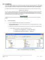
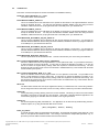
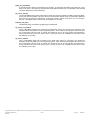
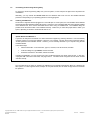
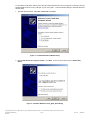
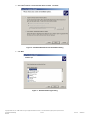
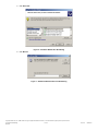
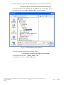
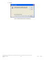
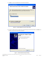
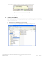
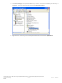
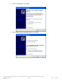
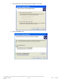
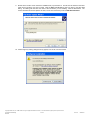
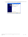
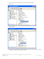
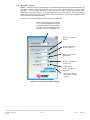
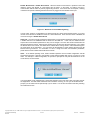
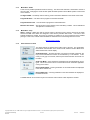
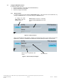
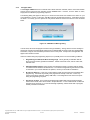
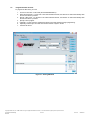
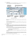
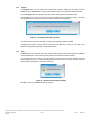
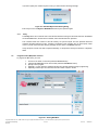
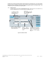
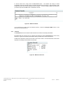
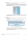
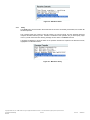
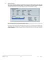
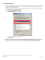
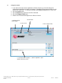
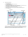
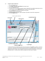
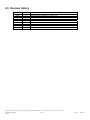
Avnet Programming Utility User Manual Copyright © 2006 Avnet, Inc. AVNET and the AV logo are registered trademarks of Avnet, Inc. All other brands are property of their respective owners. Avnet Electronics Marketing Released 1 of 46 Rev 4.0.5 06/28/2010 Table of Contents Introduction ............................................................................................................................................................................... 4 1.0 2.0 Installation ................................................................................................................................................................................. 5 2.1 Installing Host Software ........................................................................................................................................................ 5 2.2 Installed Files........................................................................................................................................................................ 6 2.3 Uninstalling the Avnet Programming Utility ........................................................................................................................... 8 2.4 Installing the USB Driver ...................................................................................................................................................... 8 2.5 Updating an existing USB Driver ........................................................................................................................................ 15 3.0 AvProg Host Interface ............................................................................................................................................................. 22 3.1 Default Interface and Common Controls ............................................................................................................................ 22 3.1.1 Main Menu – File ................................................................................................................................................................ 22 3.1.2 Main Menu – Options ......................................................................................................................................................... 23 3.1.3 Main Menu – Mode ............................................................................................................................................................. 25 3.1.4 Main Menu – Help .............................................................................................................................................................. 25 3.1.5 Serial Console Controls ...................................................................................................................................................... 25 3.2 Configure FPGA Mode Controls ......................................................................................................................................... 26 3.2.1 Bit File Controls .................................................................................................................................................................. 26 3.2.2 Configure FPGA ................................................................................................................................................................. 27 3.3 Program SPI Flash Controls ............................................................................................................................................... 28 3.3.1 SPI File Controls................................................................................................................................................................. 29 3.3.2 Load Server ........................................................................................................................................................................ 29 3.3.3 ID Check ............................................................................................................................................................................. 30 3.3.4 Erase .................................................................................................................................................................................. 30 3.3.5 Program .............................................................................................................................................................................. 31 3.3.6 Read ................................................................................................................................................................................... 31 3.3.7 Verify .................................................................................................................................................................................. 32 3.4 Program Parallel (BPI) Flash Controls ................................................................................................................................ 32 3.4.1 BPI File Controls................................................................................................................................................................. 33 3.4.2 Load Server ........................................................................................................................................................................ 34 3.4.3 ID Check ............................................................................................................................................................................. 35 3.4.4 Erase .................................................................................................................................................................................. 36 3.4.5 Program .............................................................................................................................................................................. 36 3.4.6 Read ................................................................................................................................................................................... 37 3.4.7 Verify .................................................................................................................................................................................. 38 3.5 Measure LX16 Power ......................................................................................................................................................... 39 3.6 Advanced Panel Controls ................................................................................................................................................... 40 3.6.1 Timer interval in millisecs and Timeout Loop Limit ............................................................................................................. 40 3.6.2 BPI Burst Size .................................................................................................................................................................... 40 4.0 Known Issues.......................................................................................................................................................................... 41 5.0 Appendix I – AvProg Spartan-3A Eval Quick Start Guide ....................................................................................................... 42 5.1 Configure the FPGA ........................................................................................................................................................... 43 5.2 Program the Spansion SPI Flash ....................................................................................................................................... 44 5.3 Program the Spansion BPI Flash ....................................................................................................................................... 45 6.0 Revision History ...................................................................................................................................................................... 46 Copyright © 2006 Avnet, Inc. AVNET and the AV logo are registered trademarks of Avnet, Inc. All other brands are property of their respective owners. Avnet Electronics Marketing Released 2 of 46 Rev 4.0.5 06/28/2010 Figures Figure 1 – AvProg Default Installation Folder (XP/Vista) ............................................................................................................................ 5 Figure 2 – Found New Hardware Wizard Dialog ........................................................................................................................................ 9 Figure 3 – Hardware Wizard for Avnet_Sp3A_Demo Dialog ...................................................................................................................... 9 Figure 4 – Hardware Wizard Search and Installation Dialog .................................................................................................................... 10 Figure 5 – Hardware Wizard Type Dialog................................................................................................................................................. 10 Figure 6 – Hardware Wizard Have Disk Dialog ........................................................................................................................................ 11 Figure 7 – Hardware Wizard Install From Disk Dialog .............................................................................................................................. 11 Figure 8 – Hardware Wizard Locate File Dialog ....................................................................................................................................... 12 For all other supported Windows versions, browse to directory: .............................................................................................................. 12 Figure 9 – Hardware Wizard Install From Disk Dialog .............................................................................................................................. 13 Figure 10 – Hardware Wizard Device Driver Select Dialog ...................................................................................................................... 14 Figure 11 – Hardware Wizard Completion Dialog .................................................................................................................................... 14 Figure 12 – Windows Found New Hardware Message ............................................................................................................................ 15 Figure 13 – AvProg Initial Interface .......................................................................................................................................................... 22 Figure 14 - Communication Properties Dialog .......................................................................................................................................... 23 Figure 15 – Board not connected Warning Dialog .................................................................................................................................... 24 Figure 16 – Bit File Controls ..................................................................................................................................................................... 26 Figure 17 – Bit File ready to Configure ..................................................................................................................................................... 26 Figure 18 – FPGA Device Warning Dialog ............................................................................................................................................... 27 Figure 19 – AvProg SPI Mode .................................................................................................................................................................. 28 Figure 20 – SPI File Controls ................................................................................................................................................................... 29 Figure 22 – SPI Program Erase Warning Dialog ...................................................................................................................................... 31 Figure 23 – SPI Read Overwrite Warning Dialog ..................................................................................................................................... 31 Figure 24 – SPI Read Byte Count Warning Dialog ................................................................................................................................... 32 Figure 25 – AvProg BPI Mode .................................................................................................................................................................. 32 Figure 26 – BPI File Controls ................................................................................................................................................................... 33 Figure 27– BPI Server ready for Loading ................................................................................................................................................. 34 Figure 28 – BPI Server Banner ................................................................................................................................................................ 35 Figure 29 – BPI Server ID Check ............................................................................................................................................................. 35 Figure 31 – BPI Program Erase Check Dialog ......................................................................................................................................... 36 Figure 32 – BPI Server File Program Confirmation .................................................................................................................................. 37 Figure 33 – BPI Read Overwrite Warning Dialog ..................................................................................................................................... 37 Figure 34 – BPI Byte Count Warning Dialog ............................................................................................................................................ 37 Figure 35 – BPI Server Read ................................................................................................................................................................... 38 Figure 36 – BPI Server Verify ................................................................................................................................................................... 38 Copyright © 2006 Avnet, Inc. AVNET and the AV logo are registered trademarks of Avnet, Inc. All other brands are property of their respective owners. Avnet Electronics Marketing Released 3 of 46 Rev 4.0.5 06/28/2010 1.0 Introduction This manual describes the installation, components (installed files) and operation of the Avnet Programming Utility (AvProg). The Avnet Programming Utility allows an operator to connect a host computer to the: 1. 2. Xilinx Spartan-3A Evaluation Board Avnet Spartan-6 LX16 Evaluation Board using a standard USB cable. Once the connection is made, the AvProg host interface (GUI) can be used to program the: Spartan-6 LX16 Xilinx FPGA 1 Numonyx Serial Flash Memory Spartan-3A Xilinx FPGA Spansion Serial Flash Memory Spansion BPI Flash Memory The utility communicates with the board via a USB cable, using a standard Windows USB2serial driver. The driver must be associated with the USB device (the board) whenever it is plugged in to a new USB port on the Windows host. This procedure is covered in the Installation section. Following the installation section is a detailed description of all of the AvProg controls. You may want to read through this section to familiarize yourself with all the capabilities of the program, or you can simply refer to it later as needed. If you would like to get started quickly with your new board, refer to the Quick Start Guide in the Appendix. This section covers only the steps and controls needed to program the FPGA or flash memory. For board specifications and documentation, as well as reference designs, please refer to the Avnet Design Resource Center at: http://em.avnet.com/drc 1 The LX16 can also accommodate a Spansion flash module. Copyright © 2006 Avnet, Inc. AVNET and the AV logo are registered trademarks of Avnet, Inc. All other brands are property of their respective owners. Avnet Electronics Marketing Released 4 of 46 Rev 4.0.5 06/28/2010 2.0 Installation The software installation package for the Avnet Programming Utility is delivered as a single compressed file. Initial installation is a two step process, consisting of first running the self-extracting executable installer program, and then plugging the Spartan-3A Evaluation board into a host USB port to activate the Windows New Hardware Wizard to install the USB driver. The installer package includes all of the required software components for the utility. The naming convention for this file is: AvProg_vnnn_setup.zip The “vnnn” sequence represents the version number of the installation package, and at the time of writing the current version is 400, corresponding to AvProg version 4.0.0. New releases of the software package will be posted to the Avnet Design Resource Center as they become available, so it is good practice to check the website periodically to ensure you are working with the latest software. The Avnet DRC can be accessed at: http://em.avnet.com/drc Installation of the software is supported on business versions of Windows XP, Windows Vista and Windows 7 Operating Systems. 2.1 Installing Host Software 1. Copy the compressed installation file to a folder on your Windows host. 2. Extract the installation files from the archive using the Windows built-in compress/uncompress utility, or a thirdparty package such as Winzip. 3. Double-click on the self-extracting executable (setup.exe) and follow the instructions in the Installshield wizard. A. At the completion of the wizard, you will find the installed files located at: C:\Program Files\Avnet\AvProg (Windows XP/Vista) or C:\Program Files(x86)\Avnet\AvProg (Windows 7) Figure 1 – AvProg Default Installation Folder (XP/Vista) Copyright © 2006 Avnet, Inc. AVNET and the AV logo are registered trademarks of Avnet, Inc. All other brands are property of their respective owners. Avnet Electronics Marketing Released 5 of 46 Rev 4.0.5 06/28/2010 2.2 Installed Files This section contains a description of the files and folders in the installation directory Doc\Avnet_AvProg-UserGuide_vn_n_n.pdf The current version of this document. Driver\Windows\ USBcdc_3AEval.inf This is an installation file for the USB driver for the Spartan 3A Eval board on all supported Windows versions except for Windows XP SP3. You will point the Windows Hardware Wizard to this file during the driver installation, initiated the first time you plug the board into a new USB port on your Windows host. Driver\Windows\ USBcdc_LX16.inf This is an installation file for the USB driver for the Spartan 6 LX16 board on all supported Windows versions except for Windows XP SP3. You will point the Windows Hardware Wizard to this file during the driver installation, initiated the first time you plug the board into a new USB port on your Windows host. Driver\WindowsXP_SP3\ USBcdc_XP_SP3_3AEval.inf This is the driver installation file for Windows XP SP3 and the Spartan 3A Eval board. You will point the Windows Hardware Wizard to this file during the driver installation, initiated the first time you plug the board into a new USB port on your Windows XP SP3 host. Driver\WindowsXP_SP3\ USBcdc_XP_SP3_LX16.inf This is the driver installation file for Windows XP SP3 and the Spartan 6 LX16 board. You will point the Windows Hardware Wizard to this file during the driver installation, initiated the first time you plug the board into a new USB port on your Windows XP SP3 host. Driver\WindowsXP_SP3\usbser_AvProg.sys This is a special driver file for Windows XP SP3. This file is referenced by the .inf file during the installation. PSoc_Firmware\ Spartan3AEval_PSoC_Revnnn_pd5sp45.hex This is the software that runs on the Cypress PSoC 1 on the Spartan-3A board. It is pre-loaded to the device, so there should be no need to use this file. If at any time you change the firmware in the PSoC 1, you can use this file to restore the original factory settings, which are required to communicate with AvProg. The host program will verify that the correct version of the firmware is installed before any communication with the board can be initiated by the operator. PSoc_Firmware\ AvtLX16Eval_RevB_vn_n_n.hex This is the software that runs on the Cypress PSoC 3 on the Spartan-6 LX16 board. It is pre-loaded to the device, so there should be no need to use this file. If at any time you change the firmware in the PSoC 3, you can use this file to restore the original factory settings, which are required to communicate with AvProg. The host program will verify that the correct version of the firmware is installed before any communication with the board can be initiated by the operator. Skins\*.urf The Skins folder contains files used by the Appface.DLL library to customize the look of the AvProg interface. Do not change the location of this folder, and do not modify, rename or delete any of the files contained therein. Appface.dll A third-party library providing skinning services to the host interface. This library is bound to the host interface executable, and cannot be used with any other program. Skins allow a standard Windows application to be customized by applying non-standard colors and controls, such as gel-style buttons. AvProg.exe The Avnet Programming Utility executable file. The application can be launched by double-clicking the file in windows explorer, or by using the Windows Start menu to select: (All) Programs | Avnet | AvProg blink4_for_S3A.bit A pre-built reference design for the Spartan-3A 400 FPGA. On download, this design simply blinks the 4 user LEDs on the Spartan-3A Evaluation board. Use AvProg to download this simple bitfile (hardware only, no processor) to test the USB connection between the host and the board. Copyright © 2006 Avnet, Inc. AVNET and the AV logo are registered trademarks of Avnet, Inc. All other brands are property of their respective owners. Avnet Electronics Marketing Released 6 of 46 Rev 4.0.5 06/28/2010 blinky_for_AvtLX16.bit A pre-built reference design for the Spartan-6 LX16 FPGA. On download, this design simply blinks the 4 user LEDs on the board. Use AvProg to download this simple bitfile (hardware only, no processor) to test the USB connection between the host and the board. bpi_server_v037.bit This is a MicroBlaze design that is loaded into the FPGA when AvProg is placed in the BPI Programming Mode. In this mode the host program acts as the client and communicates with the server to perform BPI operations such as ID check, Erase and Programming. AvProg will check the version of the server once it is running to ensure it is compatible with the version of the host software you are using. ledflash4_cclk_6.bin The Blink4.bit design, formatted for programming in the BPI flash. spi_server_lx16_v002.bit This is a MicroBlaze design that is loaded into the FPGA when AvProg is connected to the Spartan-6 LX16 Evaluation Board and placed in the SPI Programming Mode In this mode the host program acts as the client and communicates with the server to perform SPI operations such as ID check, Erase and Programming. AvProg will check the version of the server once it is running to ensure it is compatible with the version of the host software you are using. spi_server_v006.bit This is a MicroBlaze design that is loaded into the FPGA when AvProg is connected to the Spartan-3A Evaluation Board and placed in the SPI Programming Mode In this mode the host program acts as the client and communicates with the server to perform SPI operations such as ID check, Erase and Programming. AvProg will check the version of the server once it is running to ensure it is compatible with the version of the host software you are using. Copyright © 2006 Avnet, Inc. AVNET and the AV logo are registered trademarks of Avnet, Inc. All other brands are property of their respective owners. Avnet Electronics Marketing Released 7 of 46 Rev 4.0.5 06/28/2010 2.3 Uninstalling the Avnet Programming Utility To remove the Avnet Programming Utility from your host system, run the setup.exe file again and it will perform the uninstallation. Alternately, you may activate the Control Panel from the Windows Start menu and use the standard Windows procedure corresponding to your operating system for removing programs. 2.4 Installing the USB Driver The first time a supported board is plugged into a new USB port on a host system, the new hardware will be detected and the Windows New Hardware Wizard will activate. This device uses a standard USB driver that is already installed on the Windows host, but it must be associated with the device using an installation file. The installation file(s) are provided under the Drivers folder in the installation directory. Make sure you select the proper folder to match your system, depending on whether it is Windows XP SP3 or not. Spartan Boards and Windows 7 If you have an older piece of hardware or a device that doesn't support Plug and Play, Windows 7 won't automatically recognize it when you connect the hardware or device to your computer. This may be the case for both the Spartan3A and Spartan-6 LX16 Evaluation boards. However, you can manually add them to your computer using the Add Hardware Wizard. Follow these steps: Click the Start button In the search box, type run, and then, in the list of results, click Run. In the Run dialog box, type hdwwiz, and then click OK. Follow the instructions in the wizard, and then click Next. Following the installation, you may receive error Code 10 indicating that the new driver could not start. In this case, unplug the USB connection to the board, and plug it back in. The board will be recognized and the driver will load and start correctly. The next pages show the steps for activating the USB driver for the Spartan 3A Evaluation Board on a Windows XP SP3 system. For other supported hosts, the steps are not quite identical, but are similar enough that there should be few problems. Copyright © 2006 Avnet, Inc. AVNET and the AV logo are registered trademarks of Avnet, Inc. All other brands are property of their respective owners. Avnet Electronics Marketing Released 8 of 46 Rev 4.0.5 06/28/2010 To associate the USB driver with the board, plug the small USB connector into the receptacle on the board, and the standard USB connector into any USB port on your host system. Follow the Wizard dialogs to associate the driver with the board: 1. New HW wizard activates. Select No, not this time. Click Next. Figure 2 – Found New Hardware Wizard Dialog 2. Select Install from a list or specific location. Click Next. For the LX16, the device name is S6LX16 Eval Board. Figure 3 – Hardware Wizard for Avnet_Sp3A_Demo Dialog Copyright © 2006 Avnet, Inc. AVNET and the AV logo are registered trademarks of Avnet, Inc. All other brands are property of their respective owners. Avnet Electronics Marketing Released 9 of 46 Rev 4.0.5 06/28/2010 3. Select Don’t search. I will choose the driver to install. Click Next. Figure 4 – Hardware Wizard Search and Installation Dialog 4. Click Next. Figure 5 – Hardware Wizard Type Dialog Copyright © 2006 Avnet, Inc. AVNET and the AV logo are registered trademarks of Avnet, Inc. All other brands are property of their respective owners. Avnet Electronics Marketing Released 10 of 46 Rev 4.0.5 06/28/2010 5. Click Have Disk. Figure 6 – Hardware Wizard Have Disk Dialog 6. Click Browse. Figure 7 – Hardware Wizard Install From Disk Dialog Copyright © 2006 Avnet, Inc. AVNET and the AV logo are registered trademarks of Avnet, Inc. All other brands are property of their respective owners. Avnet Electronics Marketing Released 11 of 46 Rev 4.0.5 06/28/2010 7. Browse to the Driver folder under the installation directory. For Windows XP SP3, select: C:\Program Files\Avnet\AvProg\Driver\WindowsXP_SP3 For the Spartan 3A Eval, select USBcdc_XP_SP3_3AEval.inf and click Open. (shown) For the Spartan LX16, select USBcdc_XP_SP3_LX16.inf and click Open. Figure 8 – Hardware Wizard Locate File Dialog For all other supported Windows versions, browse to directory: C:\Program Files\Avnet\AvProg\Driver\Windows For the Spartan 3A Eval, select: USBcdc_3AEval.inf. For the Spartan LX16, select: USBcdc_LX16.inf. Copyright © 2006 Avnet, Inc. AVNET and the AV logo are registered trademarks of Avnet, Inc. All other brands are property of their respective owners. Avnet Electronics Marketing Released 12 of 46 Rev 4.0.5 06/28/2010 8. Click OK. Figure 9 – Hardware Wizard Install From Disk Dialog Copyright © 2006 Avnet, Inc. AVNET and the AV logo are registered trademarks of Avnet, Inc. All other brands are property of their respective owners. Avnet Electronics Marketing Released 13 of 46 Rev 4.0.5 06/28/2010 9. Click Next. For the LX16 the Model name will be S6LX16 Eval Board. Figure 10 – Hardware Wizard Device Driver Select Dialog 10. If you get any warning screens, accept the “risks” and click through to the screen shown below. Click Finish. For the LX16, the device name will be S6LX16 Eval Board. Figure 11 – Hardware Wizard Completion Dialog Copyright © 2006 Avnet, Inc. AVNET and the AV logo are registered trademarks of Avnet, Inc. All other brands are property of their respective owners. Avnet Electronics Marketing Released 14 of 46 Rev 4.0.5 06/28/2010 Once installation is complete, you will see a new hardware message in the Windows taskbar. Figure 12 – Windows Found New Hardware Message Your Avnet Programming Utility software is now fully installed and ready to use. 2.5 Updating an existing USB Driver If it is necessary to update the USB driver in your system after you have installed AvProg, you can use the following steps. The screenshots are for the Spartan 3A Evaluation board, but the same procedure can be used for the Spartan-6 LX16 Evaluation board. 1. Plug the board into an available USB port on the host computer. 2. In Windows Explorer, right-click on My Computer and click Manage in the drop-down menu. Copyright © 2006 Avnet, Inc. AVNET and the AV logo are registered trademarks of Avnet, Inc. All other brands are property of their respective owners. Avnet Electronics Marketing Released 15 of 46 Rev 4.0.5 06/28/2010 3. Click Device Manager and expand the Ports entry to show the current driver installation (S3A Eval entry is highlighted). For the LX16 board, the entry will be named S6LX16 Eval Board. 4. Right-click on the current entry for the Avnet Spartan 3A Evaluation board and select Update Driver. Copyright © 2006 Avnet, Inc. AVNET and the AV logo are registered trademarks of Avnet, Inc. All other brands are property of their respective owners. Avnet Electronics Marketing Released 16 of 46 Rev 4.0.5 06/28/2010 5. Select “No, not this time” and click Next. 6. Select “Install from a list or specified location” and click Next. Copyright © 2006 Avnet, Inc. AVNET and the AV logo are registered trademarks of Avnet, Inc. All other brands are property of their respective owners. Avnet Electronics Marketing Released 17 of 46 Rev 4.0.5 06/28/2010 7. Select “Don’t search, I will choose the driver to install” and click Next. 8. Click the “Have Disk” button. Copyright © 2006 Avnet, Inc. AVNET and the AV logo are registered trademarks of Avnet, Inc. All other brands are property of their respective owners. Avnet Electronics Marketing Released 18 of 46 Rev 4.0.5 06/28/2010 9. Browse to the location of the new device installation file (.inf) and select it. The file must be located in the same folder as the new driver you wish to install. Click the Open and OK buttons until you return to the Have Disk dialog. This dialog will now show the name of the new device you are installing. Click the Next button. The screen shot below shows the Spartan 3A driver, but for the LX16 board you will see S6LX16 Eval Board. 10. Click through any warning dialogs that may appear, such as the one shown below. Copyright © 2006 Avnet, Inc. AVNET and the AV logo are registered trademarks of Avnet, Inc. All other brands are property of their respective owners. Avnet Electronics Marketing Released 19 of 46 Rev 4.0.5 06/28/2010 11. Once the new driver has been installed, a screen similar to the one below will appear with the name of your new device. Click Finish. For the LX16 board, the device name is S6LX16 Eval Board. Copyright © 2006 Avnet, Inc. AVNET and the AV logo are registered trademarks of Avnet, Inc. All other brands are property of their respective owners. Avnet Electronics Marketing Released 20 of 46 Rev 4.0.5 06/28/2010 12. Your new device will now be listed in the Device Manager. Close the Device Manager. Spartan 3A Eval: Spartan LX16 Eval: 13. The last step is to unplug the Spartan-3A Evaluation Board from the USB port, and then plug it back in. This will allow Windows to associate the new driver with your hardware. Copyright © 2006 Avnet, Inc. AVNET and the AV logo are registered trademarks of Avnet, Inc. All other brands are property of their respective owners. Avnet Electronics Marketing Released 21 of 46 Rev 4.0.5 06/28/2010 3.0 AvProg Host Interface The Avnet Programming Utility package includes a Windows GUI to allow programming of the FPGA, SPI and BPI flash on a USB-connected board. The interface can also send and receive serial data over the USB connection, so that once an application starts running on the MicroBlaze processor, the output can be immediately viewed on the Receive console. The GUI operates in one of three modes, depending on whether you are working with the FPGA, the SPI flash or the BPI flash. The USB connection looks to the user interface like a standard Windows Comm port. 3.1 Default Interface and Common Controls The start-up mode for AvProg is Configure FPGA, but there are a number of controls that are common to all modes. The standard interface as it is seen at launch time is shown below, with the major control areas indicated with labels. Board Connect/Disconnect Main Menu Mode specific Files AvProg GUI Version Type here for serial port Serial output from transmission running application displays here Mode specific Controls Send/Receive Console Controls Figure 13 – AvProg Initial Interface 3.1.1 Main Menu – File Select File – When programming the FPGA, SPI or BPI, a host file containing the source data is required. This item can be used to open a mode-sensitive file selection dialog. In normal operation, however, it is expected that most operators will use the Mode-specific file controls. Exit – Terminate AvProg from this menu item, or click on the Windows close control on the far right side of the title bar. Copyright © 2006 Avnet, Inc. AVNET and the AV logo are registered trademarks of Avnet, Inc. All other brands are property of their respective owners. Avnet Electronics Marketing Released 22 of 46 Rev 4.0.5 06/28/2010 3.1.2 Main Menu – Options Comm – Activate the Comm Properties dialog to change the serial communication parameters between the host and the board. These parameters are used only for serial communication with a running FPGA application. For programming the FPGA, a low level driver is used to communicate with the PSoC, independent of the serial values set. For indirect programming of the BPI and SPII, AvProg automatically downloads a special server platform to the FPGA, which communicates at 115200, again independent of the values set in the Comm Properties dialog. The Comm Properties dialog and its control functions are shown below. Select a Comm Port from the dropdown list. If the board is plugged in, the first port shown will be the one connected to the board. Only ports registered on the host will be shown in the dropdown list. Baud rate in bits per second Number of data bits to use. Use 8 or 7. Parity can be None, Odd or Even. Number of Stop Bits can be 1 or 2. Hardware flow control. Only None is supported. Return all values to their default settings (shown) Figure 14 - Communication Properties Dialog Copyright © 2006 Avnet, Inc. AVNET and the AV logo are registered trademarks of Avnet, Inc. All other brands are property of their respective owners. Avnet Electronics Marketing Released 23 of 46 Rev 4.0.5 06/28/2010 Disable Board Check / Enable Board Check - When the Board Connect button is pressed on the initial interface, AvProg will attempt to communicate with the PSoC on the board, as AvProg must be in communication with the PSoC to perform programming functions. If the PSoC does not respond, a warning is issued to the operator indicating that the board was not plugged into the indicated Comm port. Figure 15 – Board not connected Warning Dialog In some cases, however, it is desirable to use AvProg strictly as a serial communications device, so you may use this menu selection to disable the check for a connected board. Once the board check is disabled, the menu item changes to Enable Board Check. Advanced – On some computer systems the default PSoC communications parameter settings do not allow a reliable channel to be established with the board over the USB link. In this case, the Advanced menu exposes the communications parameters so they can be changed. The menu item will be checked when the advanced interface is present. Selecting the checked menu will close the Advanced interface. If you change the default value in the controls, the values will be retained when AvProg closes in a file called AvProg.ini in the same folder as the executable. You can restore all the defaults by simply deleting the AvProg.ini file between AvProg executions. For information on how to change the PSoC communication parameters, please see the section entitled “Advanced Panel Controls”. Quiet – In the default operating mode, certain standard operations such as FPGA configuration and SPI programming will issue a prompt to the operator to warn against mistakes that may be of concern to novice users. For example, in FPGA configuration, the operator is prompted to verify that the bitstream is for the correct device, as shown below. If you select Quiet mode, indicated when a checkmark appears in front of the menu item, then these prompts are suppressed. This state will be retained across invocations of AvProg, so once you are familiar with the prompts you can switch them off permanently if you so desire. You can also turn Quiet mode off by selecting the checked menu item Copyright © 2006 Avnet, Inc. AVNET and the AV logo are registered trademarks of Avnet, Inc. All other brands are property of their respective owners. Avnet Electronics Marketing Released 24 of 46 Rev 4.0.5 06/28/2010 3.1.3 Main Menu – Mode There are four possible operational modes for AvProg. The active mode will have a checkmark to the left of the menu item. Changing the mode will also update the Mode-specific File and Mode-specific Control areas on the interface. Configure FPGA – The startup mode for AvProg, used to download a bitstream to the FPGA on the board. Program SPI Flash – Use this mode to program the onboard serial flash. Program Parallel Flash – Use this mode to program the onboard BPI flash. Measure LX16 Power – Use this mode to monitor System power and battery condition. This is available for the Spartan-6 LX16 board only.. 3.1.4 Main Menu – Help About – Displays a dialog box with the current version of the AvProg GUI, plus the versions of the PSoC firmware and BPI server which are designed to work with the particular GUI version. From time to time software updates are created, and it may be necessary to update one or more components of the installed package. In this event, software will be available for download on the Avnet Design Resource Center. http://em.avnet.com/drc 3.1.5 Serial Console Controls The serial controls are located at the bottom right of the GUI. The Send Mode block affects communication in the Send Console, while the Receive Mode block affects the Receive Console display. Send Mode Block – the PSoC firmware can respond to textual commands, but they must be transmitted as a block of text followed by a null character. In this mode you may type a command, and then press the Send button to transmit it to the PSoC. Send Char Mode – each character is transmitted over the USB serial link as it is typed. This is the normal mode for communication with an interactive application running on the FPGA Receive Mode ASCII – incoming characters on the serial interface are displayed in the ASCII character set. Receive Mode Hex – incoming characters on the serial interface are displayed in hexadecimal format. The Clear buttons can be used at any time to erase the entire contents of their respective consoles. Copyright © 2006 Avnet, Inc. AVNET and the AV logo are registered trademarks of Avnet, Inc. All other brands are property of their respective owners. Avnet Electronics Marketing Released 25 of 46 Rev 4.0.5 06/28/2010 3.2 Configure FPGA Mode Controls To program the FPGA, you must: 1. Connect to the PSoC on the board (Click the Connect button). 2. Specify a bitstream file to download. 3. Press the Configure FPGA button. 3.2.1 Bit File Controls To specify a bit file you must activate the Select Bitfile dialog. This can be done from the File menu, by clicking on the Browse button, or by double-clicking in the Bit File text box. To display the Select Bitfile dialog, click the Browse button, or Double-click in the text box. Alternately, you can use File | Select File in the main menu. Figure 16 – Bit File Controls When the Select Bit file dialog displays, navigate to the desired file, select it in the window and click the Open button. If the file is a valid bit file, the FPGA Device will automatically be filled in, as shown below. Bit file is for a Spartan-3A 400 device. Bit file selected. Figure 17 – Bit File ready to Configure Copyright © 2006 Avnet, Inc. AVNET and the AV logo are registered trademarks of Avnet, Inc. All other brands are property of their respective owners. Avnet Electronics Marketing Released 26 of 46 Rev 4.0.5 06/28/2010 3.2.2 Configure FPGA The Configure FPGA button will not activate until a bit file has been selected, and the connection between AvProg and the board has been activated via the Connect button. However, once the button is active, simply click it to initiate the programming sequence. The following dialog will appear to allow you to confirm that the bit file was created for the device on your connected board. If this is not the case, click No to abort the programming sequence. Click Yes to program the FPGA. It is entirely up to the operator to verify that the bit file is correct for the device on the connected board. Figure 18 – FPGA Device Warning Dialog In most cases, the FPGA will program and start running immediately. AvProg writes a success message in the Receive Console and automatically switches from its default USB connection mode to a standard USBserial driver, using the communications parameters in the Comm panel. All output from the application will appear in the Receive Console. If there is a failure during the programming sequence, it is probably due to one of the following conditions: 1. Programming succeeded, but Done did not go high. This is generally an indication that the wrong clock was used to generate the bitstream. Please ensure that CCLK, and not JTAG clock, has been used. 2. FPGA programming failed! This is typically an indication that there is a problem with the design. It could be a bit file created for another device, or it could have marginal timing that causes it to fail on download. If you cannot determine the problem, contact your local FAE for assistance. 3. No value for Done pin. In this case, contact with the board may have been lost immediately after programming. The FPGA may actually have programmed correctly in this case. This is very unusual, and is likely caused by a faulty USB cable, or a reconfiguration of the host Comm ports during the programming sequence. 4. Init value is not high. This is a warning message that indicates that AvProg expected a status value from the PSoC, and it did not arrive in the specified time. In most cases this will not affect the programming of the FPGA. If you see this message repeatedly, and the FPGA does not program, contact your FAE for assistance. Copyright © 2006 Avnet, Inc. AVNET and the AV logo are registered trademarks of Avnet, Inc. All other brands are property of their respective owners. Avnet Electronics Marketing Released 27 of 46 Rev 4.0.5 06/28/2010 3.3 Program SPI Flash Controls To program the SPI Flash, you must: 1. 2. 3. 4. 5. 6. 7. Connect to the PSoC on the board (Click the Connect button). Select the board type. For the S3A or S6 LX16 Evaluation boards, the selection is made automatically when the Connect button is pressed. Specify a SPI server. For the S3A or S6 LX16 Evaluation boards, the selection is made automatically when the Connect button is pressed. Specify a file to program. Optionally, you may specify a hexadecimal offset from the start address to begin programming. Optionally, select a byte count less than the total number of bytes in the file. Load the SPI server. Figure 19 – AvProg SPI Mode Copyright © 2006 Avnet, Inc. AVNET and the AV logo are registered trademarks of Avnet, Inc. All other brands are property of their respective owners. Avnet Electronics Marketing Released 28 of 46 Rev 4.0.5 06/28/2010 3.3.1 SPI File Controls To specify a file you must activate the Select SPI File dialog. This can be done from the File menu, by clicking on the Browse button, or by double-clicking in the Flash File text box. Figure 20 – SPI File Controls When the Select Flash file dialog displays, navigate to the desired file, select it in the window and click the Open button. The offset value must begin on a SPI sector boundary. It is the responsibility of the operator to be aware of the sector sizes and addresses in the device. The byte count is automatically set to the size of the selected file, but this value can be changed to program only part of the file if desired. 3.3.2 Load Server The SPI flash is programmed indirectly from the AvProg GUI, by directing a MicroBlaze program (the SPI Server) running in the FPGA. The SPI Server receives instructions and data from AvProg, but it is the server that performs the actual programming. You MUST load the server before you will be able to access the rest of the SPI program function buttons. The servers included with the package are for the Spartan-3A and the Spartan-6 LX16 Evaluation boards. You can write your own SPI server for a custom board, and it will appear in the SPI Server dropdown list if: 1. 2. you place the bit file in the AvProg installation folder, and name the file in the same format as shown above, with a different version number. (spi_server_vNNN.bit) To change the SPI server used, you must first click on Custom radio button to the left of the SPI Server dropdown list. When using the supplied servers, the version of the server software has been matched with the AvProg GUI. If the versions are incompatible an error message will be issued when you try to load the server. In this case you will need to update the software from the Avnet DRC. Copyright © 2006 Avnet, Inc. AVNET and the AV logo are registered trademarks of Avnet, Inc. All other brands are property of their respective owners. Avnet Electronics Marketing Released 29 of 46 Rev 4.0.5 06/28/2010 http://em.avnet.com/drc 3.3.3 ID Check The ID Check button will not activate until communication between AvProg and the board has been established via the Connect button, and the SPI server has been loaded. Each flash family has a unique ID, so it is always good practice to click the ID Check button once to verify that there is a good communication path between AvProg and the SPI device, and that the expected device is present. If the operation is successful, the flash ID will print in the receive console. If a failure occurs, a message dialog will display to indicate the reason. 1. ID code does not match expected value – The flash device specified does not match the hardware on the board. Either you have connected the wrong board, or you have selected the wrong device from the dropdown list.. 2. Connection with PSoC lost – This is most likely caused by a faulty USB cable, or a loss of power to the board if you are not using USB power. In rare cases it is possible that the USB driver has locked up. To correct this condition, follow this sequence: a. b. c. d. 3.3.4 Disconnect the USB cable from the host computer. Click the Disconnect button on the AvProg interface Reconnect the USB cable to the host. You may want to try a different USB port. Click the Connect button on the AvProg interface. Erase The Erase button will not activate until communication between AvProg and the board has been established via the Connect button, and the SPI server has been loaded. To erase the entire flash, select the All button in the Erase Mode panel and click the Erase button. AvProg sends an appropriate command sequence to the PSoC, which initiates the device erase. Depending on the device size, a full erase can take several minutes. AvProg will issue a message for the supported boards indicating an approximate wait time. To erase specific sectors, click the Sector button in the Erase Mode panel, and pick a range of sectors to clear. Click the Erase button to execute the operation. As each sector is cleared, the sector number will appear in the receive console.. Copyright © 2006 Avnet, Inc. AVNET and the AV logo are registered trademarks of Avnet, Inc. All other brands are property of their respective owners. Avnet Electronics Marketing Released 30 of 46 Rev 4.0.5 06/28/2010 3.3.5 Program The Program button will not activate until communication between AvProg and the board has been established via the Connect button, the SPI server has been loaded, and a Flash file has been specified. Once the Program button is activated, simply click to begin writing the file at the specified offset. Valid programming can only occur when the sectors to be written have been previously erased. It is entirely the responsibility of the operator to ensure this condition exists prior to programming. Figure 22 – SPI Program Erase Warning Dialog If the sectors have been erased, click Yes. To abort the programming operation, click No. If programming proceeds, AvProg transfers the data file to the BPI server running on the board, and it performs the programming operation at the specified location. 3.3.6 Read The Read button will not activate until communication between AvProg and the board has been established via the Connect button, the SPI server has been loaded, and a Flash file has been specified. This command reads the contents of the SPI memory for bytecount bytes from the specified offset and copies the data into your file. A warning message will post each time this command is activated to alert the operator that the specified file is about to be overwritten. Figure 23 – SPI Read Overwrite Warning Dialog Click OK to continue, and Cancel to abort the operation. Copyright © 2006 Avnet, Inc. AVNET and the AV logo are registered trademarks of Avnet, Inc. All other brands are property of their respective owners. Avnet Electronics Marketing Released 31 of 46 Rev 4.0.5 06/28/2010 If you fail to specify the number of bytes to read, you will receive the following message. Figure 24 – SPI Read Byte Count Warning Dialog Enter a byte count in the Bytes to Read/Write field and try the operation again. 3.3.7 Verify The Verify button will not activate until communication between AvProg and the board has been established via the Connect button, the SPI server is loaded, and a Flash file has been specified. This command reads the contents of the SPI memory for bytecount bytes from the specified offset and compares the data read with your file. No data is overwritten in this operation, but you must specify a byte count or you will receive the same warning message as seen above in the Read command. Verify will report success if the data compares identically, or will report the first byte at which the comparison failed. 3.4 Program Parallel (BPI) Flash Controls To program the BPI Flash, you must: 1. 2. 3. 4. 5. Connect to the PSoC on the board (Click the Connect button). Load the MicroBlaze BPI server to the FPGA (Click the Load Server button). Specify a file to program. Optionally, you may specify a hexadecimal offset from the start address to begin programming. Optionally, select a byte count less than the total number of bytes in the file. Figure 25 – AvProg BPI Mode Copyright © 2006 Avnet, Inc. AVNET and the AV logo are registered trademarks of Avnet, Inc. All other brands are property of their respective owners. Avnet Electronics Marketing Released 32 of 46 Rev 4.0.5 06/28/2010 The BPI server is actually an interactive program originally designed for command line input. The output, including interactive prompts, are displayed in the Receive Console of AvProg. However, rather than typing commands into the AvProg send console, all interaction can be made using the BPI Operation buttons on the AvProg console. This eliminates entry errors, and provides more reliable operation. 3.4.1 BPI File Controls To specify a file you must activate the Select BPI File dialog. This can be done from the File menu, by clicking on the Browse button, or by double-clicking in the Flash File text box. Double-click in the text box. Alternately, you can use File | Select File in the main menu. To display the Select Flash File dialog, click the Browse button, or Optional. Select a hex offset from the Flash Base Address to begin programming.. Optional. Select a byte count less than or equal to the file length. The BPI server for the Spartan3A Eval board is selected by default. To change the server, first click on the Custom button. Figure 26 – BPI File Controls Copyright © 2006 Avnet, Inc. AVNET and the AV logo are registered trademarks of Avnet, Inc. All other brands are property of their respective owners. Avnet Electronics Marketing Released 33 of 46 Rev 4.0.5 06/28/2010 When the Select Flash file dialog displays, navigate to the desired file, select it in the window and click the Open button. Note: A standard .bit or .bin bitstream is created with the most-significant bit located in the upper-most position of the file. In the case of parallel flash, the configuration connection in BPI mode uses the leastsignificant bit of the byte as the most-significant bit into the configuration engine. Therefore, all bytes have to be bit-reversed before programming to the flash. Furthermore, our server is a x16 interface to the flash while the BPI interface is x8. Therefore, the bytes in each 16-bit word have to be swapped. A utility to perform the necessary conversion is included on the Avnet DRC as part of the BPI reference design for the Spartan-3A Eval board. Flash file selected. This file must be of .bin type. BPI Operation buttons are not enabled until the BPI server has been Loaded. Offset specified in hexadecimal Byte count defaults to the file by operator. Default is 0x0. size. Figure 27– BPI Server ready for Loading The byte count is automatically set to the size of the selected file, but this value can be changed to program only part of the file if desired. 3.4.2 Load Server The BPI flash is programmed indirectly from the AvProg GUI, by directing a MicroBlaze program (the BPI Server) running in the FPGA. The BPI Server receives instructions and data from AvProg, but it is the server that performs the actual programming. The server included with the package has been written for the Spartan-3A Eval board, and is the default server selected for the FPGA. You can write your own BPI server for a custom board, and it will appear in the BPI Server dropdown list if: 1. 2. you place the bit file in the AvProg installation folder, and name the file in the same format as shown above, with a different version number. (bpi_server_vNNN.bit) To change the BPI server used, you must first click on Custom radio button to the left of the BPI Server dropdown list. When using the Spartan-3A Eval Board, the version of the BPI server has been matched with the AvProg GUI, and if the versions are incompatible an error message will be issued when you try to load the server. In this case you will need to update the software from the Avnet DRC. http://em.avnet.com/drc Copyright © 2006 Avnet, Inc. AVNET and the AV logo are registered trademarks of Avnet, Inc. All other brands are property of their respective owners. Avnet Electronics Marketing Released 34 of 46 Rev 4.0.5 06/28/2010 To load the BPI server, simply click the Load Server button. The interface will change to FPGA Configuration mode for the load process, and when the download has finished, it will revert back to BPI Programming mode with the BPI Operations buttons enabled. If you are using the Spartan-3A Eval board, you will see output from the BPI server in the Receive Console. Figure 28 – BPI Server Banner If you encounter any issues with the download process, consult the Configure FPGA section of this document for potential solutions. 3.4.3 ID Check The ID Check button will not activate until the BPI Server has been successfully downloaded. Each flash family has a unique ID, so it is always good practice to click the ID Check button once to verify that there is a good communication path between AvProg, the BPI server and the Flash device. The BPI server reports the result of the ID check in the receive console. If the ID returned was not the value expected, the message would indicate “ID Test failed”. Figure 29 – BPI Server ID Check Copyright © 2006 Avnet, Inc. AVNET and the AV logo are registered trademarks of Avnet, Inc. All other brands are property of their respective owners. Avnet Electronics Marketing Released 35 of 46 Rev 4.0.5 06/28/2010 3.4.4 Erase The Erase button will not activate until communication between AvProg and the board has been established via the Connect button, and the SPI server has been loaded. To erase the entire flash, select the All button in the Erase Mode panel and click the Erase button. AvProg sends an appropriate command sequence to the PSoC, which initiates the device erase. Depending on the device size, a full erase can take several minutes. AvProg will issue a message for the supported boards indicating an approximate wait time. To erase specific sectors, click the Sector button in the Erase Mode panel, and pick a range of sectors to clear. Click the Erase button to execute the operation. As each sector is cleared, the sector number will appear in the receive console.. 3.4.5 Program The Program button will not activate until the BPI Server has been successfully downloaded, and a Flash file has been specified. Once the Program button is activated, simply click to begin writing the file at the specified offset. Valid programming can only occur when the sectors to be written have been previously erased. It is entirely the responsibility of the operator to ensure this condition exists prior to programming. Figure 31 – BPI Program Erase Check Dialog If the sectors have been erased, click Yes. To abort the programming operation, click No. If programming proceeds, AvProg transfers the data file to the BPI server running on the board, and it performs the programming operation at the specified location. The results are summarized in the receive console, shown highlighted in the illustration below. Copyright © 2006 Avnet, Inc. AVNET and the AV logo are registered trademarks of Avnet, Inc. All other brands are property of their respective owners. Avnet Electronics Marketing Released 36 of 46 Rev 4.0.5 06/28/2010 Figure 32 – BPI Server File Program Confirmation 3.4.6 Read The Read button will not activate until the BPI Server has been successfully downloaded, and a Flash file has been specified. This command reads the contents of the SPI memory for bytecount bytes from the specified offset and copies the data into your file. A warning message will post each time this command is activated to alert the operator that the specified file is about to be overwritten. Figure 33 – BPI Read Overwrite Warning Dialog Click OK to continue, and Cancel to abort the operation. If you fail to specify the number of bytes to read, you will receive the following message. Figure 34 – BPI Byte Count Warning Dialog Enter a byte count in the Bytes to Read/Write field and try the operation again. A progress bar displays to show the status of the operation. Once the read is complete, the results are written to the Receive Console, shown highlighted in the illustration below. Copyright © 2006 Avnet, Inc. AVNET and the AV logo are registered trademarks of Avnet, Inc. All other brands are property of their respective owners. Avnet Electronics Marketing Released 37 of 46 Rev 4.0.5 06/28/2010 Figure 35 – BPI Server Read 3.4.7 Verify The Verify button will not activate until the BPI Server has been successfully downloaded, and a Flash file has been specified. This command reads the contents of the SPI memory for bytecount bytes from the specified offset and compares the data read with your file. No data is overwritten in this operation, but you must specify a byte count or you will receive the same warning message as seen above in the Read command. A progress bar displays to show the status of the operation. Results are reported in the Receive Console, highlighted in the illustration below. Figure 36 – BPI Server Verify Copyright © 2006 Avnet, Inc. AVNET and the AV logo are registered trademarks of Avnet, Inc. All other brands are property of their respective owners. Avnet Electronics Marketing Released 38 of 46 Rev 4.0.5 06/28/2010 3.5 Measure LX16 Power When you are connected to a Spartan-6 LX16 Evaluation board, the menu option for Measure LX16 Power will be active once a connection between AvProg and the board is established. If you select this mode, the main panel shows various power states of the board in real time. You can use this mode any time it is available, but the primary motivation for this information is to measure the board power when an FPGA application is running. In the top part of the panel, live measurements for Voltage, Current and Power are shown for each of the three power rails on the evaluation board. These numbers will update in real time. In the lower part of the panel, the state of the battery is shown on the left. The bar graph shows the battery power, and whether the device is charging or not. The battery will charge when the board is connected to an external power source, including USB. On the right, the display shows the available external power, the current battery voltage and the battery temperature. Copyright © 2006 Avnet, Inc. AVNET and the AV logo are registered trademarks of Avnet, Inc. All other brands are property of their respective owners. Avnet Electronics Marketing Released 39 of 46 Rev 4.0.5 06/28/2010 3.6 Advanced Panel Controls The communication parameters used between the host computer and the PSoC have been optimized for performance and are applicable to most computers running supported Windows operating systems. In rare cases problems do arise, and in those corner cases the Advanced controls allows modification of the parameters to .get the system operational. 3.6.1 Timer interval in millisecs and Timeout Loop Limit AvProg has an internal state machine for each operational mode, and the states are advanced when the PSoC acknowledges the current operation. The default value has been set as low as possible for performance reasons, but on some hosts it may be necessary to increase the timeout value to receive a response from the board. Use when: AvProg displays a message box with the text: No ACK from state nn What to do: Increase the Timer Interval value in 10 millisecond increments and try the operation again. If you exceed 50 milliseconds and the system still does not work, try increasing the Timeout Loop Limit as well. 3.6.2 BPI Burst Size AvProg sends BPI data to the MicroBlaze server in frames of BPI Burst Size. If the serial channel is not optimal, it is possible that data can be corrupted. Use when: BPI programming is consistently failing. What to do: Reduce the BPI Burst Size by factors of 2 and retry the operation. Copyright © 2006 Avnet, Inc. AVNET and the AV logo are registered trademarks of Avnet, Inc. All other brands are property of their respective owners. Avnet Electronics Marketing Released 40 of 46 Rev 4.0.5 06/28/2010 4.0 Known Issues 1. On Windows systems utilizing a Unicode character set, serial communication is disrupted since the control characters are modified by the operating system before transmission. The result is that AvProg is unable to communicate with the Cypress PSoC device on the Spartan-3A Eval board. To correct this problem, you must temporarily change the default character set on the host system to English. Follow the instructions below to do this on a Windows XP system: a. Launch the Control Panel from the Start Menu. b. Double-Click Regional and Language Options. c. Select the Advanced tab. d. e. 2. Select English in the list box, as shown below. Click the OK button. When changing modes between SPI and BPI programming, the Offset and Bytes to Write/Read fields will reflect the last operation. This is only an issue if you, for example, program SPI, then program BPI, and then return to SPI mode and wish to program the same file again. In this case you may need to manually update the Offset and Bytes to Write/Read fields. Copyright © 2006 Avnet, Inc. AVNET and the AV logo are registered trademarks of Avnet, Inc. All other brands are property of their respective owners. Avnet Electronics Marketing Released 41 of 46 Rev 4.0.5 06/28/2010 5.0 Appendix I – AvProg Spartan-3A Eval Quick Start Guide Once AvProg and the USB driver have been installed, you can use this section to quickly perform basic functions. For details on all the program features, please consult the AvProg Host Interface section. For the simplest operation, configure the board jumpers as follows: J3 JP5 JP6 1-2 (USB Power) 2-3 (Suspend On) 1-2 (SPI Select) There should be no other jumpers installed on the board. Plug the USB cable between the Spartan-3A Eval board and a port on the host that has previously been used with the board. Launch AvProg from the Windows Start menu. Start | (All) Programs | Avnet | AvProg Copyright © 2006 Avnet, Inc. AVNET and the AV logo are registered trademarks of Avnet, Inc. All other brands are property of their respective owners. Avnet Electronics Marketing Released 42 of 46 Rev 4.0.5 06/28/2010 5.1 Configure the FPGA 1. If you need to see output from an application in Receive Console, you must first change the communication parameters to match your bitstream. By default, AvProg communications over the serial link at 115200,n,8,1. To change the settings, select Options | Comm from the main menu. 2. Click the Connect button. 3. Click the Browse button and select a bit file to download. 4. Click the Configure FPGA button. 5. Results of the FPGA download appear in the Receive Console. 3. Select Bit file 1. (optional) Change comm settings 2. Click Connect 4. Click Configure FPGA 5. Download status message + optional application output appears in Receive console. Copyright © 2006 Avnet, Inc. AVNET and the AV logo are registered trademarks of Avnet, Inc. All other brands are property of their respective owners. Avnet Electronics Marketing Released 43 of 46 Rev 4.0.5 06/28/2010 5.2 Program the Spansion SPI Flash 1. 2. 3. 4. 5. 6. 7. 8. Click the Connect button. Select Mode | Program SPI Flash from the main menu. Click the Load Server button. The flash sectors you are about to program must be erased before successful programming can occur. If you are unsure, click the Erase button to erase the entire serial flash. Click the Browse button and select a flash file to program. Optionally change the offset from 0x0 to a location starting at a sector boundary. Optionally change the number of bytes to program. By default, the entire file is programmed. Click the Program button. To load the FPGA from the SPI flash location 0x0, place jumpers on JP4 (MODE) in positions 3-4 and 5-6. Cycle power to the board and the FPGA will program and execute any BRAM application included. If your application has serial output, it will be displayed in the Receive Console (as long as your communication parameters match – see the first item under the Configure the FPGA section for details). Copyright © 2006 Avnet, Inc. AVNET and the AV logo are registered trademarks of Avnet, Inc. All other brands are property of their respective owners. Avnet Electronics Marketing Released 44 of 46 Rev 4.0.5 06/28/2010 5.3 Program the Spansion BPI Flash 1. 2. 3. 4. 5. 6. 7. 8. Click the Connect button. Select Mode | Program Parallel Flash from the main menu. Click the Load Server button. The flash sectors you are about to program must be erased before successful programming can occur. If you are unsure, click the Bulk Erase button to erase the entire parallel flash. Click the Browse button and select a binary file to program. Optionally change the offset from 0x0. Optionally change the number of bytes to program. By default, the entire file is programmed. Click the Program button. To load the FPGA from the BPI flash location 0x0, place jumpers on JP4 (MODE) in positions 1-2 and 5-6. Cycle power to the board and the FPGA will program and execute any BRAM application included. If your application has serial output, it will be displayed in the Receive Console (as long as your communication parameters match – see the first item under the Configure the FPGA section for details). Copyright © 2006 Avnet, Inc. AVNET and the AV logo are registered trademarks of Avnet, Inc. All other brands are property of their respective owners. Avnet Electronics Marketing Released 45 of 46 Rev 4.0.5 06/28/2010 6.0 Revision History Date 6/6/08 2/9/09 3/16/09 6/24/09 5/6/10 6/10/10 6/21/10 6/28/10 Version 1.0 1.1 1.2 1.3 4.0 4.1 4.2 4.0.5 Revision Initial Version: AvProg 3.3.3 Windows XP SP3 / Vista Driver: AvProg 3.4.0 Corrected section 2.2 to remove second .inf file and add .sys file. Installshield Update Updated for LX16 Release Updated to reflect changes in the production Driver folder Added Quiet mode, updated lx16 driver procedure, updated lx16 pwr mgt Made PSoC hex versions generic, updated doc version to match AvProg Copyright © 2006 Avnet, Inc. AVNET and the AV logo are registered trademarks of Avnet, Inc. All other brands are property of their respective owners. Avnet Electronics Marketing Released 46 of 46 Rev 4.0.5 06/28/2010


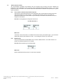


![[2012-2014], organisé par PHARE (Université Paris 1)](http://vs1.manualzilla.com/store/data/006462034_1-2753b561fa6466b7e65de41c27ae6de0-150x150.png)