1
P&T CP/M® 2 USER'S MANUAL
Radio Shack Hard Disk Addendum
P&TCPIM®2
for the
TRS-BO Models II, 12, and 16
User's Manual
Radio Shack Hard Disk AddendUDl
TriSoft
1825 E. 38~ St., Suite 202
Published by
Copyright
©
Austin, Texas 78722
(512) 472-0744
1983 Pickles & Trout
All rights reserved. No part of this publication may be reproduced, transmitted, transcribed, stored
in a retrieval system, or translated into any language, in any form or by any means, electronic,
magnetic, optical, chemk.1l, manual, or otherwise, without the prior written permission of the
publisher. Printed in the United States of America.
10 9 8 7 6
Pickles & Trout is a registered trademark of Pickles & Trout
CP/M is a registered trademark of Digital Research, Inc;
MAC is a trademark of Digital Research, Inc.
TRS-SO and TRSDOS are trademarks of Tandy Corp.
Z-80 is a trademark of Zilog, Inc.
IMPORTANT NOTE
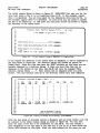
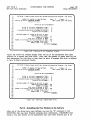
You should have received P&T CP/M 2 on a diskette with a label like the one shown below. If you did
not receive such a diskette, you may not have received a valid copy of the system. Please contact
Pickles & Trout at once. All P&T CP/M 2 labels are printed in green ink on white paper.
If you purchased a registered user's copy ofP&T CP/M 2 you are required to transfer the registration
to your name. There is a fee for this transfer. If you fail to transfer the registration you will not
receive the Pickles & Trout newsletter, will n~t be eligible for updates to the system, and will not be
able to receive assistance from Pickles & Trout.
P.O. Box 1206
'3oleta, CA 93116
~
All software on this dis
ther in
source or object ffcor:m~,i:S~~~~~:. and
may be uaed anQ.
r the
terms of
re LiI
tte is serial~~.~~~~t'.F~bythereoistered
h 't or
software on it may
19a.9UJllrKJuted, resold, or transferred withthe written consent of Pickles & Trout.
DISCLAIMER
The publisher has made a reasonable effort to insure that the computer programs described herein
are correct and operate properly and that the information presented in this publication is accurate;
however they are sold and licensed without warranties either expressed or implied, including, but not
limited to, the implied warranties of merchantibility and fitness for a particular purpose. The
publisher is not liable for consequential damages resulting from the use of this product either
individually or in concert with other computer programs. Further, the publisher reserves the right to
revise this publication and the programs described herein and to make changes from time to time in
the contents thereof without obligation of the publisher to notify any person or organization of such
revision or changes.
TABLE OF CONTENTS
1. INTRODUCTION
Introduction ..........................................................
Files on the Diskette . . . . . . . . . . . . . . . . . . . . . . . . . . . . . . . . . . . . . . . . . . . . . . . . . .
1.1
1.1
2. NOTATION
Conventions of Notation
.. . .. . ... .. .. . . .. .. .. . .. .. . .. . .. . .. . ... ... .. . ..
2.1
Getting Started ....................................... . . . . . . . . . . . . . . . .
3.1
3. GETIING STARTED
4. DIFFERENCES FROM THE FLOPPY VERSION
Differences From the Floppy Version
4.1
5. LIMITING DRIVE ACCESS
Limiting Drive Access .................................................
5.1
6. UTILITY PROGRAMS
Introduction ..........................................................
ACCESS .............................................................
BFBACKUP ......... . . . . . . . . . . . . . . . . . . . . . . . . . . . . . . . . . . . . . . . . . . . . . . . . .
BFRESTOR . . . . . . . . . . . . . . . . . . . . . . . . . . . . . . . . . . . . . . . . . . . . . . . . . . . . . . . . . .
BKMOUNT . . . . . . . . . . . . . . . . . . . . . . . . . . . . . . . . . . . . . . . . . . . . . . . . . . . . . . . . . .
CLEARDIR . . . . . . . . . . . . . . . . . . . . . . . . . . . . . . . . . . . . . . . . . . . . . . . . . . . . . . . . . .
FILEBACK . . . . . . . . . . . . . . . . . . . . . . . . . . . . . . . . . . . . . . . . . . . . . . . . . . . . . . . . . .
HDCHECK . . . . . . . . . . . . . . . . . . . . . . . . . . . . . . . . . . . . . . . . . . . . . . . . . . . . . . . . . .
HDCONFIG ... . . . . . . . . . . . . . . . . . . . . . . . . . . . . . . . . . . . . . . . . . . . . . . . . . . . . . . .
HFORMAT .......... . . . . . . . . . . . . . . . . . . . . . . . . . . . . . . . . . . . . . . . . . . . . . . . . .
6.1
6.2
6.6
6.14
6.24
6.25
6.27
6.32
6.37
6.38
7. CONFIGURING THE SYSTEM
Introduction . . .. . . . . .. . .. . .. . .. . .. . .. . . . . . . . . . . . . . .. . .. . .. . . . . .. . .. . . .
'!erms and Concepts ................................... . . . . . . . . . . . . . . . .
1'radeoffs . . . . . . . . . . . . . . . . . . . . . . . . . . . . . . . . . . . . . . . . . . . . . . . . . . . . . . . . . . . . .
Single Diskette Drive Systems . . . . . . . . . . . . . . . . . . . . . . . . . . . . . . . . . . . . . . . . .
Getting Ready ...................................... '. . . . . . . . . . . . . . . . . .
Using HDCONFIG ....................................................
Possible Error Messages ............... '. . . . . . . . . . . . . . . . . . . . . . . . . . . . . . . .
7.1
7.2
7.3
7.6
7.6
7.12
7.28
8. ERROR MESSAGES
System Error Messages
APPENDIX A
INDEX
8.1
P&T CP/M '2
RS Hard Disk Addendum
INTRODUCTION
page L1
1.1 Introduction
The Radio Shack Hard Disk version of P&T CP/M 2 fully supports the use of the
Radio Shack 8.7 and 12 Mbyte hard disk systems for mass storage on the TRS-80
Models n, 12 and 16 Microcomputers. Up to 4 hard disk drives may be connected to
a computer giving a total of 34.8 or 48 Mbytes of on-line storage.
P&T CP/M 2 allows you complete flexibility in assigning the hard disk storage so
that you may tailor the system to your needs. You may assign multiple logical
drives to each physical hard disk drive with the limitation that each logical drive
may be no larger than 8192 Kbytes (8,388,608 bytes) which is the maximum logical
drive size supported by CP/M 2.
This supplement to the the P&T CP/M 2 User's Manual is designed to provide you
with the additional information necessary to use P&T CP/M 2 with a Radio Shack
Hard Disk system.
The hard disk version of P&T CP/M 2 is completely compatible with the floppy disk
version. Most programs will not need any changes at all in order to run with the
hard disk system.
If you desire assistance from Pickles & Trout it is absolutely necessary that your
copy of P&T CP/M 2 be registered. To register your copy you must fill out and
return the registration cards you received with the original diskette. If you did not
receive the cards, please call Pickles & Trout at once for instructions on how to
register your copy.
Please have your system serial number available when you contact Pickles & Trout
regarding your copy of P&T CP/M 2; YOU WILL BE ASKED FOR IT. The serial
number appears on the label of the master diskette, on the front of this manual,
and is displayed on the console every time the system is reset.
Please realize that we must limit assistance with P&T CP/M 2 to matters concerning
the operating system and its supporting utility programs. We would like to help
everyone with their programming problems but it is impossible to do so. We will try
to help you as much as we can but please do not expect us to give you
step-by-step instructions on how to customize a specific software package. In such
a case all we can do is give you some general direction and refer you to the
appropria te parts of this addendum.
1.2 Files on the Diskette
You should find the following files on your master diskette in addition to the files
described in the P&T CP/M 2 User's ManuaL If you are upgrading from another
version of P&T CP/M 2 you should find these files (and others for actually installing
the upgrad~) on the diskette you received.
ACCESS.COM
P&T utility program to allow you to alter the access mode of
logical drives assigned to a hard disk from the console. See
Section 6.2 of this addendum for further information.
page L2
Files on the Diskette
INTRODUCTION
P&T CP/M 2
RS Hard Disk Addendum
BFBACKUP.COM
P&T utility program for backing up a disk file which is larger
than the capacity of a diskette onto multiple diskettes. See
Section 6.3 of this addendum for further information.
BFRESTOR.COM
P&T utility program for restoring a disk file backed up by
BFBACKUP. See Section 6.4 of this addendum for further
inf orma tion.
BKMOUNT.COM
P&T utility program that is used in conjunction with the
FILE BACK utility program. Typically this program would not be
used independently of FILEBACK. See Section 6.5 of this
addendum for further information.
CLEARDIR.COM
P&T utility program that completely clears the directory area of
a logical drive assigned to a hard disk. This utility should be
used with care since its action is irreversible. See Section 6.6 of
this addendum for further information.
FILEBACK.COM
P&T utility program that backs up all files that are smaller than
the capacity of a diskette from a logical drive on a hard disk to
multiple diskettes. This program reads the directory of a hard
disk and generates a series of SUB files to be used with SUBMIT.
The SUB files make use of the PIP utility to perform the file
transf ers. The user is prompted to change diskettes when
necessary during the backup process. The principle limitation of
this backup technique is that logical drive A cannot be specified
as the destination drive. See Section 6.7 of this addendum for
further information.
HDCHECK.COM
P&T utility program to check the portion of a hard disk which is
assigned to a logical drive for flawed sectors. If any flawed
sectors are found, they are blocked from usage. This program
does not. affect the information stored on the logical drive so it
may be run periodically to insure the integrity of the drive. See
Section 6.8 of this addendum for further information.
HDCONFIG.COM
P&T utility program to configure the disk storage on the system.
This program allows you complete freedom in assigning logical
drives on the system so that you can tailor the system to your
needs. See Chapter 6.9 of this addendum for further information.
HFORMAT.COM
P&T utility program to format a hard disk drive. This program
allows you to format some or all of a hard disk drive. The
portion to be formatted may be specified either as a range of
tracks or by giving the letter of a logical drive assigned to a
hard disk. In the latter case, all of the tracks assigned to the
logical drive will be formatted. In addition to formatting, this
program also allows you to install a bootstrap program on the
hard disk 0 (the primary unit). This program automatically loads
the system from a working system diskette when power is applied;
you will no longer need to hold the <break> and <repeat> keys
while booting. See Section 6.10 of this addendum for further
inf orma tion.·
P&T CP/M 2
RS Hard Disk Addendum
NOTATION
page 2.1
Conventions of Notation
2.1 Conventions of Notation
In general, this addendum uses the same notation as the P&T CP/M 2 User's Manual
for P&T CP/M 2.2m. For your convenience, an explanation is included here.
For ease of reference, all page numbers in this manual consist of two numbers.
The first refers to the chapter number and the second to the page number within
the chapter.
Figures within this manual are numbered in a similar way, but the second number
denotes the figure, not the page, within the chapter. For example, Figure 5.8 refers
to the eighth figure in the fifth chapter. If it is necessary to indicate a specific
line within a figure, a hyphen separates the figure and line numbers (e.g. Line 5.8-12
means line 12 of Figure 5.8). Keep in mind that "Line _" refers to a line of a
figure, not a line of the text.
When numbers are used within the addendum, they should be considered to be
decimal (base 10) unless otherwise noted. A hexadecimal number (base 16) is
. indicated by appending the letter "h" to the number (e.g. lAh). A binary number
(base 2) is indicated by appending the letter "b" to the number (e.g. 101b). In
figures that represent console displays, this convention will not be used if the
program that generated the display does not follow it. Every effort has been made
to make t.he figures representing console displays as accurate as possible. The text
relating to a figure will specify the base of the. numbers displayed if it is not
obvious from the context.
In this addendum, the term "Kbyte" (or Kb) is taken to refer to 1024 bytes. The
term "Mbyte" (or Mb) is used to refer to 1024 Kbytes (ie. 1,048,576 bytes).
When it is necessary to refer to one of the named keys on the keyboard, the name
of the key is enclosed in angle brackets. For example, <enter> refers to the key on
the keyboard labeled "ENTER". If you are instructed to type <enter> at some point,
it is expected that you will press the key labeled "ENTER" rather than typing the 7
characters "<", "e", "n", "t", "e", "r", ''>''.
Control keys and control codes are denoted by the characters "CU-" followed by a
letter and enclosed in angle brackets (e.g. <ctl-A». In other manuals, control codes
are often indicated by a caret or up-arrow immediately preceding the letter (e.g.
"A). The distinction between control keys and control codes is a fine one. This
addendum will use the term "control key" to refer to the key that is actually typed
to generate a control code. For example, to generate a <c tl-A> , you would type
the "A" key on the keyboard while holding down the <ctrD key; the <ctrD key
functions as a special type of shift key.
The control code is the numeric code that is generated by the keyboard and sent to
the computer when a control key is typed. Control codes are sometimes called
control characters. Keep in mind that the term "control code" may be used without
a reference to the keyboard. For example, some programs may use control codes to
perform certain functions, such as manipulating the console display. In this case,
the codes are generated by the program and the keyboard is not involved.
Many figures show a dialog between the computer and the user. This technique is
used heavily when explaining how to use various utility programs. In these dialogs,
page 2.2
Conventions of Notation
NOTATION
. P&T CP/M 2
RS Hard Disk Addendum
characters displayed on the console by the computer are shown in plain text;
characters typed in by the user are shown underlined.
In this addendum, both the terms "diskette" and "disk" are used. "Diskette" refers
only to a floppy diskette. An example would be the diskette you originally
received. The term "disk" has a general meaning. It can refer to a diskette or to
a hard disk.
In this addendum the term "CP/M" is used in referring to general features and
capabilities of the CP/M operating system. The term "P&T CP/M 2" refers
specifically to the Pickles & Trout adaptation of the CP/M operating system for the
TRS-80 Model n/12/16.
It is frequently desirable to distinguish between physical and logical disk drives.
A
physical drive refers to the actual hardware of a disk drive. Examples of physical
drives are diskette drives and hard disk units. CP/M refers to disk storage in terms
of logical drives, denoted by the letters A through P.
There is not always a 1-t0-1 correspondence between logical and physical drives
since several logical drive can be assigned to a single hard disk or diskette drive.
In P&T CP/M 2 a logical drive never includes more than one physical drive. The
physical diskette drives are referred to by numbers from 0 to 3. Physical diskette
drive 0 is the built-in drive on a Model n and the left hand built-in drive on a
Model 16 or 12. There is always a physical diskette drive 0 on the system. Physical
diskette drive 1 is the first expansion drive on a Model n system and the right hand
built-in drive on a Model 16 or 12. Physical diskette drives 2 and 3 are the
remaining expansion drives.
The physical hard disk drives are also referred to by numbers from 0 to 3. Physical
hard disk drive 0 is the primary hard disk unit, physical hard disk drive 1 is the
first secondary hard disk unit, etc.
Pc5cT CP/M 2
RS Hard; Disk Addendum
GETTING STARTED
page 3.1
3.1 Getting Started
If you have purchased an upgrade of your copy of P&T CP/M 2, follow the
instructions packaged with the diskette for installing the new modules in your
module library. If you purchased P&T CP/M 2 as a Radios Shack hard disk system,
these modules are already in the library.
Before beginning to use P&T CP/M 2 you should make a working system diskette.
See Chapter 3 of the P&T CP/M 2 User's Manual for instructions. The first working
system diskette you generate will include drivers for only the floppy drives on your
system. In order to access the hard disk drives on your system you must use the
MODSEL (see Chapter 6 of the P&T CP/M 2 User's Manual) utility program to
include in the system the necessary modules.
While it is executing, MODSEL will present you with the names of any "Hard Disk
Driver Modules" that are available for you to use. You should choose a Radio
Shack hard disk driver module (the standard one is named RSHl). If there are no
. Radio Shack hard disk modules listed, either you do not have a hard disk version of
the system or, if you are upgrading, you have not installed the new modules in your
module library.
MODSEL will also ask you to choose a "Disk Table Module". It is this module that
actually defines how the disk drives on your system are used. We have supplied
with the system a number of these modules for typical disk configurations. Refer
to appendix A of this addendum for a description of these modules. If one of the
supplied modules provides a configuration that meets your need you need merely
select it.
If none of the supplied disk table modules seems to be quite right, you can create
your own using the HDCONFIG utility program. Chapter 7 of this addendum
discusses in detail the considerations you should be aware of before creating your
own disk table module. You should read 'Chapter 7 carefully before custom
configuring your system.
After you have used MODSEL to select the hard disk related modules (and any
other modules you wish to include in the system) the procedure for generating a
working system diskette is exactly the same as for a floppy only system. See the
P&T CP/M 2 User's Manual for details.
page 3.2
GETTING STARTED
NOTES
P&T CP/M 2
RS Hard Disk Addendum
P&'I' CP1M 2
DIFFERENCES FROM THE FLOPPY VERSION
RS Hard· Disk Addendum
page 4J.
4.1 Differences From the Floppy Version
The Radio Shack Hard Disk version of P&'I' CP1M 2 is very similar to the standard
floppy version. Virtually all programs that run with the floppy version will also run
with the Radio Shack Hard Disk version. There are a few minor differences which
are described below.
L
With the Radio Shack Hard Disk system, it is not necessary to have a system
diskette mounted on physical diskette drive 0 to perform a warm boot (as is
the case for a Model II or 16). In fact, a warm boot does not require any
diskette to be mounted. The working system diskette is needed only for the
cold boot process (power on boot or RESET). Because of this you may switch
diskettes (even of differing densities) on physical diskette drive 0 any time you
are at the command level of P&'I' CP 1M 2. All you need to do is press the
<break> key after you change diskettes.
2.
The Radio Shack Hard Disk system allows you complete freedom in assigning
logical drives. For example, you may have logical drives A, B, and C assigned
to the hard disk and logical drives D and E assigned to diskette drives. This
may lead to confusion in some of the diskette oriented utility programs
(FORMAT, DISKTEST, etc.) when you are asked to specify the diskette disk
drive on which some operation is to take place.
In order to alleviate the confusion, all of these utility programs allow you to
specify diskette drives by either the logical drive letter assigned to the drive
or the physical drive number. For a Model n the built-in drive is physical
drive 0 and the expansion drives are physical drives 1 through 3. For a Model
12 or 16, the two built in drives are physical drives 0 and 1 while the
expansion drives are physical drives 2 and 3.
3.
Several new utility programs oriented toward the hard disk have been added to
the system. These programs have to do with formatting and testing the hard
disk, configuring the system, and backing up and restoring data on the hard
disk. These programs are described in Chapter 6 of this addendum.
4.
A new system feature has been added that allows you to limit access to any
logical drives assigned to a hard disk. This feature allows you to write
protect individual logical drives on a hard disk without write protecting the
entire disk. This feature can also be used to implement a password scheme
for gaining access to logical drives on the hard disk. The access limitation
function of the system is described in Chapter 5. The ACCESS utility program,
described in Section 6.2, provides a means of modifying the drive access from
the console.
5.
The system MENU function DP cannot set the number of floppy drives on a
hard disk system. The number of drives is determined by the drive parameter
table module that is selected for inclusion in the system (see Chapter 3). You
may create your own drive parameter table modules using the HDCONFIG
program as described in Chapter 7.
page 4.2
DIFFERENCES FROM THE FLOPPY VERSION
P&T CP/M 2
RS Hard Disk Addendum
NOTES·
LIMITIN G DRIVE ACCESS
P&T CP/M 2
RS Hard Disk Addendum
page 5J.
5.1 Limiting Drive Access
The Radio Shack Hard Disk version of P&T CP/M 2 includes a method of limiting
access to the logical drives that are assigned to the hard disk. There are two
forms of access limitation available: access to the drive can be completely denied
or access can be limited to reading only.
The type of access to a drive may be modified by a program using Special System
Functions 27 and 28 (see Chapter 16 of the P&T CP/M 2 User's Manual). In addition,
the system configuration program, HDCONFIG, allows you to specify the type of
access to be permitted to each logical drive when the system is cold booted. See
Chapter 7 of this addendum for details of configuring the system with the
HDCONFIG utility program.
The utility program ACCESS provides a way to change the type of access to a
logical drive on a hard disk interactively from the system console. See Section 6.2
of this addendum for information on using ACCESS.
The ability to completely deny access to a logical drive can be used to provide
regulated access to a disk drive. For example, suppose the system is configured
with 4 logical drives assigned to a hard disk. Each of these 4 drives might be used
for different types of programs. Bookkeeping programs could be on one of the
drives, customer records on another, inventory management on a third, and program
development on the fourth. The system could be configured so that all of these
logical drives are ,",ot accessible when the system first comes up; the user would be
initially limited to using the diskette drives.
A program could then be written that would allow a user to change the status of
one or more of the logical drives so that it becomes accessible. This program could
include some sort of security measures such as requiring passwords or other
identification before allowing access to a logical drive. Note that passwords and
other security measures are not part of the system; they are implemented by a
program of some sort. It is possible for anyone with a knowledge of the system ·to
write a program (or use the ACCESS utility program) to gain access to any logical
drive to which access is blocked hence this scheme cannot be considered to provide
high level security.
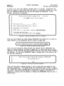
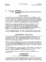
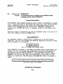
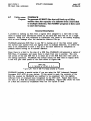
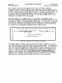
If a user or a program attempts to gain access to a logical drive to which access
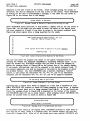
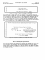
is denied, the error message given in Figure 5J. will be given. The "xx" in the
message will be replaced by a hexadecimal representation (OO=A, 01=B,...OF=P) of the
logical drive to which access was attempted. You may use the ERROR program to
get an explanation of the error code if you wish. The most typical result of this
error is that any running program will abort and the user will be retumed to the
system command level.
(
Hard disk lock out error, code .. HLxx ).
Figure 5.2 Error Message for Drive Access Violation
NOTE: Logical drive A must be accessible when the system is cold booted. If
logical drive A is not made accessibl~, the system will not run because the first
thing it does after a cold boot is to try to log onto logical drive A. Logical drive
A may be made initially read/only, however.
page 5.2
LIMITIN G DRIVE ACCESS
P&T CP/M 2
RS Hard Disk Addendum
Access to a logical drive on a hard disk can also be limited to reading only. This
feature of the system can be used to write protect individual logical drives on a
hard disk without write protecting the entire drive. This feature can be
particularly useful while doing program development. The logical drives that should
not be written to by the program can be set to read only status so that any
attempt by the program to write to the drive will be trapped and an error message
given.
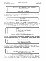
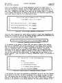
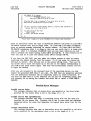
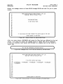
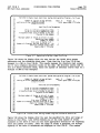
The error message indicating that a drive is write protected can be caused by two
conditions. If an entire disk drive is write protected by means of the write protect
switch on its front panel, any attempt to write to a logical drive on that disk will
result in the error message shown in Figure 5.2.
~
H8rd disk
wrl~e prot error,
code • HPOI
Figure 5.2 Error Mess8ge for H8rdware
~
Wrl~e Protec~
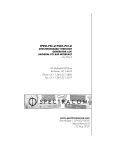
If a logical drive is set for read/only access, any attempt to write to that drive
will result in the error message shown in Figure 5.3. The most typical result of
either write protect error message is that any program that is running will be
aborted and the user will be returned to the system command leveL
(
H8rd disk wr Ite prot error, code = HPOO )
Figure 5.3 Error Mess8ge for Software
Wrl~e
Protect
P&T CP/M 2
RS Hard Disk Addendum
UTILITY PROGRAMS
page 6.1
Introduction
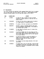
6.1 Introduction
This section describes the additional utility programs (listed below) that are supplied
wi th the Radio Shack Hard Disk version of P&T CP/M 2. These programs provide
addi tional functions needed to use the hard disk version of P&T CP 1M 2.
program name
purpose
6.2
ACCESS
To allow the user to change the type of access
permitted to logical drives on a hard disk from the
system console.
6.6
BFBACKUP
To back up a file which is larger than the capacity
of a single diskette to multiple diskettes.
6.14
BFRESTOR
To restore a file that was backed up by BFBACKUP.
6.24
BKMOUNT
Provides a means of changing diskettes when used
with the FILEBACK utility program. This program is
not normally used by itself.
6.25
CLEARDIR
To wipe clean the directory area of a logical drive
on a hard disk.
6.27
FILEBACK
To generate SUBMIT files that will backup all files
from a given logical drive to multiple diskettes. Note
that all files must be smaller than the total capacity
of an empty diskette.
6.32
HDCHECK
To check the section of a hard disk assigned to a
logical drive for flawed sectors. If any flawed
sectors are found, they are locked out from
subsequent usage.
6.37
HDCONFIG
To configure the disk storage allocation of the hard
disk system.
6.38
HFORMAT
To format some or all of a hard disk. Also can write
a bootstrap to hard disk 0 (the primary drive) so that
P&T CP/M 2 will boot up immediately (without holding
<break> and <repeat».
page 6.2
ACCESS
6.2
UTILITY PROGRAMS
P&T CP/M 2
RS Hard Disk Addendum
Utility name: ACCESS
Purpose: To allow the user to change the access mode of a logical
drive defined on a hard disk from the console.
General Description
The ACCESS utility program allows the user to change the access mode of logical
drives assigned to a hard disk from the console. ACCESS has two modes of
operation, the interactive mode and the command line mode.
In the interactive mode, ACCESS displays the current access mode of each logical
drive defined for the system and allows you to make changes at will. The logical
drives that are assigned to diskette drives are also displayed even though there is
no access control for them.
In the command line mode, all information about changing the access mode of
various drives is given on the command line that executes ACCESS. ACCESS reads
this information and makes the appropriate changes, reporting each change on the
cohSole as it is·· made~
. -.
Note that the changes made by ACCESS remain in effect only until they are
changed by using ACCESS again or until a cold boot (RESET) occurs. The access
mode for various drives can also be changed by other programs using the Special
System Functions provided for that purpose. If you want the system to cold boot
with a particular access modes in effect, you must use the HDCONFIG utility
program to reconfigure the system to that configuration.
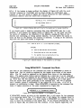
Using ACCESS - Interactive Mode
At any time while ACCESS is running you may press the <break> key to return to
the operating system. If you press the <break> key, ACCESS will ask you if you
really want to quit. If you respond affirmatively, you will be returned to the
system. If you respond negatively, you will be returned to the place at which you
pressed <break>.
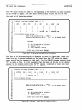
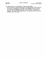
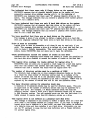
Figure 6.1 shows the command line for executing ACCESS in the prompted mode.
A>ACCESS<enter>
Figure 6.1
Command Line for Executing ACCESS in Prompted Mode
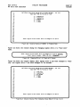
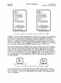
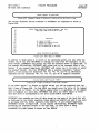
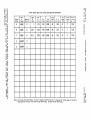
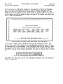
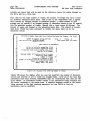
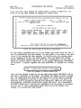
Figure 6.2 shows the basic display of ACCESS. Lines 6.2-4 to 6.2-19 report the
current access mode of each logical drive on the system. Note that diskette drives
are also reported even though there is no access control for them. On Line 6.2-22
you are asked to enter the logical drive letter for a drive whose access mode you
want to change or "0" if you want to return to the operating system.
P&T CP/M 2
UTILITY PROGRAMS
BS Hard Disk Addendum
1:
2:
3:
page 6.3
ACCESS
P&T CP/M 2 Hard Disk System Drive Access Manager - ver l.xx
Copyright 1982 by Pickles & Trout
4:
5:
ABCDE-
6:
7:
8:
9:
read/write
read/write
read/write
floppy
floppy
10:
11:
12:
13:
14:
15:
16:
17:
18:
19:
20:
21 :
22:
23:
24:
Enter logical drive letter (A-P) to change (0 to quit):
Figure 6.2
Console Display of ACCESS In Prompted Mode
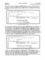
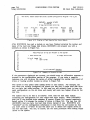
Figure 6.3 shows the console dialog for changing logical drive A to "read only"
mode.
Enter logical drive letter (A-P) to change (0 to quit): A<enter>
Enter type of access ( NONE, RO, RW ): RO<enter>
Figure 6.3 Changing Drive A to "read only" Access
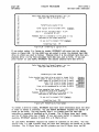
Figure 6.4 shows the console display after logical drive A has been changed to "read
only" and logical drive C has been changed to "no access".
~
1
2
3
P&T CP/M 2 Hard Disk System Drive Access Manager - ver l.xx
Copyright 1982 by Pickles & Trout
4
ABCDE-
5
6
7
8
9
read only
read/write
no access
floppy
floppy
10
11
12
13
14
15
16
17
18
19
20
21
22
23
24
Enter logical drive letter (A-P) to change (0 to quit):
Figure 6.4
Console Display After Changing Access Mode of Drives A and C
page 6.4
ACCESS
UTILITY PROGRAMS
P&T CP/M 2
RS Hard Disk Addendum
Using ACCESS - Command Line Mode
ACCESS also has a command line mode that allows you to change the access mode
of several drives with one command line. This mode also allows SUBMIT files to
change drive access modes if necessary. When using the command line mode, you
specify the drives to be changed by typing the drive letter followed by an equals
sign followed by one of three access modes (RO, RW, or NONE). For example the
string "B=NONE" will set logical drive B to "no access". Similarly, "B=RO" will set
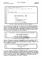
logical drive B to "read only". Figure 6.5 shows an example of using the command
line mode of ACCESS.
A>ACCESS AeRO
logical drive
logical drive
logical drive
BeRO C-RW<enter>
A set to read only
B set to read only
C set to read/write
A>
Figure 6.5
Executing ACCESS In the Command Line Mode
As shown in Figure 6.5, ACCESS reports each change in drive access mode as it is
made. This assures you that ACCESS actually made the changes you wanted. If a
change you wanted made is not reported, either ACCESS could not understand the
command line you typed or you asked for an illegal operation. Examples of illegal
operations are specifying a logical drive that is not defined for the system,
specifying a logical drive assigned to a diskette drive, or trying to set logical drive
A to "no access".
Other examples of command lines that could be used with ACCESS are:
ACCESS E=NONE
Makes logical drive inaccessible.
ACCESS B=RO D=RW F=RW
Makes logical drive B accessible for reading only and logical drives D and F
accessible for both reading and writing.
Possible Error Messages
Not a valid response, please re-enter
This message is displayed either alone or with other messages if the response
you give to a question is not among the acceptable responses. Frequently the
question asked will indicate what responses are considered acceptable. An
example of a case where this message would be given is entering "Q" when
prompted for a logical drive letter.
Please respond with A-P or 0 only
This message indicates that you did not enter one of the acceptable responses to
the request for a logical drive letter.
That logical drive is not on the system
This message is displayed if you enter the letter of a logical drive that is not
defined for the system. The drives that are defined are displayed on the
console by ACCESS.
P&T CP/M 2
RS Hard Disk Addendum
UTILITY PROGRAMS
page 6.5
ACCESS
There is no access control for diskette drives
This message indicates that you are trying to change the access mode of a
diskette drive. The system does not support access control for diskette drives.
Logical drive A must always be accessible
This message indicates that you have tried to set logical drive A to "no access".
The system requires logical drive A to always be accessible in order to function.
Logical drive A may be set to either "read only" or "read/write", however.
Please respond with nNONER, RRon or nRwn only
This message is displayed if the response you made to the query for the type of
access for a logical drive could not be understood by ACCESS. Use only the
responses listed
You may not make the current drive inaccessible
ACCESS will return to the command mode of the system with the current drive
unchanged. If drive B was the current drive when you executed ACCESS, it will
still be the current drive when ACCESS is finished. Since the system must
al ways have access to the current drive, ACCESS does not allow you to set the
current drive to "no access". You may, however, set the current drive to "read
only" access.
UTILITY PROGRAMS
page 6.6
BFBACKUP
6.3
P&T CP/M 2
RS Hard Disk Addendum
Utility name: BFBACKUP
Purpose: To back up a file that is larger than the capacity of a
diskette to multiple diskettes.
General Description
Normal file transfer programs like PIP and FASTCOPY will work only when there is
sufficient space on the destination drive for the entire file being transferred.
BFBACKUP provides a means of backing up a large file to multiple diskettes.
Sequence information is transferred along with the file to insure that the file is
properly restored (by BFRESTOR). BFBACKUP will optionally perform a read back
verification of the data after it is written to the diskette to insure data integrity.
BFBACKUP has two modes of operation. In the interactive mode, BFBACKUP
prompts for all information regarding source and destination drives and file names.
In the command line mode the source and destination drives, the file name, and
whether or not to verify the output files are specified on the command line that
executes BFBACKUP. The command line option allows you to set up SUBMIT files
that automatically initiate the backup of a certain file.
BFBACKUP is intended only for backing up large files. It should not be used if the
entire file will fit" on a single diskette. The parts of the backed up file that are
stored on the diskettes will typically not be of use individually. It is necessary to
use BFRESTOR to recreate a copy of the original file before it can be used.
Using BFBACKUP - Interactive Mode
At any time while BFBACKUP is running you may press the <break> key to return to
the operating system. After you press <break>, BFBACKUP will ask you if you
really wanted to quit. If you respond affirmatively, you will be returned to the
command level of the system. If you respond negatively, you will be returned to
the point at which you pressed <break>.
Similarly you may press the <FD key to start over at the beginning of BFBACKUP.
After you press <FD, BFBACKUP will ask you if you really want to start over. If
you respond affirmatively, BFBACKUP will start over just as if you had re-executed
it. If you respond negatively, BFBACKUP will return you to the point at which you
pressed <FD.
Any time BFBACKUP asks a question requiring a "yes/no" answer, it will accept "Y",
"y", "T", "t", and "1" as affirmative responses. "N", "n", "F", tift', and "0" will be
accepted as negative responses. All other responses are not valid.
Figure 6.6 shows the command line that will execute BFBACKUP in the prompted
mode.
A>BFBACKUP<enter>
Figure 6.6
Command Line to Execute BFBACKUP In Prompted Mode
UTILITY PROGRAMS
P&T CP/M 2
page 6.7
BFBACKUP
RS Hard Disk Addendum
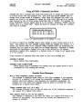
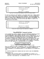
The initial console dialog is shown in Figure 6.7. BFBACKUP first asks you for the
drive from which a file is to be transferred (Line 6.7-9). In this example, logical
drive C is specified You are then asked for the destination drive (Line 6.7-11). In
this example, logical drive D is specified On Line 6.7-15, you are asked to specify
the file to be backed up. At this point you may press <ctl-D> (as shown) to display
the directory of the source drive.
Pickles &Trout
1:
2:
3:
4:
5:
Big-Fi Ie
Backup Utility
-
ver l.xxx
( Hit <BREAK> to quit, <Fl> to restart)
6:
7:
8:
9:
10:
Enter Source drive • • • • • • • • • (A-P): C<enter>
11:
Enter floppy-disk Destination drive
12:
13:
14:
15:
16:
Enter name of file to back up
- or Press CTRL-D to view Source directory: <ctl-D>
Figure 6.7
(A-P): D<enter>
Initial Console Dialog of BFBACKUP In Prompted Mode
If you request the directory of the source drive be displayed, it will be displayed in
the form shown in Figure 6.8. The directory listing will include all system (or
hidden files). These are files that have the "SYS" attribute set and hence are not
normally displayed in a directory listing. If there are more files than can be
displayed on the console at one time, Line 6.8-22 will have the message "More
directory entries follow •..•". More entries will be displayed after you press
<enter>. This will continue until all of the directory entries have been displayed.
1:
2:
3:
4:
5:
6:
7:
8:
9:
10:
11:
12:
13:
14:
15:
16:
17:
18:
19:
20:
21 :
22:
23:
Directory (Including "hidden" files)
C:
C:
C:
C:
C:
C:
C:
C:
C:
C:
C:
C:
C:
C:
C:
ASM
DUMP
COM
COM
CRT
ED
XSUB
DDCHECK
COM
COM
DATIME
COM
BIGFILE EXT
DEF
COM
.
DDT
COM
.
AUTOEXEC COM
DUtJP
ASM
.
CLEARDIR COM
End of directory listing
(press <enter> to continue)
Figure 6.8
~
Display of Source Disk Directory from BFBACKUP
After the last group of directory entries is displayed and you press <enter>, you will
be returned to the initial console dialog as shown in Figure 6.9. You may then
enter the name of the file to be transferred on Line 6.9-15. You may include a
drive designation in the file name if you wish but, if you do so, it must match the
source drive entered on Line 6.9-9. After you have entered the file name you will
UTILITY PROGRAMS
page 6.8
BFBACKUP
P&:T CP/M 2
RS Hard Disk Addendum
be asked if you want each diskette verified after it is written. Verification will
cause the backup to take about twice the time of a nonverified backup but it will
give you maximum assurance that the file was backed up accurately. In the
example, verification is requested.
1:
2:
3:
4:
5:
Pickles & Trout
Big-Fl Ie
Backup Utility
-
ver l.xxx
( Hit <BREAK> to quit, <F1> to restart)
6:
7:
8:
9:
10:
11:
12:
13:
14:
15:
16:
17:
18:
Enter Source drive • • • • • • • • • (A-P): C
Enter floppy-disk Destination drive
Enter name of fl Ie to back up
- or Press CTRl-D to view Source
(A-P): D
directory: BIGFllE.EXT<enter>
Do you want each disk to be
verified after having been written? (YIN): Y<enter>
19:
Figure 6.9
Entering the Name of the File to Backup
Once you have finished the initial dialog, BFBACKUP will prompt you to mount an
empty diskette on the destination drive as shown in Figure 6.10.
Insert a fresh disk In drive
Figure 6.10
D and press <ENTER>: <enter>
Prompt for Mounting a New Diskette
Once you have mounted an empty diskette and pressed <enter>, BFBACKUP will
begin the backup operation as shown in Figure 6.1L It first shows you how many
diskettes you will need for the entire backup (Line 6.11-1) and then starts writing to
the diskette. On Line 6.11-6 BFBACKUP keeps a running tally of how much of the
file has been backed up.
1:
Note:
You will need 3 floppy disks to back-up C:BIGFllE.EXT
2:
3:
4:
Writing backup disk #
5:
105 K
6:
Figure 6.11
Writing to the First Diskette
After the first disk is entirely written, it will be read back and verified if you
requested verification. The display during the verification pass is shown in Figure
6.12. BFBACKUP keeps a running tally of how much of the file has been verified on
Line 6.12-5. After the entire diskette is verified the message on Line 6.12-7 is
displayed to indicate that the diskette is finished and BFBACKUP waits for you to
press <enter>.
UTILITY PROGRAMS
P&T CP/M 2
page 6.9
BFBACKUP
RS Hard Disk Addendum
1:
2:
3:
Note:
You will need 3 floppy disks to back-up C:BIGFILE.EXT
Verifying backup disk I 1
4:
5:
594 K
6:
7:
Backup disk I 1 Is completed.
Figure 6.12
Verifying the Data' Written to the First Diskette
If, while making the verification pass, BFBACKUP detects an error, it will display
the message shown in Figure 6.13.
*** VER I FY ERROR ***
(press <enter> to continue)
Figure 6.13
Reporting a Verify Error
After you press <enter> in response to the message of Figure 6.13, BFBACKUP
presents you with the options shown in Figure 6.14. You may retry writing the file
on the same diskette or you may try another diskette. If you retry the same
diskette, BFBACKUP will return to the display of Figure 6.1L If you elect to try
another diskette, BFBACKUP will return to the display of Figure 6.10.
OPTIONS:
1:
2:
3:
R - Retry disk now on Destination drive
4:
5:
6:
7:
T - Try another disk
Enter your choice here:
Figure 6.14 Prompting for Action to Take for a Verify Error
After the successful completion of a diskette, BFBACKUP will display the message
shown in Figure 6.15 and wait for you to mount another diskette and press <enter>.
Remove disk from drive D.
1:
2:
3:
Insert a fresh disk in It's place.
4:
5:
Press <ENTER> when ready:
Figure 6.15
~
Prompting for Another Diskette
If you do not change diskettes as requested in Figure 6.15 or if you should
accidentally mount a diskette that had already been used in the backup operation,
BFBACKUP will display the message shown in Figure 6.16.
1:
2:
3:
4:
»»
Disk on drive
D Is a completed backup disk.
Please remove It and Insert a fresh disk in It's place.
Press <ENTER> when ready:
5:
Figure 6.16
~
Console Display if Diskette Is Not Changed
Once a new diskette is mounted, BFBACKUP will begin to write to it. While it is
writing, it will display the message shown in Figure 6.17. Once again, BFBACKUP
keeps a running tally of how much of the source file has been backed up on Line
UTILITY PROGRAMS
page 6.10
BFBACKUP
P&T CP/M 2
RS Hard Disk Addendum
6.17-5. If the backup is being verified, the display of Figure 6.17 with the word
"Writing" replaced by "Verifying" will be shown during the verification pass.
Displays of the form shown in Figure 6.17 will be presented for each additional
destination diskette until the entire file is backed up.
~
1:
Backing up fi Ie C:BIGFILE.EXT
2:
3:
Writing backup disk # 2
4:
5:
Figure 6.17
635 K
Console Display While Writing to the Second and Following Diskettes
If you should mount a diskette containing files when BFBACKUP asks for a new
diskette, it will present the display shown in Figure 6.18. At this point you have
the option of looking at the directory of the diskette, erasing all files on the
diskette and continuing, or trying another diskette. On Line 6.18-12 the option to
erase all files on the diskette and continue is selected. A listing of the directory
will have the same form shown in Figure 6.8.
1:
2:
3:
»»
Disk on drive
D is not completely erased.
OPTIONS:
4:
5:
o - Look at Destination disk direCTory
6:
7:
K - Erase Destination disk and proceed
8:
9:
10:
11:
12:
T - Try another disk on Destination drive
Enter your choice here: K<enter>
Figure 6.18 Console Display if the Diskette is not Empty
Using BFBACKUP - Command Line Mode.
The form of the command for the command line mode of BFBACKUP is shown in
Figure 6.19. The "s:" would be replaced by the logical drive letter of the source
drive. The "d:" would be replaced by the logical drive letter of the destination
drive. The logical drive letters may be followed by a colon but it is not required.
"filename.ext" would be replaced by the complete file name of the file to be backed
up. Note that this file name may include a drive designation but it must agree
with the source drive given previously in the command line. The "V" is optional
and if present, causes a verification of the output file to be done. If no "V" is
present, no verification is done. When BFBACKUP is executed in the command line
mode, it begins execution at the point represented by Figure 6.10.
A>BFBACKUP s: d: filename.ext V<enter>
Figure 6.19
Executing BFBACKUP in the Command Line Mode
If BFBACKUP detects an error on the command line, it will check for the existence
of an executing submit file. If it detects one, it will display the message shown in
Figure 6.20. Since a command line error results in BFBACKUP not running, you may
want to abort the execution of the submit file. If you respond affirmatively to the
query in Figure 6.20, the submit file will continue. If you respond negatively, the
P&T CP/M 2
UTILITY PROGRAMS
RS Hard Disk Addendum
page 6.11
BFBACKUP
submi t file will be aborted and you will be returned to the command level of the
system.
Command line error with SUBMIT fl Ie In progress.
Do you want to continue with the SUBMIT file? (YIN)
Figure 6.20 BFBACKUP Command Line Error During a Submit File
The following examples show command lines that could be used with BFBACKUP:
BFBACKUP A D DATA.DBF
Backs up the file DATA.DBF from logical drive A to diskettes on logical drive
D. No verification is performed.
BFBACKUP B: P: HUGE.FIL V
Backs up the file HUGE.FIL from logical drive B to diskettes on lOgical drive
D. The data written to each diskette is verified.
Possible ElTOr Messages
Non-modular system, not compatible with this program.
This program has been designed to work with the modular version of P&T CP/M
2. It will not work with previous versions.
Destination drive is a hard disk
You cannot use a hard disk drive as a destination for the backup.
floppy drive.
Specify a
xxxxxxxx.eee has nothing in it
The file you specified ("xxxxxxxx.eee" will be replaced by the file name) to be
copied has no data stored in it, hence it is not appropriate to use BFBACKUP on
it.
Open Error on Source drive
Indicates that an error occurred while attempting to open a file on the source
drive. BFBACKUP is restarted after an error of this type.
Open Error on Destination drive
Indicates that an error occurred while" attempting to open a file on the
destination drive. BFBACKUP is restarted after an error of this type.
Close Error on Source drive
Indicates that an error occurred while attempting to close a file on the source
drive. BFBACKUP is restarted after an error of this type.
Close Error on Destination drive
Indicates that an error occurred while attempting to close a file on the
destination drive. BFBACKUP is restarted after an error of this type.
Read Error on Source drive
Indicates that a disk error occurred while reading from the source drive.
BFBACKUP is restarted after an error of this type.
Read Error on Destination drive
Indicates that a disk error occurred while reading from the destination drive.
BFBACKUP is restarted after an error of this type.
page 6.12
BFBACKUP
UTILITY PROGRAMS
P&T CP/M 2
RS Hard Disk Addendum
Wri te Error on Source drive
Indicates that a disk error occurred while writing to the source drive.
BFBACKUP is restarted after an error of this type.
Write Error on Destination drive
Indicates that a disk error occurred while writing to the destination drive.
BFBACKUP is restarted after an error of this type.
Invalid drive name
Indicates that the logical drive letter just entered in the
in the range A - P.
~rompted
mode is not
Invalid file name
Indicates that the file name just entered in the prompted mode contains illegal
characters.
Drive letter in file name doesn't match specified Source drive
Indicates that the drive designation given with the file name just entered in the
prompted mode does not match the source drive previously entered
Source and Destination cannot be the same drive
Indicates that you have specified the same logical drive for both the source and
destination drives. This is not permitted when running BFBACKUP. This message
can be given in either the prompted or command line mode.
That drive is not on the system
Indicates that the logical drive just specified for the source or destination drive
in the prompted mode is not defined for this system.
Can't find file on Source disk
Indicates that a file with the specified name does not exist on the source drive.
Display the directory to check if you are using the right name.
Not a valid response, please re-enter
Indicates that the response you entered is not among the acceptable responses
for the question asked. The acceptable responses are usually indicated in the
question.
»»
Error: Bad Source drive name.
Indicates that the logical drive letter entered on the command line for the
source drive was not in the range A - P.
»»
Error: Bad Destination drive name
Indicates that the logical drive letter entered on the command line for the
destination drive was not in the range A - P.
»»
Error: Bad file name
Indicates that the file name entered on the command line contained illegal
characters.
»»
Error:
Indicates
command
command
Drive letter in file name differs from Source drive name
that the drive designation used with the file name entered on the
line does not match the source drive specified previously on the
line.
P&T CP/M 2
RS Hard Disk Addendum
UTILITY PROGRAMS
page 6.13
BFBACKUP
»»
Error: Bad Verify Option specifier
Indicates that characters other than "V" were found following the file name on
the command line. Note that this message can be caused by specifying an
extension longer than three characters for the file name.
»»
Error: Source drive not on system
Indicates that the source drive specified on the command line is not defined for
this system.
»»
Error: Destination drive not on system
Indicates that the destination drive specified on the command line is not defined
f or this system.
»»
Error: Source and Destination cannot be the same drive
Indicates that you have specified the same logical drive for both the source and
destination drives on the command line.
»»
Error: Destination drive is a hard disk
On the command line, you specified a hard disk drive as the destination for the
backup. This is not allowed; specify a floppy drive.
UTILITY PROGRAMS
page 6.14
BFRESTOR
6.4
P&T CP/M 2
RS Hard Disk Addendum
Utility name: BFRESTOR
Purpose: To restore large files that were previously backed up by
BFBACKUP.
General Description
The BFRESTOR utility program restores a file backed up by BFBACKUP. It reads
the parts of the file from the diskettes on which it was saved and reassembles a
copy of the original file. Checks are made to insure that the parts are reassembled
in the proper order. You are allowed to change the name under which the restored
file will be stored. BFRESTOR will optionally perform a read back verification of
the data after it is written to the destination drive to insure data integrity.
BFRESTOR has two modes of operation: interactive and command line. In the
interactive mode, BFRESTOR will enter into a dialog with the user to get
information such as which drives to use for the restore operation, whether
verification is to be done, etc. In the command line mode, this information is
specified on the command line that executes BFRESTOR. This allows you to set up
SUBMIT files that automatically initiate the restoration operation.
Note: the BFRESTOR program is only useful for restoring files which were backed
up with the BFBACKUP program. It is not a general purpose file transfer utility.
Using BFRESTOR - Interactive Mode
At any time while BFRESTOR is running you may press the <break> key to return to
the operating system. After you press <break>, BFRESTOR will ask you if you
really wanted to quit. If you respond affirmatively, you will be returned to the
command level of the system. If you respond negatively, you will be returned to
the point at which you pressed <break>.
Similarly you may press the <PD key to start over at the beginning of BFRESTOR.
After you press <FD, BFRESTOR will ask you if you really want to start over. If
you respond affirmatively, BFRESTOR will start over just as if you had re-executed
it. If you respond negatively, BFRESTOR will return you to the point at which you
pressed <FD.
Any time BFRESTOR asks a question reqUlrmg a "yes/no" answer, it will accept "Y",
"y", "T", "t", and "1" as affirmative responses. "N", "n", "F", "f", and "0" will be
accepted as negative responses. All other responses are not valid.
The CP/M command line shown in Figure 6.21 will execute BFRESTOR in the
prompted mode.
A>BFRESTOR<enter>
Figure 6.21
Command Line to Execute BFRESTOR in Prompted Mode
When BFRESTOR is executed in the prompted mode, it enters into the dialog shown
in Figure 6.22. On Line 6.22-7 BFRESTOR requests the logical drive on which the
diskettes containing the file to be restored will be mounted. In this example logical
UTILITY PROGRAMS
P&T CP/M 2
page 6.15
BFRESTOR
HE Hard Disk Addendum
drive D was specified. On Line 6.22-9 BFRESTOR requests the logical drive to
which the file will be restored. In this example logical drive C was entered. If
you make a mistake in entering ei ther of these drive letters, merely press <FD to
start over. BFRESTOR then asks if you want the file verified after it is restored.
If you respond affirmatively, as shown on Line 6.22-12, the restoration operation will
take about twice as long as if no verification is done.
1:
2:
Pickles &Trout
3:
-
ver l.xxx
( Press <BREAK> to quit, <Fl> to restart)
4:
5:
6:
7:
8:
9:
10:
11:
12:
13:
Big-File Restore Utility
Enter floppy-disk Source drive •• (A-P): D<enter>
Enter hard-disk Destination drive
(A-P): C<enter>
Do you want the file to be
verified while being restored 1
(YIN): Y<enter>
Figure 6.22
Initial Dialog of BFRESTOR In Prompted Mode
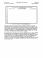
After you have completed the initial dialog as shown in Figure 6.22, BFRESTOR will
prompt you to mount the first of the backup diskettes (generated by BFBACKUP) on
the drive you specified and press <enter> (Figure 6.23).
Insert the first backup disk in drive
Figure 6.23
0
and press <ENTER>:
~
Prompting for the First Diskette
If, in response to the prompt of Figure 6.22, you mount a diskette that was not
generated by BFBACKUP, you will be presented with the display shown in Figure
6.24. At this point you have the option of looking at the directory of either the
source or destination disks or of trying another source diskette. Viewing the
directories can be useful for figuring out what diskette you actually did mount.
The format of the directory display is similiar to that shown in Figure 6Zl except
that the file names fill the entire screen. In Figure 6.24, the user elects to try
another diskette. After this option is selected, BFRESTOR returns to the prompt of
Figure 6.23.
1:
2:
3:
4:
5:
6:
»»
Disk on drive
D· is not a valid backup disk.
OPTIONS:
S - View Source directory
7:
o - Vjew Destination directory
8:
9:
10:
11:
12:
T - Try another disk on Source drive
Enter your choice here: T<enter>
Figure 6.24
Console Display If a Non-Backup Diskette Is Mounted
If the diskette you mount was generated by BFBACKUP but is not the first diskette
in the series for the file, you will be presented with a display as shown in Figure
6.25. This display tells you the name of the file on the backup diskette and the
position of this diskette in the backup series (Line 6.25-1). Since there is nothing of
interest in the directory of the backup diskette, the only options available to you
UTILITY PROGRAMS
page 6.16
BFRESTOR
P&T CP/M 2
RS Hard Disk Addendum
at this time are to look at the directory of the destination disk or try another
source diskette. In Figure 6.25 the user elects to try another source diskette.
After this option is selected, BFRESTOR returns to the prompt of Figure 6.23.
1:
2:
3:
4:
5:
Disk on drive
D
Is backup disk I 2
for the fl Ie
BIGFILE.EXT
OPTIONS:
D - View Destination directory
6:
7:
8:
T - Try another disk on Source drive
9:
10:
Enter your choice here: T<enter>
Figure 6.25
Display If the Wrong Backup Diskette Is Mounted
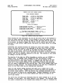
If the mounted diskette is the first in the backup series, BFRESTOR proceeds to
read it and present the display shown in Figure 6.26. On Line 6.26-6, BFRESTOR
reports the name of the file that was backed up onto the diskette. On Line 6.26-8,
the total size of the file is displayed and on Line 6.26-9 the amount of available
space on the destination drive is displayed. If there is not enough space on the
destination drive to restore the entire file, BFRESTOR displays the message "NOT
ENOUGH SPACE" as shown on Line 6.26-9. On Line 6.26-11, BFRESTOR shows the
name which will be used for the restored file. Note that it defaults to the same
name the file had when it was backed up.
BFRESTOR then presents the options you have at this point (Lines 6.26-13 through
6.26-18) and requests that you enter the option you want on Line 6.26-ID. In Figure
6.26 the user selects the option to look at the directory of the destination drive.
While viewing the destination drive directory, you may delete files (if you wish) to
make room for the file to be restored.
1:
2:
3:
4:
5:
6:
7:
Pickles & Trout
BIg-File Restore Utility
-
ver 1.xxx
( Press <BREAK> to quit, <F1> to restart)
Disk on drive
D
Is the
first
backup disk for the file
Total size of Source file :
Space on Destination disk C:
8:
9:
10:
11:
12:
13:
14:
15:
16:
17:
18:
Output file-name:
BIGFILE.EXT
1456 K
0 K <-- NOT ENOUGH SPACE
C:BIGFILE.EXT
OPTIONS:
R
C
D
T
-
Restore fl Ie
Change output fl Ie name
View Destination directory
Try another disk on Source drive
19:
20:
Enter your choice here: D<enter>
Figure 6.26
Console Display After First Diskette Is Mounted
The directory display has the form shown in Figure 6Z1. All files in the directory
under the current user number are displayed including any files that have the "SYS"
attribute set so that they do not show in a standard directory display. Only a
limited number of directory entries are displayed at anyone time since the rest of
the space on the display is needed for other information. The size of the file
being restored and the total available space on the destination disk are shown on
Lines 6.27-13 and 6.27-14. The available options are displayed on Lines 6.27-17 through
6.?:l-22.
UTILITY PROGRAMS
P&T CP/M 2
page 6.17
BFRESTOR
RS Hard Disk Addendum
The "B" option moves you back to the beginning of the directory in case you want
to go through it again. The "D" option moves you on to the next set of the
directory entries. On Line 6.27-24, the user selects the "D" option to move on to
the next set of directory entries.
1:
2:
3:
4:
5:
6:
7:
8:
9:
10:
11:
12:
13:
14:
15:
16:
17:
18:
19:
10:
21:
22:
23:
24:
Directory (including "hidden" files)
C:
C:
C:
C:
C:
C:
C:
ASM
DUt-F
COM
COM
CRT
DEF
DDT
.
DATIME
COM
DUt-F
COM
DDCHECK
ASM
.
COM
More directory entries fol low •
-------------------------------------------------------------------------------Total size of Source file : 1456 K
Space on Destination disk C:
0 K <-- NOT ENOUGH SPACE
OPTIONS:
B - Go to beginning of directory
0 - View more directory entries
X - Delete a file
E - Exit directory listing
Enter your choice here: D<enter>
Figure 6.27
Displaying the Destination Directory
The last set of directory entries is displayed as shown in Figure 6.28. Note that
there are only 3 options available at this point since the "D" option (to display
more entries) has no meaning at this point. On Line 6.28-23 the user selects option
"X" to delete a file. It is not necessary that the name of the file to be deleted
appear on the console at the time the "X" option is selected nor must you be at
the end of the directory to select the "X" option.
1:
2:
3:
4:
5:
6:
7:
8:
9:
10:
Directory (Including "hidden" files)
C:
c:
C:
C:
SETCCB
COM
FILEI
.
BIGFILE
OAT
FILE2
FILE3
OAT
OAT
EXT
End of directory listing.
11:
12:
13:
14:
15:
16:
17:
18:
19:
20:
21:
22:
23:
24:
Total size of Source file :
Space on Destination disk C:
1456 K
0 K
<-- NOT ENOUGH SPACE
OPTIONS:
B - Go to beginning of directory
X - Delete a file
E - Exit directory listing
Enter your choice here: X<enter>
Figure 6.28
Display of Last Set of Directory Entries
UTILITY PROGRAMS
page 6.18
BFRESTOR
P&T CP/M 2
RS Hard Disk Addendum
After the "X" option is selected, BFRESTOR asks you for the name of the file to
be deleted as shown in Figure 6.29. On Line 6.29-17 you may just press <enter> to
return to the previous display without erasing a file or you may enter a file name
as shown.
1:
2:
3:
4:
5:
6:
7:
8:
9:
Directory (Including "hidden" files)
C:
C:
C:
C:
SETCCB
COM
FILE1
.
OAT
FILE2
OAT
FILE3
OAT
BIGFILE EXT
End of directory listing.
10:
11:
Total size of Source fl Ie :
Space on Destination disk C:
12:
1456 K
oK
<- NOT ENOUGH SPACE
13:
14:
15:
16:
Enter name of fl Ie to delete
or just press <ENTER> to skip.
17:
18:
File to de lete:
BIGFILE.EXT<enter>
Figure 6.29 Deleting a FI Ie
After you enter the name of the file to delete, BFRESTOR will try to erase it. If
it is successful, it will return to the previous display with the menu of options. If
the file does not exist, BFRESTOR will display an error message and ask for the
file name again. If the File is set to "read/only" status, BFRESTOR will present
the display shown· in Figure 6.30. You are informed that the file you specified is
"read/only" (Line 6.30-14) and asks you if you actually want it deleted (Line 6.30-16).
If you respond affirmatively, BFRESTOR will delete the file and return to the menu
of options. If you respond negatively, BFRESTOR will take no action and return to
the menu of options. In Figure 6.30, the user elects to erase the file.
1:
Directory (including "hidden" files)
4:
c:
c:
2:
3:
5:
6:
7:
8:
9:
10:
11:
12:
13:
C:
C:
SETCCB
COM
FILE1
.
BIGFILE
OAT
FILE2
OAT
FILE3
OAT
EXT
End of directory listing.
-------------------------------------------------------------------------------Total size of Source fl Ie : 1456 K
Space on Destination disk C:
o K <-- NOT ENOUGH SPACE
14:
15:
C:BIGFILE.EXT
16:
Do you wish to delete It? (YIN): Y<enter>
Is set to Read/Only status.
17:
Figure 6.30 Display If You Try to Delete a Read/Only File
As files are deleted, the display of available space on the destination disk is
, changed to reflect the space freed by the deletion. You may delete as many files
as you wish to make enough space available to receive the file being restored.
Note that after a file is deleted, you are returned to the beginning of the
directory. Figure 6.31 shows the last directory display after just enough files have
been deleted to make room for the file being restored.
page 6.19·
BFRESTOR
UTILITY PROGRAMS
P&T CP/M 2
RS Hard Disk Addendum
1:
2:
3:
4:
5:
6:
7:
8:
9:
10:
Directory (Including "hidden" files)
c:
SETCCB
COM
FILE1
OAT
FILE2
C:
C:
C:
OAT
FILE3
OAT
End of directory listing.
11:
12:
13:
14:
15:
16:
17:
Total size of Source file :
Space on Destination disk C:
1456 K
1456 K
OPTIONS:
18:
19:
B - Go to beginning of directory
X - Delete a file
E - Exit directory listing
20:
21:
22:
23:
24:
Enter your choice here: E<enter>
Figure 6.31
Console Display After Deleting Files to Make Room
On Line 6.31-23, the user selects the "E" option to leave the directory display and
return to the display of Figure 6.26. At this time you may decide that you want to
restore the file under another name. To do this the "C" option in Figure 6.26 is
selected After selecting this option, BFRESTOR will prompt you for a new output
file name as shown in Figure 6.32. You may change the output file name as many
times as you like before beginning the restore operation.
1:
2:
3:
4:
5:
6:
7:
Disk on drive D Is the
first
backup disk for the fl Ie BIGFILE.EXT
Enter new output fl Ie name below
or just press <ENTER> to leave as Is.
Current output file-name:
New output file-name:
C:BIGFILE.EXT
BIGFILE.NEW<enter>
Figure 6.32 Changing the Output File Name
When the "R" operation is selected on Line 6.26-21), the restore operation is started.
While the restoration is taking place, BFRESTOR presents a console display as
shown in Figure 6.33. On Line 6.33-5 a running tally of the amount of data that has
been transferred is displayed.
1:
2:
3:
4:
5:
Restoring fl Ie C:BIGFILE.NEW
Reading backup disk I
119 K
Figure 6.33 Restoring from the First Diskette
If you have requested a verification, BFRESTOR will make a second pass through
the data that was transferred from this source diskette to check that it was copied
accurately. While this verification is taking place, the display will look like Figure
6.34 up to Line 6.34-6. On Line 6.34-5 a running tally of the amount of the file that
has been verified is displayed. After all operations for this diskette have been
completed, the message shown on Line 6.34-7 is displayed.
page 6.20
BFRESTOR
UTILITY PROGRAMS
RS
P&T CP/M 2
Hard Disk Addendum
Restoring fi Ie C:BIGFILE.NEW
1:
2:
3:
Verifying backup disk I 1
4:
5:
594 K
6:
7:
Backup disk I l l s completed.
Figure 6.34
Verifying the Data Restored from the First Backup Diskette
You will be prompted for each diskette in the backup series with a display similiar
to that shown in Figure 6.23. After the last diskette in the series is completed, a
display like that shown in Figure 6.35 will be presented After acknowledging the
display by pressing <enter>, BFRESTOR will start over again at the beginning. You
may restore as many files as you wish and then press (break> to return to the
command level of the system.
.
1:
Restoring fl Ie C:BIGFILE.NEW
2:
3:
Verifying backup disk I 3
4:
5:
6:
7:
8:
Backup disk I 3 Is completed.
FI Ie restore operation complete.
9:
Figure 6.35
Console Display After Restoration Is Complete
Using BFRESTOR • Command Line Mode
In the command line mode of operation, all of the information regarding the source
and destination drives and file names is specified on the command line that
executed BFRESTOR. Figure 6.36 shows the form of such a command line. The "s:"
would be replaced with the logical drive letter of the source drive. Similarly the
"d:" would be replaced by the logical drive letter of the destination drive.
"filename.ext" is optional and, if present, will be used as the name for the output
file. If it is not present, the file will be restored under the same name it had
when it was backed up. The "V" is also optionaL If it is present, a verification
pass will be done otherwise no verification pass will be performed
A>BFRESTOR s: d: fllename.ext V<enter>
Figure 6.36 Command Line to Execute BFRESTOR In Command Line Mode
. When the command line mode of BFRESTOR is used, the program begins at the point
represented by Figure 6.23. When the restoration is completed, BFRESTOR will
return immediately to the operating system if it was executed in the command line
mode.
The following examples show command lines that could be used with BFRESTOR:
BFRESTOR D: C:
Restores a file previously backed up by BFBACKUP from diskettes to be
mounted on drive D to drive C. The restored file will have the same name it
had when it was backed up. No verification is done.
P&T CP/M 2
UTILITY PROGRAMS
RS Hard Disk Addendum
page 6.21
BFRESTOR
BFRESTOR E: A: DATABASE.BIG V
Restores a file previously backed up by BFBACKUP from diskettes to be
mounted on drive E to drive A. The restored file will be named
DATABASE.BIG regardless of the name it originally had. Read back
verification is performed on the restored file.
Possible Error Messages
Non-modular system, not compatible with this program.
BFRESTOR is designed to work only with P&T CP1M 2.2m and subsequent
releases. You have attempted to run the program on an earlier release.
Open Error on Source drive
Indicates that an error occurred while attempting to open a file on the source
drive. BFRESTOR is restarted after an error of this type.
Open Error on Destination drive
Indicates that an error occurred while attempting to open a file on the
destination drive. BFRESTOR is restarted after an error of this type.
Close Error on Source drive
Indicates that an error occurred while attempting to close a file on the source
drive. BFRESTOR is restarted after an error of this type.
Close Error on Destination drive
Indicates that an error occurred while attempting to close a file on the
destination drive. BFRESTOR is restarted after an error of this type.
Read Error on Source drive
Indicates that a disk error occurred while reading from the source drive.
BFRESTOR is restarted after an error of this type.
Read Error on Destination drive
Indicates that a disk error occurred while reading from the destination drive.
BFRESTOR is restarted after an error of this type.
Write Error on Source drive
Indicates that a disk error occurred while writing to the source drive.
BFRESTOR is restarted after an error of this type.
Write Error on Destination drige
Indicates that a disk error occurred while writing to the destination drive.
BFRESTOR is restarted after an error of this type.
Invalid drive name
Indicates that the logical drive letter just entered in the prompted mode is not
in the range A - P.
Invalid file name
Indicates that the file name just entered in the prompted mode contains illegal
characters.
Drive letter in file name differs from Destination drive name
Indicates that the drive designation given with the file name just entered in the
prompted mode does not match the destination drive previously entered. This
page 6.22
BFRESTOR
UTILITY PROGRAMS
P&T CP/M 2
RS Hard Disk Addendum
message may also be displayed in the command line mode if the drive designation
given with the new destination file name does not match the logical drive letter
entered for the destination drive.
Source and Destination cannot be' the same drive
Indicates that you have specified the same logical drive for both the source and
destination drives. This is not permitted when running BFRESTOR. This message
can be given in either the prompted or command line mode.
That drive is not on the system
Indicates that the logical drive just specified for the source or destination drive
in the prompted mode is not defined tor this system.
Source drive is a hard disk.
Indicates that the source drive you have specified is a hard disk drive.
BFRESTOR restores from diskettes only hence this is "not allowed.
Not a valid response, please re-enter
Indicates that the response you entered is not among the acceptable responses
for the question asked. The acceptable responses are usually indicated in the
question.
... VERIPY ERROR ...
This message is displayed if an error is discovered while doing the verification
pass. After a verify error occurs, you are given the option of retrying the
restore operation starting with the current diskette in the backup series or
aborting the restoration.
Disk on Source drive is an incomplete backup disk
An incomplete backup diskette can be caused by aborting the backup operation
as the diskette was being generated. BFRESTOR detects this condition and
displays this message. It typically means that you mounted the wrong diskette
and should try another one. BFRESTOR will prompt you again for the diskette
it wants.
Disk on Source drive is not a backup disk for filename.ext
Once you have started a restore operation, this message will be displayed if you
mount a diskette which was not generated by BFBACKUP or is part of a backup
series for another file. "filename.ext" will be replaced with the name of the file
being restored. You have probably gotten your diskettes mixed up. BFRESTOR
will prompt you again for the diskette it wants.
Disk on Source drive is a backup disk from another series.
This message indicates that the diskette you have mounted is from another series
of diskettes generated by BFBACKUP while backing up the same file. This
typically indicates that you have gotten your diskettes mixed up. BFRESTOR
will prompt you again for the diskette it wants.
Disk on Source drive is not a valid backup disk.
This message indicates that the diskette you have mounted was not generated by
the BFBACKUP program.
Disk on Source drive is backup disk I N
This message is given any time that a wrong disk in the backup series is found
on the source drive. This can be caused by mounting a diskette out of order or
one that has already been restored.
P&T CP/M 2
RS Hard Disk Addendum
UTILITY PROGRAMS
page 6.23
BFRESTOR
NOT ENOUGH SPACE
This message indicates that there is not enough space on the destination drive
to restore the entire file. You should restore to another drive or delete files
from the specified destination drive until there is enough space available.
Can't find file x:filename.ext
Indicates that the file "x:filename.ext" which you have requested to be erased
could not be found on the destination drive. Check your typing to make sure
you entered the file name correctly.
»»
Error: Bad Source drive name.
Indicates that the logical drive letter entered on the command line for the
source drive was not in the range A - P.
»»
Error: Bad Destination drive name
Indicates that the logical drive letter entered on the command line for the
destination drive was not in the range A - P.
»»
Error: Bad file name
Indicates that the file name entered on the command line contained illegal
characters.
»»
Error: Drive letter in file name differs from Destination drive name
Indicates that the drive designation given with the destination file name on the
command line does not match the logical drive letter specified for the
destination drive.
»»
Error: Bad Verify Option specified
Indicates that characters other than "V" were found following the file name on
the command line. Note that this message can be caused by specifying an
extension longer than three characters for the file name.
»»
Error: Source drive not on system
Indicates that the source drive specified on the command line is not defined for
this system.
»»
Error: Destination drive not on system
Indicates that the destination drive specified on the command line is not defined
for this system.
»»
Error: Source and Destination eannot be the same drive
Indicates that the command line specifies the same logical drive for both the
source and destination drives. This is not. permitted when running BFRESTOR.
»»
Error: Source drive is a hard disk.
Indicates that the source drive specified on the command line is a hard disk
drive. BFRESTOR restores from diskettes only hence this is not allowed.
page 6.24
BKMOUNT
6.5
UTILITY PROGRAMS
P&T CP/M 2
RS Hard Disk Addendum
Utility name: BKMOUNT
Purpose: To prompt the user to mount a new diskette when
backing up files with FILEBACK.
General Description
The BKMOUNT utility program prompts the user to mount a new diskette on a given
drive. It then waits until the user presses the <enter> key. After the user presses
<enter>, BKMOUNT performs a disk system reset (CP/M BDOS function 13) and
returns to the operating system via a warm boot. BKMOUNT is designed to be
executed from a SUBMIT file when it is necessary to have the user mount a new
diskette.
While this program is intended for use with the FILEBACK utility, it may also be of
some use in making up your own SUBMIT files.
Using BKMOUNT
The BKMOUNT program is executed with a command line of the form shown in
Figure 6.37. The "z" in the command line should be replaced by the drive on which
the new diskette is to be mounted.
(
Figure 6.37
A>BKMOUNT .<enter> )
Command Line to Execute BKMOUNT
When BKMOUNT is executed, it will display the prompt shown in Figure 6.38 on the
console. The liZ" in the prompt will be replaced by the drive letter specified on
the command line that executed BKMOUNT. After displaying the prompt line,
BKMOUNT will wait for the <enter> key to be pressed. When <enter> is pressed,
BKMOUNT will reset the disk system with BDOS function 13 and return to the
system via a warm boot. This will cause any SUBMIT file which is in progress to
resume.
Mount an empty diskette on drive z and press <enter> when ready to continue
Figure 6.38 Prompt Given by BKMOUNT
Possible Error Messages
None
P&T CP/M 2
UTILITY PROGRAMS
RS Hard Disk Addendum
6.6
Utility name:
Purpose:
page 6.25
CLEARDIR
CLEARDIR
To wipe clean the directory portion of a logical drive on
a hard disk.
General Description
The CLEARDIR utility program is designed to provide an easy method of clearing
the directory area of a logical disk which is assigned to a hard disk drive. It
completely obliterates whatever is in the directory area of the disk and pays no
attention to user number or read only file status.
If you have used the P&T HFORMAT program on a hard disk, it will not be
necessary to use CLEARDIR. However, if you have used a hard disk with TRSDOS
and do not reformat it with HFORMAT, you should use CLEARDIR on all logical
drives on the hard disk. This will insure that no garbage is left in the directory
areas that will interfere with the operation of P&T CP/M 2.
Please note that the operation of CLEARDIR is irreversible. Once you have run the
program on a disk, there is no way to recover the files on that disk. Also note
that if you have used HDCHECK to lock out flawed sectors on a logical drive
assigned to a hard disk, CLEARDIR will "unlock" them. If a logical drive includes
flawed sectors, you must use HDCHECK on it after using CLEARDIR.
Using CLEARDIR
Figure 6.39 shows a typical console dialog for using CLEARDIR. The command shown
on Line 6.39-1 will execute CLEARDIR.
1:
2:
3:
4:
5:
6:
7:
8:
9:
10:
11:
12:
13:
14:
15:
16:
17:
18:
19:
20:
A>CLEARDI R<enter>
Directory Erase Utility - ver 2.xx
(c) 1981, 1983 Pickles & Trout - all rights reserved
This program allows the quick erasure of the directory on
logical drives which are assigned to hard disk drives. It
erases all files from all user numbers regardless If they
are read only entries or not.
»»
USE THIS PROGRAM WITH EXTREME CARE!! ««
Enter logical drive on which to clear directory (x to exit): E<enter>
You have requested that the directory on logical drive E
be cleared. Note that this operation will result In the
LOSS OF ALL FILES ON LOGICAL DRIVE E.
Do you want to continue (YIN)? Y<enter>
Enter logical drive on which to clear directory (x to exit): X<enter>
A>
Figure 6.39
Example of Using CLEARDIR
CLEARDIR first displays the messages shown on Lines 6.39-2 to 6.39-11. It then asks
you for the logical drive which is to have its directory cleared. At this point you
should enter the letter corresponding to the drive. In this example, drive E was
specified. Since the effect of CLEARDIR is completely irreversible, it warns you
page 6.26
CLEARDIR
UTILITY PROGRAMS
P&T CP/M 2
RS Hard Disk Addendum
that all of the files on the drive will be lost (Lines 6.39-14 to 6.39-16) and asks you
if you want to continue (Line 6.39-17). If you respond negatively at this point,
CLEARDIR will prompt you again for a drive letter. If you respond affirmatively,
CLEARDIR will proceed to· erase all of the directory entries. You may clear the
directories on as many logical drives as you wish merely by continuing to enter
drive letters when asked for them. When you are finished clearing directories,
enter an "X" ~s shown on Line 6.39-19 and CLEARDIR will retum you to the
command level of the system.
Possible Error Messages
Please respond with the letters A - P only.
This message is displayed if you enter an improper letter when specifying the
drive which is to have its directory cleared.
That logical drive is not on the system.
This message is displayed if you specify a logical drive that is not defined on
the system.
That logical drive is not a hard disk.
CLEARDIR will work only with hard disk drives.
you attempt to use it on a diskette disk drive.
This message is displayed if
Please respond with Y or N only.
This message is displayed if you respond with characters other than "Y" or "N"
to the query about continuing with the clearing operation.
Error during directory write operation.
This message is given if a disk error should occur while CLEARDIR is actually
writing to the directory area of the disk.
P&T CP/M 2
RS Hard Disk Addendum
6.7
UTILITY PROGRAMS
page 6.27
FILEBACK
Utility name: FILEBACK
Purpose: 1b generate SUBMIT files that will back up all files
smaller than the capacity of a diskette from a hard disk
to multiple diskettes. The SUBMIT program is then used
to start the backup.
General Description
A problem in backing up files from a logical drive a~igned to a hard disk is that
there is usually more information stored on the hard disk than will fit on a single
diskette. Using PIP with wildcards or FASTCOPY will result in the backup stopping
with an error me~age after the destination diskette fills up.
FILEBACK generates SUB files to use PIP to backup all of the files stored under
the current user number from one logical drive to multiple diskettes. It orders the
files to be transferred in such a way as to fill each diskette as completely as
. possible before moving on to another diskette.
Since there is a limit to the size of a SUB file, FILEBACK will generate a series of
SUB files, if necessary, and cause them to chain from one to another. The very
last action of the last SUB file is to erase all of the SUB files that were used in
the backup operation. FILEBACK will always create the SUB files on logical drive
A and will give them ~ames of the form shown in Figure 6.40.
BKUPx.SUB
x Is replaced by letters A, B, C, •••
Figure 6.40 Form of SUB File Names Created
by
FILEBACK
FILEBACK includes a special option if you are using the P&T Advanced Command
Processor (P&T ACP) on your system. If· this option is used, the contents of the
SUB file created by FILEBACK are modified to be consistent with the slightly
different form of command lines recognized by the P&T ACP. Figure 6.41a shows
the form of a SUB file normally created by FILEBACK. Figure 6.41b shows the form
of a SUB file created by FILEBACK when the "IA" option is used.
page 6.28
FILEBACK
UTILITY PROGRAMS
XSUB
BKMOUNT 0
PIP
D:=C: F ILE.ll ovrl
D:=C:FILE.2Iovrl
D:=C:FILE.26Iovrl
D:=C:FILE.99Iovrl
.
BKMOUNT 0
PIP
D:=C:SETUP.COMlovrl
D:=C:FORMAT.COMlovrl
.
D:=C:SDTEST.COMlovrl
D:=C:DDCHECK.COMlovrl
D:=C:TRS2CPM.COMlovrl
.
XSUB
BKMOUNT 0
PIP
<D:=C:FILE.llovrl
<D:=C:FILE.2Iovrl
<D:=C:FILE.26Iovrl
<D:=C:FILE.991ovrl
<•
BKMOUNT 0
PIP
<D:=C:SETUP.COMlovrl
<D:=C:FORMAT.COMlovrl
.
<D:=C:SDTEST.COMlovrl
<D:=C:DDCHECK.COMIovrI
<D:=C:TRS2CPM.COMlovrl
<•
ERA A:BKUP1.SUB
ERA A:BKUP1.SUB N
Figure 6.41a Standard CCP
Figure 6.41
P&T CP/M 2
RS Hard Disk Addendum
Figure 6.41b P&T ACP
Examples of :he Contents of SUB Files Created by FILEBACK
FILEBACK can only backup files whose size is less than or equal to the capacity of
a diskette. You can instruct FILEBACK to consider the destination diskettes to be
either single or double sided (the diskettes are always considered to be double
density). For single sided destination diskettes the maximum size file that can be
backed up is 596 Kbytes while for double sided destination diskettes the maximum
size file is 1210 Kbytes. Any file larger than these limits is reported on the console
with a message indicating that BFBACKUP should be used to back it up.
The SUB files generated by FILEBACK make use of several system utility programs.
Figure 6.42a lists the programs that must be resident on logical drive A in order to
run the backup process with the standard CCP. Figure 6.42b shows the programs
required to run the backup process if you are using the P&T ACP. Only the copy
of PIP that was supplied with the system should be used in the backup process. It
has been patched to provide a means for SUBMITted files to exit PIP and return to
the operating system. If unpatched copy of PIP is used, the backup process will
not work properly.
~ XSUB
SUBMIT
BKMOUNT
PIP
"
Figure 6.42a Standard CCP
Figure 6.42
Figure 6.42b P&T ACP
Fi les Required to Run the SUB Fi les Created by FILEBACK
The files transferred to the diskettes during the backup process will be saved as
normal disk files. They may be accessed just like any other disk files. The files
may be restored to a disk drive using standard file transfer utility programs like
PIP and FASTCOPY.
P&T CP/M 2
RS Hard Disk Addendum
UTILITY PROGRAMS
page 6.29
FILEBACK
Using FILEBACK
All instructions are given to FILEBACK on the command line that executes it. If no
instructions are included on the command line, FILEBACK displays a brief summary
of the information that should appear on the command line as shown in Figure 6.43.
A>FILEBACK<enter>
Fileback version 1.xx
Copyright 1982,83 Pickles & Trout
The command line to execute FILEBACK Is as follows:
FILEBACK d:fllename.typ [: Izz la
L IA needed If using P&T ACP
ISS for single sided destination diskettes or
IDS for double sided
(optional - If omitted, defaults to ISS)
L
I
destination drive (cannot be A:)
source fl Ie specification, wildcards allowed
d: Is equivalent to d:*.*
A>
Figure 6.43 Help Display of FILEBACK
The command line may have either 2, 3, or 4 parameters on it. The parameters
must be separated from one another by at least one space. The first parameter
specifies the logical drive from which the backup is to be done (the source drive)
and an optional file name. The file name may be either a unique or a wildcard file
name. If the file name is present, only file names matching it will be placed in the
SUB file created by FILEBACK. If no file name is given with the source drive
designation (e.g. "C:") all files will be transferred. This is the same as the wildcard
specification n*.*".
The second parameter is the logical drive on which the diskettes will be mounted
during the backup operation. The third parameter is optional and, if present,
indicates the type of diskettes onto which the backup operation is to be performed.
The fourth parameter is also optional and, if present, indicates that SUB files for
the P&T ACP are to be generated.
Several examples of command lines for using FILEBACK are shown in Figure 6.44.
~
FILEBACK A: 0:
Backup all files from drive A to drive D.
The destination diskettes are single sided.
FILEBACK A: 0: IDS
Backup al I files from drive A to drive D.
The destination diskettes are double sided.
FILEBACK A:*.COM E: IA
Backup a I I f I Ies with the extens Ion "COM"
from drive A to drive E. The destination
diskettes are single sided and the P&T ACP
Is In use.
FILEBACK B:*.182 0: IDS IA
Backup all files matching "*.182" from drive
B to drive D. Destination diskettes are
double sided and the P&T ACP Is In use.
~
Figure 6.44
...
...
Sample Command Lines for Using FILEBACK
The console display you might see for a typical usage of FILEBACK is shown in
Figure 6.45.
page 6.30
FILEBACK
UTILITY PROGRAMS
I:
2:
3:
P&T CP/M 2
RS Hard Disk Addendum
A>FILEBACK B: D:<enter>
FI leback version l.xx
Copyright 1982,83 Pickles & Trout
4:
5:
6:
Creating SUB files to backup *.* on drive B to drive D.
Destination diskettes are single sided.
7:
8:
9:
10:
11:
12:
13:
14:
15:
16:
You wil I require 4 blank double density, single sided diskettes to
backup the files from drive B
Log onto drive A and type
SUBMIT BKUPA
to begin the backup process
A>
Figure 6.45
Example of Using FILEBACK with Single Sided Diskettes
Since no instruction about the type of destination diskette was given on Line 6.45-1,
FILEBACK assumes they will be single sided. On Lines 6.45-2 and 6.45-3 FILEBACK
gives an opening message indicating its version number. On Lines 6.45-5 and 6.45-6
FILEBACK summarizes what it is doing so that you can verify that it is doing what
you want. After it is finished, FILEBACK tells you how many diskettes you will
need to perform the entire backup (Lines 6.45-9 and 6.45-10). It then reminds you of
what you must do to start the backup (Lines 6.45-12 through 6.45-14).
If you have the P&T ACP, you may begin the backup process at once by merely
executing Line 6.45-13 directly from the screen. To do this press the comma key
followed by <enter>. This will put you in the screen editing mode. Then use the
<up arrow> key to move the cursor up to the line on the display corresponding to
Line 6.45-13 and press <enter> again. P&T ACP will automatically execute the line
to begin the backup.
After you ar~ returned to the command level of the operating system, you may
inspect the generated SUB files if you wish. The SUB files are generated assuming
that the destination diskettes will be completely empty (ie. newly formatted). If
you alter the SUB files or if the diskettes you use are not completely empty, they
will probably fill up during file transfer and cause PIP to report a "DISK WRITE
ERROR".
Possible Error Messages
Invalid source drive
This message indicates that no source drive was specified or the drive letter
specified for the source drive is not in the range of A - P.
Invalid source file specification
This message indicates that there is something wrong with the file name you
specified for the source file. Typically this is due to more than one character
appearing before the colon that separates the logical drive letter from the file
name.
Invalid destination drive
This message indicates that that no destination drive was specified or the drive
letter specified for the destination drive is not in the range of A - P.
P&T CP/M 2
RS Hard Disk Addendum
UTILITY PROGRAMS
page 6.31
FILEBACK
Destination drive cannot be drive A
Since the SUB files and the intermediate file that are used by the SUBMIT
process are stored on drive A, it is not possible for drive A to be the
destination drive. You should use another logical drive as the destination.
Source and destination drive cannot be the same
This message indicates that you have specified the same drive letter for both
the source and destination drives. This is not allowed since it would result in
transferring files from a drive to itself.
ffffffff.xxx is too large for one diskette - use big file backup program.
This message is displayed when FILEBACK finds a disk file that is too large to
fit on an empty diskette. "ffffffff.xxx" will be replaced with the name of the
file that is too large. The BFBACKUP utility program can be used to backup
files that are larger than the capacity of a single diskette. The file named in
this message will not be included in the SUB file created by FILEBACK.
Error while creating BKUPx.SUB
This message is displayed if a disk system error occurs while creating the SUB
file of the name shown. The "x" in the SUB file will be replaced by letter that
changes depending on how many SUB files have already been created. This error
is typically caused by insufficient space on logical drive A or its directory for
another file.
Ou t of memory, too many files
FILEBACK begins by reading the names of all the files that match the
specification given on the command line into memory. It then begins to create
the SUB files to perform the backup operation. If you have a very large number
(usually more than 10(0) of files on the source drive, FILEBACK may run out of
memory before it has read all of the file names. If you should get this error
you should backup only a portion of the files on the disk at one time by
specifying wild card file names on the command line of FILEBACK.
No files found
This message indicates that no files were found on the source drive that match
the file specification given on the FILEBACK command line.
page 6.32
HDCHECK
6.8
UTILITY PROGRAMS
P&T CP/M 2
RS Hard Disk Addendum
Utility name: HDCHECK
Purpose: To test the section of a hard disk drive assigned to a
logical drive for bad sectors. If any are found, they are
locked out from usage.
General Description
HDCHECK performs a media check on the section of a hard disk which is assigned
to a logical drive. If bad sectors are found they are removed from the pool of
available space so that they will not be used in normal operation.
Sectors on the disk are grouped together into allocation blocks for use by the
operating system. If a bad sector is found on the disk, the entire block to which it
belongs is treated as if it were bad. HDCHECK actually works in terms of these
blocks and many of its messages are given in terms of blocks rather than sectors.
Bad blocks are removed from the pool of available blocks by creating special
directory entries which make it appear that the bad blocks are already used by a
file. These directory entries are not normally visible in directory listings nor are ,
they accessible to normal system utilities. These directory entries can be erased by
the CLEARDIR and HFORMAT utility programs. If you use CLEARDIR or HFORMAT
on a logical drive that contains bad sectors, you should use HDCHECK on that drive
before using the drive for anything. If you use HDCONFIG to reconfigure a logical
drive on the hard disk, you should run HDCHECK on that drive since the block
assignments may have been changed by the reconfiguration.
The test made by HDCHECK does not affect any data stored on logical drive being
tested. You can run it any time you wish to check that everything is OK on a
given drive. If it finds bad blocks that are already in use by a file, HDCHECK will
lock them out from subsequent usage. The blocks will still be accessible as part of
the file until the file is deleted (or in some cases, modified). After the file is
deleted, the bad block cannot be reused. This allows you to attempt to recover as
much information as possible from a file that includes a bad block. If files are
found which include bad blocks, they are reported on the console so you will be
aware of the problem.
The hard disk containing the logical drive being tested may be write protected (by
having its write protect switch on) during the checking operation. The drive must
not be write protected when the bad blocks (if any) are marked.
Using HDCHECK
The command line for executing HDCHECK is shown in Figure 6.46.
A>HDCHECK<enter>
Figure 6.46 Command Line to Execute HDCHECK
While HDCHECK is executing there will be two lines at the top of the screen
identifying the program. Most of the user interaction (such as prompting for the
drive to test) will occur in the middle of the screen. Error messages will be
UTILITY PROGRAMS
P&T CP/M 2
RS Hard Disk Addendum
page 6.33
HDCHECK
displayed on the last 3 lines of the screen. Other messages giVing the results of
operations will also be displayed on the last 3 lines of the screen. While HDCHECK
is waiting for the user to acknowledge a message, it will flash the line shown in
Figure 6.47 on the bottom line of the display.
(
(press <enter> to continue)
Figure 6.47
)
Message Flashed at Bottom of Display while Waiting for User
After HDCHECK starts execution, it will present a display such as the one shown in
Figure 6.48. On line 6.48-9 you are asked to enter the letter of the logical drive
you want checked or 0 (zero) if you want to return to the system command leveL
Figure 6.48 shows logical drive A being specified for the check.
1:
2:
3:
Radio Shack Hard Disk Check Program - ver l.xx
Copyright 1982 by Pickles & Trout
4:
5:
6:
7:
8:
9:
Enter logical drive (A-P) to check or 0 to quit: A<enter>
10:
11:
Checking track
12:
Figure 6.48
6
Console Display While Checking for Bad Blocks
You may also abort the program and return to the system command level by
pressing the <break> key whenever HDCHECK is requesting keyboard input. If you
press the <break> key, HDCHECK verifies that you want to exit the program by
asking the question shown in Figure 6.49 on the bottom line of the console display.
If you answer affirmatively, you will be returned to the system command leveL If
you answer negatively, you will be returned to the point in the program at which
you pressed <break>. Any time HDCHECK asks a question requiring a "yes/no"
answer, it will accept the characters "Y", "y", "T", "t", and "1" as affirmative
responses and the characters "N", "n", "F", "f", and "0" as negative responses.
(
Do you really want to quit (YIN)?
Figure 6.49
)
Prompt Displayed if You Press <break>
Assuming that a logical drive which is assigned to a hard disk is specified on Line
6.48-9, HDCHECK will proceed to check all tracks assigned to that drive. It displays
the number of each track as it is being checked (Line :6.48-11). If no bad blocks are
found, the message shown in Figure 6.50 is displayed at the bottom of the console
and HDCHECK waits for you to press <enter>. After pressing <enter> HDCHECK will
prompt for another drive to check as shown in Figure 6.48.
No bad blocks found
(press <enter> to continue)
Figure 6.50
)
Message Given If no Bad Blocks are Found
If bad blocks were found on the logical drive, HDCHECK proceeds to mark them so
they will not be used. While it is marking them, the console display will look like
Lines 6.51-1 though 6.51-9. After all of the blocks have been marked, HDCHECK will
UTILITY PROGRAMS
page 6.34
HDCHECK
P&T CP/M 2
RS Hard Disk Addendum
display the message shown on Lines 6.51-22 through 6.51-24 and wait for you to press
<enter>.
Radio Shack Hard Disk Check Program - ver l.xx
Copyright 1982 by Pickles & Trout
1:
2:
3:
4:
5:
6:
7:
8:
Marking Bad Blocks
xx bad blocks found
9:
10:
11:
12:
13:
14:
15:
16:
17:
18:
19:
20:
21:
22:
23:
24:
All bad blocks have been removed from usable space on the disk
(press <enter> to continue)
Figure 6.51
Console Display for Marking Bad Blocks
After you press <enter>, HDCHECK will check for files that are affected by the bad
blocks. If no files are found, the message shown in Figure 6.52 will be displayed.
If files are affected, their names will be listed in a display such as that shown in
Figure 6.53.
No files are affected by the bad block(s)
Figure 6.52
Message Given If no Files are Affected by the Bad Blocks
Radio Shack Hard Disk Check Program - ver l.xx
Copyright 1982 by Pickles & Trout
1
2
3
4
5
6
7
8
9
10
Files that contain bad blocks
fllename.OOl
fllename.006
filename.002 I fllename.003 I fllename.004 I fllename.005
11
12
13
14
15
16
17
18
19
20
21
22
23
24
(press <enter> to continue)
Figure 6.53
Display Given If Files are Affected
by
the Bad Blocks
P&T CP/M 2
Hard Disk Addendum
UTILITY PROGRAMS
RS
page 6.35
HDCHECK
Possible Error Messages
Not a valid response, please re-enter
This message is usually used in conjunction with other messages to indicate that
you made an unexpected response to the prompt. For example, this message
would be given if you entered "Q" as a logical drive letter.
That logical drive is not defined for this system
This message indicates that the logical drive you have specified is not available
on the system and hence cannot be tested.
That drive is not assigned to a hard disk
This message indicates that the logical drive you have requested to be tested is
a not assigned to a hard disk. HDCHECK may only be used on logical drives
assigned to a hard disk.
That drive is not on-line and ready, cannot check
This message is given when HDCHECK finds the drive you have specified not
ready. This is typically caused by the hard disk to which the drive is assigned
not being turned on.
.
This logical drive has more than 50 bad blocks, indicating a severe
hardware problem. Aborting check process.
A typical disk drive will have very few, if any, bad blocks. This message
indicates that something is very wrong with the drive you are checking because
more than 50 bad blocks were found. You may be able to remove some of the
bad blocks by reformatting the drive.
Disk error while marking bad blocks - could not complete
If a disk error occurs while HDCHECK is marking the bad blocks, this error
message is given. If the error was due to a nonrepeating problem, you may be
able to successfully mark the bad blocks by running HDCHECK on the drive
again.
One or more of the bad blocks are in the directory.
Bad blocks in the directory cannot be accommodated.
You might try reformatting this logical drive
(save any files on it first)
or
reconfigure the system so that this logical drive starts in a
different place on the hard disk.
This message is given if bad blocks are found in the directory area of a logical
drive. If reformatting the logical drive does not remove the bad blocks, you
must reconfigure the system so that the the logical drive starts in a different
place on the hard disk (the directory is at the beginning of the logical drive).
Once you have found a location on the disk where there are no bad blocks in
the directory, HDCHECK can be used on the drive.
Drive x is write protected - cannot mark bad blocks
Unprotect if you want the blocks marked
Marking the bad blocks requires writing to the drive. If the write protect
switch on the hard disk is on, it is not possible to mark the bad blocks and this
message is given. After this message is given, you may turn off the write
protect switch and press <enter> for HDCHECK to continue. If you do not tum
off the write p,rotect switch before pressing <enter> HDCHECK will not mark the
bad blocks and will prompt for another drive to check.
page 6.36
HDCHECK
UTILITY PROGRAMS
P&T CP/M 2
RS Hard Disk Addendum
Not enough space in the directory to mark all bad blocks
Since bad blocks are marked (locked out) by creating directory entries, directory
entries must be available for this purpose. This message is given if there are
not enough entries available to mark all of the bad blocks. If you get this
error, you can exit HDCHECK and erase a file or two from the drive you are
checking. This should create enough room in the directory so that you can run
HDCHECK again with success.
UTILITY PROGRAMS
P&T CP/M 2
RS Hard Disk Addendum
6.9
Utility name:
Purpose:
page 6.37
HDCONFIG
HDCONFIG
To configure the disk storage allocation of the hard disk
system.
General Description
The HDCONFIG program allows you to modify the configuration of the disk storage
on your hard disk system. It allows you to modify such parameters as the capacity,
number of directory entries, allocation block size, etc. for each logical drive
assigned to a hard disk. The program is fully discussed in Chapter 7, Configuring
the System, hence it is not described here.
page 6.38
HFORMAT
6.10
UTILITY PROGRAMS
P&TCP/M 2
RS Hard Disk Addendum
Utility name: HFORMAT
Purpose: To format a portion of a hard disk drive and to install a
system bootstrap, on the primary hard disk drive.
General Description
HFORMAT performs two jobs. It allows you to format a portion of a hard disk
drive and it allows you to install a system bootstrap on the primary hard disk drive
(drive 0).
A hard disk must be formatted before it can be used by the operating system. If
you formatted a hard disk with the TRSDOS INIT program, you do not need to
reformat it (however you may need to run the CLEARDffi program as described in
Section 6.6). If you have not formatted a hard disk, you may use the HFORMAT
program (which runs somewhat faster than TRSDOS INIT). When first formatting a
hard disk, it is usually best to format by track numbers (option 2) since this insures
that the entire disk is formatted
HFORMAT has the advantage of being able to format portions of a hard disk while
leaving the rest of it untouched. The portion to be formatted may be specified by
ei ther a range of track numbers or as a logical drive. If you specify a logical
drive, HFORMAT will format only those tracks that are assigned to that logical
drive. You may find it desireable to reformat a logical drive if you wish to change
the programs stored on it. Although it is not necessary to reformat under these
conditions, you may want to start off with an entirely clean logical drive (ie. no
leftover junk from previous uses).
In addition to formatting hard disks, HFORMAT allows you to install a system
bootstrap on the primary hard disk drive (physical hard disk 0). Before this
bootstrap is installed, to boot P&T CP 1M 2 you must hold down the <break> and
<repeat) keys on the keyboard while pressing RESET on the front of the computer.
After the bootstrap is installed, P&T CP1M 2 will automatically boot when you press
the RESET switch, provided the primary hard disk drive is turned on and there is a
system diskette in floppy drive O.
Using HFORMAT
The command line for executing HFORMAT is shown in Figure 6.54.
A>HFORMAT<enter>
Figure 6.54 Command Line to Execute HFORMAT
While HFORMAT is executing there will be two lines at the top of the screen
identifying the program. Most of the user interaction (such as prompting for the
drive to test) will occur in the middle of the screen. Error messages will be
displayed on the last 3 lines of the screen. Other messages giving the results of
operations will also be displayed on the last 3 lines of the screen. While HFORMAT
is waiting for the user to acknowledge a message, it will flash the line shown in
Figure 6.55 on the bottom line of the display.
UTILITY PROGRAMS
P&T CP/M 2
RS Hard Disk Addendum
(
(press <enter> to continue)
Figure 6.55
page 6.39
HFORMAT
)
Message Flashed at Bottom of Display Whl Ie Waiting for User
The various different options available in HFORMAT are displayed as shown in
Figure 6.56.
1:
2:
3:
4:
5:
6:
7:
8:
9:
Radio Shack Hard Disk Format Program - ver l.xx
Copyright 1982 by Pickles & Trout
functions
o. return to CP/M
1. Format by logical drive
2. Format by tracks
3. Write bootstrap to drive 0
10:
11:
12:
13:
14:
15:
16:
17:
enter function to perform:
Figure 6.56
Main Menu of HFORMAT
In addition to using option 0 to return to the operating system, you may press the
<break> key at any time HFORMAT is waiting for input from the keyboard. If you
press <break>, HFORMAT will prompt you with the question shown in Figure 6.57. If
you respond affirmatively, HFORMAT will return you to the command level of the
system. If you respond negatively, HFORMAT will return you to the point at which
you pressed <break>. Any time HFORMAT asks a question requiring a "yes/no"
answer, it will accept the characters "Y", "y", "T", "t", and "1" as affirmative
responses and the characters "N", "n", "F", "f", and "0" as negative responses.
Do you
really _
want to _
quit (Y/N)?
)
_
_ _ _....J
(' - - _ _ _
Figure 6.57
Prompt Displayed If You Press <break>
If you select option 1 to format by logical drives, you will be presented with the
first 9 lines of Figure 6.58. On line 6.58-9 you should enter the letter of the logical
drive you wish to format. In the figure, logical drive A is specified. If the logical
drive is assigned to a hard disk, HFORMAT will show you which region of which
hard disk drive is encompassed by the drive (Lines 6.58-11 and 6.58-12).
HFORMAT then reminds you that all data stored on this area of the hard disk will
be destroyed by the format operation (Lines 6.58-14 and 6.58-15) and asks if you want
to go ahead with the format operation (Line 6.58-17). If you respond negatively,
HFORMAT returns to Figure 6.56. If you respond affirmatively, HFORMAT begins
formatting the indicated section of the hard disk. As each track is being
formatted, its track number is shown on Line 6.58-19.
page 6.40
HFORMAT
1:
2:
3:
4:
5:
UTILITY PROGRAMS
P&T CP/M 2
RS Hard Disk Addendum
Radio Shack Hard Disk Format Program - ver 1.xx
Copyright 1982 by Pickles & Trout
6:
7:
8:
9:
10:
11:
12:
13:
14:
15:
16:
17:
18:
19:
Formatting by Logical Drive
Enter logical drive to format (A-P):
A<enter>
Logical drive A includes tracks 1 to 241
on physical drive 0
Remember that all Information In this area will be
destroyed by the format operation.
Do you wish to proceed (YIN)? Y<enter>
Formatting track
Figure 6.58
99
Formatting by Logical Drive
If you select option 2 to format by tracks, HFORMAT will enter into the dialog
shown in Figure 6.59. On line 6.59-9 you are asked to enter the physical hard disk
drive on which you wish to format. Physical drive 0 is the primary hard disk unit,
physical drive 1 is the first secondary hard disk unit, and so forth. If you just
press <enter> on Line 6.59-9, HFORMAT will assume physical hard disk drive O.
1:
2:
3:
Radio Shack Hard Disk Format Program - ver 1.xx
Copyright 1982 by Pickles & Trout
4:
5:
6:
7:
8:
9:
10:
11:
12:
13:
14:
15:
16:
17:
18:
19:
20:
21 :
22:
23:
Formatting by track number
Enter physical hard disk drive on which to format (0-3):
Enter number of heads (surfaces) on drive (1-8):
Enter number of cylinders on drive (1-1024):
Enter first track to format (O-xxxx):
Enter last track to format (O-xxxx):
Enter write precompensatlon cylinder (0-1023):
O<enter>
6<enter>
230<enter>
l<enter>
1379<enter>
114<enter>
You have requested that tracks 1 to 1379
on physical drive 0 be formatted
Remember that al I information in this area will be
destroyed by the format operation.
Do you wish to proceed (YIN)? Y<enter>
Formatting track
Figure 6.59
239
Formatting by Track Number
To format a drive by tracks, HFORMAT must have some information about the drive
in order to format it correctly. On Line 6.59-10 HFORMAT requests the number of
heads on the drive. You may specify from 1 to 8 heads since the hard disk
controller is capable of handling up to 8 heads. The 12 Mbyte drive has 6 heads
and the 8.7 Mbyte drive has 4 heads. If you just press <enter> in response to this
question, HFORMAT assumes 6 heads (for a 12 Mbyte drive).
On Line 6.59-11 HFORMAT requests the number of cylinders on the drive. You may
specify from 1 to 1024 cylinders since the hard disk controller can handle up to 1024
cylinders. The 12 Mbyte drive has 230 cylinders and the 8.7 Mbyte drive has 256
P&T CP/M 2
RS Hard Disk Addendum
UTILITY PROGRAMS
page 6.41
HFORMAT
cylinders. If you just press <enter> in response to this question, HFORMAT assumes
230 cylinders (for a 12 Mbyte drive).
On Line 6.59-12 you are asked for the number of the first track to format. The
"xxxx" in the figure will be replaced by the actual maximum track number computed
from the number of heads and cylinders you have specified for the drive. If you
just press <enter>, HFORMAT will assume track 0 for the first track. Note that the
system bootstrap resides on track 0 of hard disk O. If you format this track you
will need to write the system bootstrap again.
On Line 6.59-13 you are asked for the last track to format. The "xxx x" on this line
will be replaced by the actual maximum track number computed from the number of
heads and cylinders you have specified for the drive. If you just press <enter>,
HFORMAT will take the maximum track number for the last track to format.
On Line 6--.14 you are asked for the cylinder at which to begin write
pre compensation. You may enter any number from 0 to 1023. If you merely press
<enter>, HFORMAT will set this value to one half the total number of cylinders you
specified in Line 6.59-11. Note that the cylinders are numbered starting with 0;
hence, for a 12 Mbyte drive, the cylinders are numbered 0 to 229. As a result the
middle cylinder is calculated to be 114. Write precompensation is not a very critical
. parameter; a few cylinders one way or the other will not affect drive performance.
NOTE: If you want to format an entire 12 Mbyte hard disk, you· need only press
<enter> on each of Lines 6.59-10 to 6.59-14. In this case the default values assumed
by HFORMAT will be correct.
After you have entered the information, HFORMAT will reiterate it on Lines 6.59-16
and 6.59-17. It then reminds you that all data stored on this area of the hard disk
will be destroyed by the format operation (Lines 6.59-18 and 6.59-19) and asks if you
want to go ahead with the format operation (Line 6.59-21). If you respond
negatively, HFORMAT returns to Figure 6.56. If you respond affirmatively,
HFORMAT begins formatting the indicated section of the hard disk. As each track
is being formatted, its track number is shown on Line 6.5;9-23.
If you select option 3 to write the system bootstrap, HFORMAT will display the
message shown in Figure 6.60 while it is writing the bootstrap. Note that it
typically takes only a very short time for the bootstrap to be written; hence, if you
do not watch closely, you may miss the display shown in Figure 6.60. If you do not
get an error message, the bootstrap was successfully written.
1
2
Radio Shack Hard Disk Format Program - ver 1.xx
Copyright 1982 by Pickles & Trout
3
4
5
6
Writing Boot Track
7
8
Figure 6.60
Installing the Bootstrap
page 6.42
HFORMAT
UTILITY PROGRAMS
P&T CP/M 2
RS Hard Disk Addendum
Possible Error Messages
Cannot restore physical hard disk drive 0 - returning to system.
The first thing HFORMAT tries to do when it begins execution it to restore
physical hard disk drive O. This message is issued if the restore operation fails
for some reason. Since this indicates some sort of hardware problem, HFORMAT
ret urns immediately to the command level of the system. This error is typically
caused by running HFORMAT when the hard disk drive is turned off or not
installed.
Not a valid response, please re-enter
This message indicates that the response you gave is not one of the valid
responses for the question asked. For example, this message will be given if you
enter a 4 for the main menu selection.
Drive n is write protected - cannot format.
This message is displayed when the write protect switch of the physical hard
disk drive on which the format operation is to take place is on. If you want to
format on that drive, you must turn off the write protect switch and re-enter
the information defining where to format.
That drive is not on-line and ready, cannot format.
If HFORMAT finds that the physical hard disk specified is not ready when it
begins the format operation, this message is displayed. Typically this message
results from the drive being turned off or from specifying a non-existent
physical drive.
Hard disk drive indicates a write fault.
The hard disk drive being formatted is indicating a write fault condition.
typically is a result of hardware problems in the drive.
This
Hard disk controller is busy when it should not be.
HFORMAT discovered that the hard disk controller indicates that it is busy when
HFORMAT wants to send it a command. Since no other program should be using
the hard disk during the format operation, this usually indicates a hardware
problem.
Disk error during format, error code = xxxx
This message is given if a disk error occurs during the format process. Since a
disk error during formatting can leave the disk in an unknown condition, the
format operation is aborted. You may use the ERROR utility program to get an
explanation of the error code.
nn sectors were found that may be fiawed
Be sure to run HDCHECK on this section of the disk before using it
HFORMAT checks the sectors on the tracks it formats for flaws. If any are
found, this message is displayed. You are reminded that you should use the
HDCHECK utility program to lock out any bad sectors on this section of the
disk before using it.
Last track must be greater than or equal to the first track
This message indicates that, when entering track numbers for formatting by
tracks, the number you entered for the last track was less than the one you
entered for the first track. If you really want to format that range of tracks,
enter the track numbers in the reverse order (smallest first).
P&T CP/M 2
RS Hard Disk Addendum
UTILITY PROGRAMS
page 6.43
HFORMAT
Drive must be .specified with a letter from A to P
You must specify logical d~ives with the letters A through P. This message is
displayed if you entered a letter other than these when specifying a logical
drive.
That logical drive is not defined for this system
This message indicates that you have specified a logical drive to be formatted
that does not exist on the system. Recheck your system configuration to find
which drives are defined.
That logical drive is not assigned to a hard disk
This message is given if you specify a logical drive that is defined for the
system but is not assigned to a hard disk. HFORMAT works only with logical
drives assigned to the hard disk. Recheck your system configuration to find
which drives are defined to be on a hard disk.
Drive 0 is not on-line and ready, cannot write bootstrap
This message is displayed if HFORMAT found that physical hard disk drive 0 (the
primary hard disk unit) was not ready when you selected main menu item 3 to
write the system bootstrap. This typically results from the drive not being
turned on.
Drive 0 is write protected, cannot write bootstrap
Physical hard disk drive 0 must not be write protected in order for the system
bootstrap to be written. If it is write protected, this message will be displayed.
Turn off the write protect switch and select main menu item 3 again.
Disk error while formatting boot track, error code = xxxx
Before the bootstrap is written to track 0 of physical hard disk drive 0, the
track is formatted. This message is given if an error occurred while the track
was being formatted. You may use the ERROR utility program to get an
explanation of the error code.
Disk error while wri ting boot track, error code = xxxx
If a disk error occurs while the system bootstrap is being written to the disk,
this error message is given. You may use the ERROR utility program to get an
explanation of the error code.
page 6.44
HLOADER
6.11
UTILITY PROGRAMS
P&T CP/M 2
RS Hard Disk Addendum
Utility name: HLOADER
Purpose: To install a system loader on hard disk drive 0 so that
the system will load without a system diskette.
General Description
The HLOADER utility program allows you to install a full system loader on the
primary Radio Shack hard disk drive. After this full loader is installed, a system
diskette will no longer be needed for cold booting (RESETting) the system. Note: if
you use HLOADER, you should not option 3 of HFORMAT as recommended elsewhere
in this addendum.
You must do three things before using HLOADER to install a full loader on the
hard disk.
First, you should select a hard disk table parameter module from among the
preconfigured modules or, if necessary, create a module using HDCONFIG. In either
case, it must define at least one logical drive on physical hard disk drive 0. (See
Chapter 7 in this addendum and Chapter 6 in your 2.2m User's Manual for instruc~ions
on creating and selecting a module.) Although this need not be drive A, we
strongly suggest that drive A be on the hard disk. Since CP/M frequently accesses
drive A, there is very little advantage to installing the full loader if logical drive A
is assigned to a floppy diskette drive.
Second, after you have used MODSEL to select the modules you wish to use and
the system configuration menu to modify the operating system to meet the
requirements of your hardware and software, you must RESET the computer from
the newly-configured master working system diskette. Please note that you must
complete this configuration process before proceeding to the next step.
Third, you must choose one of the logical drives on physical hard disk drive 0 to be
the drive from which the system will be loaded. This drive is called the "load
drive". Any hard disk logical drive will do, but logical drive A is recommended if it
is on the hard disk drive. When you have made your selection, use PIP to transfer
the two system files, BIOSMODS.PNT and BIOSP ARM.PNT, from your working system
diskette to this drive. The PIP command line that will execute this transfer is
shown in Figure 6.61, where If' is replaced by the letter of the floppy disk drive and
Idl is replaced by the letter of the "load drive"
A>PIP d:=f:*.PNT[OVR)<enter>
Figure 6.61
Command Line to Transfer System Fiies to the Hard Disk
Using HLOADER
Execute HLOADER using the command line shown in Figure 6.62.
UTILITY PROGRAMS
P&T CP/M 2
RS Hard Disk Addendum
page 6:45
HLOADER
A>HLOADER<enter>
Figure 6.62
Command Line to Execute Hard Disk Installation
After HLOADER is executed, it will clear the console display and begin the dialog
shown in Figure 6.63.
Radio-Shack Hard-Disk Loader Installation utility - Ver l.xx
Copyright (C) 1983 Pickles & Trout - All Rights Reserved
1:
2:
3:
4:
5:
6:
1:
8:
9:
10:
11:
12:
From which hard-disk drive do you
want the system to load? (A-P) : A<enter>
From which floppy drive do you
want to read the system? (A-P) : D<enter>
Mount the system master diskette on drive 0: and press <enter> when ready: <enter>
13:
Reading system from the floppy disk • • •
14:
15:
16:
Writing system file to the hard disk •••
11:
Installing Cold Boot Loader on the hard disk.
18:
19:
20:
Cold Boot Loader now Instal led on the hard disk.
21:
A>
Figure 6.63
Console Dialog While Running HLOADER
On Lines 6.63-5 and 6.63-6, HLOADER asks for the drive from which you have
decided to have the system load (the "load drive"). Enter the letter of the logical
drive you have chosen. In this example, drive A is specified.
HLOADER needs to read the system from your master working system diskette in
order to install the full loader on the hard disk. On Lines 6.63-8 and 6.63-9, it asks
you for the drive from which it can read the system. In this example, drive D is
specified. On Line 6.63-11, HLOADER prompts you to mount your master diskette on
the drive you specified and press <enter>. After you do this, the rest is automatic.
The various messages shown on Lines 6.63-13 to 6.63-19 are displayed as HLOADER
installs the full loader on the hard disk. Note that HLOADER creates an additional
system file named BIOSCP /M.PNT on the hard disk. This file is flagged as a system
file and will therefore NOT appear in a normal directory display. You should never
erase or alter this file; doing so will cause load errors when the system is reset.
Please note that once you have used HLOADER to install the full system loader on
the hard disk, you need never use it again. You may modify your system
configuration merely by using the various system utility programs such as MODSEL,
MENU, etc.
Possible Error Messages
Press <enter> to try again
Although this is not really an error message, it is sometimes displayed after an
error message. After you press <enter>, you will be reprompted for the
information that resulted in the error. This action gives you a chance to read
the error message before being asked for the information again•.
page 6.46
HLOADER
UTILITY PROGRAMS
P&T CP/M 2
RS Hard Disk Addendum
Non-modular system, not compatible with this program.
, HLOADER may be used only with the Radio Shack hard disk modular version of
P&T CP 1M 2 (ie. starting with revision m). You are attempting to use it with a
previous version of the system.
This is not a Radio Shack Hard Disk system.
HLOADER may be used only with the Radio Shack hard disk modular version of
P&T CP 1M 2 (ie. starting with revision m). You are attempting to use it with a
non-hard disk version of the system.
BIOSPARM.PNT and/or BIOSMODS.PNT not present on load drive.
Indicates that you have not transferred one or both of these system files to the
load drive before running HLOADER. HLOADER returns immediately to the
system command level so that you can transfer these files before continuing.
Please respond with A-P only
Indicates that you did not enter one of the acceptable responses to the request
for a logical drive letter.
That drive is not on the system.
Displayed. if you specify a drive that is not defined for the system.
That drive is not assigned to physical hard disk 10.
Indicates that the logical drive you specified for the load drive is not on the
first hard disk drive. Check your system configuration and choose a drive which
is on the first hard disk drive.
That drive is not a hard disk drive.
Displayed if you specify a floppy drive for the load drive. Check your system
configuration and choose a drive which is on the first hard disk drive.
That drive is not a floppy disk drive.
Displayed if you specify a hard disk drive from which to read the system
information. This information must be read from the master diskette, hence you
must specify a floppy drive.
Bad or missing system on the floppy disk.
Indicates that the diskette you ·mounted when prompted for the master system
diskette does not have the necessary system information recorded on it. Make
sure you have mounted the correct diskette.
Error while writing the Cold Boot Loader to the hard disk.
Indicates that a disk error occurred while HLOADER was trying to write the
system loader to the hard disk. It may be caused by having the disk write
protected.
Error while reading system from the floppy disk.
Indicates that a disk error occurred while Hr.,OADER was reading the system
information from the system diskette. This may indicate a problem with the
diskette or the floppy drive. Try another floppy drive if one is available on
your system.
Unable to create system file on the hard disk.
Indicates that an error occurred when HLOADER was trying to create the new
system file on the hard disk drive. It may be caused by a full directory on the
drive. Try erasing an un-needed file to make more room.
PaT CP/M 2
RS Hard Disk Addendum
UTILITY PROGRAMS
page 6.47
HLOADER
Error while writing system file on the hard disk.
Indicates that an error occur!'ed while HLOADER was writing information to the
new system file on the hard disk. This is typically caused by the disk becoming
full. Try erasing an un-needed file to make room.
Unable to close system file on the hard disk.
Indicates that an error occurred while HLOADER was closing the new system
file on the hard disk. It is very unusual for this error to occur; when it does,
it typically indicates a hardware problem.
page 6.48
UTILITY PROGRAMS
NOTES
P&T CP/M 2
RS Hard Disk Addendum
P&T CP/M 2
RS Hard Disk Addendum
7.1
CONFIGURING THE SYSTEM
page 7.1
Introduction
Introduction
The Radio Shack Hard Disk version of P&T CP/M 2 comes pre-configured for a
single diskette disk drive. In order to make use of the hard disk, the Radio Shack
hard disk driver module and a disk table module must be included in the system
when it is loaded. See Chapter 3 of this addendum for more instructions about
doing this.
The hard disk driver module contains the software I/O routines for actually
communicating with the hard disk while the disk table module defines how the disk
drives on the system are to be used. For example, a single physical hard disk can
be divided into several logical drives; the disk table module contains the information
about how this is to be done.
Several typical disk table modules are included in the module library
(BIOSMODS.PNT) which comes with the system. Descriptions of these modules are
included in Appendix A. You should review these modules to see if one of the
oonfigurations meets your needs. If one does, you need merely select it for
inclusion when the system is loaded (use the MODSEL utility program to do this).
If none of them are quite right, one may be close to what you need. It is usually
easier to alter an existing module than it is to construct one completely from
scratch.
The HDCONFIG utility program allows you to alter and create disk table modules.
It will ask a number of questions about the drive configuration and will then create
a module in the library which describes that configuration.
A word of caution is in order. It is a good idea to carefully consider the disk
drive configuration in advance of doing a lot of work with the system. The way in
which the hard disk drives are configured is of particular importance. It is
desirable to settle on a configuration for the hard disks on the system fairly
quickly and then stick to it. Problems can arise when changing the hard disk
configuration because when the configuration is changed, the new system may not
be able to access data on the hard disk written by the old system.
If it is necessary to change the configuration of the hard disks, you must copy all
files you want to save off of the hard disk onto diskettes before changing the
configuration (see the descriptions of the FILEBACK, BF BACKUP , and BFRESTOR
utili ty programs in Chapter 6). After you have reconfigured the system, you can
copy the files back onto the hard disk.
Note that if all you do is change the logical drive letter assigned to a drive
definition and do not change any of the parameters of the definition, you will not
need to go through the trouble of copying files to diskettes. (It is always a good
idea to make backups before changing anything to do with the system configuration
just in case something goes wrong).
As an example, say that you started with a configuration that has logical drives A
and B on floppy drives and logical drives C and D on a hard disk. Later you might
decide that you want logical drives A and B on the hard disk and C and D on
floppy drives. To do this you would use HDCONFIG to read the old module from
the module library and then swap (using the "S" command) the definitions of drives
A and B with those for drives C and D. You would then have HDCONFIG create a
page 7.2
Introduction
CONFIGURING THE SYSTEM
P&T CP/M 2
RS Hard Disk Addendum
new module with the alter~d assignments and would use MODSEL to include the new
module in the system when it is loaded. Since all you did was change the logical
drive assignments (rather than the definitions of the drives) you will still be able to
access files that were stored on the hard disk with the original configuration.
7.2 Terms and Concepts
In order specify the attributes of each logical drive defined on a hard disk, it is
necessary to have an understanding of several terms and concepts related to hard
disk drives and to the way in which CP/M operates on disk drives. This section
discusses the information necessary to make decisions regarding the disk
configuration.
CP/M works with logical disk drives which are given single letter names ranging
from A to P. These logical drives are associated with a physical drive by the I/O
routines in the operating system. In the hard disk versions of P&T CP/M, the
logical to physical drive assignments are under your control. Each physical diskette
drive on the system can be associated with only one logical drive (except for
systems with only 1 diskette drive) but a hard disk drive can be (and usually is)
associated with more than one logical drive.
When you define a logical drive on a hard disk, you must also provide information
which describes various attributes of the logical drive. Some of these attribute$
are: the location of the logical drive on the physical drive (when a physical drive is
divided among two or more logical drives, there must be no overlap of ~he space
assigned to the various logical drives), the number of directory entries the logical
drive is to have, and others.
Each disk drive is divided into tracks each storing 8704 bytes (8.5 Kbytes). A 12
Mbyte drive has 1380 tracks while an 8.7 Mbyte drive has 1024 tracks. There can be
up to 4 physical drives connected to the system. The first hard disk drive (the
primary unit) is physical hard disk O. The first secondary unit is physical hard disk
1 and so forth.
CP /M reads and writes information to disks in 128 byte packets called logical
sectors (sometimes called CP/M sectors). It is impractical to keep track of disk
storage on the basis of logical sectors so CP/M groups a number of logical sectors
together to form an allocation block. The number of logical sectors in an
alloca tion block (and hence its size) may vary from logical drive to logical drive.
For a single density diskette, an allocation block contains 8 logical sectors making
it 1 Kbyte in size. For a double density diskette (single or double sided), an
allocation block contains 16 logical sectors for a size of 2 Kbytes. For a logical
drive which is defined on a hard disk, the size of the allocation block is under your
control.
Space on a logical disk is assigned to disk files on the basis of allocation blocks.
When a file is first created and has no information stored in it, it has no allocation
blocks assigned to it. When the first logical sector of information is written to a
file, the file is assigned an allocation block. Once an allocation block is assigned
to a disk file, it cannot be used by any other disk file. Because disk storage is
assigned in this way, small files can take up considerably more space than the
amount of information they contain.
As more information is written to a file than can be contained in one allocation
block, the file is assigned another allocation block. This process is repeated as the
file grows in size. In order to access a file, CP 1M must keep a record of which
P&:T CP/M 2
RS Hard Disk Addendum
CONFIGURING THE SYSTEM
page 7.3
Terms and Concepts
allocation blocks are assigned to which file. This information is kept in a directory
on each logical drive. When a file is created, an entry is made in the directory for
the file.
As a file becomes larger, it is possible that all of the information pertinent to that
file cannot fit into a single entry in the directory. In this case, another entry in
the directory is made to hold the additional information. Large files can end up
using several directory entries. For a single density diskette, there is space set
aside for 64 directory entries. On a double density, single sided diskette, space is
provided for 128 directory entries. A double density, double sided diskette has space
for 192 directory entries. For logical drives defined on a hard disk, the number of
directory entries is under your control. It is important to keep in mind that the
number of directory entries is not necessarily the number of files that can be
stored on the logical disk since large files can require multiple directory entries.
Typically one runs out of directory space when a logical disk drive has a lot of
small files stored on it rather than several large files.
In addition to the directory information, CP/M must also maintain information about
which allocation blocks are in use on a logical drive and which are free. This
information is kept in a table in the computer's memory called an allocation vector.
The allocation vector contains one bit for each allocation block on the logical
drive. The more allocation blocks there are on a disk drive, the larger its
allocation vector will be. When a logical disk is first accessed after a warm boot
(return to command mode) or a disk system reset, the entire directory on the disk
is scanned to construct the allocation vector.
When a physical disk has removable media (such as a diskette drive or the cartridge
in some hard disk drives), it is possible for you to change the media without taking
the necessary steps (a warm boot or disk system reset) to inform the operating
system of the change. If this were to happen, it could spell disaster because CP/M
will treat the new disk as if it were the previously mounted disk and possibly write
to areas of the disk that are already in use. CP/M provides a mechanism for
checking for changed disks to avoid this sort of problem. When the mechanism is in
effect, it keeps certain information about the contents of the directory in a table
in the computer's memory called a directory check vector.
Whenever the directory for a logical drive is accessed, the information read from it
is compared to what is kept in the directory check vector. If a discrepancy is
found, CP/M assumes that a disk change has taken place and immediately sets the
logical drive to read/only status. When a logical drive has been set to read/only,
any attempt to write to that drive results in an error message. The only way to
clear the read/only status is by a warm boot or a disk system reset. The directory
checking mechanism is always used for diskette drives, however it is optional for
logical drives defined on hard disks since it is not needed on a fixed disk that
cannot be changed.
7.3 Tradeoffs
When configuring a hard disk system, there are a multitude of tradeoffs that must
be considered in deciding on the configuration to use. The two variables that enter
most prominently into the considerations are memory usage by the operating system
and speed of access to disk drives. Unfortunately the items that must be
considered are inter-dependent which makes it somewhat difficult to consider one at
a time.
CONFIGURIN G THE SYSTEM
page 7.4
Tradeoffs
P&T CP/M 2
RS Hard Disk Addendum
The first thing to do when configuring a hard disk system is try to define the use
to which it will be put. For example if the hard disk is to be used primarily for
large files, different choices will be indicated than if it were to be used for a
large number of small files. Another consideration is the software that will be
running on the drive. If the software requires a certain number of logical drives it
may dictate how the hard disk is divided up into logical drives. Occasionally a
program will not be able to make use of a logical drive larger than a certain size;
in this case, the size of the logical drives defined on a hard disk may be tailored
to what the program requires.
In general, the following information will be useful in selecting the parameters for
the logical drives that are defined on a hard disk:
1. The largest number of files that it is likely will be stored on a given
logical drive defined on a hard disk. Keep in mind that a different
number may used for each of the logical drives defined on a hard disk.
2. The number of small files (less than 16 Kbytes) that are likely to be
stored on a logical drive.
3. The number of large files (greater than 200 Kbytes) that are likely to be
stored on a logical drive.
4. The approximate average size of the disk files to be stored on a
10gi~al
drive.
5. Any restrictions on logical drive size that may be imposed by programs
that will be run on the system.
6. Any restrictions on the number of logical drives that may be imposed by
programs that will be run on the system.
A good way to start the selection of parameters is to consider the allocation block
size. Recall that the size of the allocation vector in memory is related to the
allocation block size so the choice made for the allocation block size directly
affects the memory required by the operating system. Larger block sizes are
generally more useful when mostly large files are to be stored on a logical drive.
If a large allocation block size is specified for a drive that has mostly small files,
a lot of disk space is wasted since even very small files will be assigned one entire
allocation block. A large allocation block reduces the memory required for the
allocation vector since, for a given size of logical drive, there will be fewer
allocation blocks than if a smaller allocation block is specified
The choice of allocation block size is also affected by the size of the logical drive.
If the logical drive is large, the space wasted by large allocation blocks may be of
less importance than for smaller logical drives. Usually if a small logical drive
(about 1 Mbyte) is specified, it will be used for storage of medium sized files such
as programs and a smaller allocation block size is appropriate. The permissible
sizes for the allocation block are 2, 4, 8, and 16 Kbytes.
Typically, for large logical drives (4 Mbytes or more) an allocation block size of 8
or 16 Kbytes is most appropriate. 8 Kbytes is a good "middle of the road" figure
but if the disk usage is heavily slanted towards large files, 16 Kbytes might be
better. For smaller logical drives (1 to 4 Mbytes), the choice will most lil<ely be
between 8 and 4 Kbytes. In this case 8 Kbytes is still a good choice for most
situations but if a lot of smaller files are going to be stored on the logical drive, 4
Kbytes might be a better choice. 2 Kbyte allocation blocks are typically only used
P&T CP/M 2
RS Hard Disk Addendum
CONFIGURING THE SYSTEM
page 7.5
Tradeoffs
on small logical drives (probably less than 1 Mbyte) since the memory overhead for
the allocation vector is quite high for 2 Kbyte allocation blocks. For example, a
logical drive of 5 Mbytes would require over 300 bytes for the allocation vector
with 2 Kbyte allocation blocks but just about 80 bytes for 8 Kbyte allocation blocks.
The other parameter that has major tradeoffs associated with it is the number of
directory entries. For logical drives that are set up to check for disk changes,
space for the directory check vector must be allocated in memory. The more
directory entries there are, the more space will be required for the directory check
vector. Of course, no check vector is allocated for a drive that does no checking
for changed disks. Obviously this checking is not wanted for a logical drive defined
on a hard disk.
The number of directory entries on a logical disk drive can have an affect on speed
of access to the drive. As was previously noted, CP/M scans the entire directory
when a logical drive is first accessed after a warm boot or disk system reset. The
larger the directory, the longer it will take to make this scan. After the first
access to a drive, the time required for directory operations is not highly dependent
on the size of the directory. Of course, directory operations will slow down
somewha t as the directory fills up but the addi tional time is usually small.
Although the time it takes to scan the entire directory may not seem very
important (since it only occurs during the first access to a drive after a warm boot
or disk system reset) it bears some consideration. If the usage of the system is
such that a warm boot or disk system reset occurs only at the end of programs
then the time taken for the directory scan is not too important. However, many
programs do make use of the disk system reset feature in order to account for
changed disks. If a program frequently resets the disk system, a large directory
may degrade the program's performance.
Another instance when the time to scan the directory becomes a notieeable factor
is when using SUBMIT files. Typically a SUBMIT file is used to execute several
programs in succession. Since programs used with SUBMIT must terminate with a
warm boot, the entire directory of one or more logical drives is scanned repeatedly
in the course of running a SUBMIT file.
It is important to allot enough directory entries to a drive that future usage will
not force the system to be re-configured but specifying too large a directory can
have performance penalties. Usually 256 directory entries are sufficient for a hard
disk drive. In some cases where a large number of small files are being kept on
the disk, 512 entries may be appropriate. It is only in rare circumstances that more
than 512 directory entries will be needed on anyone logical drive.
Another factor that can affect system performance is the definition of logical
drives. When the Radio Shack Hard Disk version of P&T CP/M 2 performs a warm
boot (typically at the end of a program), it logs on logical drive A, and then logs
on the current default drive if it is different from A. Usually less time is required
to log on a hard disk drive than a diskette drive even though there are
considerably more directory entries on a logical drive on the hard disk. System
performance can be improved in some cases by defining logical drive A on a hard
disk. It is important to keep in mind that if logical drive A is defined on a hard
disk, the hard disk must be on-line and ready in order for the system to operate.
page 7.6
CONFIGURING THE SYSTEM
Single Diskette Drive Systems
P&T CP/M 2
RS Hard Disk Addendum
7.4 Single Diskette Drive Systems
If you have a system with a single diskette drive, you must decide how to handle
it. You can configure the system to treat the single diskette drive as a single
logical drive or as ,2 to 4 logical drives. If you choose to have the system treat
the drive as multiple logical drives it will issue messages on the system console for
swapping diskettes in the drive (see Section 3.3 of the P&.T CP/M 2 User's Manua!).
This technique allows you to run software that needs to access up to 4 diskette
drives. With the hard disk system, this capability becomes somewhat less interesting
because most of your work will probably be done on the hard disk.
Each logical drive assigned to the floppy drive will require about 150 bytes of
memory. In order to minimize the memory requirements of the system, you should
assign no more logical drives to the floppy drive than you actually need. About the
only time you should need multiple logical drives assigned to the floppy is when a
program must be able to access two or more diskettes. 'Remember that since you
can reconfigure the system, you could have one system diskette configured for
automatic swapping and another without it.
Since you can mount any density of diskette on the single diskette drive with the
Radio Shack Hard Disk system (just press <break> after you mount the diskette) you
can always transfer files to a logical drive on the hard disk. For
diskette-to-diskette copying it is usually easier with a single diskette drive hard
disk system to copy the files from the source diskette to the hard disk and then
from the hard disk to the destination diskette than to be swapping diskettes on the
single diskette drive.
If you indicate to HDCONFIG that you have only one physical diskette drive, it will
ask you how many logical drives you want assigned to it. By responding with "1",
the disk configuration you create will not allow drive swapping. Responding with
"2" to "4" will allow swapping.
7.5 Getting Ready
Before using HDCONFIG, it is useful to spend a few minutes thinking over how the
system is to be configured. Some points to keep in mind while deciding on the
configuration are:
1.
A logical drive defined on a hard disk must be entirely contained by that
hard disk. Logical drives cannot span from one hard disk to another.
2.
The location of logical drives on a hard disk is specified in terms of
tracks. A single track holds 8.5 Kbytes.
3. Track 0 of physical hard disk drive 0 may not be included in the
definition of any logical drive on the system; it is reserved for the
system.
The next page shows a hard disk configuration worksheet that can help in setting
up the hard disk configuration. Extra copies of this worksheet are provided with
the system documentation and you may make more if necessary. These worksheets
are provided as a tool to help you organize your thinking about how to configure
the disk system. An experienced user may not need to use them but it is a good
idea to use them the first time or two you configure a system.
P&T CP/M 2
RS Hard Disk Addendum
CONFIGURING THE SYSTEM
page 7.7
Getting Ready
The following pages show hard disk configuration worksheets for typical disk
configurations. Disk table modules for these configurations and others are included
in the module library. Refer to Appendix A for a description of the disk table
modules. If one of them suits your needs, you need merely select it (using
MODSEL) for inclusion in the system. If one of them is close to what you want,
you can edit it with HDCONFIG.
Radio Shack Hard Disk System Configuration Worksheet
logical
drive
hard
or
t 10Pl'Y
physical
drive I
begin
at
track
end
at
track
# of
tracks
I of
Kbytes
alloc
block
size
# of
dlr ents
dlr
check
Initial
access
YIN
YIN
Initial
access
r/w - rio
Notes: Each track stores 8.5 Kbytes. Track 0 of physical hard disk drive 0 Is reserved tor system usage In the Radio
Shack Hard Disk version. 8.7 Mb drive has 1024 tracks. 12 Mb drive has 1380 tracks.
Radio Shack Hard Disk System Configuration Worksheet
hard
or
floppy
physical
drive #
A
FLOPPY
0
8
FLOPPY
0
logical
drive
begin
at
track
end
at
track
# of
tracks
# of
Kbytes
alloc
block
size
# of
dir ents
dir
check
YIN
Initial
access
YIN
initial
accoss
r/w - rio
;>
0.
0.
(1)
;:J
0.
C
3
C
HARD
0
1
689
689
5856
8K
256
N
Y
R/W
D
HARD
0
690
1379
690
5865
8K
256
N
Y
R/\~
Notes: Each track stores 8., Kbytes. Track 0 of physical hard disk drive 0 Is reserved for system usage In the Radio
Shack Hard Disk version. 8.7 Mb drive has 1024 tracks. 12 Mb drive has 1380 tracks.
Radio Shack Hard Olsk System Configuration Worksheet
hard
or
floppy
physical
drive I
A
HARD
B
begin
at
track
end
at
track
0
1
HARD
0
C
HARD
D
dir
check
initial
access
YIN
YIN
in I tial
access
r/w - rio
256
N
Y
R/W
8K
256
N
Y
R/W
2932
8K
256
N
Y
R/W
2932
8K
256
N
Y
R/W
# of
tracks
# of
Kbytes
alloc
block
size
# of
dir ents
344
344
2924
8K
345
689
345
2932
0
690
1034
345
HARD
0
1035
1379
345
E
FLOPPY
0
F
FLOPPY
O.
logical
drive
Notes: Each track stores 8.5 Kbytes. Track 0 of physical hard disk drive 0 Is reserved for system usage In the Radio
Shack Hard Olsk version. 8.7 Mb drive has 1024 tracks. 12 Mb drive has 1380 tracks.
Radio Shack Hard Disk System Configuration Worksheet
begin
at
track
logical
drive
hard
or
floppy
physical
drive I
A
HARD
0
1
B
HARD
0
C
HARD
0
D
FLOPPY
0
E
FLOPPY
1
end
at
track
I of
tracks
I of
Kbytes
alloc
block
size
# of
dlr ents
241
241
2048
4K
242
810
569
4836
811
1379
569
4836
dlr
check
Initial
access
YIN
YIN
initial
access
r/w - rio
384
N
Y
R/W
8K
256
N
Y
R/W
8K
256
N
Y
R/W
Notes: Each track stores 8.5 Kbytes. Track 0 of physical hard disk drive 0 Is reserved for system usage In the Radio
Shack Hard Disk version. 8.7 Mb drive has 1024 tracks. 12 Mb drive has 1380 tracks.
page 7.12
Using HDCONFIG
CONFIGURING THE SYSTEM
P&T CP/M 2
RS Hard Disk Addendum
7.6 Using HDCONFIG
HDCONFIG is a very user interactive program that allows you to specify the disk
drive configuration for the hard disk system. To do this, it takes the information
you enter and creates a new disk table module accordingly. As much as is possible,
it shows you the consequences of your choices as you make them and allows you to
make changes as necessary. You do not need to configure your system to use the
hard disk before running HDCONFIG. This allows you to set the disk configuration
before actually beginning to use the hard disk.
IMPORTANT NOTE: HDCONFIG merely adds to or modified the disk table modules
in the module library. In order for the configuration in a new disk table module to
take effect, you must use MODSEL to select the new module for inclusion in the
system. The configuration in the new module will take effect the first time the
system is loaded (RESET) after the new module is selected for inclusion.
Although HDCONFIG is really quite easy to use, its interactive nature makes it
difficult to document in a written form. If you are confused by the following
descriptions, run the program while you read. You can try the various options and
see the results. Running HDCONFIG will have no affect on your system and you
can abort the program at any time. After practicing with HDCONFIG, you may not
want to create a new module; just press <break> when HDCONFIG asks if you are
ready to install the new module in the library. Even if you do create a module you
don't want, no harm is done since the configuration contained in the module does
not take effect until you use the MODSEL utility program to include the new
module in the system when it is loaded.
The figures in this description illustrate the appearance of the console display at
different points in the program. In some cases, the entire console display is shown.
In other cases only the pertinent portion of the display is shown in order to save
space. This is done, for example, when there is only one or two lines of text
displayed in the center of the screen. Whenever HDCONFIG poses a question that
requires a "yes/no" type of answer, it will accept several responses. The characters
"Y", "y", "1", "T", and "t" are accepted as affirmative answers while the characters
"N", "n", "0", "F", and "f" are accepted as negative answers. The responses to
these questions will always be shown as "Y" or "N" in the figures.
. Any time that HDCONFIG is waiting for input from the console, you may press the
<break> key. HDCONFIG will take this to mean that you want to abort the
program and return to the command level of CP/M. After you press <break>,
HDCONFIG will query you to find out if you really want to exit the program. If
you respond affirmatively to this query, HDCONFIG will return you to the command
level of CP/M, otherwise HDCONFIG will resume where it was when you hit
<break>. You may also press <ctl-P> any time HDCONFIG is waiting for console
input. This will result in the current screen display being printed on the system
LST: device. This is useful for documenting the parameters you have specified for
a particular drive configuration. Note that the system LST: device must be ready
to accept characters when you press <ctl-P>. If it is not the system will hang up
until the LST: device is ready.
The last 3 lines of the console display are used by HDCONFIG for displaying
instructions and error messages. The figures in this section do not show any of
these error messages since they disappear when corrective action is taken.
HDCONFIG has essentially three parts. In the first part you will be asked to
supply information about the physical disk drives on your system. You are also able
to read parameters from an existing disk table module in order to edi t them. In
P&:T CP/M 2
RS Hard Disk Addendum
CONFIGURIN G THE SYSTEM
page 7.13
Using HDCONFIG
the second part, you enter (or modify) the information that defines each of the
logical drives you want on the system. The third part installs the new disk table
module in the module library so that it may be used by the system.
Part 1 - Entering Physical Drive Information
The command line shown in Figure 7.1 will execute the HDCONFIG program. Note
that HDCONFIG consists of a main program and 2 overlay files (HDCONFIG.OOl and
HDCONFIG.OO2). All three files must be present on the current drive when
HDCONFIG is executed. An error will result if this is not the case.
A>HDCONFIG<enter>
Figure 7.1
Command Line to Execute HDCONFIG
The first thing HDCONFIG does is to clear the console display and ask for the
drive on which it can find the BIOSMODS.PNT file (Figure 7.2). This is the file
that contains the library of modules. You should enter the logical drive letter of
the drive on which your working system diskette is mounted. In this case, logical
drive A is specified.
Enter drive on which to find BIOSMODS.PNT: A<enter>
Figure 7.2
Entering Drive for Library FI Ie
After HDCONFIG locates the BIOSMODS.PNT file, it asks you if you want to read
parameters from an existing module as shown in Figure 7.3. You would respond
affirmatively if you want to edit the configuration in an existing module. In this
case, a negative response is entered indicating that an entirely new configuration is
to be created.
Do you want to read parameters from an existing disk table module (YIN)? N<enter>
Figure 7.3
After a negative response in Figure 7.3, HDCONFIG will ask you to indicate how
many physiCal floppy drives are on the system as shown in Figure 7.4. In this
example there are two physical floppy drives.
How many physical floppy drives are on the system:
Figure 7.4
2<enter>
Specifying Number of Floppy Drives
Next HDCONFIG will ask you for the number of hard disk drives on the system
(Figure 7.5). You may enter any number from 0 to 4. If you enter 0, you will not
be permitted to define any logical drives on a hard disk. A very typical response is
1 as is shown in the figure.
'How many phys Ica I hard disk dr I ves are on the system:
Figure 7.5
1<enter>
Specifying Number of Hard Disk Drives
After you have entered the number of hard disk drives, HDCONFIG will ask you to
specify the type of each of them. Figure 7.6 shows the console display for entering
this information. You should respond with a 1 if you have a 12 Mbyte drive and a 2
CONFIGURING THE SYSTEM
page 7.14
Using HDCONFIG
P&T CP/M 2
RS Hard Disk Addendum
if you have an 8.7 Mbyte drive. If the drive is neither of these, you should select
option 3 which will ask some questions about the drive.
You will be presented with the same question for each of the physical hard disk
drives on the system. Since it is most likely that they are all the same (the system
does allow you to have different sized physical drives if you wish), HDCONFIG
remembers what you entered for the last drive and presents it as a default value
for the next drive. If all the drives are the same, you need only enter the
appropriate choice for the first drive and press <enter> for all the rest.
1:
P&T CP/M 2 (Radio Shack Hard Disk) System Configuration Program - Ver 3.xxx
2:
3:
4:
5:
6:
7:
Type of Hard Disk Drive 0
8:
9:
10:
11:
12:
13:
14:
1. Radio Shack 12 Megabyte
2. Radio Shack 8.7 Megabyte
3. other
Enter number for the type for drive 0
Figure 7.6
1<enter>
Specifying Type of Hard Disk Drives
If you select the "other" option for a hard disk drive, HDCONFIG will ask you for
the number of heads and cylinders on that drive. This allows you to configure
drives of any size that can be handled by the controller (up to 8 heads and 1024
cylinders).
You will also be asked for the cylinder on which write precompensation is to be
started This is a somewhat technical point; you should refer to the drive
documentation to get the appropriate cylinder. If you cannot find this information,
starting precompensation at about the mid-point (e.g. cylinder 256 of a 512 cylinder
drive) of the drive is usually a good guess. Note that the hard disk controller
requires that the cylinder specified be an exact multiple of 4 hence HDCONFIG may
alter the cylinder number you enter to meet this requirement. This is not a very
critical parameter and changing it by a few cylinders one way or the other will not
affect system performance. Figure 7.7 shows how this information is entered.
1:
2:
3:
P&T CP/M 2 (Radio Shack Hard Disk) System Configuration Program - Ver 3.xxx
4:
5:
6:
7:
Please supply the following information
about hard disk drive 0
8:
9:
10:
11:
12:
13:
14:
15:
Number of heads (surfaces) (1-8):
Number of cylinders (1-1024):
Precompensation starting cylinder (0-1023):
8<enter>
512<enter>
256<enter>
Is this correct? Y<enter>
Figure 7.7
Entering Information for "Other" Types of Hard Disk Drives
HDCONFIG will now show you a summary of the information you have entered.
Skip ahead to Figure 7.11.
P&T CP/M 2
RS Hard Disk Addendum
CONFIGURING THE SYSTEM
page 7.15
Using HDCONFIG
If you had given an affirmative response to the question in Figure 7.3 (indicating
that you want to read parameters from an existing module), HDCONFIG would
display the table of contents of the module library as shown in Figure 7.8. The
names of all the disk table modules will be shown in reverse video. At the bottom
of the display, you will be asked to enter the name of the module from which you
want to read the parameters.
I:
2:
3:
4:
5:
6:
7:
8:
9:
10:
II:
12:
13:
14:
15:
P&T CP/M 2 (Radio Shack Hard Disk) System Configuration Program - Ver 3.xxx
Library Table of Contents
Disk Table Modules are shown reverse
AUTOKEY
TYPENAME
STDCRT1
HDT8-3
KEYXLATE
COREl NIT
M12WBI
HDTI2-1
SCRNDUMP
SIO
STOWBI
HDTI2-2
ADM3
PPMIN
STOCOREI
HDTI2-3
4 FLOPPY
PPNORS
RSHDI
HDTI2-4
3 FLOPPY
PPSTDR
RSHWBI
HDTI2-5
2FLOPPY
PPSTD
HDT8-1
MYHD
1FLOPPY
M12CRTI
HDT8-2
16:
17:
18:
19:
20:
21:
22:
Enter name of disk table module to read:
To view text portion of modules press <enter> without typing a name
Figure 7.8
Table of Contents Display When Reading a Disk Table Module
If you enter a module name, HDCONFIG will read the information from it and
proceed. Each disk table module has a text description associated with it to help
you remember how it is configured. When HDCONFIG asks for the module to read,
you may just press <enter> to read the text description of a module. In this case
HDCONFIG will ask which module's description you want to read as shown in Figure
7.9.
Read text from which module: HDTI2-3<enter>
Figure 7.9
Entering Name of Module From Which to Read Text
HDCONFIG will then show you the text description associated with that module as
shown in Figure 7.10.
CONFIGURING THE SYSTEM
page 7.16
Using HDCONFIG
1:
2:
3:
4:
5:
6:
7:
8:
9:
10:
11:
12:
13:
14:
15:
16:
P&T CP/M 2
RS Hard Disk Addendum
P&T CP/M 2 (Radio Shack Hard Disk) System Configuration Program - Ver 3.xxx
SAMPLMOD - created 5/16/83
2 floppies
1 12 meg radio shack hard disk
Drive
A
B
C
Alloc Blk
4k
8k
8k
#Dlr Ents
256
256
256
Start Track
1
242
811
#Tracks
241
569
569
Size
2 Mb
4.8 Mb
4.8 Mb
D -> phys floppy 0
E -> phys floppy 1
Figure 7.10
Display of Text Description from a Module
After HDCONFIG has read a module or you have finished entering the number and
types of the hard and floppy disk drives, HDCONFIG will present you with a
summary as shown in Figure 7.11.
1:
2:
3:
4:
5:
6:
These Physical Drives are Present on the System
2 floppy disk drives
1 hard disk drive
Drive # Heads Cyl
o
6
230 (12 Mb)
7:
8:
9:
10:
11:
12:
Is this correct? N<enter>
13:
Figure 7.11
Summary of Physical Drives
If the parameters displayed are correct, you should enter an affirmative response to
proceed to the configuration portion of the program. If you enter a negative
response, you will be given the option of either changing the number (and types) of
drives or reading another module as shown in Figure 7.12.
This option is very useful when adding drives to your system. For example, say
tha t when you initially configured the system you had only a single hard disk drive
but you have just added another. In this case you will probably want to keep the
same configuration on the old drive and merely add some new logical drives on the
new one.
The easiest way to do this is as follows: First read the disk table module
containing the configuration for your single hard drive system. When HDCONFIG
asks you if the physical drive summary is correct (Figure 7.11) respond negatively.
Select option 2 to change the number of drives in Figure 7.12. You may now tell
HDCONFIG that you have two hard disk drives instead of one. HDCONFIG will
"remember" all the configuration information it read from the old module (so that
you won't need to re-enter it) and will allow you to define new logical drives on
the new hard disk. You can, of course, use the same procedure when adding floppy
drives to the system.
CONFIGURING THE SYSTEM
P&T CP/M 2
page 7.17
Using HDCONFIG
RS Hard Disk Addendum
1:
2:
3:
4:
5:
6:
7:
1. Read another module.
2. Change number of drives.
Enter number of your selection:
Figure 7.12
1<enter>
Options if Physical Drive Summary is Not Correct
If the system has a single floppy drive, the summary of the physical drives will
appear as shown in Figure 7.13. If you are entering a completely new configuration
or are changing the number of drives in an old configuration, HDCONFIG will ask
you (as shown) how many logical drives you want assigned to the single floppy
drive. If you respond with 2, 3, or 4, a system using this configuration will issue
disk swapping messages to emulate multiple diskette drives using the single physical
drive. If you respond with 1, this swapping will not be done.
1:
2:
3:
P&T CP/M 2 (Radio Shack Hard Disk) System Configuration Program - Ver 3.xxx
4:
5:
6:
7:
These Physical Drives are Present on the System
8:
9:
10:
11:
12:
13:
hard disk drive
Drive #
o
14:
15:
16:
17:
1 floppy disk drive
Heads Cyl
6 230 (12 Mb)
note: Since this is a
drive system, you may
4 logical drives to
physical floppy
single floppy
assign up to
the single
drive.
How many logical floppies do you want? 2<enter>
18:
19:
Is this correct? Y<enter>
20:
Figure 7.13
Physical Drive Summary for a Single Floppy System
Part 2 - Defining the Logical Drives
After you have accepted the physical drive summary and assuming that you did not
have HDCONFIG read parameters from an existing module, it will next create a
console display as shown in Figure 7.14. The top 5 lines of this display will remain
in place as you enter the configuration information and will be updated to indicate
any changes you make.
page 7.18
Using HDCONFIG
1:
2:
3:
4:
5:
6:
7:
8:
CONFIGURIN G THE SYSTEM
P&T CP/M 2
RS Hard Disk Addendum
P&T CP/M 2 (Radio Shack Hard Disk) System Configuration Program - Ver3.xxx
Number of logical drives defined:
working on drive: ABCDEFGHIJKLMNOP
hard: 0
floppy:
Total space used:
0
32 bytes
9:
10:
11:
12:
13:
14:
15:
16:
17:
18:
19:
20:
21:
22:
23:
24:
Figure 7.14
Initial Display with no Drives Defined
Line 7.14-3 shows the number of logical drives that have been specified on both hard
and diskette drives. These numbers are updated as drives are defined and modified.
The left half of Lines 7.14-4 and 7.14-5 form a status area that gives a visual
indication of which logical drives have been defined. If the logical drive has been
defined, either an "f", indicating a diskette (floppy) drive, or an "h", indicating a
hard drive, will be displayed just below the logical drive letter. If the drive has
not been defined, a hyphen will be displayed. The current logical drive is
designated by displaying its letter and any symbol below it in reverse video. At the
right end of Line 7.14-4, the total space used by the disk drive parameters is
displayed.
The current logical drive can be changed by using the <left arrow>, <right arrow>,
and <enter> keys. Pressing <right arrow> or <enter> will advance the current logical
drive while pressing <left arrow> will back the current logical drive up by one. As
the current logical drive is changed, the reverse video indicator on Lines 7.14-4 and
7.14-5 will be moved to the appropriate position. After about half a second, the
logical drive's parameters will be displayed (if the drive is defined) or the bottom
portion of the screen will be erased (if the drive is not defined). In addition to
responding to <left arrow>, <right arrow>, and <enter> at this point, HDCONFIG will
respond to several command keys.
Pressing one of "f", "F", or <FD causes HDCONFIG to define a previously undefined
drive as a diskette drive. Pressing one of "h", "H", or <F2> causes HDCONFIG to
define a previously undefined drive as a hard disk drive. "E", "e", or <down arrow>
indicates to HDCONFIG that you want to edit the parameters for the current
logical drive. "-,, or "." will tell HDCONFIG that you want to delete the definition
of the current logical drive.
"m" or "M" indicates that you want to move the parameters for the current logical
drive to another logical drive. If you press either of these keys HDCONFIG will
ask you to which logical drive you want to move the current logical drive
definition. You should enter a logical drive letter that does not have a definition
yet. After entering the letter, HDCONFIG will move the current definition to that
logical drive and will delete the definition from the current drive.
CONFIGURING THE SYSTEM
P&T CP/M 2
RS Hard Disk Addendum
page 7.19
Using HDCONFIG
"s" or "s" indicates that you want to swap (exchange) the parameters for the
current logical drive with those for another logical drive. If you press either of
these keys HDCONFIG will ask you with which logical drive you want to swap the
current logical drive definition. You should enter a logical drive letter that already
has a definition. After entering the letter, HDCONFIG will exchange the current
definition with that logical drive.
The "M" and "s" commands are useful when you want to change the logical drive
assignments without changing any configuration parameters. "x" or "X" indicates
that you have finished entering the definitions. <break> indicates that you wish to
abort the program and return to the operating system. The various command keys
are summarized in Figure 7.15.
while cursor Is In status area
character
<left arrow>
<right arrow>, <enter>
.
11_" , ""
"f". <Fl>
"F".
"H". "h", <F2>
"E", lie", <down arrow>
"m", "M"
"s", "S"
"X", "x"
function
move to previous logical drive
move to next logical drive
delete the definition of the current logical drive
define the current logical drive as a floppy drive
define the current logical drive as a hard disk drive
edit the definition of the current logical drive
move the current drive definition to another
logical drive
swap the current drive definition with one for
another logical drive
quit entering drive definitions and create
new module
while entering or editing parameters
character
<enter>
<up arrow>
Figure 7.15
function
Accept new value and/or move to next parameter.
If cursor Is at last parameter, It returns to
the status area.
Move cursor ~p to previous parameter. If cursor Is
at first parameter, It returns to the status area.
Summary of Command Characters Accepted by HDCONFIG
When a logical drive is first defined, HDCONFIG will display a set of default
parameters for that drive. The console cursor will then move to the first of these
parameters and wait for your input. If you want to keep the default value press
<enter> or <down arrow>. If you want to change the value, enter the new value
and press <enter>. If you are on the first parameter and press <up arrow> the
cursor will return to the status area and the drive definition will be deleted. Note
that this action is taken only the first time a drive is defined. If the drive had
already been defined (hence you are editing its parameters) using <up arrow> when
you are at the first parameter will not delete the drive definition but will merely
return the cursor to the status area.
If there are several parameters, the <up arrow> and <down arrow> can be used to
move up and down the list to make changes. To change a parameter, simply move
the cursor to the parameter and type in the new value. Other numbers on the
screen may change if they depend on the parameter you changed.
page 7.20
Using HDCONFIG
CONFIGURING THE SYSTEM
P&T CP/M 2
RS Hard Disk Addendum
For a diskette drive, the total space used on Line 7.14-4 will be updated
immediately after the drive is defined. For a hard disk drive, the number will be
changed only after all of the drive parameters have been entered and accepted. If
you edit a hard disk drive's parameters, the space it requires is subtracted from the
total space figure when you begin editing. After you have finished editing the
parameters, the space required by that drive (it may have changed based on your
editing) will be added into the total again.
When you specify that a logical drive is to be defined as a diskette drive,
HDCONFIG presents a display as shown in Figure 7.16. HDCONFIG always sets the
physical drive number of a newly defined diskette drive to 0 as shown. If you wish
to change the physical drive number, enter the number you wish and press <enter>.
Note that the total space used number has been increased by 149 since 149 bytes
are required for the parameters associated with a diskette drive.
1:
2:
3:
4:
5:
6:
7:
P&T CP/M 2 (Radio Shack Hard Disk) System Configuration Program - Ver 3.xxx
Number of logical drives defined:
working on drive: ABCDEFGHIJKLMNOP
hard: 0
floppy: 0
Total space used: 181 bytes
f--------------Floppy Disk Drive Parameters
8:
9:
-..
Physical drive number:
0
10:
11:
12:
Figure 7.16 Display with One Floppy Drive Defined
The display shown in Figure 7.17 occurs after three diskette drives (A, B, and C)
have been defined and a hard disk drive (E) has just been defined. The parameters
shown are the default values for a newly defined hard disk drive. The "xxxx" on
line 7.17-14 will be replaced by the actual number of tracks on physical hard disk
drive O. If another physical drive is selected, the number will be changed to the
number of tracks on that drive. Note that many of the default values are not
valid; you must change at least some of them to have a valid drive definition. If
the cursor is at the first of the parameters and you press <up arrow>, the drive
definition will be deleted and the cursor will return to the status area.
CONFIGURING THE SYSTEM
P&T CP/M 2
RS Hard Disk Addendum
1:
2:
3:
4:
5:
6:
7:
8:
9:
10:
11:
12:
13:
14:
15:
16:
17:
18:
19:
20:
21 :
22:
23:
24:
page 7.21
Using HDCONFIG
P&T CP/M 2 (Radio Shack Hard Disk) System Configuration Program - Ver 3.xxx
Number of logical drives defined:
working on drive: ABCDEFGHIJKLMNQP
fff-h-----------
hard: 0
floppy: 3
Total space used: 479 bytes
Hard Disk Drive Parameters
Drive Is Initially accessible (Y/N):
Drive Is Initially read/write (Y/N):
Allocation block size in Kbytes (2,4,8,16):
Physical drive number:
Maximum number of tracks on drive 0 Is xxxx
Beginning track number:
Number of tracks:
Disk size In Kbytes Is 0
Number of directory entries (multiple of
0):
Check for changed disks (Y/N):
Memory used = 39 bytes
Figure 7.17
Y
Y
0
0
0
0
1
N
Beginning to Define a Hard Disk Drive
Figure 7.18 shows the display after the user has set the initial drive access
parameters and the allocation block size. Note that the 0 on Line 7.17-18 has
changed to a 256 on Line 7.18-18. This results because the directory must occupy
one or more complete allocation blocks on the disk. 256 directory entries will fit
into an 8 Kbyte allocation block, hence the number of directory entries must be a
multiple of 256 (in this example).
1:
2:
3:
4:
5:
6:
7:
8:
9:
10:
11:
12:
P&T CP/M 2 (Radio Shack Hard Disk) System Configuration Program - Ver 3.xxx
Number of logical drives defined:
working on drive: ABCDEFGHIJKLMNOP
fff-h-----------
hard: 0
floppy: 3
Total space used: 479 bytes
Hard Disk Drive Parameters
Drive is initially accessible (Y/N):
Drive is initially read/write (Y/N):
Allocation block size in Kbytes ~2,4,8,16):
Physical drive number:
Y
N
8
0
13:
14:
15:
16:
17 :
18:
19:
20:
21 :
22:
23:
24:
Maximum number of tracks on drive 0 is xxxx
Beginning track number:
Number of tracks:
Disk size In Kbytes Is 0
Number of directory entries (multiple of 256):
Check for changed disks (YIN):
Memory used· 39 bytes
Figure 7.18
0
0
1
N
Display After Setting Access Flags and Allocation Block Size
Figure 7.19 shows the display after the user has specified the drive and range of
tracks on that drive. Line 7.19-14 reminds you of the total number of tracks
available on the drive so that you can make appropriate choices for the beginning
track and number of tracks. After the range of tracks is specified, the storage
capacity of the drive is calculated and displayed on Line 7.19-17. This number
page 7.22
Using HDCONFIG
CONFIGURING THE SYSTEM
P&T CP/M 2
RS Hard Disk Addendum
includes any space that will be used by the directory, hence the usable storage on
the drive will be a little less.
Note that for the same number of tracks, the amount of storage may vary a little
for different allocation block sizes. This is due to the requirement that a logical
drive contain an integral number of allocation blocks. A small amount of disk
storage may be wasted if an integral number of allocation blocks do not fit exactly
into the specified number of tracks. (Recall that a track stores 8.5 Kbytes.) The
amount of waste will depend on the allocation block size. The amount of memory
used (Line 7.19-20) has been increased to include the space taken up by the
allocation vector.
1:
2:
3:
4:
5:
P&T CP/M 2 (Radio Shack Hard Disk) System Configuration Program - Ver 3.xxx
Number of logical drives defined:
working on drive: ABCDEFGHIJKLMNOP
fff-h-----------
~
hard: 0
floppy: 3
Total space used: 419 bytes
6:
1:
8:
9:
10:
11:
12:
13:
14:
15:
16:
11:
18:
19:
20:
21:
22:
23:
24:
Hard Disk Drive Parameters
Drive Is Initially accessible (Y/N):
Drive Is Initially read/write (Y/N):
Allocation block size In Kbytes (2,4,8,16):
Physical drive number:
Maximum number of tracks on drive 0 Is xxxx
Beginning track number:
Number of tracks:
Disk size In Kbytes Is 4336
Number of directory entries (multiple of 256):
Check for changed disks (Y/N):
Memory used
107 bytes
=
Y
N
8
0
1
511
1
N
Figure 7.19 Display After Entering Number of Tracks
Figure 7.20 shows the display after the user has specified the number of directory
entries and whether or not to check for changed disks. After all of the hard disk
parameters have been entered, HDCONFIG asks for confirmation that they are OK
(Line 7.20-21). An affirmative answer results in the parameters being accepted and
the cursor returning to the status area. A negative response results in the cursor
being returned to the disk checking parameter on Line 7.20-19 so that the
parameters may be modified.
CONFIGURING THE SYSTEM
P&T CP/M 2
RS Hard Disk Addendum
1:
2:
3:
4:
5:
6:
7:
page 7.23
Using HDCONFIG
P&T CPIM 2 (Radio Shack Hard Disk) System Configuration Program - Ver 3.xxx
Number of logical drives defined:
working on drive: ABCDEFGHIJKLMNOP
fff-h-----------
hard: 0
floppy: 3
Total space used: 479 bytes
Hard Disk Drive Parameters
8:
9:
10:
11:
12:
Drive is Initially accessible (YIN):
Drive is initially read/write (YIN):
AI location block size in Kbytes (2,4,8,16):
Physical drive number:
Y
N
8
0
13:
14:
15.:
16:
17:
18:
19:
20:
21 :
22:
23:
24:
Maximum number of tracks on drive 0 Is xxxx
Beginning track number:
1
Number of tracks: 511
Disk size In Kbytes Is 4336
Number of directory entries (multiple of 256): 256
Check for changed disks (YIN):
N
Memory used = 107 bytes
OK (YIN)? Y<enter>
Figure 7.20
Display with all Parameters Entered
Figure 7.21 shows the console display after the all of the parameters have been
entered for a second hard disk drive. Note that the amount of space used for the
disk parameters for this drive is less than for drive E because this drive is defined
to have 16 Kbyte allocation blocks.
1:
2:
3:
4:
5:
6:
7:
8:
9:
10:
11:
12:
P&T CP/M 2 (Radio Shack Hard Disk) System Configuration Program - Ver 3.xxx
Number of logical drives defined:
working on drive: ABCDEFGHIJKLMNOP
fff-hh----------
hard: 1
floppy: 3
Total space used: 586 bytes
Hard Disk Drive Parameters
Drive is initially accessible (Y/N):
Drive is initially readlwrite (Y/N):
Allocation block size in Kbytes (2,4,8,16):
Physical drive number:
Y
N
16
0
13:
14:
15:
16:
17:
18:
19:
20:
21 :
22:
23:
24:
Maximum number of tracks on drlve·O Is xxxx
Beginning track number: 512
Number of tracks: 512
Disk size in Kbytes is 4352
Number of directory entries (multiple of 512): 512
Check for changed disks (Y/N):
n
Memory used = 73 bytes
OK (Y/N)? Y<enter>
Figure 7.21
Defining a Second Hard Drive
Part 3 - Installing the New Module in the Library
After all of the drives have been defined, you use the "X" command to tell
HDCONFIG that you have finished entering drive information. HDCONFIG then
makes a few last checks on the parameters that have been entered and, if no
CONFIGURING THE SYSTEM
page 7.24
Using HDCONFIG
P&T CP/M 2
RS Hard Disk Addendum
errors have been found, displays the module library as shown in Figure 7.22.
names of the disk table modules are displayed in reverse video.
1:
2:
3:
4:
5:
P&T CP/M 2 (Radio Shack Hard Disk) System Configuration Program - Ver 3.xxx
Number of logical drives defined:
working on drive: ABCDEFGHIJKLMNOP
hard: 3
floppy: 2
Total space used: 615 bytes
hhhff~----------
6:
7:
8:
9:
10:
11:
12:
13:
14:
15:
16:
17 :
18:
The
Library Table of Contents
Disk Table Modules are shown reverse
AUTOKEY
TYPENAME
STDCRT1
HDT8-3
KEYXLATE
COREINIT
Mt2WB1
HDT12-t
SCRNDUMP
SIO
STOWS 1
HDTt2-2
AOM3
4FLOPPY
PPMIN
PPNORS
STDCOREl RSHD1
HDTt2-3 HDT12~4
3FLOPPY 2FLOPPY
PPSTDR PPSTD
RSHWBt
HDTS-1
HDT12-5 MYHD
1FLOPPY
M12CRTt
HDTS-2
19:
20:
21 :
22:
23:
24:
Enter name for modified disk table module: MYHD<enter>
Name should not be In above list unless you Intend to replace that module
Figure 7.22
Entering Name for the New Disk Table Module
On Line 7.22-22, HDCONFIG asks you for the module name under which you want to
save the configuration you have created. You may specify a new name or the name
of one of the existing disk table modules. In the latter case, the existing module
will be replaced by the new one being created. Since this deletes the existing
module, HDCONFIG requires that you verify that a replacement is to take place by
asking the question shown in Figure 7.23. If you respond affirmatively, HDCONFIG
will continue. A negative response will cause HDCONFIG to reprompt for a module
name.
MYHD
already exists, replace It (YIN)? Y<enter>
Figure 7.23
Message If a Module Already Exists
After you have entered a name for the new disk table module, HDCONFIG will let
you enter a description of the module. The display will appear as shown in Figure
7.24. You should enter any notes that will help you (at a later date) to remember
what the configuration is and why it was created. A text area of 19 lines of 80
characters each is provided for entering your description. While you are entering
the description, HDCONFIG functions as a simple text editor. As a convenience,
HDCONFIG allows you to read the text description from any module in the library
and then edit it. This is particularly useful when you are just making a few
changes to an existing disk table module.
CONFIGURING THE SYSTEM
P&T CP/M 2
RS Hard Disk Addendum
1:
2:
3:
page 7.25
Using HDCONFIG
Enter description of disk table for your future reference:
press ESC when done
Tab function: MOVE CURSOR
Text mode: NORMAL
press F2 for help
4:
5:
6:
7:
8:
9:
10:
11:
12:
13:
14:
15:
16:
17:
18:
19:
20:
21 :
~
22:
23:
24:
~
Figure 7.24
Display for Entrerlng Module Description
Line 7.24-1 reminds you that you should be entering a description of the disk
configuration you are generating so that you can refer to it in the future. Line
7.24-2 indi.cates that you should press the <esc> key when you are finished entering
the description. Since you may not remember all the editing functions that are
available, HDCONFIG has a help function available. By pressing <f2>, HDCONFIG
will display a summary of the editing functions as shown in Figure 7.25. The left
end of Line 7.24-3 reminds you that this help is available.
While accepting the description of the module, HDCONFIG has two modes, NORMAL
and INSERT. While in the NORMAL mode, any character you type (except for
control characters) will overwrite the character at the cursor position. The cursor
is then moved to the next character .position on the line. In the INSERT mode,
characters you type are inserted into the text at the cursor location. All
characters to the right of the inserted character are moved one space to the right
to make room for the new character. Characters that move off the right end of
the line will be lost.
page 7.26
Using HDCONFIG
CONFIGURING THE SYSTEM
P&T CP/M 2
RS Hard Disk Addendum
HDCONFIG Text Editor Command Summary
Cursor Movement Commands
Cursor Left
Cursor Right
Cursor Up
Cursor Down
Cursor Home
Start of Line
End of Line
Start New Line
-
<ctl-d>
<ctl-s>
<ctl-w>
<ctl-x>
<ctl-q>
<ctl-a>
<ctl-f>
<enter>
or
or
or
or
<left arrow>
<right arrow>
<up arrow>
<down arrow>
or <Fl>
Delete Text Commands
Delete
Delete
Delete
Delete
Character at Cursor
Character left of Cursor
Right to Next Space
Right to End of Line
-
<ctl-t> or <ctl-k>
<backspace>
<ctl-y>
<ctl-u> or <ctl-J>
Text Mode (Insert-Normal) Toggle - <ctl-v>
Read Text from Existing Module for Editing - <ctl-r>
(press <enter> to continue)
Figure 7.25 HDCONFIG Editor Help Display
While entering the text description you can use the arrow keys on the keyboard to
move the cursor around the screen. If you attempt to move the cursor out of the
area allotted for the text, the bell (if there is one) will sound and the cursor will
not be moved. As shown in Figure 7.25, <ctl-D>, <ctl-S>, <ctl-W>, and <ctl-X> are
equivalent to <left arrow>, <right arrow>, <up arrow>, and <down arrow> for moving
the cursor.
HDCONFIG also provides functions for moving the cursor more rapidly. Pressing
<enter> will move the cursor to the beginning of the next line in the text area.
Pressing <ctl-Q> will move the cursor to the upper left-most (home) position of the
text area on the screen. <ctl-A> of <FD will move the cursor to the first
character position of the line. <ctl-F> will move the cursor to the first character
posi tion past the last displayed character on the line. This function is very useful
for adding to the end of a line.
The function of the <tab> key differs depending on whether you are NORMAL or
INSERT mode. In NORMAL mode, pressing the <tab> key performs a cursor
movement function; it will move the cursor to the next tab position on the line.
Tab posi tions are at every eighth column. In INSERT mode, the <tab> key will
insert one or more spaces starting at the current cursor position and continuing
until the cursor is positioned at the next tab stop. Thus in the INSERT mode, <tab>
performs an insert function. The current function of the <tab> key is displayed as
shown on Line 7.24-3 while you are entering your description.
There are also several editing functions that allow you to delete one or more
characters from the text. Pressing <ctl-T> or <ctl-K> will delete the character at
the current cursor position. After the deletion, any remaining characters to the
right are moved to close up the resulting space. Pressing <backspace> will delete
the character to the left of the cursor position and close up the space as for
<ctl-T> and <ctl-K>.
The <ctl-Y> key will delete any characters from the cursor position up to, but not
including, the next space. The cursor position is not changed. The character under
the cursor is deleted and is not checked when looking for a space to terminate the
CONFIGURING THE SYSTEM
P&T CP/M 2
RS Hard Disk Addendum
deletion. This means
the cursor the space
only the ending of a:
the cursor to the "i"
page 7:1.7
Using HDCONFIG
that if you want to delete an entire word, you should position
before the word and then press <ctl-Y>. If you want to delete
word (the "ing" on "starting", for example), you should position
and press <ctl-Y>.
The <ctl-V> or <ctl-J> key will all characters delete from the cursor position to the
end of the line. The cursor posi tion is not changed.
The <ctl-V> key will cause HDCONFIG to toggle back and forth between NORMAL
and INSERT mode. This means that if you are in NORMAL mode and press <ctl-V>,
HDCONFIG will switch to INSERT mode and vice versa. Line 7.24-3 will be changed
as you press <ctl-V> to remind you of which mode you are in and the function of
the <tab> key.
The <ctl-R> key allows you to read text from an existing module in the library so
that you can edit it. Note that if you read text from a module, that text will
replace any text already present in the description. Thus, if you have entered some
text and then decide to read the text from a module, the text that you have
entered will be lost. If you want to edit the text from an existing module and add
to it, you should read the existing text first and then make the additions.
If
you press the <ctl-R> key, HDCONFIG will clear the display and show you the
table of contents of the module library as shown in Figure 7.22. It will then ask
the question shown in Figure 7.26. You may then enter a module name or just press
<enter> to return to editing. After you enter a module name, HDCONFIG will read
the text description of that module, place it in the text area of the editing display
(Figure 7.24) and allow you to start editing it.
Read text from which module: HDT12-4<enter>
Figure 7.26
Entering Module Name for Reading Text Description
Figure 7.10 shows a typical description for a disk table module.
After you have finished entering the text description for the module, press the
<esc> key. HDCONFIG will then ask you if you are ready to install the new disk
table module in the module library as shown in Figure 7:1.7. This is your last chance
to abort the program (by pressing <break» or entering a negative response. If all is
OK and you want to continue, enter an affirmative response. HDCONFIG will then
install the module, displaying the message shown in Figure 7.28 while doing so.
OK to instal I new module in library now (YIN)? Y<enter>
Figure 7.27
Prompt for Permission to Install Module in Library
Figure 7.28
Display Whi Ie Module is Being Installed in Library
Writing Module ••••••••••••••••••••
After the module has been written to the library, HDCONFIG will return to the
command level of the system.
page 7.28
Possible Error Messages
CONFIGURING THE SYSTEM
P&T CP/M 2
RS Hard Disk Addendum
7.7 Possible Error Messages
General
Not a valid response, please re-enter
This is a general error message which indicates that something is wrong with the
response that you have just given. The message appears by itself when the
reason for it is obvious (like answering "Q" to a Y/N question) or in conjunction
with other error messages if additional explanation is needed.
Not enough memory to run BDCONFIG
HDCONFIG requires about· 48 Kbytes of memory to execute. If you have
reserved a lot of memory above the operating system, you may encounter this
message; under normal circumstances it should not occur. If you get this
message you should run HDCONFIG on a system that reserves less (or no)
memory above the system.
HDCONFIG overlay files are not present on the eurrent disk drive.
All of these files must be on the eurrent drive when you exeeute
HDCONFIG:
BDCONFIG.COM, BDCONFIG.OO1, BDCONFIG.OO2
If you see this message, you probably tried to execute HDCONFIG from another
drive. You must make the drive with all of the HDCONFIG files current before
executing the program. This can also be caused by not copying all of the
HDCONFIG files when making a working disk. HDCONFIG will return directly to
the command level of the system after this error.
While Entering Physical Drive Information
Enter a drive letter A to P
Indicates that an invalid letter was entered in response to a query.
using one of the valid letters.
Re-enter
Drive X: does not exist
Indicates that the logical drive letter you entered, while valid, corresponds to a
drive that does not exist on the system.
Cannot find X:BIOSMODS.PNT
Indicates that the module library (BIOSMODS.PNT) could not be found on the
drive you specified (X). Make sure you entered the correct drive letter.
Error re-opening library
HDCONFIG closes and re-opens the library file several times during execution.
This message indicates that one of these re-open operations failed. The most
common cause of this error is changing the disk on which the library is stored.
It can also be caused by hardware problems.
X:BIOSMODS.PNT has no more room for additional modules.
You will be required to replaee an existing module with
the new module you are ereating.
<break> will exit the program.
If the module library is full, you cannot add a new module to it. This message
is given at the beginning of HDCONFIG as a warning that, if you continue, you
must replace one of the existing modules. It is very unlikely that you will ever
run into this problem since the module library can hold up to 79 modules.
P&T CP/M 2
RS Hard Disk Addendum
CONFIGURING THE SYSTEM
page 7.29
Possible Error Messages
Disk read/write error (N)
This message indicates that some error occurred while HDCONFIG was reading
or writing to the module library file. The "N" will be replaced by a number
that indicates what might have caused the error as follows:
1,4,6
May indicate that there is something wrong with the module library
file. Something may have been damaged. Try using a copy from a
backup disk.
3
May indicate a hardware problem or that the disk has been changed.
5
The directory on the disk is full and another entry is needed. You
should abort HDCONFIG, delete any unnecessary files from the disk
and then run HDCONFIG again.
xxxxxxxx has no text
This message is displayed if you try to read the text description from a module
tha t has none.
xxxxxxxx not in library, enter another name
You have entered the module name "xxxxxxxx" for some operation and
HDCONFIG could not find it in the library. Check the table of contents to be
sure you entered the name correctly.
xxxxxxxx is not a disk table module, enter another name
When HDCONFIG asked for a disk table module name for some operation, you
entered the name of a module that is not such a module. Check the table of
contents display; the disk table modules are shown in reverse video.
While Defining Logical Drives
All physical floppy drives are assigned
This message is displayed if you attempt to assign a logical drive to a diskette
drive after all of the physical diskette. drives have been assigned to logical
drives.
This logical drive is not defined as a physical floppy drive
This message is displayed if you attempt to define a logical drive on a diskette
drive when it was already defined on a hard drive. If you want to change a
logical drive from a hard to a diskette drive, you must first delete its definition
as a hard drive and then redefine it as a diskette drive. Alternately, you can
use the "S" command to swap the floppy definition with a hard disk definition
f or another logical drive.
You may specify only physical drive 0 on a single floppy system
If you indicated that you you have only a single diskette disk drive you may
only specify physical floppy 0 for a logical drive defined as a floppy.
Physical drive N is already defined as logical drive X
Indicates that you have tried to redefine a physical diskette drive on a system
that has multiple physical diskette drives. "N" will be replaced by the physical
drive number specified and "X" will be replaced by the logical drive letter to
which it is already defined. You may change a definition using the Move and
Swap commands.
page 7.30
Possible Error Messages
CONFIGURING THE SYSTEM
P&T CP/M 2
RS Hard Disk Addendum
You indicated that there were only N floppy drives on the system
HDCONFIG assumes that all physical diskette drives on the system will have
consecutive physical drive numbers starting with O. At the beginning of
HDCONFIG you indicated that there were "N" physical diskette drives on the
system. This message indicates that you entered a physical drive number greater
than N-1 for a diskette drive.
You have indicated that there are only N hard disk drives on the system
HDCONFIG assumes that all physical hard disk drives on the system will have
consecutive physical drive numbers starting with O. At the beginning of
HDCONFIG you indicated that there were "N" physical hard disk drives on the
system. This message indicates that you entered a physical drive number greater
than N-1 for a hard disk drive.
You have specified that there are no hard drives on the system
This message is given if you attempt to define a logical drive on a hard disk
when you originally indicated that there were no hard disk drives on the system.
Drive A:. must be accessible
Logical drive A: must be accessible at all times (it may be read only, if you
wish). This messages indicates a drive A: is defined on a hard disk and that you
tried to make it initially inaccessible. This would result in an inoperative
system, hence HDCONFIG does not allow you to make the definition.
These specifications exceed the number of tracks on this drive
Indicates that the beginning track number and number of tracks you specified for
this hard disk drive combine to exceed the number of tracks on the hard disk.
This logical drive overlaps the tracks defined for logical drive X
HDCONFIG does not allow you to specify a track range for a hard disk logical
drive that will conflict with another hard disk logical drive. This message
indicates that such a conflict was found with the logical drive "X".
The number of directory entries must be a multiple of NNN
The directory must occupy one or more complete allocation blocks on the disk.
As a result the total number of directory entries must be a multiple of the
number of entries that will fit in one allocation block. This message indicates
tha t the number of entries you specified is not such a multiple. "NNN" will be
replaced by the number of entries that will fit into one allocation block.
Too many directory entries for allocation block size
A maximum of 16 allocation blocks may be used for directory space. This puts
an upper limit on the number of directory entries that may be specified for a
logical disk drive. For example, a 4 Kbyte allocation block will hold 128
directory entries. Hence a drive with 4 Kbyte allocation blocks will be limited
to 2048 directory entries. You will probably never run into this limit since it is
highly unusual to require more than 512 directory entries on a drive.
This logical drive is not defined as a physical hard disk drive
This message is displayed if you attempt to define a logical drive on a hard disk
drive when it was already defined as a floppy drive. If you want to change a
logical drive from a diskette to a hard drive, you must first delete its definition
as a diskette drive and then redefine it as a hard drive. Alternately, you can
use the "S" command to swap the hard disk definition with a floppy definition
for another logical drive.
P&T CP/M 2
RS Hard Disk Addendum
CONFIGURING THE SYSTEM
page 7.31
Possible Error Messages
This logical drive is not defined - cannot edit
Indicates that you have attempted to edit the drive parameters of a logical
drive that has not yet been defined.
You have not defined a logical drive for physical floppy drive 0
Physical diskette drive 0 must be defined as a logical drive. (Other physical
diskette drives need not be defined as logical drives.) This message IS gIven if
you attempt to have HDCONFIG install the new module in the libl'ary before
defining a logical drive for physical diskette drive o.
You must define N logical drives on the floppy drive
If you have a single floppy system and indicated that you want to define more
than one logical drive to the floppy, HDCONFIG will issue this message if you
fail to define enough logical drives to the floppy. After pressing <enter> you
may define additional logical drives.
Logical drive A is not defined
This message indicates that you have failed to define logical drive A. Logical
drive A is required in order for CP/M to function. After pressing <enter> you
may make the necessary definition.
WARNING: you have not defined logieal drives for all of the
physical floppy drives, is this correct (YIN)?
HDCONFIG issues this warning if you do not define logical drives for all the
physical floppy drives you initially indicated are present on the system. While
this situation is not an error, it may indicate that you have made a mistake in
defining the logical drives.
You may not use track 0 on physical hard drive 0
This track is not available on the Radio Shack Hard Disk version of P&T CP/M
2. It is reserved for system usage.
The range of tracks you· have specified gives a drive larger than 8192 Kbytes
The maximum logical drive size that CP/M 2 can accommodate is 8192 Kbytes.
You should reduce the number of tracks for the drive until its size is less than
or equal to 8192 Kbytes.
Cannot move to a defined drive, use swap
You have tried to use the Move command to move the definition of one logical
drive to another that is already defined. You cannot do this. You should either
delete the definition of for the logical drive you are trying to move to or use
the Swap command to exchange the definitions.
Cannot swap with an undefined drive, use move
You have tried to use the Swap command to move the definition of one logical
drive to another that is not defined. Swap can only be used when both logical
drives involved are already defined. To move a definition to an undefined
logical drive, use the Move command.
Cannot move or swap an undefined drive
You have tried to use the move or swap command when the cursor is positioned
at a logical drive that has not yet been defined. You must move the cursor to
a logical drive that is defined before using either of these commands.
Workspace is exhausted, install the partial module in the library and then
re-execute HDCONFIG, read the parameters from the module and continue.
Although it is very unlikely, if you make a lot of changes while entering your
page 7.32
Possible Error Messages
CONFIGURING THE SYSTEM
P&T CP/M 2
RS Hard Disk Addendum
disk configuration, HDCONFIG may run out of workspace in memory. Under
these conditions, HDCONFIG will display this message any time you attempt an
operation that requires more workspace. If this occurs, you should install your
partially completed module in the library. You can then run HDCONFIG again,
read the parameters out of the partial module, and continue to make your
changes and addi t~ons.
While Installing Module in Library
Error re-opening library
See explanation under While Entering Physical Drive Information above.
Disk read/write error (N)
See explanation under While Entering Physical Drive Information above.
xxxxxxxx has no text
See explanation under While Entering Physical Drive Information above.
xxxxxxxx not in library, enter another name
See explanation under While Entering Physical Drive Information above.
xxxxxxxx is not a disk table module, enter another name
See explanation under While Entering Physical Drive Information above.
Invalid module name, please re-enter
Indicates that the name you specified for the new module that contains invalid
characters (control characters and the special characters not allowed in a CP/M
file name). You should invent another name that does not use any of these
characters.
xxxxxxxx already exists, replace it (Y/N)?
Indicates that the module name you have specified for the new disk table module
already exists in the module library. In this case HDCONFIG wants confirmation
that you really want to replace it before doing so. A positive response will
allow the replacement to proceed while a negative response will cause
HDCONFIG to ask for another name.
Table of contents is fulL xxxxxxxx is not in table of contents.
Enter the name of the module to replace with xxxxxxxx:
This message will occur only in the rare case that the library file is full (it will
hold 79 modules). In this case you must replace an existing module with the new
module you are creating. "xxxxxxxx" will be replaced with the name you have
specified for the new module. If you had specified the name of a module that
already exists in the library for the new module, the existing module will be
replaced If no module with the name you specified appears in the library,
HDCONFIG will prompt with this message for the name of an existing module
that may be deleted to make room for the new one.
xxxxxxxx not in library, enter another name
This message occurs if, in response to the previous message, you directed
HDCONFIG to replace a module that does not appear in the library. "xxxxxxxx"
will be replaced with the module name that you specified to be replaced.
Cannot replace a module that is nota disk table
You have directed HDCONFIG to replace a module that is not a disk table with
P&T CP/M 2
RS Hard Disk Addendum
CONFIGURING THE SYSTEM
page 7.33
Possible Error Messages
the disk table module you are creating. This is not allowed; specify a disk table
module (names shown in reverse video) or use a new name.
Cannot replace a permanent module, use another name
You have given HDCONFIG the name of a permanent module to be replaced by
the disk table module you are creating. Permanent modules cannot be replaced
or deleted from the library. You should try another module or use a new name.
Error while closing BIOSMODS.PNT
This message indicates that an error occurred while HDCONFIG was trying to
close library file. This may occur if a disk is changed while HDCONFIG is
running.
page 7.34
Possible Error Messages
CONFIGURlN G THE SYSTEM
NOTES
P&T CP/M 2
RS Hard Disk Addendum
P&T CP/M 2
RS Hard Disk Addendum
ERROR MESSAGES
page 8.1
8.1 System Error Messages
This section describes the error messages associated with the hard disk that can be
given by the Radio Shack Hard Disk version of P&T CP/M 2.
Hard disk lock out error, code = HLxx
This message is displayed when an attempt is made to access a logical drive on
the hard disk to which access is currently not available. "xx" is a hexadecimal
representation of the logical drive number (OO=A-OF=P) to which access was
attempted. See Chapters 5 and 7 and Section 6.2 for information about limiting
access to logical drives on the hard disk.
Hard disk write prot error, code = HPxx
This message is displayed when one of two conditions occurs. If an attempt is
made to write to a logical drive on the hard disk which has been set for
read/only access, this message is displayed with "xx" replaced by "00". (See
Chapters 5 and 7 and Section 6.2 for information about limiting access to logical
drives on the hard disk.) If an attempt is made to write to a logical disk which
is assigned to a hard disk whose hardware write protect switch is on, this
message is given with the "xx" replaced by "01".
Hard disk not ready error, code = HNxx
This message is displayed when a read or write access is made to a hard disk
drive that is not on-line and ready. This is typically caused by the drive being
turned off or trying to access a non-existant drive. You can use the ERROR
program to get
further explanation of the error code.
a
Hard disk - - - - - error, code = xxxx
This is the form of the message given for a general hard disk error. The "- - _II will be replaced by a word or phrase describing the type of error (eg. read,
write, etc.). "xxxx" will be replaced with an error code that indicates the
nature of the error. You can use the ERROR program to get an explanation of
the error code.
If you have installed the system bootstrap on hard disk drive 0, the following
messages may appear when the system is cold booting (after power up or pressing
the RESET switch).
Insert System Diskette
This message is technically not an error message. It is flashed on the system
console while the system bootstrap is waiting for a working system diskette to
be mounted on physical diskette drive O.
Not a system diskette - cannot boot
This message indicates that the diskette mounted on physical diskette drive 0 is
not a system diskette (either P&T CP/M 2 or TRSDOS). Mount a system diskette
on the drive and press the RESET switch to re-boot the system.
Disk error while restoring floppy drive
This message is displayed if an error should occur while the system bootstrap is
restoring the read/write head of diskette drive 0 to the home position. Press
the RESET switch to try again.
page 8.2
ERROR MESSAGES
P&T CP/M 2
RS Hard Disk Addendum
CRC error while booting system
This message is displayed if a CRC error is encountered while reading system
information from the working system diskette. Typically this is due to a bad
spot on the system diskette - try another one.
Lost data error while booting system
This message is given if the floppy disk controller indicates that data was lost
while the system information was being read from the working system diskette.
This may be due to a bad diskette but is more likely due to a -hardware problem.
P&T CP/M 2
User's Manual
APPENDIX A
page A.l
Modules Included
In addition to the modules included with the floppy disk version of P& T CP/M 2,
the following modules are inclC1ded in the module library that comes with the Radio
Shack hard disk version. You may select from among them to customize the
system to your needs. See Chapters 6 and 7 of the P&T CP/M 2 User's Manual
for more information about selecting modules.
The descriptions of the hard disk parameter modules given here are brief and
intended to help you decide which ones merit further investigation. If you want
more complete information about the disk configuration, the MOOSEL program will
allow you to view the complete text description associated with each module.
RSHDI
Contains the I/o routines which enable the system to access a Radio Shack hard
disk. You must select this module for inclusion in the system if you want to use
the hard disk. •
RSHWBI
Contains the code to perform a warm boot operation for a Radio Shack hard disk
system. This module requires at least 80 Kbytes of Z-80 memory. It does not
require that a system disk be mounted to perform a warm boot.
R16WBl
Contains the code for performing a warm boot operation for a Radio Shack hard
disk system on a Mod 16/6000 (or a Mod 11/12 with a Motorola 68000
microprocessor installed in it). This module does not require that a system disk be ,
mounted to perform a warm boot. It uses the top 16 Kbytes of the 68000
memory.
RFLWBI
Contains the code to perform a warm boot operation for a Radio Shack hard disk
system. This module DOES require that a system disk be mounted to perform a
warm boot.
HDT8-1
Contains a disk parameter table for use with a single 8.7 Mbyte hard disk and a
single floppy drive. Logical drives C and 0 are defined on the hard disk, each
using about half the disk (4.3 Mbytes) with 256 directory entries and 8 Kbyte
allocation blocks. Logical drives A and B are defined on the single floppy drive;
thus the system will perform disk swapping (see Section 3.3 of the P& T CP/M 2
User's ManuaI).
HDT8-2
Exactly the same as HOT8-1 except that logical drives A and B are assigned to the
hard disk while C and 0 are defined on the single floppy. Since it is usually best
to have logical drive A on the hard disk, you would probably want to choose this
module over HOT8-I.
HDT8-3
Contains a disk parameter table
floppy drives. Logical drives A
about half the disk (4.3 Mbytes)
blocks. Logical drives C and 0
respecti vel y.
for use with a single 8.7 Mbyte hard disk with two
and B are defined on the hard disk, each using
with 256 directory entries and 8 Kbyte allocation
are defined to be physical floppy drive 0 and 1,
HDT12-1
Contains a disk parameter table for use with a single 12 Mbyte hard disk and a
single floppy drive. Logical drives C and 0 are defined on the hard disk, each
using about half the disk (5.8 Mbytes) with 256 directory entries and 8 Kbyte
allocation blocks. Logical drives A and B are defined on the single floppy drive;
thus the system will perform disk swapping (see Section 3.3 of the P& T CP/M 2
User's Manua!).
HDT12-2
Exactly the same as HDT12-1 except that logical drives A and B are assigned to
the hard disk while C and 0 are defined on the single floppy. Since it is usually
best to have logical drive A on the hard disk, you would probably want to choose
this module over HDT12-1.
HOT12-3
Contains a disk parameter table
floppy drives. Logical drives A
about half the disk (5.8 Mbytes)
blocks. Logical drives C and 0
respectively.
HOT 12-4
for use with a single 12 Mbyte hard disk with two
and B are defined on the hard disk, each using
with 256 directory entries and 8 Kbyte allocation
are defined to be physical floppy drives 0 and 1,
(Not used)
HOT12-5
Contains a disk parameter table for use with a single 12 Mbyte hard disk system
with two floppy drives. Logical drive A is defined on the hard disk and is about 2
Mbytes in size with 384 directory entries and 4 Kbyte allocation blocks. Logical
drives Band C divide the remaining hard disk space, each is about 4.8 Mbytes in
size with 256 directory entries and 8 Kbyte allocation blocks. Logical drives 0 and
E are defined to be physical floppy drives 0 and 1, respectively.
HOT15-1
Contains a disk parameter table for use with a single 15 Mbyte hard disk. and a
. single floppy drive. Logical drives A and B are defined on the hard disk, each
using about half the disk and with 256 directory entries and 8 Kbyte allocation
blocks. Logical drives C and 0 are defined on the single floppy drive; thus the
system will perform disk swapping (see Section 3.3 of the P& T CP 1M 2 User's
Manua!).
HOT15-2
Contains a disk parameter table for use with a single 15 Mbyte hard disk system
with two floppy drives. Logical drive A is defined on the hard disk and is about 2
Mbytes in size with 384 directory entries and a 4 Kbyte allocation block. Logical
drives Band C divide the remaining hard disk space, each is about 6.7 Mbytes ir.
size with 256 directory entries and 8 Kbyte allocation blocks. Logical drives 0 and
E are defined to be physical floppy drives 0 and 1, respectively.
HDTlS-3
Contains a disk parameter table for use with a single 15 Mbyte hard disk with two
floppy drives. Logical drives A, B, C, and 0 are defined on the hard disk, each
using about one fourth of the disk (3.7 to 4.0 Mbytes) with 256 directory entries
and 8 Kbyte allocation blocks. Logical drives E and F are defined to be physical
floppy drive 0 and 1, respectively.
HDTlS-4
Contains a disk parameter table for use with a single 15 Mbyte hard disk with two
floppy drives. It leaves the first 150 cylinders of· the hard disk for TRSDOS 4.2 or
XENIX files and divides the second half into two logical drives that are
approximately equal in size (3.8 to 4.0 Mbytes). Each has 256 directory entries and
8 Kbyte allocation blocks. Logical drives C and 0 are defined to be physical
floppy drive 0 and 1, respectively.
HDT35-1
Contains a disk parameter table for use with a single 35 Mbyte hard disk and a
single floppy drive. Logical drives A, B, C, 0, and E are assigned to the hard
disk. Logical drive A stores 4 Mbytes, has 384 directory entries and 4 Kbyte
allocation blocks. Drives B, C, 0, E store about 7.7 Mbytes each, have 512
directory entries and 8 Kbyte allocation blocks. Logical drives F and G are
defined on the single floppy drive; thus the system will perform disk swapping (see
Section 3.3 of the P& T CP/M 2 User's Manua}).
HDT3S-2
Contains a disk parameter table for use with a single 35 Mbyte hard disk system
and two floppy drives. It is exactly the same as HDT3S-1 except that logical
drives F and G are assigned to physical floppy drives 0 and 1, respectively.
HDT3S-3
Contains a disk parameter table for use with a single 35 Mbyte hard disk with two
floppy drives. It reserves the first 25 Mbytes of storage (365 cylinders) for XENIX
files and assigns two CP/M logical drives to the remaining 10 Mbytes. Logical
drive A stores about 4 Mbytes of data and has 384 directory entries and 4 Kbyte
allocation blocks. Drive B stores about 6 Mbytes of data and has 512 directory
entries and 8 Kbyte allocation blocks. Logical drives C and 0 are assigned to
physical floppy drives 0 and 1. You may increase or decrease the amount of space
reserved for CP/M by using HDCONFIG to modify this module.
M16WBl
This module contains the code to perform a warm boot operation on a Model
16/16B. It does not require that a system diskette be mounted to perform a
warm boot. The top 16 Kbytes of the 68000 memory are used by the module.
P&T CP/M 2
INDEX
page 1.1
User's Manual
Index
A option of FILEBACK, 6.27, 6.29
ACCESS (P&T hard-disk utility), 1.1, 5.1-2, 6.1-5
Advanced Command Processor (ACP), 6.27-30
Allocation block, 6.32,7.2,7.4,7.21-23
And directory entries, 7.30
Allocation vector, 7.3-4
Arrow keys, 7.18-19
Bad sectors, in directory area, 6.25
BDOS function 13 (Disk system reset), 6.24 (See
warmboot)
BFBACKUP (P&T hard-disk utility), 1.2, 6.1, 6.6-14,
6.31,7.1
BFRESTOR (P&T hard-disk utility), 1.2,6.1,6.6,
6.14-23,7.1
Binary numbers, 2.1
BIOSMODS.PNT file, 7.1, 7.13
BKMOUNT (P&T hard-disk utility), 1.2, 6.1, 6.24,
6.28
. BKUPA sub-file, 6.30
Console Command Processor (CCP), 6.28
CLEARDIR (P&T hard-disk utility), 1.2, 6.1, 6.25-26,
6.32,6.38
Configuring a system, 7.1-13
Factors, 7.4
Worksheets, 7.6-11
(ctl-D) option of BFBACKup, 6.7
(ctl-P) in HDCONFIG, 7.12
Cold boot, 4.1, 5.1, 6.2
Control code, 2.1
Control key, 2.1
CP/M sectors (See logical sectors)
Current drive, limitation of access to, 6.5
Daisy-chaining hard disks, 1.1, 7.16
Directory
Bad sectors in, 6.25
Display, 6.7, 6.15-19
Entries, 6.32, 7.5, 7.21-23
Erasing, 6.25-26, 6.28
Space required, 7.30
Directory check vector, 7.3, 7.5
Disk/diskette, 2.1
Disk system reset (See warm boot)
Disk table modules, 4.1,7.1,7.12-13,7.15-16,7.23-26
Adding to module library, 7.27
Descriptions, 7.15-16
Editing, 7.13, 7.15-17
Editing descriptions, 7.24-27
Naming, 7.24
Disk write error, 6.30
DISKTEST (P&T utility), 4.1
Diskette drives, assignment of using HDCONFIG,
7.16-17,7.20 (See floppy drives, logical drives)
Diskette swapping, 7.6, 7.17
Double density diskette
Allocation blocks, 7.2
Directory entries, 7.3
Drive (See logical drive)
Editor, in HDCONFIG, 7.24-27
8.7 Mbyte hard disk, 6.40, 7.2, 7.14
ERA (CCP built-in command), 6.28
Erasing file, 6.17, 6.28
ERROR (P&T utility), 5.1, 6.42-43
Error messages
ACCESS, 6.4-5
BFBACKup, 6.11-13
BFRESTOR, 6.21-23
CLEARDm, 6.26
FILEBACK, 6.30-31
HDCHECK, 6.35-36
HDCONFIG,7.28-33
HFORMAT, 6.42
System, 8.1-2
FASTCOPY (P&T utility), 6.6, 6.27-28
File
Erase, 6.17
Rename, 6.16, 6.19
Sizes, 7.4-5
FILEBACK (P&T hard-disk utility), 1.2, 6.1, 6.24,
6.27-31, 7.1
Floppy drives, choices with single-drive systems, 7.6
FORMAT (P&T utility), 4.1
Hard disk
Allocation blocks, 7.21-23
Allocation vector, 7.3-4
Backing up, 6.6-13, 6.27-31, 7.1
Cartridge (removable), 7.3
Checking for bad sectors, 6.32-36
Configuration, 7.1-33
Controller, 6.42, 7.14
Cylinders, 6.40-41, 7.14
Directory, 7.3, 7.21-23
Directory check vector, 7.3
Erasing directory, 6.25-26
Formatting, 6.38-43
Limiting access to logical drives, 5.1-2, 6.2-5
Logical drives, 7.2, 7.5
Logical drive parameters, 7.19-23
Read/write heads, 6.40-41, 7.14
Restoring large files, 6.14-23
Track 0,6.41,7.6
Tracks, 7.2
Hard disk driver module, 3.1, 7.1
Hard disk lock out error, 5.1
Hard disk write protect error, 5.2
HDCHECK (P&T hard-disk utility), 1.2, 6.1, 6.25,
6.32-36
HDCONFIG (P&T hard-disk utility), 1.2, 3.1, 4.1, 6.1,
6.37, 7.12-33
Command keys, 7.19
Editor, 7.24-27
Editor commands, 7.26
Limiting drive access, 5.1, 6.2, 7.17-23
Memory requirements, 7.28
HDCONFIG.001l002 overlay files, 7.13
Hexadecimal number, 2.1
HFORMAT, (P&T hard-disk utility), 1.2, 6.1, 6.25,
6.32, ".38-43
page 1.2
INDEX
P&T CP/M 2
User's Manual
Kbyte.2.1
Logical drive. 2.2
Assigning. 4.1, 7.18
Defining, 7.17-23
Limiting Access to, 4.1, 5.1-2, 6.1-5
Size. 7.4
Size limitation, 1.1, 7.31
Specification 7.18
Speed of accessing, 7.3, 7.5
Logical drive A, 7.31
Limitation of access, 5.1
On hard disk. 7.5
Use by FILEBACK, 6.27
Logical sectors, 7.2
LST: logical device, 7.12
M (move) option ofHDCONFIG, 7.18-19
Mbyte, 2.1
Memory usage. and configuration of hard disk, 7.1-7
MODSEL (P&T utility), 3.1, 7.1-2, 7.7, 7.12
Module library, 7.1, 7.7, 7.13, 7.15, 7.23-28, 7.32
NONE option of ACCESS, 6.3-4
Password program, 4.1, 5.1
PIP <DRI utility), 6.6, 6.27-28, 6.30
PNTSUB (ACP utility), 6.28
Precompensation, 6.40, 7.14
Physical drive number, 2.2, 4.1
Read/write (RIW) access, 6.3
Read!only (RIO) access, 5.1-2,6.3,6.18,7.3,7.21-23
Registration of P&T CP/M 2, 1.1
Rename file, 6.16. 6.19
RO option of ACCESS, 6.3-4
RSH1 (hard disk module), 3.1
RW option of ACCESS, 6.3-4
S (swap) option ofHDCONFIG, 7.1, 7.19
Sectors, 6.32
Serial number, CP/M 2, 1.1
Single-density diskette, 7.2-3
Single drive system, 7.6, 7.17
Special System Function #27 (set/clear drive access
flag), 5.1, 6.2
,
Special System Function #28 (set/clear drive read!
write flag), 5.1, 6.2
SUB file, use by FILEBACK, 6.27, 6.30 ,
SUBMIT files, 6.4, 6.6, 6.10-11, 6.14, 6.24, 6.27, 6.30,
7.5
SYS file attribute, 6.7, 6.16
System bootstrap, 6.38, 6.41
System diskette, making, 3.1
12 Mbyte hard disk, 6.40, 7.2, 7.13
TRSDOS INIT program, 6.25, 6.38
Unique file name, 6.29
V option
BFBACKUP, 6.10-11
BFRESTOR,6.20-21
Verification of file copy operation, 6.8-10, 6.14-15, 6.19
Warm boot, 6.24,7.3,7.5
On hard disk system, 4.1
Wild card, 6.27, 6.29
Write protect hard disk, 5.2, 6.32
XSUB,6.28