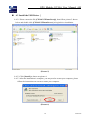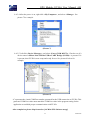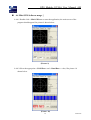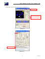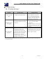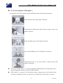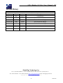
1
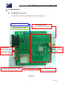
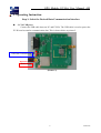
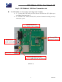
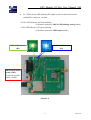
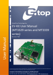
GPS Module EV-Kit User Manual A05
GlobalTop
GPS Module EV-Kit
User Manual A05
1
2012/8/15
GPS Module EV-Kit User Manual A05
Table of Contents
Caution ................................................................................................................................................ 3
Packing ................................................................................................................................................ 3
1. Introduction .................................................................................................................................... 4
2. Specification.................................................................................................................................... 5
2.1 Hardware overview .............................................................................................................. 5
3. Operating Instruction .................................................................................................................... 6
3.1 Via USB port......................................................................................................................... 6
3.2 GPS Module can be tested by connecting to PC via USB................................................. 7
4. Software Usage ............................................................................................................................... 9
4.1 System requirement ............................................................................................................. 9
4.2 Making sure you have the Correct USB Driver ................................................................ 9
4.3 Install the USB Driver ....................................................................................................... 10
4.4 Mini GPS Software usage .................................................................................................. 12
5. Trouble-shooting........................................................................................................................... 14
5.1 Problem with Setup ............................................................................................................ 14
5.2 Concerning Poor GPS Signal ............................................................................................ 15
2
2012/8/15
GPS Module EV-Kit User Manual A05
Caution
Global position system (GPS) is the property of American Ministry of National Defense; they
are fully responsible for the preciseness and maintenance of the system. Any changes they
have implemented to the system in the future may enhance or deteriorate the effectiveness and
performance of the received GPS data.
The GPS signal might be cut-off or become seriously weakened if you operate EV-kit inside
any infrastructures such as buildings, tunnels, or nearby any huge objects and/or obstruction.
The kit has not malfunctioned and will operate properly again once it receives clear GPS
signals (works best under open sky).
To avoid damaging the intricate electronic components and circuitry, please do not place
EV-Kit directly under the sun for long periods of time.
Packing
User Manual / Software Application Program
•
•
CP210X USB Bridge VCP driver
Mini GPS tool with user manual
•
EV-Kit user manual
Note : These information will be delivered by mail. Please contact with your dealer.
USB Cable
EV-Kit with Main Board、GPS Module Board
External Antenna
(Not included PA-Series (PA6B、PA6C), Gms-Series (u5LP) modules.)
3
2012/8/15
GPS Module EV-Kit User Manual A05
1. Introduction
Thank you for purchasing G.top module EV-Kit. The main purpose of this EV-Kit is to
simplify the evaluation process to our GPS modules and to help testers operate our products
with convenience and ease. G.top module EV-Kit is suitable for use in combination with
majority of G.top modules such as: SL-Series (SL2B, SL3, SL3C), PA-Series (PA2, PA4,
PA6B, PA6C, PA6H) and Gmm-Series (u1, u5LP, u5j), Gms-Series (u1LP, u5LP).
This device can communicate with computer devices via USB, and must be used in
conjunction with Mini GPS software application if you wish to record satellites’ signal status,
time-to-first-fix (TTFF), date and time.
Features:
:
For use with SL-Series, PA-Series, and Gmm-Series, Gms-Series modules board.
USB communication port.
External SMA Antenna connector with DC output (optional Models).
Power LED Indicator (Red)
3D Fix LED Indicator (Blue)
1PPS LED Indicator (Green)
4
2012/8/15
GPS Module EV-Kit User Manual A05
2. Specification
2.1 Hardware overview:
:
The EV-Kit’s detail device description is shown below on picture 1
3D-Fix LED Indicator (D2)
GPS Module Board
(SL3C Module in this example)
1PPS LED Indicator (D3)
Main Board
enable switch (SW1)
Control the Main
board enable / disable
USB communication port (USB1)
(For Power input &data transmission)
External SMA
Antenna Connector
(CN2)
Power LED Indicator (D1)
Main Board
(Same with other modules)
(Picture 1)
5
2012/8/15
GPS Module EV-Kit User Manual A05
3. Operating Instruction
Step 1: Select the Desired Data Communication Interface
3.1 Via USB port:
:
Connect the USB cable between PC and EV-Kit. The USB cable is used to power the
EV-Kit and to transfer communication data. This is shown below as picture 2.
USB Data Transmission
Step 2
Step 1
Power Input
(Picture 2)
6
2012/8/15
GPS Module EV-Kit User Manual A05
Step 2: GPS Module & USB Data Transmission test
3.2 GPS Module can be tested by connecting to PC via USB:
:
3.2.1 Connect the USB cable and check Power LED Indicator (D1) lights up or
not. Show below in picture 3.
3.2.2 Switch on the enable switch (SW1) and check module working or not by
Mini GPS system.
GPS Module Board
(SL3C Module in this example)
External SMA
Antenna Connector
Main Board
enable switch (SW1)
USB Cable Connector
Power LED Indicator (D1)
Red LED lights up Power On the device
(Picture 3)
7
2012/8/15
GPS Module EV-Kit User Manual A05
3.2.3 When Power LED Indicator(D1) lights up and on main board enable
switch(SW1) switch on, can find:
--3D Fix LED Indicator (D2) blue blinking
(If firmware parameter 3D-Fix LED blinking setting enable)
--1PPS LED Indicator (D3) green blinking
(If firmware parameter 1PPS output enable)
3D-Fix LED Indicator
1PPS LED Indicator
(D3)
(D2)
Main Board enable
switch (SW1)
Control the module
enable / disable
(Picture 4)
8
2012/8/15
GPS Module EV-Kit User Manual A05
4. Software Usage
4.1 System requirement:
:
PC:IBM, Pentium or above or compatible PC。
Memory:16MB or above。
Display card:VGA compatible
Operation system:Windows 98/Me/2000/2000XP
4.2 Making sure you have the Correct USB Driver:
:
Please double check you have the correct USB driver before you proceed with the next step. If an
incorrect driver is installed, your EV-Kit will not function!
If you have purchased the EV-Kit for use with [SL-Series, PA-Series, and Gmm-Series,
Gms-Series], please make sure you have [CP210xVCPInstaller.zip] installation file in
the package, and proceed to the next section: [4.3 Install the USB Driver].
※If you do not have the correct driver, please download it from our site at
http://www.gtop-tech.com/jsf/download.jsf
9
2012/8/15
GPS Module EV-Kit User Manual A05
4.3 Install the USB Driver:
:
4.3.1 Please extract the file [CP210xVCPInstaller.zip], then follow picture 5 shown
below and double click [CP210xVCPInstaller.exe] to begin driver installation.
(Picture 5)
4.3.2 Click [Install] as shown on picture 6.
4.3.3 After the installation is complete, you may need to restart your computer, please
follow the instructions on screen to restart your computer.
(Picture 6)
10
2012/8/15
GPS Module EV-Kit User Manual A05
4.3.4 After the power is on, right click <My Computer>, and select <Manage>. See
picture 7 for example.
(Picture 7)
4.3.5 Left click <Device Manager>, and select <Ports (COM &LPT)>. Check to see if a
device named <Silicon Labs CP210x USB to UART Bridge (COM#)> is present. If it
is present, then EV-Kit is now setup and ready for use. See picture 8 below for
example.
(Picture 8)
“#”represents the virtual COM Port number generated for the USB connection to EV-Kit. This
generated COM Port value must match the COM Port value in the program setting for the
application to establish proper communication with EV-Kit.
After completion, please skip forward to [4.4 Mini GPS Software usage]
11
2012/8/15
GPS Module EV-Kit User Manual A05
4.4 Mini GPS Software usage:
:
4.4.1 Double click < Mini GPS.exe> to start the application, the main screen of the
program should appear like picture 9 shown below.
(Picture 9)
4.4.2 Select the appropriate <COM Port> and < Baud Rate > value, like picture 10
shown below.
Step 1 Step 2
(Picture 10)
12
2012/8/15
GPS Module EV-Kit User Manual A05
Finally click <open> like the following Figure 11 and Figure 12.
Firmware Version
(Position DOP, PDOP)
(Horizontal DOP, HDOP)
(Vertical DOP, VDOP)
Step 3
(Picture 11)
View NMEA code
(Picture 12)
13
2012/8/15
GPS Module EV-Kit User Manual A05
5.Trouble-shooting
5.1 Problem with Setup:
:
Problem
Cannot find GPS
device
Possible Cause
USB was not setup properly.
Trouble shooting
Check to see if EV-Kit was setup
properly, and make sure that the
device is receiving enough power
through the USB cable (Red LED
should light up continuously).
No NMEA data or
(1) USB was not setup properly.
(2) COM Port or Baud rate value is
incorrect.
GPS signals
Poor GPS Signal
Reception
(1) Check to see if the USB connector
to PC or EV-Kit is tightly
connected.
(2) Double check to see if the proper
COM Port and Baud rate value was
selected.
(1) If it is used inside a vehicle, the
For both problems, please connect the
anti-sunscreen film on the
windshield may interfere and
weaken the GPS signal reception.
(2)When the vehicle is traveling
external antenna to the EV-Kit, and
place the antenna on the roof top to
improve signal reception.
through an area with dense
overhead canopy: such as forest,
buildings, open tunnels etc.
Note: If the above troubleshooting advice does not solve your problems, please send it back to us
for testing and repair.
14
2012/8/15
GPS Module EV-Kit User Manual A05
5.2 Concerning Poor GPS Signal:
:
It is possible to have GPS signal reception difficulties under the following situations:
Inside a tunnel, where GPS signal is blocked.
Underneath an infrastructure (like beneath a bridge), where GPS
signal is blocked.
Inside a building, where GPS signal is blocked.
Next to tall buildings, where GPS signal is weakened.
Underneath forests or any other kinds of canopy where GPS
signal is weakened..
If you use EV-Kit inside a car with anti-sunlight windshield film, the GPS signal will be
severely degraded, and may result in no GPS reception.
GPS satellite is a property of United States Army. Sometimes they will tune-down the
accuracy for unknown reasons. In such cases, the GPS position may not be as accurate.
15
2012/8/15
GPS Module EV-Kit User Manual A05
Version History
History
Date
Rev.
Author
Description
2009/02/04
A01
Ying-jie
First Release
2009/10/08
A02
Eric
Revised for new drivers
2009/11/23
A03
Brian
Revised for new design
2010/01/04
A04
Brian
Revised for new design
2012/05/03
A05
Dylan
Revised for new design
GlobalTop Technology Inc.
No. 16, Nan-Ke 9th Road,
Tel: +886 6 5051268
Science-Based Industrial Park, Tainan 741, Taiwan, R.O.C.
Fax:+886-6-5053381 http://www.gtop-tech.com email: [email protected]
Copyright© 2012 GlobalTop. All rights reserved
16
2012/8/15