1
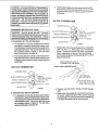
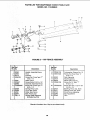
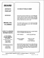
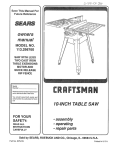
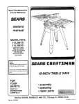
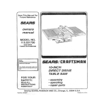
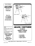
Save This Manual For
Future Reference
MODEL NO.
113=29884
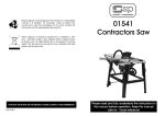
SAW WITH LEGS
TWO CAST IRON
TABLE EXTENSIONS
MOTOR AND
QUICK RELEASE
RIP FENCE
CRRFTSMRH
Sedal
Number
Model and serlQI num_:x_rmay
be fotr_
at 1he rlghf-I'_nd side of the
bose.
You should r_ord both model
and sedal number In a safe
place for future use.
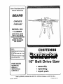
10" Belt Drive Saw
FOR YOUR
SAFETY:
• assembly
= operating
• repair parts
READ ALL
INSTRUCTIONS
CAREFULLY.
_,,
J
Sold by SEARS,
Part No SP5624
J
_.
ROEBUCK
AND CO., Hoffman
Estates,
IL. 60179
U.S.A.
Printed in U S A
BI
if within one year from the data of purchase, this Craftsmen Table Saw fails due to a defect in
WARRANTY SERVICE IS AVAILABLE BY SIMPLY CONTACTING THE NEAREST SEARS SERVICE
CENTER/DEPARTMENT
THROUGHOUT THE UNITED STATES.
THIS WARRANTY
APPLIES ONLY WHRLE THIS PRODUCTIS
USED IN THE UNITED STATES.
This warranty gives you specific legal rights, and you may also have other rights which vary from
state to sttata.
SEARS, ROEBUCK AND CO., D/817 WA Hoffman Estates, iL 60179
SAFETY iNSTRUCTiONS
Safety is a combination of common sense, staying alert
and knowing how your table saw works. Read this
manual to understand this saw.
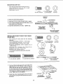
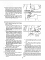
4. GROUND THE SAW- This saw has an approved 3conductor cord and a 3-prong grounding type plug.
The plug fits grounding type outlets designed for 120
volt 15 amp circuits. The green conductor in the cord
isthe groundingwire. To avoid electrocution, NEVER
connect the green wire to a live terminal.
BEFORE USING THE SAW
WARNING: To avoid mistakes that could cause
serious, permanent Injury, do not plug the saw in
until the following steps have been satisfactorily
completed.
5. To avoid injuryfrom electrical shock, make sure your
fingers do not touch the plug's metal prongs when
plugging in or unplugging the saw.
1. Assembly and Alignment (See pages 13 - 34).
6. To avoid back injury, get help or use recommended
casterswhen you need to movethe saw. Always get
help if you need to il_ the saw. Hold the saw close to
yourbody. Bend your knees so you can lift withyour
legs, not your back.
2. Learn the use and function of the ON-OFF Switch,
Guard, Spreader, Anti-Kickback device, MiterGauge,
Fence, Table Insert and Blade Elevation and Bevel
Controls. (See page 35)
3. Review and understanding of all safety instructions
and operating procedures in this manual.
4. Review of the maintenance
7. NEVER STAND ON TOOL. Serious injury could
occur ifthe tool tips or you accidentally hit the cutting
tool. Do not store anything above or near the tool
where anyone might stand on the tool to reach them.
methods for this saw.
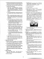
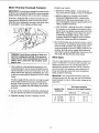
Read theDANGER label found on the front of the saw as
shown below.
BEFORE EACH USE:
1. Inspect your saw.
WHEN INSTALLING OR MOVING THE SAW
1. AVOID DANGEROUS
ENVIRONMENT.
FOR TABLE SAW
A. To avoid injuryfrom accidental starting, unplug the
saw, turnthe switch off and remove the switch key
before raising or removing the Guard, changing
the cutting tool, changing the setup or adjusting
anything.
Use the
saw in a dry place protected from rain. Keep work
area well lighted.
2_To avoid injury from unexpectedsaw movement:
B. Support the saw so the table is level and the saw
does not rock.
B. Check for alignment of moving parts, binding of
moving parts, breakage of parts, mounting, and
any other condit_ns that may affect the way it
works. If any part is missing, bent, or broken in any
way, or any electrical parts don't work properly,
turn the saw off and unplug the saw.
C. Bolt the saw to the floor if it tends to slip walk, or
slide during normal use.
C. Replace damaged, missing, or failed parts before
using the saw again.
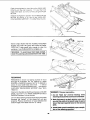
D. When using table extensions over 24 inches wide
on any side of the saw, bolt the saw to the floor or
prop up the outer end of the extension from tLa
floor to keep the saw from tipping.
D. Use the Sawblade Guard, Spreader, and AntiKickback Pawlsfor anythru-sawing (whenever the
blade comes through the top of the workplace).
Make sure the Pawls work properly. Make sure the
Spreader is in line with the sawblade.
A. Put the saw on a firm level surface where there is
3. Put the saw where neither operators nor bystanders
must stand in line with the saw blade.
!
1, Read manual before using saw
I
2. Wear
ANSt
safety goggles
ZE_Trl standards,
3 DO not reach
b_;_des
around
that
4. Keep blade guard down and m
meet
5
Or over
saw
pla_e for through
Do not do freehand
6, Keep h_5
bJade
cbts.
cuts,
out of path
7. When ripping_ use push stickwhen
fence
blade.
of s3w
is set 2 _nc_es
or
g. When ripping,
use push bI_CK ana
aux_Fary
fence when fence
_s set
between
2 and 2 inches
from
blade
Do not make
r_ cu_s
risk of
narrc_ver
tr_an _/_ inch.
for flppli'Ig
more
_DANGER
B. Know how t_ reduce
the
_c_back
See in_ructtons
from
t 0. Turn power
Off and wait
_ stop
befor_
_l_jtJStl_lg
_ervi¢lng
for blade]_
ot
I
E. REMOVEADJUSTING
KEYSANDWRENCHES.
Form habit of checking for and removing keys and
adjusting wrenches from tool before turning it on.
F, To avoid injury from jams, slips or thrown pieces
(kickback and throwback):
1. USE ONLY "RECOMMENDED
ACCESSORIES" (See page 58). Follow the instructions
that come with the accessories.
The use of
improper accessories may cause risk of injury to
persons.
2. Choose the right blade or cutting accessory for
the material and the type of cutting you plan to
do.
3. Never use grinding wheels, abrasive cut-off
wheels, friction wheels (metal slitting blades)
wire wheels or buffing wheel. Theycan fly apart
explosively.
4. Choose and inspect your cutting tool carefully.
a. To avoidcuttingtoolfailure
andthrown shrapnel (broken pieces of blade), use only 10" or
smaller blades or other cutting tools marked
for speeds of 3450 rpm or higher.
1. Do not wear loose clothing, gloves, neckties or
jewelry (rings, wristwatches).
They can get
caught and draw you into moving parts.
2. Wear nonslip footwear.
3. Tie back long hair.
4. Roll long sleeves above the elbow.
5. Noise levels vary widely. To avoid possible
hearing damage, wear ear plugs or muffs when
using saw for long periods of lime.
6. Any power saw can throw foreign objects into
the eyes. This can cause permanent eye
damage. Wear safety goggles (not glasses)
that comply with ANSI Z87.1 (shown on package). Everyday eyeglasses have only impact
resistant lenses. They are not safety glasses.
Safety goggles are available at Sears retail
catalog stores. Glasses or goggles not in compliance with ANSI Z87.1 could seriously hurt
you when they break.
WEAR
YOUR
b. Always use unbroken, balanced blades
designed to fit this saw's 5/8 inch arbor.
c. When thru-sawing (making cuts where the
blade comes through the workpiece top),
always use a 10 inch diameter blade. This
keeps the spreader in closest to the blade.
d. Do not overtighten arbor nut.
wrenches to "snug" it securely.
Use arbor
e. Useonlysharpbladeswith
properly setteeth.
Consult a professional blade sharpenerwhen
in doubt,
f. Keep blades clean of gum and resin.
5. Adjust table inserts flush with the table lop.
NEVER use the saw without the proper insert.
6. Make sure all clamps and locks are tight and no
parts have any excessive play.
2. Keep work area clean
A Cluttered areas and benches invite accidents.
Floor must not be slippery from wax or sawdust.
B. To avoid burns or other fire damage, never use the
saw near flammable liquids, vapors or gases.
C. To avoid injury, don't do layout, assembly, or setup
work on the table while the blade is spinning. It
could cut or throw anything hitting the blade.
Plan ahead to protect your eyes, hands, face,
ears.
3. Plan yourwork
A. USE THE RIGHT TOOL - Don't force tool or
attachment to do a job it was not designed for.
B. Dress for safety:
7. For dusty operations, wear a dust mask along
with the safety goggles.
C. Inspect your workpiece. Make sure there are no
nails or foreign objects in the part of the workpiece
to be cut.
D. Plan your cut to avoid KICKBACKS and THROWBACKS - when a part or all of the workpiece binds
on the blade and is thrown violently back toward
the front of the saw.
1. Nevercut FREEHAND: Always use eithera rip
fence, miter gauge or fixture to position ane
guide the work, so it won't twist bind on the
blade and kickback.
2. Make sure there's no debris between the workpiece and its supports.
3. When cutting irregularly shaped workpieces,
plan your work so it wilt not slip and pinch the
blade:
a. A piece of molding, for example, must _ie flat
or be held by a fixture or jig that will not let it
twist rock or slip while being cut. Use jigs or
fixtures where needed to prevent workpiece
shifting.
b. Use a different, better suited type of tool for
work that can't be made stable.
4. Use extra caution with large, very small
awkward workpieces:
a. Use extra supports (tables,
blocks, etc.] for anyworkpieces
or
saw horses.
large enough
to tip when not held down to the table top.
NEVER use another person as a substitute
for a table extension, oras additional support
for a workpiece that is longer or wider than
the basic saw table, or to help feed, support
or pull the workpiece.
b. Never confine the piece being cut off, that is,
thepieceNOTagainstthe Fence, MiterGauge
or fixture. Never hold it, clamp it, touch it, or
use length stops against it. It must be freeto
move. Ifconfined, itcould get wedged against
the blade and cause a kickback or throwback.
c. Never cut more than one workpiece at atime.
d. Never turn your table saw "ON" before clearing everything except the workpiece and
related support devices off the table.
4. Plan thewayyou
will pushtheworkplecathrough.
A. NEVER pull the workpiece through. Start and
finish the cut from the front of the table saw.
B. NEVER put your fingers or hands in the path of
the sawblade or other cutting tool.
C. NEVER reach Inback ofthe cutUngtool with either
hand to hold clown or support the workpiece,
remove wood scraps, or for any other reason.
D. Avoid hand positions where a sudden slip could
cause fingers or hand to move into a sawblade or
other cutting tool.
E. DON'T OVERREACH.
and balance.
Always keep good footing
F. Push the workpiece against the rotation of the
blade. NEVER feed material into the cutting tool
from the rear of the saw,
G, Always push the workpiece all the way past the
sawblade.
H.As much as possible, keep your face and body to
one side of the sawblade,out of linewith a possible
kickback or throwback.
I. NEVERtumthe saw"ON"before cleadngthetable
of all tools, wood scraps, etc., except the workpiece and related feed or support devices for the
cut planned.
J. AVOID ACCIDENTAL STARTING - Make sure
switch is "OFF" before plugging saw in.
WHENEVER SAW BLADE IS SPINNING
WARNING: Don't let familiarity (gained from frequent use of your table saw) cause a careless
mistake. Always remember that a careless fraction of a second is enough to cause a severe
injury.
1. Before actually cutting with the saw, watch it while it
runs for a short while. If it makes an unfamiliar noise
or vJ_oratesa lot, stop immediately. Turn the saw off.
Unplug the saw. Do not restart until finding and fixing
the problem.
2. Make sure the top of the arbor or cutting toot tu ms
toward the front of the saw.
3. Set the cutting tool as low as possible for the cut
you're planning.
4. KEEP CHILDREN AWAY. Ailvisitors should be kept
asale distancefmmwork. Make sure bystanders are
clear of the saw and workpiece.
5. Let the blade reach full speed before cutting.
6. DON'T FORCE TOOL. It will do the job better and
safer at itsdesigned rate. Feed the workpiece intothe
blade only fast enough to let it cut without bogging
down or binding.
7. Before freeing any jammed material:
A. -rum switch "OFF".
B. Unplug the saw.
C. Wait for all moving parts to stop.
D. Check blade, Spreader and Fence for proper alignment before starting, again.
8. To avoid throwback of cut off pieces;
A. Use the Guard assembly.
B. To remove loose pieces beneath or trapped inside
the guard:
1. Turn saw "OFF".
2. Remove switch key.
3. Wait for blade to stop before liftingthe Guard.
additional
instructions
for
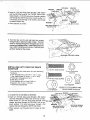
RiP TYPE CUTS
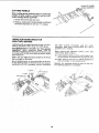
1. NEVER use the Miter Gauge when ripping.
2. Use a Push Stick whenever the fence is 2 or more
inches from the blade. When thru=sawing, use an
Auxiliary Fence and Push Block whenever the Fence
must be between 1/2 and 2 inches ofthe blade. Never
thru-saw ripcuts narrower than 1/2 inch. (See"BASIC
SAW OPERATION - USING THE RiP FENCE" section.)
3. Never rip anything shorter than 10" long.
4. When using a Push Stick or Push Block, the trailing
end of the board must be square. A Push Stick or
Block against an uneven end could slip off or push the
work away from the Fence.
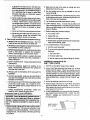
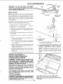
5. A FEATHERSOARD can help guide the workpiece.
See "BASIC SAW OPERATION - USING THE RiP
FENCE." Always use Featherboards for any non
thru rip type cuts.
24"
KERFS ABOUT
5/16" APART
4-112 '' '-'_--'_
5'""
BEFORESTARllNG
1. To avoid kickbacks and slips into the blade, make
sure the Rip Fence is parallel to the sawblade.
2. Before thru-sawing, check the Anti-Kickback Pawls.
(See "BASIC SAW OPERATION - USING THE RIP
FENCE.") The Pawls must stop a kickback once it
has started. Replace or sharpen Anti-Kickback Pawls
when points become due
3. Plastic and composition (like hardboard) materials
may be cut on your saw. However, since these are
usually quite hard and slippery, the Anti-Kickback
Pawls may not stop a kickback. Therefore, be especially careful in your set-up and cutting procedures.
WHILE CUTTING
1. To avoid kickbacks and slips into the blade, always
push forward on the section of the workpiece between
the saw blade and the Rip Fence. Never pushforward
on the piece being cut off.
additional
instructions
for
CROSS CUT TYPE CUTS
BEFORE STARTING
1. NEVER use the Rip Fence when crossc:£ting.
2. An auxiliary wood facing attached to the Miter Gauge
can help prevent workpiece twisting and throwbacks.
Attach it to the holes provided. Make the facing long
enough and big enough to support your work. Make
sure, however, it will not interfere with the Sawblade
Guard.
glossary
3. Use jigs or fixtures to help hold any piece too sina!! to
extend across the full length of the Miter Gauge face
during the cut. This lets you propedy hold the Miter
Gauge and workpiece and helps keep your hands
away from the blade. (See page 37.)
WHgLE CUTTING
1. To avoid blade contact, always hold the Miter Gauge
as shown in the "BASIC SAW OPERATIONS - USiNG THE MITER GAUGE."
BEFORE LEAVDNG THE SAW
1. Turn the saw off.
2.
Wait for blade to stop spinning,
3. Makeworkshopchild-proof.
Lock the shop. Disconnect master switches. Remove the yellow Switch
Key. Store it away from children and others not
qualified to use the tool.
4. Unplug the saw.
SAFETY
SIGNAL
WORDS
DANGER: means if the safety information is not followed, someone wig be seriously injured or killed.
WARNING: means if the safety information is not followed, someone could be seriously injured or killed.
CAUTION: means if the safety information is not fo!lowed, someone might be injured.
of terms for woodworking
Anti-Kickback Pawts {AKP)
Device which, when properly maintained, isdesigned to
stop the workpiece from being kicked back at the operator during dpping operation.
Kerr
The amount of material removed by the blade in a
through cut or the slot produced by the blade in a non
through or partial cut.
Arbor
The shaft on which a cutting tool is mounted.
Kickback
An uncontrolled grabbing and throwing of the workpiece
back toward the front of the saw.
Crosscut
A cutting or shaping operation made across the width of
the workpiece.
Dado
A non through cut which produces a square ._;ided notch
or trough in the workpiece.
Featherboard
A device which can help guide workpieces during rip
type operation.
Freehand
Performing a cut without using a Fence, Miter Gauge,
fixture, hold down or other proper device to keep the
workpiece from twisting during the cut.
Gum
A sticky, sap based residue from wood products.
Heel
Misalignment of the blade.
Leading End
The end of the workpiece which, during a rip type
operation, is pushed into the cutting tool first.
Meldlng
A non through cut which produces a special shape inthe
workpiece used for ioining or decoration.
Push Stick
A device used to feed the workpiece through the saw
during narrow ripping type operations and helps keep
the operator's hands well away from the blade.
Push Block
A device used for rippingtype operations |oo narrow to
allow use of a Push Stick.
Rabbet
A notch in the edge of a workpiece.
Resin
A sticky, sap base substance that has hardened,
glossary of terms for woodworking
Ripping
A cutting operation along the length of the workpiece.
ThrOw-Back
Throwing of pieces in a manner similar to a kickback.
Revolutions Per Minute (RPM)
Thenumber of turns completed by a spinning object in
one minute.
Thru-Sawlng
Any cutting operation where the blade extends completely though the thickness of the workpiece.
Sawblade Path
Theareaof the workpiece or table top directly in line with
the part of the workplece which will be or has been, cut
by the blade.
Set
The distancethat theti 3of the sawblade tooth is bent (or
set) outward from the face of the blade.
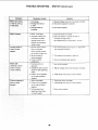
MOTOR SPECiFiCATiONS
MOTOR
SPECIFICAT|ONS
chine or any motor with an automatic reset overprotector.
can blower
start uporbywashing
themselves
t load
WARNING:
Do They
riot use
maand you could get Injured.
TO POWER
SOURCE
This saw must be grounded while in use to protect the
operator from electrical shock.
WARNING:
Damaged power cords can cause
shock or fires, if the power cord is worn, cut or
damaged in any way, have it replaced immediately.
WARNING:
Workpiece
The item on which the cutting operation is being done,
The sudaces of a workpiece are commonly referred to
as faces, ends, and edges.
AND ELECTRICAL
This saw isdesigned to use a 3450 RPM motor only. Do
not use any rnotorthat runs faster than 3450 RPM. The
A-C motor used in this saw isa capacitor start, capacitor
run, non-reversible type motor, it is wired at the factory
for operation on 120v AC, 60 Hz., alternating curre_. It
may be converted to operate on 240v AC. Listed below
are the motor specifications.
CONNECTING
OUTLET
Trailing End
The wod_oiece end last cut by the blade in a ripping
operation.
REQUIREMENTS
WARNING:
To avoid electrical shock, do not
permit fingers to touch the terminals o! the plug,
when installing or removing the plug to or from
the outlet.
WARNING: Failure to properly ground this power
tool can cause electrocution or serious shock,
particularly when used in damp locations, or near
metal plumbing, lifshocked, your reaction could
cause your hands to hit the cutting tool.
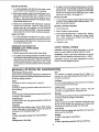
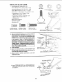
This saw is equipped with a 3-conductor cord and
grounding type plug which has a grounding prong,
approved by UndePJvriter'sLaboratories and Canadian
Standards Association. The ground conductor has a
green lugand is attached to the tool housing at one end
and to the ground prong in the attachment plug at the
other end.
GROUNDING LUG
3-PRONG
¢P;
3-PRONG PLUG
MAKE SURE THIS IS
CONNECTED
TO A
KNOWN GROUND
_ 2-PRONG
RECEPTACLE
Electric shockcan kill. Not all ouUets
are properly grounded, if you are not sure that
your outlet is properly grounded, have it checked
by a qualified electrician.
[ ,ii
ADAPTER
This plug requires a mating 3-conductor grounded type
outlet as shown above.
It is recommended that you have a qualified electrician
replace the TWO prong outlet with a properly grounded
THREE prong outlet.
GROUNDING PRONG
GROUNDED
3-PRONG OUTLET
Atemporary adapter, as shown, is available for connecting plug to 2-prong receptacles. The green grounding
lug extending from the adapter must be connected to a
permanent ground such aslo a properly grounded outlet
box. This adapter should be used only until a properly
grounded outlet can be installed by a qualified electrician.
b. The movable links pivot on the center most screv_,_ After links have been correctly positioned, be SL_r_
to tighten these screws to insure a good etectdc _
connection.
WARNING: Avoid eJectric shock, if the outlet you
are piannlng to use for this saw Is of the two prong
type, DO NOT REMOVE OR ALTER THE GROUNDiNG PRONG IN ANY MANNER. Use an adapter, as
shown, and always connect the grounding lug to
a known ground, such as to a properly grounded
outlet box,
Not aJll o_iet boxes are properly
grounded° If you are not sure the outlet box is
properly grounded, have It checked by a quaJified
electrlclan.
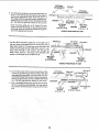
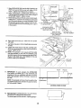
CHANGING
240 VOLT
COPPER
MOTOR VOLTAGE
BLACK POWE
WARNING:
Eiectric shock can kill.To avold
shock, never connect plug to power source outUet
until a_l assembly slops are completed. Unplug
saw before making or changing any connections.
WHITE POWER
SILVER
FIGURE
GROUNDING BLADE tS
LONGEST OF 3 BLADES
24ov PLUG&RECEPTACLE
120 VOLT CONNECTION
BLACK POWER LEAD --n_
....
i '--_ i
#
GROUND SCREW
IN THIS
.LINKS
B
?_
-_..... J
,--
GROUNDED
OUTLET
BOX
GREEN
SPADE
TERMINALS_.
t _
COPPER
POST __-J_"4..\_
2
c. Replace the !20v power cord plug with a (3 blade)
240v 15 Amp U.L listed plug (see illustration
below). Connect the power cord white and black
leads, respectively, to the two "hot" plug blades
and connect the power cord grounding wire to th_
plug ground prong.
b. The movable links pivoton the centermost screws.
After linkshave been correctly positioned, be sure
to tighten these screws to insure a good electricaI
connection.
/r----
E_.W
RED
B
a. For operation on 120 volts, the bRackpower lead is
connected to spade terminal beside copper post.
The white power lead is connected to spade terminal beside silver post. The two movable links must
be in position shown in Figure 1, The red motor
lead is connected to terminal "B."
:OL_ER
LEAD
_i
ER POST
GREEN
GROUND
SCR
IN THIS
POSITION
SPADE TERMINALS,
1. Connections for 120v AC Operation
WHITE
CONNECTION
ADAPTEF{
I S
AVAILABLE
FO F_
THIS TYPE PLUG
RED
POSITION
FIGURE
1
d. Plug yoursaw intoa 240v, 15-Amp, 3-blade receiz_tacle.
2. Connection for 240v AC Operation
e, Make cerlain the receptacle isconnected to a 2 4(3Pv
AC power supply through a 240v branch circ:_ilt
having at least a 15-ampcapacity and protected by
a 15-amp, time-delay fuse or circuit breaker.
a. For operation on 240 volts, the black power lead is
connected to spade terminal beside copper post.
The white power lead isconnected to spade terminal beside silver post. The two movable links must
be in position shown in Figure 2. The red motor
lead is connected to terminal "B."
7
Motor Thermal Overload Protector
breakers may result if:
IMPORTANT: To avoid motor damage, this motor should
be blown out orvacuumed frequently to prevent sawdust
buildup which will interfere with normal motor ventilation.
a. MOTOR IS OVERLOADED - Overloading can
occur if you feed too rapidly or if saw is misaligned
Your saw is equipped with a manual-reset thermal overload protector designed to open the power line circuit
when the motor temperature exceeds a safe level, motor
is overloaded or a low voltage condition exists.
b. MOTOR CIRCUIT IS FUSED DIFFERENTLY
FROM RECOMMENDATIONS - Always follow
instructions for the proper fuse/breaker, Do not
use a fuse/breaker of greater capacity without con.
suiting a qualified electrician
c. LOW VOLTAGE - Although the motor is designed
for operation on the voltage and frequency specified on motor nameplate, normal loads will be handied safety on voltage not more than 10% above
or below the nameplate voltage. Heavy loads.
however, require that voltage at motor terminals
equals the voltage specified on nameplate.
WARNING: Avoid thrown objects or blade con.
tact from unexpected starting, if the protector
stops the saw motor, immediately turn the saw
switch "OFF", remove the key and allow motor
time to cool.
1. After cooling to a safe operating temperature, the
overload protector can be closed manually by pushing the red button on the end of the motor. If the red
button will not click into place immediately, the motor
is still too hot and must be allowed to cool for a while
longer.
The time required for the motor to cool may be equal
to the length of time the saw was used before the
thermal overload protector opened, to shut of! electrical flow, An audible click will indicate the protector
is closed.
2_ As soon as the red button will click into running position. the saw may be started and operated normally.
3. Frequent "blowing" of fuses or tripping of circuit
4. Most motor troubles may be traced to loose or incorrect connections, overloading, reduced input voltage
(such as small size wire in the supply circuit) or to
overly long supply circuit wire. Always check the connections, the load and the supply circuit whenever
motor fails to perform satisfactorily. Check wire sizes
and length with the Wire Size Chart below.
Wire Sizes
The use of any extension cord will cause some loss of
power. To keep this to a minimum and to prevent overheating and motor burn-out, use the table below to
determine the minimum wire size (A.W.G.] extension
cord. Use only 3 wire extension cords which have 3
prong grounding type plugs and 3-pole receptacles
which accept the tools plug.
iMPORTANT: For circuits that are farther away from
electrical service box. the wire size must be increased
proportionately in order to deliver ample voltage to the
saw motor.
Length of the
Conductor
Wire Sizes Required
(American Wire Gage Number)
12(}V Line
240V Line
0 - 25 Feet
26 - 50 Feet
No. 16
No. t4
No. ! 6
No 14
51 - 100 Feet _j.
No. 12
1
No. 12
__j
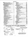
CONTENTS
Warranty ....................................................................
2
Safety instructions for Table Saw .......................... 2
Additional Instructions for Rip Type Cuts ............... 4
Additiona_ Instructions for Cross Cut Type Cuts ...5
Glossary of Terms for Woodworking ..................... 5
Motor Specifications and
Electrical Requirements ...................................... 6
Motor Specifications .............................................
6
Changing Motor Voltage ........................................ 7
Motor Thermal Overload Protector ........................ 8
Wire Sizes ..............................................................
8
Unpacking and Checking Contents ........................ 9
Tools Needed .........................................................
9
List of Loose Pads ............................................... 10
AssembSy ................................................................
13
installing Handwheels .......................................... 13
Checking Table Insed .........................................
13
Checking Blade Squareness to Table ................. 14
Assembling Steel Legs ........................................ 14
Mounting Saw ......................................................
!5
Attaching and Assembling Table Extensions ....... 16
Mounting Switch ..................................................
17
installing Right Front Rip Fence
Guide Bar ........................................................
17
installing Left Front Rip Fence
Guide Bar ........................................................
18
Installing Rear Rip Fence Guide Bars .................. 19
Adjusting Rip Fence Guide Bars .......................... 21
Assembling Rip Fence ......................................... 24
Rip Fence Self Aligning Pad Adjustment ............ 25
Rip Fence Lock Lever Adjustment ....................... 26
Rip Fence Alignment Adjustment ........................ 26
Installing Measuring Tapes .................................. 27
Installing Blade Guard ......................................... 29
Positioning Motor on Motor Mounting Base ......... 31
Mounting the Motor .............................................. 32
Installing Belt Guard ............................................. 33
Motor Connections ............................................... 35
Plugging in Motor ................................................. 35
Getting to Know Your Saw .................................... 36
On-Off Switch .......................................................
36
Elevation Handwheel ........................................... 37
Tilt Handwheel ..................................................... 37
Tilt Lock Handle ................................................... 37
Rip Fence ............................................................. 37
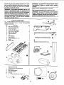
UNPACKING
/_p,
Miter Gauge .........................................................
3-7
BBade Guard .........................................................
37"
"]'able Insert ...........................................................
3"7
Removing and Instal{ing Sawblade .....................
Exact-I-Cut ...................................
Micro-Adjust Rip Fence ....................................... 3._;-_
Basic Saw Operation .............................................
Work Helpers .......................................................
3 g
Push Stick and Push Block .............................. 3_°J
Auxiliary Fence/Work Support ......................... 4.0
Auxiliary Panel/Work Support .......................... z$O
Safety Instructions for Basic Saw Operations ....
Using the Miter Gauge ......................................
Crosscutting .....................................................
Repetitive Cutting ............................................
4_-_
Miter Cutting ....................................................
Bevel Crosscutting ...........................................
Compound Mfter Cutting .................................. 45
Using the R_p Fence ..........................................
Ripping ............................................................
46
Bevel Ripping Narrow Work ............................ 4.6
Using Featherboards for Thru Sawing ............. 4-7
Resawing .........................................................
49
Cutting Panels .................................................
50
Using Featherboards for Non Thru-Sawing ..... 50
Rabbeting ............................................................
5 1
P_oughing and Molding ........................................
53
Dadoing ................................................................
52
Molding Cutting ....................................................
52
Adjustments ...........................................................
Miter Gauge .........................................................
53
Heeling Adjustment or Parallelism of Sawbtade
to Miter Gauge Groove ....................................
55
Blade Tilt, or Squareness of Blade to Table ........ 55
90 ° Position .....................................................
55
45 ° Position ......................................................
56
Tilt Mechanism .....................................................
5-7
Maintenance
...........................................................
57
Lubrication ..............................................................
Recommended Accessories .................................
5_
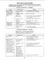
Trouble Shooting ...................................................
59
General ................................................................
59
Motor ....................................................................
59
Repair Parts ............................................................
62
AND CHECKING
COMBINATION
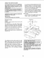
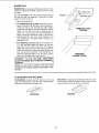
TOOLS NEEDED
CONTENTS
SQUARE MUST BE TRUE
STRAIGHT
EDGE OF BOAF_
3/4" THICK. THIS EDGE MUS*T
BE PERFECTLY
STRAIGH'F.
Screwdrivers
'2',
i_;]l
Pliers
°°
[_RAW LIGHT LINE
ON BOARD
THIS EDGE.
3) Me_lium Phillips
LJ
Combination
Wrenches
3/8
7/16,
SHOULD BE NO GAP OR OVERLAP
HERE WHEN SQUARE IS FLIPPED
OVER IN DOTTED POSITION.
Square
Hex ""L" Wrenches
1/2. 9/16
3132, 1/8, 5132, 3/16
WARNING
8voUChes
Separate all parts from packing materials and check
each one with the illustrationand the list of Loose Parts
use gasoline,
: TO naptha
solvent.
to make certain all items are accounted for, before
discarding any packing matedaL
Apply a,coat of automobile wax to the table.
Wipe atl parts thoroughly with a clean, dry cJoth.
tempt to assemble the table saw or plug in the
cord orIf turn
switch
ur_l! the
j power
WARNING:
any the
parts
am on
missing,
domissing
not atparts are obtained and are Installed correctly.
WARNING: For your own safety, never connect
plug to power source mJtlst u_i! all assembly
steps are complete, and you have read and understand the safety and operating lnstrucUons.
Remove the protective oilthat is applied to the table top
and edges of the table. Use any ordinary household
type grease and spot remover.
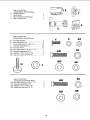
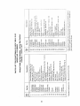
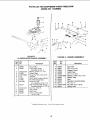
LIST OF LOOSE
ALL ITEMS MARKED WITH
BEEN
DRAWN
FULL
or smmllar
_hhighly
hazard,volatile
never
PARTS
AN ASTERIC
SIZE
FOR
(*) HAVE
EASY
IDENTIFICATION
item
A
B
C
D
E
F
G
H
I
J
K
L
M
Part Name
Miter Gage Assembly
Saw Guard Assembly
Fence Assembly
Front Fence Guide Bar
Rear Fence Guide Bar
Bag of Loose Parts
Owners Manual
Leg
End Stiffener
Side Stiffener
Table Extension 12 x 27
Motor
Fence Tape
Qtv.
1
!
B
2
2
2
1
4
2
2
2
1
2
E
K
•
G
L
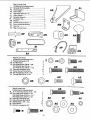
Bag of Loose Parts
(containing the following items)
N
O
Belt Guard
...........
Belt Guard Support
P
Support Bracket .........
L,_ip
.....................
Ty "T" Pan Head Screw, 10-32 x 112
*R
..........
1
1
1
3
3
]0
H
._
?=
S
T
U
V
Bag of Loose Parts
(containing the following items)
Switch Assembly ..........
Hand Wheel ..................
Micro Adjust Knob Assembly .........
Bag of Loose Parts ..............
1
2
1
4
V
©
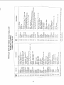
Bag of Loose Parts
(containing the following items)
W
*X
"Y
*Z
*AA
*AB
*AC
*AD
*AE
Z
JUt
Leveling Foot 3/8 ........................................... 4
Hex Jam Nut 3/8-16 ...................................... 8
Truss Head Screw, 1/4-20 x 1/2 .................. 24
External Lockwasher 1/4 .............................. 24
Hex Nut 1/4-20 ............................................ 24
Hex Head Screw, 5/16-18 × 1-t/4 ................. 4
External Lockwasher 5/16 ............................. 4
Washer, 11/32 x 11/16 x 1/16 ....................... 8
Heavy Hex Jam Nut 5/16-18 .......................... 4
X
*AB
*AC
*AD
*AE
Bag of Loose Parts
{containing the following items)
Hex Head Screw, 5/16-18 x 1-1/4
External Lockwasher
5/16
.
Washer 11/32 x 11/16 x 1/16 .....
Heavy Hex Jam Nut 5/16-18
8
8
6
8
AD
11
AE
AF
AG
AH
AI
AJ
AK
*AL
AM
*AN
*AO
AP
AQ
Guard Support ..................................................
Drive Pulley .......................................................
Grip Notch Belt 1/2 x 42 ....................................
Arbor Wrench. ...................................................
Spreader Support .............................................
Protective Cap ...................................................
Bracket ..............................................................
Thumb Screw 5/7 6-18 x 1 .................................
Fence Guide Bar SPacer ..................................
Wire Tie ...........................
Bag of Loose Parts ............................................
i
1
1
1
1
1
4
4
1
6
2
1
AF
LJ
AI
AJ
Z
"AA
"AB
*AC
*AE
"AR
*AS
Bag of Loose Parts
(containing the following items)
External Lockwasher 1/4 .............
Hex Nut1/4-20 .....................
Hex HeadScrew, 5/16-18 x 5/8 ........
Hex Head Screw, 5/16-18 x 1 ..........
Hex Head Screw, 5/16-18 x 1-1/2 ......
External Lockwasher 5/16 ............
Heavy Hex Jam Nut 5/16-18 ...........
Hex Head Screw, 1/4-20 x 518 .........
Carriage BoltS/16-!8 x 3/4 ..........
2
2
2
6
4
16
14
2
4
O
*R
*AB
•AC
"AE
*AT
. AU
*AV
Bag of Loose Parts
(containing the following items)
Ty "T" Pan Head Screw, 10-32 x 3/8
Hex Head Screw, 5/16-!8 x 3/4 .......
Hex Head Screw, 5/16-18 x 1-1/4 ......
Hex Head Screw, 5/16-18 x 5/8 ........
External Lockwasher 5/16
..........
Heavy Hex Jam Nut 5!16-18 ...........
Washer21/_4 × 5/8 x 1t16 ............
Shim Washer .....................
External Lockwasher #10 ............
AB
_.
2
6
2
3
8
8
16
10
2
12
AC
AT
AV
Au
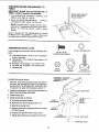
ASSEMBLY
Before mounting the saw on legs or a stand or a bench,
the Table Insert and Blade Squareness must be checked
at this time.
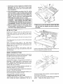
UNSTALLING
HANDWHEELS
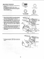
1. Slide theelevation handwheel onto itsshaft. Line
up the fiat spot on the shaft with the set screw in
the handwheeL Using a hex "L" wrench - tighten
the set screw securely against the flat spot on the
shaft. Repeat this same procedure to install the
tilt handwheel.
ELEVATION
HANDWHEEI
TILT HANDWHEEEL
make sure switch is "OFF" and plug is not conJ WARNING: To avoid injury from accideltlai start,
nected to power source ouUet.
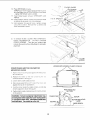
CHECKING
TABLE iNSERT
!. Insert should be flush with table top. Check as shown.
Loosen flat head screw that holds insert and adjust
the four set screws as necessary. Tighten flat head
screw. Do not tighten screw to the point where it
deflects the insert.
3/32 IN.
SET SCREW WRENCH
CAUTION: Insert must be even with the table I
surface,
inserts too high or low can let the I
workplece "snag" or catch on uneven edges. ]
Workplece could twist and kick back°
2. To remove insert.
A. Make sure saw is off and unplugged.
B. Loosen screw.
C. Lift Insert from front end, and pufftoward front of
\
saw.
3. To replace Insert.
A. Make sure saw is off and unplugged.
B. Place Insert into insert opening in table arid push
toward rear of saw to engage spring clip and urltil
keyslot in Insert will drop over screw. Tighten
PHILLIPS
FLAT HEAD
_-- SCREW
screw,
C. Do not tighten screw to the point where it wifl
deflect the Insert.
13
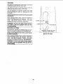
CHECKING
TABLE
BLADE
SQUARENESS
TO
IMPORTANT: BLADE must be SQUARE {90 °) to
TABLE, in order to proceed wilh assembly,
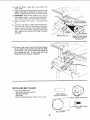
1. Turn ELEVATION
handwheel clockwise
blade is up as high as it will go.
MAKE SURE SQUARE
!S NOT TOUCHING
TIP OF TOOTH
unti!
/
2. Check for BLADE SQUARENESS
_. if blade is
not square to table, adjust it at this time.
NOTE: The combination square must be "true" see start of "Unpacking and Checking Contents"
section for checking method used to check
sq LJare
Refer to "BLADE TET, OR SQUARENESS OF BLADE
TO TABLE" in the "'ADJUSTMENT" section of this manual
for instructions on how to sauare blade to table.
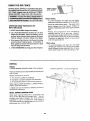
ASSEMBLING
STEEL
©
LEGS
1/4 IN. LOCKWASHER
From among the loose parts, find the following Hardware:
1/4-20 x 1/2 IN.
TRUSS HEAD SCREW
24 Truss Head Screws, 1/4-20 x 1/2 in. long (top of
screw is rounded)
24 Lockwashers, 1/4 in. External Type (approx. dia.
of hole 1/4 in.)
24 Hex Nuts, 1/4-20 (approx. dia. of hole 1/4 in.)
8 Hex Nuts, 3/8-16 (approx. dia. of hole 3/8 in.)
4 Leveling Feet
Q
1/4-20
HEX NUT
3/8-16
HEX NUT
LEVELING FEET
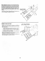
Assemble the legs as shown:
1 Insert the Truss Head Screws through the holes in
the legs, then through the holes in the stiffeners.
MAKE SURE THE SCREWS GO THROUGH THE
HOLES IN THE SIDE STIFFENERS MAKED "X".
2. Install the Iockwashers. Screw onthe nuts but do not
tighten until completely assembled.
3. Install leveling feet.
4. Adjust leveling feet as follows:
1/4-20 x 1/2 IN.
_ TRUSS
HEAD
E.o l
A. Move saw to desired location.
B. With 9/16 inch wrench loosen bottom nut.
STIFFENER F"
i SCREW
C. Back off top nut by hand.
D. Raise or lower foot by adjusting bottom nut using
9!16 inch wrench.
E. Snug top nut against inside of leg by hand.
1/4 IN.
F. Tighten all fourbottom nuts using 9/16 inchwrench,
LOCKWASHER,
14
_,,.
3/8 IN. HEX NUTS
_--
LEVELING
FOOT
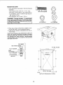
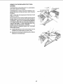
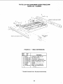
MOUNTING
SAW
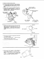
1. From among the loose parts, find the following
hardware:
4 Hex Head Screws, 5/16-18 x 1-1/4 in. long.
_N
HEX HEAD SCREW
5/16 - 18
HEX NUT
4 Hex Nuts, 5/16-18 (approx. dia. of hole 5/16 in.)
4 Lockwashers, 5/16 in. External Type (approx.
dia. of hole, 5/16 in.)
8 Flat Washers, (dia. of hole !1/32 in.)
WARNING:
The saw is heavy. To avoid back
injury, get help to rift the saw. Hold the saw close
to your body. Bend your knees so you can li_twith
your legs, not your back.
5/16 IN
LOCKWASHER
11/32 IN
FLAT WASHER
2. Place saw on legs so that holes in bottom of saw
line up with holes in top of assembled leg set.
3. Install screws, washers, Iockwashers and nuts as
shown below.
If you mount the saw on any other bench, make sure
there is an opening in the top of the bench the same
size as the opening in the bottom of the saw so that
the sawdust can drop through.
Recommended
working height is 33 to 37 inches from the top of the
saw table to the floor.
/
SAW BASE
7/16 DIA. HOLES
FLAT WASHER
END
11-1/4
l
STIFFENER--_I
LOCKWASHER
_
...'
_
/_m==_
l!
'_L_PENIN?/
HEXNUT
13
\
16
13
\/
°
/
/
\
/
\
/
Q
Y
\
!
i
2-3/4
--RONT OF SAW
NOTE: All dimensions
15
__ 1/2
in inches
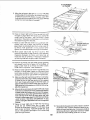
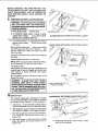
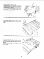
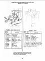
ATTACHING
AND ASSEMBLING
TABLE EXTENSIONS
HEY, HEAD SCREW
From among the loose parts find the following
hardware: (Quantity indicated is for 2 extensions)
Description
Hex Hal. Screw
5/16-18 x 1-1/4
......
Flat Washer (Dia of Hole 11/32)
.....
External
Lockwasher
5/16 ...........
Hex Nut, 5/16-18
....................
Qty.
8
8
8
8
FLAT WASHER
5/16 IN HEX NUT
5/16 IN EX-FERNAL
1. Insert four (4) 5/16-18 x 1-1/4 in. long screws
through holes in each EXTEN SION.
2. Position an extension against table
extend th rough holes in table.
3. Install flat washer, Iockwashers,
screws, ,. DO NOT TIGHTEN,
so screws
/
/
and nuts on the
\--1
HEX HD. SCREW
"-
"_<L
_G
--
-
SAW
>
TABLE
(REF}
FLAT WASHER //
/ '"
EXTERNAL
HEX NUT
LOCKWASHER
4. Une up rearedge of extension with rear edge oftable.
Line up top surface of extension with top surface of
table at the locations indicated by the "X's" (see
illustration).
Use a combination square to line up these edges and
surfaces. Slightly tighten nuts with a 1/2" wrench.
CHECK WITH SQUARE
AT 2 PLACES
MARKED WITH "X"
5. If adjustment is necessary you should tap the
extension into position using a hammer and a
block of wood. Make surerear edge of exten sion
is lined up with rear edge of tab{e. Then firmly
tighten nuts
6. Repeat the same procedure
extension.
BLOCK OF WOOD
to install the other
16
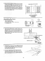
MOUNTING
SWITCH
1, From among loose parts find the following:
2 Hex Head Screws, 5/16-18 x 5/8 in. long
2 External 5/!6" Lockwashers
2 Hex Nuts, 5/t6-18
5/8 IN
HEX HD SCREW
5/t6 IN EXTERNAL
LOCKWASHER
5/16 IN
HEX NUT
i
JAM NUT
5/16-18
,]
2. Select one front fence guide bar.
3. insert two 5/8 inch screws through holes in switch.
,_, _Q/LOCKWASHER
4TH HOLE
! "
5TH HOLE
4. Insert screws through fourth and fifth holes in front
fence guide bar as illustrated.
=
=
"_=.
• .== =----,_
%
5. _nstall two Iockwashers and nuts. Tighten nuts.
FRONT FENCE
GUIDE BAR
(UPSIDE DOWN)
\_\
"_
_
_
HEX HEAD SCREW
5/1 18 x 5/8iN.
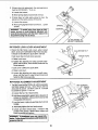
iNSTALLiNG
GUIDE BAR
RIGHT
FRONT
RiP FENCE
1. From among the loose parts find the following
hardware:
2 Hex Head Screws, 5/16-18 x 1-1/2 in. long
1 Hex Head Screw, 5/16-18 x 1-1/4 in. long
2 Hex Head Screws, 5/16-18 x 3/4 in. long
5 External Lockwashers, 5/16 in. (approx. dia. of
hole 5/16 in.)
5 Hex Nuts, 5/16-18 (approx. dia. of hole 5/t6 in.)
3 Spacers, 3/4 in. dia. x 1/2 in. long
5 Washers (dia. of hole 21/64 in.)
1 Front Fence Guide Bar (with switch attached)
2 Brackets
3/4 IN HEX HD.
SCREW
5/16 IN EXTERNAL
LOCK WASHER
5/16 IN
HEX NUT
1/2 IN SPACER
BRACKET
21/64 iN WASHER
1-1/2 IN HEX HD. SCREW
1-1/4 IN HEX HD. SCREW
FENCE GUIDE BAR
WITH SWITCH
2. Put one of the brackets against the right edge of the
right extension so the bracket is lined up with the
FIRST hole near the front of the extension. Insert a
3/4 inch long screw through a flat washer, through
top hote in the bracket, and through the FIRST hole
in the extension, install a Iockwasher and nut on the
screw. Tighten the nut only slightly.
HEX NUT
3. Install the other bracket against the left side of
left extension-using the same procedure explained above.
EXTERNAL
LOCKWASHER
17
HEX HEAD
SCREW
5/16-18 x 3/4 iN
6TH HOLE
4. Insert a 1-114 inch long screw through a flat washer
_-'_-_,
and the SECOND hole IN THE FRONT BAR as illus- _-_
trated, insert a 1-I/4 nch ong screw throuah a washer "_,_;_
and through the SIXTH hole in bar. nsert another 1-1I
"
',,y3_'_ _'1
•
2 Inch long screw through a flat washer and through
the NINTH hold in bar.
Place
p ce,s
onscrews
_ .....
-"
/
SPACER
-_._t_--_
_ "%'---,_:_!'_
_
- _';v_""
_
_
", ; ;itS%,.
_-
- ......
&
_"
/
, ,_ _':
,SHE
-J _
.-,
\
HEX HEAD SCREW "N-_.
5/16-18 X 1-114
_,z
_"_"_
@_
/,
i,_ /
,HEX HEAD
[
y"
6. Turn front bar end for end and insert two screws
through hoaes in right tront edge of table. The third
screw is inserted through the elongated slot in the
bracket you installed earlier. Instafl Iockwashers and
nuts. DON'TSCREW NUTS ON ALL THE WAY, just
get them started on the screws.
iNSTALLiNG
GUIDE BAR
LEFT FRONT
RiP FENCE
1-1/2 IN HEX HEAD SCREW
5/16 IN EXTERNAL
1. From among the loose parts find the following
hardware:
2 Hex Head Screws. 5/16-18 x 1-1/2 in. long
1 Hex Head Screw, 5/16-18 x 1-1/4 in_ long
3 External Lockwashers 5/16 in.
3 Hex Nuts. 5/16-18
3 Flat Washers {dia. of hole 21/64 in.)
3 Spacers, 3/4 in. dia. x 1/2 long
1 Front Fence Guide Bar
1-1/4 tNHEXHEADSCREW
1/2 IN SPACER
2ND
•
2. Lay gu de bar on saw table as illustrated
SPACER /
WASHER
__)
]
5/t6-18
HEXNUT
FLAT WASHER
_
_,J
L-_--_ ............................
_-_
FRONT FENCE GUIDE BAR
HOLE
SPAC_ER
.........
_"
......
6TH HOLE
_'-
3. Insert a !-1'2 inch long screw through a flat washer
_L_I_
"_"
s;--z::.-:__'_"_1and then through the FIRST hole in the bar as illus..
_
trated Insert a 1-112 _nch long screw through a flat ,_,-u,-,LE_._
--_._=_,._:_--, <-....
_ _:.,,
washer and then through the SECOND hole in bar.
_",_:¢'_.,r_'_
./".
._'X,
.
,_,L.-:_---..
"_-_
.._c-_
......- _ \
Insert another 1:1t4 ,nch tong screw through a flat
WASHER-_i
'-_"
-- .... '
HEX HEAD SCREW
washer and then through the SIXTH hole in bar.
HEX HEAD SCREW
J5/16-18 X 1-1/4 _N
4. Place spacers over threaded end of screw as illus5/16-18 X 1-1/2 IN ....
trated.
/ ,
/
18
_.
.
5. Turn front bar end for end and insert two of the
bolts through holes on teft side of front edge on saw
table. The third screw is inserted through the bracket
installed earlier
6. Install lockwashers and nuts on bolts. DO NOT
SCREW NUTS ON ALL THE WAY,just get them started
on the screws.
SCREWS LOCATED
HERE
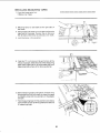
iNSTALLING
REAR FENCE
GUIDE
BARS
1. From among the loose parts find the following:
2 Brackets
4 Hex Head Screws 5/16-18 x 1 in. long
4 Hex Head Screws 5/16-18 x 3/4 in. long
8 Flat Washers (dia. of hole 21/64 in.)
8 External Lockwashers, 5/16 in.
8 Hex Nuts, 5/16-18
2 Rear Fence Guide Bars
4 Protective Caps
5/16-18 x 3/4
HEX HEAD
SCREW
FLAT WASHER
REAR FENCE GUIDE BAR
5/t 6 IN
EXTERNAL
LOCKWASHER
5/16-18 x 1 IN
HEX HD. SCREW
5/16-18
HEX NUT
PROTECTIVE
BRACKET
2. Put one of the brackets against the right rear
edge of the right extension so the bracket is lined
up with the FOURTH hole near the rear of the
extension (see illustration).
CAP
REAR
OF
3. Insert one of the 3/4 inch long screws through a flat
washer, through the bracket, and through the
FOURTH hole in the extension. Install a Iockwasher
and nut on the screw. Tighten the nut only slightly
4. Install the other bracket against the left side of
the left extension using the same procedure
explained above.
EXTERNAL
LOCKWASHER
2ND HOLE
5. Layone rearfenceguidebarontheleft
rearsideofthe
saw table as illustrated (as viewed from rear of the
saw). Insert a I inch long screw through a flat washer
and throughthe SECOND hole of the rear fence guide
bar. Insert a 1 inch long screw through a flat washer
andthroughthe FOURTH hold. Insert a3t4 inch long
screw through a flat washer and through the
ELEVENTH hole.
5/16-18x3/4
HEX HEAD
SCREW
tlTH
4TH HOLE
HOLE
WASHER
WASHER
HEX HEAD
SCREW
5/15-18 X 1 IN
BACK OF SAW
19
l
HEX HEAD
SCREW
5,'16-18X 3/4 IN
EXTERNAL
LOCKWASHER
6. Turnthefenceguidebarendforendandinserttwo
ofthe 1inchlongscrewsthroughthetwoholesin
theleftrearedgeofthe table.Inserttheother3/4
inchlongscrewthroughthebracket.Installa lockwasherandnutonbolts.DONOTSCREW
NUTSON
ALLTHEWAY,
justgetthemstartedonthescrews.
Pushthe fenceguidebar as fartowardthe rear
centerofthesawasitwillgo.It mustremainasclose
totherearcenterofthesawaspossible
througt_
the
restofthisadjusting
procedure,
HEXNUT\_.
_
_WASHER .-"-'__'
,f_
\__
_
LEFT REAR
GUIDE BAR
REXHEAD
SCREW
5/16-18 x 3/4 iN
/
,
-
o
"_
\ .,/WASHER
_'
_"
/ %_..._%'
HE×HEAD
WASHER
SCREW
5/16-18 x 1 iN
VIEWED FROM REAR OF SAW
7. Lay the other rear fence guide bar on the right rear of
2ND HOLE
the saw tabel as illustrated (view is shown from rear of
tabe saw
"
). Insert a 3/4 inch long screw through a flat
washer and through the SECOND hole. Insert a I inch
long screw through a flat washer and through the
NINTH hoe nsert a 1 inch long screw thiough a fiat
washer and through the ELEVENTH hole
•
H_x_T
9TH HOLE
_-iI_-_
.......
_T_
=_ _-F_
- =- _ ::--= _
..... _;,_,JZ - ---_-_ i -_-,:.
:,_?_'-_----_-3i:_-_
_ WASHL_ _'F'_,)
_-_
HE×
HEAD
SCREW
5/16-18 X 3/4 IN
11TH HOLE
:I_
-_---_
-_
_ ..::=_'_F-c,_,,
_ ____.Z_
_) WASHER
t.,Aeu=_
/
I
\ /
_k \
/ _
^ H_u
SCREW
5/16-18 X 1 IN
VIEWED FROM REAR OF SAW
8 Turn the fence bar end for end and insert two ofthe
1 inch long screws through the two holes in the right
rear edge of the saw table. Insert the other 3/4 inch
long screwthrough the bracket. Install a iockwasher
and nut on the screws. DO NOT SCREW NUTS ON
ALL THE WAY,just get them started on the screw.
HEX NUT
EXTERNAL
LOCK WASHER . HEjX_NUT LOCKWASHER_
WASHER _"
9. Push a protective cap over the exposed end of all four
(4) fence guide bars as illustrated. You may' want to
secure these to the fence bars using household type
glue,
_:
t
_'/
HEX HEAD
SCREW
5/16-18 x 1 IN
2O
. ._-: ;:-;.
,--_-_J
o-
9
T
/
/ PROTECTIVE
HEX HEAD
SCREW
CAP
5/16-18 x 3/4 IN.
ADJUSTING
WARNING:
RIP FENCE
Mlsadjusted
GUIDE
BARS
ience guSde bars can
mBsalig n the fence. A misaglgned
fence can cause
kickbacks
and jams.
You could be cut or hit.
Proper_y adjust fence guide bars before
1. From among the loose parts find the following
ware:
using
hardVERY THIN SHIM WASHER
10 each very thin shim washers
2. Move the two front fence guide bars toward each
other until their ends touch. Using a 1/2 inch
wrench tighten the four nuts and bolts that pass
through saw table to hotd guide bars in place.
(Do not tighten the two bolts that pass through
the brackets.)
THESE
_i!]
BOLTS
!! "_'
VIEW FROM TOP OF SAW
3. Check the rounded front edges of rip fence guide
bars to see if they are even with each other, tf they
are even, go on to step 5. If they are uneven (offset
from each other) find the very thin shim washers.
Begin stacking these washers against rounded front
edge of the guide bar whose rounded edge is farthest away from the operator. Continue stacking
washers until the top of the stack is even with round
front edge of the other guide bar. Count the number
of washers in the stack and make two stacks containing this number of washers.
VIEW FROM TOP OF SAW
_-_=_
J
_
/
\_
X=
I
"
o
'
STACK OF
.005 THICK
FLAT WASHER
21
!
/
VIEW FROM TOP OF SAW
4. The guide bar you stacked
washers
against
n
step 3 must now be removed
so stacks of washers
can be installed.
To do
so remove
nuts and
Iockwashers
from tWO screws
that hold the guide
bar to front edge of table.
Pull
guide
bar away
from table and put one stack
of washers on each
bolt between spacerand
front
edge
of table - see
illustration.
Put guide bar back
in place on front
of table and reinstall
[ockwashers
and nuts on
two bolts - do not tighten
at th is time
©
HEX
NUT
TABLE
EXTERNAL
;HER
STACK
OF
WASHERS
SPACER
5. Any of the six (6) screws holding
rip fence guide bars in place,
tightened
us=ng a wrench_ must
and retightened so they are only
the two t21 front
that were earlier
now be loosened
hand tight
OF PAPER
Position rip fence over the right miter gauge
groove. While holding up rear end of Np fence.
engage front end of rip fence
onto r=p fence
guide bar. Now lower rip fence
down onto table
t
6. Cut up a piece of newspaper
in to 16 equally s=zed
pieces about 4 inches square.
Separate these
pieces into two stacks containing
8 p_eces m
each stack. P.ut one stack under rear end of rIp
fence and other stack under front end of rip fence
- see illustration.
7: Raise or lower left end of right
front rip fence
guide bar just enough to aliov_ paper stack (at
front of rip fence) to slide back and forth under
rip fence. Keep guide bar in this position and
tighten screw at the far left of this guide bar.
8. Pushthe left rear (as viewed from
will go. Raise or lower right end
PAPER SHOI
SLIDE EASILY
PAPER STACK
rear of saw) fence
of left rear rip fence
allow stack of paper(at rear of fence) to slide back
and forth under the rip fence. Hold guide bar in this
position and tighten screw at far right of this guide
bar.
SCREW AT
FAR LEFT END
OF RIGHT FRONT
GUIDE BAR
22
8 THICKNESS
OF PAPER
\
9. Move the rip fence to the right so it is even with the
outside edge of the extension (as viewed from front
of saw) and put the two stacks of paper under the
front and rear of the rip fence with the paper setting
on the front and rear edge of the table_
\
\
\
\
\
\
10. Raise or lower right end of front guide bar just
enough so paper stack will slide back and forth
under front of rip fence-see
illustration
Hold
guide barin this position and tighten both screws
that pass through
the brackeL
\
\.
\\
11. Raise or lower left end of left rear guide bar (as
viewed from rear of saw) just enough
to allow
paper stack to slide back and forth under rear of
rip fence. Hold guide bar in this position
and
tighten both screws that pass through the bracket.
PAPER SHOULD
SLIDE EASILY
ADJUST THESE
SCREWS
12. Move paper stack and rip fence
back to the
position
explained
in step 5 above, and recheck
clearance
between
rip fence
and table top at
front and rear of rip fence. If necessary
readjust
rip fence guide bars to get proper clearance.
13. Position rip fence over left miter gauge groove
(as viewed from front of saw). Put one stack of
paper under front of rip fence and other stack
under rear of rip fence - see illustration.
14. Raise or lower right end of left front guide bar just
enough to allow paper stack to slide back and
forth under rip fence. Hold fence in this position
and tighten bolt at far right of left front guide bar.
15. Make sure the right rear fence guide bar is correctly
positioned from left to right. Refer to Page 20. Raise
or lower left end of right rear guide bar (as viewed
from rear of saw) just enough to allow the stack of
paper to slide back and forth under rear of rip fence.
Hold guide bar in this position and tighten bolt at far
left end of guide bar.
16. Move rip fence and stacks of paper to left side of left
extension (as viewed from front.) Position the stacks
of paper under the rip fence and on top of the extensions just as you did on the right extension. Raise or
lower left end of left front rip fence guide bar just
enough to allow paper stack to slide back and forth
under rip fence. Hold fence and guide bar in this
position and tighten both bolts that pass through the
bracket.
17. Raise or lower right end of right rear rip fence
guide bar (as viewed from rear of saw) just
enough to allow stack of paper to slide back an d
forth under rip fence. Hold the guide bar and
fence in this position and tighten both bolts that
pass through bracket.
18. Move stacks of paper and rip fence back to !3osition
explained in step 13 above. Recheck clearance between rip fence and table top. If necessary readjus!
rip fence guide bars to get proper clearance, Tighten
all bolts and nuts holding guide bars in place.
23
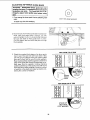
19. Using a tape rule measure distances from rear cage
of back rip fence guide bars to front edge of lront rip
fence guide bars. Make measurements at each miter
gauge grooveand at the end of each extension. A!I
tour measurements must be the same. If adiustment
is necessary loosen bolt that passes through bracket
and extension. Now move the front bar until distance
is correct and retighten bolt.
VIEW FROM TOP OF SAW
t,
t
t
t
SAME MEASUREMENT
AT EACH SET
OF ARROWS
Assembling
Rip Fence
1. From loose parts find:
1 Micro Adjust Assembly
2 Pan Head Screws. 10-32 x 1/2 in. long
2 Lockwashers #10
LOCKWASHER
MICRO ADJUST
ASSEMBLY
;
_!
PAN HEAD
SC REW
2.
adjust assembly on rip fence head as illustrated and
install two 10-32 x 1/2 pan head self tapping screws
through
two lockwashers
holes inmicro
micro
Turn rip fence
upside downandonthrough
table. Position
adjust assembly. Screw into holes in rip fence head
Jlq!llI:-
Tighten both screws.
_,__S_
....,,
_]
J
__
_ i
.... 1," ,
,,
LOCKWASHERS"----_
UPSIDE DOWN RIP FENCE
PAN HEAD
SCREWS
3. Install rip fence on saw. Do so by ho_ing up rear end
of rip fence while engaging rip fence head onto front
rip fence guide rail. Now lower rear end of rip fence
onto back rip fence guide bar.
4. Push micro adjust knob toward rear of saw and
rotate knob. This should cause rip fence to move
dght or left depending on which way you rotate the
knob. tf fence does not move, make this adjustment.
24
A. Adjusting Fence Racks
1. Look under front fer_ce guide bars. The racks
should be approximately 1-1/8 inch apa_
between the ends of both racks as ilJustrated.
2. Adjust the racks by loosening t he lout screws
that mount each rack. Stide both racks to the
1-1/8 inch measurement and tighten all
screws.
B. Adjusting Micro Adjust Cam
Look under rip fence head and find micro-adjust
gearand rack. Teeth on this gear must mesh with
teeth on the rack. Using a 1/8" Hex "L" wrer_h
loosen set screw "A". Now rotate micro-adjust
cam until gear can be pushed underneath teeth
on rack. Line up teeth on rack with the middle of
the gear. Hold gear in this position and rotate
micro-adjust cam until the gear is raised up and
meshes with teeth on the rack. Tighten set screw
SET SCREW "B"
RACK
C. If you were unable to line up the teeth on the rack
with the middle of the gear, then another adjustment is required:
1. Push knob intoward rear of saw and hold knob
MICRO ADJUST
SET SCR EwW"A'_
in this position.
2. Using a Hex "L" wrench, loosen set screw "B".
3. Move gear straight backward or straight forward until teeth on the rack are positioned
in
the middle of the gear. (DO NOT ROTATE
GEAR.)
4. While holding the gear in this position, push
micro-adjust knob all the way in toward the
gear and tighten set screw "B".
RiP FENCE SELF ALIGNING
ADJUSTMENT
PAD
backs and jams. To avoid injury, follow these
I WARNING: A mlsallgned fence can cause kickinstructions until the fence properly self aligns.
1. Check the fence to be sure it slides easily aioP.g the
bars and always remains in alignmenl (parallel to
sawblade and miter gauge grooves).
The alignment is maintained by a spring underneath
the fence which presses against the front guide ba r.
2. To see ifre nce needs adjustment place fence on saw
but DO NOT LOCK IT.
Move the REAR END of the fence slightly to the right
or left...when you release it, the fence should"sprir_jback to its original position.
25
CAM
3. If fence does not spring back, the spring pressure
must be INCREASED. To do so:
A. Loosen the screws.
B. Move spring slightly toward front of fence.
4, If fence does not slide easily along the bars the
pressure of the spring can be REDUCED.
A. Loosen the screws,
B. Move spring slightlytoward rearof fe nce...tighten
SPR ING
screws.
SCREWS
WARNING: To avoid Injury from jams or kickbacks, be sure to push properly adjusted lock
lever allthe way down until the lever rests on the
stop before using this rip fence.
SLIDE SPRING TO
ADJUST PRESSURE
RIP FENCE
LOCK
LEVER
ADJUSTMENT
1. Check the Rip Fence Lock Lever, when locked
down, to be sure it will hold the Rip Fence securely.
It should not be difficult to push down and lock.
_._%_.__
ADJUSTING
NUT
If lock lever does not lock fence securely:
A. Raise Lock Lever.
B, Tighten the adjusting nut using a small screwdriver until the lever, when locked, holds the Rip
Fence securely,
If Lock Lever is difficult to push down:
A, Raise Lock Lever.
B. Loosen the adjusting nut using a small screwdriver unti! the lever is easy to push down and
holds the Rip Fence securely.
RiP FENCE
ALIGNMENT
ADJUSTMENT
1. The RipFence must be PARALLELwith the sawblade
and Miter Gauge Grooves. Move Fence until it is
along side of groove. DO NOT LOCK IT. It should
be parallel to groove, if it is not:
HEX SCREWS
FENCE
HEAD
A. Loosen the two Hex Head Screws.
B. Hold fence head tightly against bar in direction of
arrows on illustration, Move end of fence sothat
it is parallel with Groove.
C. Lock the fence in place by pushing down on lock
handle.
D. Altematelytighten
the hex head screws.
E, Unlock and then re4ock fence. If fence is not
parallel with groove, repeat above steps until
fence is parallel with groove.
WARNING:
A misaUgned fence can cause kick-"l"
backs. Followtheseinstructions
properly aligned,
untilthefence
is I
l
26
mNSTALLmNG MEASURING
TAPES
-"-:-
1. From the !oose parts find:
2 Measuring Tapes
- ......
_
+
4
_ ÷:-÷-4-_t=::T:=F._T-_-_
)
2. Place rip fence on saw table to the right side of
the blade.
3. Using a tape ruie measure six inches out from the
right side of the btade. Position the rip fence so
the left side of the fence is at this six inch mark.
4. Lock
the fence
in this position.
5. Find the "0" inch mark on the end of one of the
measuring tapes, Slide this end of the measuring
tape under right side of rip fence head and push
tape along top surface of rip fence guide bar.
6. Move measuring tape under plastic window of rip
fence head until six inch mark on measuring tape
is straight under red line (pointer) on the plastic
window.
6"MARK
7. Hold measuring tape in this position and draw a
pencil mark across rip fence guide bar at left en0
of measuring tape,
27
o
8. Remove rip fence from saw. Remove measuring
tapefrom
saw but keep it separate from other
measuring tape. It must later be attached to this
same rip fence guide bar. At the left end and rig ht
end of right rip fence guide bar. measure back
3/8" from the front rounded edge and put pencil
marks on the guide bar at these points, Using a
straight edge draw a pencil line that passes
through both of these points.
3/8 INCH FROM
ROUNDED EDGE
9. Repeat this same operation on left front ri p fence
guide bar so it also has a straight pencil line
drawn along its full length and 3/8" back from the
rounded front edge of the guide bar._
10. Find the measuring tape you set aside earlier. It
must be attached to the right front np fence
guide bar. To do so:
A. Find the end of measuring tape with "0" inch
mark. Place this end of measunng tape on
pencil mark you drew across left end of guide
bar earlier. Now place front edge of measunng
tape on line you drew along full length of
guide bar earlier,
B. While holding measuring tape in this position
pick up left end of measu ring tape and peel off
about six inches of protective coating from
underside of measuring tape. This wilt expose
adhesive on underside of measuring tape.
Very carefully lower left end of measuring tape
back down on rip fence guide bar making su re
the measunng tape is lined up properly with
pencil marks. Press left end of measuring tape
down against guide bar so adhesive will hold
measuring tape in place.
/_ _t|
_cl
/ c /
MARK
RIGHT FRONT
RIP FENCE
GUIDE BAR
B. The end of measunng tape with "0" .,ncn mark
must be pushed under left side of rip fence
head
C, Raise measuring tape and peel back another
six inch section of protective covenng. Now
carefully lower measuring tape against guide
bar so it remainslined up with pencil mark and
then press it against guide bar so adhesive
holds tape in place.
C. When peeling back protective
coating to
expose adhesive work from Lhe right end of
measu ring tape,
15. The measuring tapes can now be usec together
with the rip scale pointer to provide a quick
method for positioning the rip fence to produce
boards of the width you desire, If you want to np
a board four (4} inches wide. simply slide the rip
fence along the front guide rait until the red line
(rip scale pointer) is positioned straight above
the four inch line on the measuring tape. Lock
the fence in this position and rip the board.
D. Continue this procedure until the ful! length of
measuring tape is in place on guide bar.
11. Place rip fence on left side of blade.
12. Usingatape rule rneasure six (6) inches out (away)
from left s|deof blade. Position rip fence so righl side
of fence is at this six inch mark.
13. Lock rip fence in this position.
14. Follow the same procedure used to install the
first measuring tape EXCEPT:
NOTE: If extreme accuracy is required when ripping,
you should not use this method to position the
fence. Instead. use a precision measuring instrument
to set the rip fence the exact distance away from the
blade.
A. The pencil mark you make across the guide
bar shou}d be made at RIGHT END of measuring tape
28
iNSTALLiNG
BLADE
Q
GUARD
1. From among the loose parts, find
2 Hex Head Screws, 1/4-20 x 5/8 in. long
3 Hex Head Screws, 5/16-18 x 5/8 in. long
HEX NUT
2 Hex Head Screws, 5/16-18 x 1 in. long
2 Hex Nuts, 1/4-20 (approx. dia. of hole 1/4 in.)
2 Lockwashers, 1/4 in. External Type
(approx. alia. of hole 1/4 in.)
2 Lockwashers, 5/16 in. External Type
(approx. dia. of hole 5/16 in.)
1 Thumbscrew
°"{::_: 2jZ,j:::4.4;:
Blade Guard Support
Spreader Support
Spreader Rod
,¸¸
/
_
1/4-20 x 5/8 IN
HEX HD. SCREW
5/16-18 x 5/8 IN
HEX HD. SCREW
ii i
/
THUMBSCREW
,:
5116-18x I IN
HEX HD. SCREW
SPREADER
.....
_'
_OD :":::
SUPPORT
2. Before installingthe blade guard, you must checkthe
heeling adjustment (parallelism of sawblade to miter
gauge groove). The procedure for making this check
and adjusting it are found in the "Adjustments" section
of this manual
Refer to "Heeling Adjustment or
Parallelism of Saw Blade to Miler Gauge Groove."
parallel
Gauge Groove. Mlsaligned blades could bind
on
workplece,
kick
I WARNING:
TheWorkp|ece
blade mustcould
be suddenly
to Miler
beck. You could be cut or hit.
3. Lower the blade,
4. Screw the MOTOR BASE CLAMP SCREWS part
way intocradle. Screw the 5/16-18 x 5/8 inch Hex Hd.
screw intothe blade guard support.
5. Attach BLADE GUARD
TIGHTEN screws.
SUPPORT...DO
NOT
L
THUMB
SPREADER
ROD
6. Insert SPREADER ROD into SPREADER SUPPORT until pin fits into notch. Insert Thumb-screw
and tighten it.
FLAT
ScREVV
\
\
IX
SPREADER
SuPPO_
SURFACE__j
(INTO SO PPORT_
29
i
'/
SQUARE
7_ S_ide SPREADER ROD into BLADE GUARD SUPPORT until end of ROD is even with edge of SUPPORT...Tighten
Hex Head Screw in support.
8. Attach SPREADER to SPREADER SUPPORT
so
that the edge of the spreader is even with the edge of
the spreader support...tighten
screws.
9. Raise blade guard and lift both antikick-back pawls.
Insert a hex "lj' wrench in the notches to hold pawls
out of the way as shown in the next illustration. Align
the spreader square to table. Tighten both 5/16-18 x
! inch hex head screws to hold blade guard support
in this position.
: BLADE GUARD
_,SUPPORT
--'---
1/4-20 HEX HD_
SCREW
1/4 IN. LOCKWASHER
1/4-20 HEX NUT
SPREADER EDGE
EVEN WITH SPREADER
SUPPORT EDGE
END OF ROD
EVEN WITH EDGE
OF SUPPORT
10. Raise blade al! the way up,..make sure it is square
with table.
5/16-18 x 1 IN
HEX HD. SCREW'
PAWLS
11. Lay blade of square or other straightedge alongside
of blade.
12. Loosen Hex Head Screw in BLADE GUARD SUPPORT and move spreader so that it touches blade of
square...tighten screw.
13. NOTE: The spreader is now square wtih the table
and approximately in line with the sawblade. The
spreader requires further adjustment to align it PARALLEL to the blade and in the rvllDDLE of the cut
(KERF) made by the sawblade.
STRAIGHT
HEX
KERF
L
14, IMPORTANT:
To work properly, the SPREADER
must always be PARALLEL
to the sawblade and
adjusted so the cut workpJece will pass on either
side at the spreader without binding or skewing to
the side.
NOTE: The spreader is thinner than the width of the
cut (KERF) made by the sawblade by approximately
six thicknesses of paper.
SPREADER
.-
WOOD
.
i 1
\
LOOKING DOWN ON SAW
15. Maketwofolds in a small piece(6 x 6 in.)ofordinary
NEWSPAPER making three thicknesses,
The folded paper will be used as a "spacing gauge."
/
1
3O
HD.
FOLDED
t6,
Place RiP FENCE on table_
CAREFULLY move it aga nat b_ade so that it is paraS.
iel to the biade, and just TOUCH ES tips of saw teeth
...tighten RiP FENCE LOCK LEVER°
17. insert folded
FENCE.
paper
between
18, Using a 7/16 in. wrench
screws so the spreader
1&
SPREADER
PAPER
;REW
,WRENCH
AND
?/16
loosen the 1/4-20 he× head
can s_ide sideways.
IN WRENCH
Ho_d sDreader fiat aganst fence_,tighten
screws
using 7/!6 n. wrenciq, Remove Hex "L'= wrench and
iower antikickback
paw_s.
ii,i
20, TO remove
_oosen
OTHER
BLADE
GUARD
THUMBSCREW.
SCREWS.
This
rep!ace the guard without
alignment.
AND
SPREADEiR,
DO NO'[ LOOSEN
lets you remove and
disturbing
<.._,
...... '
'
the spreader
LOOSEN
POSITIONING
MOTOR
MOUNTING
BASE
,rll u
BOTH CRADLE
CLAMP
SCREWS
ON MOTOR
1. Put the motor mount nO base agair,,st the tlat sudace
of a workbench,
2. Position the motor so the end co_'.4airing the red
overload button is lacing you.
3 t.oosen both cradle damp screws,
4, Pu! a square against the LEFi side of the motor and
against the top of the workbench.
5. Tum the motor inside the cradle clamps until the top
oi both capacitors touch the square,
RED OVERLOAD
BUTTON
6 Tighten both cradle c_amp screws to hold the motor
in this position
CAPACITORS
i, V!
let workplece strike capacitor cover during bevel
or
compoundFailure
miter to
cuts.
Workplece
WARNING:
properly
Install could
motor bind
may
and kick back. You could be cut or hit.
"_i
_,_ _('_:_'
31
I._i
MOTOR
I_..j_TOR
_
MOUNTING
WORKBENCH
MOUNTING
G
THE MOTOR
1. From among the loose parts, find the following
hardware:
4 Carriage Bolts, 5/16-18 x 3/4 in. long
4 Hex Nuts, 5/16-18 (approx. dia. of hole 5/16 in.)
4 Lockwashers, 5/16 in. External Type (approx.
dia. of hole 5/16 in.)
1 Cast Iron Motor Pulley
CARRIAGE
BOLT
5/16" HEX NUT
5/16" EXTERNAL
LOCKWASHER
MOTOR PULLEY
2. The motor base is installed in the cradle for shipment.
Pull the motor base away from the cradle and put it
on the floor before mounting the motor to it.
3. Place motor on MOTOR BASE.., insert bolts through
holes in MOTOR BASE...then through the motor
MOUNTING BASE. Install Iockwashers and nuts,
4. Position motor so that edge of MOTOR MOUNTING
BASE and MOTOR BASE are even as illustrated...
slide motor all the way to the RIGHT...tighten the
four nuts,
5, Loosen set screw in motor pulley using 5/32 in, Hex
"L" wrench. Slide pulley onto shaft with HUB away
from motor. DO NOT TIGHTEN SET SCREW.
6. Install 3/16 in. square key (furnished with motor) in
grooves in pulley and motor shaft. DONOT TIGHTEN
SET SCREW,
KEY
7. Lift motor and insert the TWO PINS on motor oase
into HOLES IN cradle.,,push
motor in as far as it
will go.
32
PULLEY
8. Lower the blade...install
motor pulley.
belt
on saw pulley
and
9. Sight along edges of both pulleys and move motor
pulley so that belt is parallel to the edges of both
pulleys.. ,tighten the set screw in the motor pulley.
10. iMPORTANT:
Measure the distance
from end of
motor shaft to pulley... ,mark this dimension down;
you will need it later when reinstalling
the pulley.
PINS
11. Make sure blade is 90 ° to table,,, raise it all the way
12.
MOTOR BASE
CLAMP SCF_ EWS
up.
Lift motor until edge of washer (see illustration)
is
even with end of slot. In this position, pull motor
toward you (pins will slide in the cradle) until belt is
TIGHT., ,make sure washer is still even with end of
slot...tighten
lhe two MOTOR BASE CLAMPS
SCREWS.
WASHER
EDGE OF WASHER
EVEN WiTH
EEND
OF SLOT
13. Put your hand around the belt half way between
the two pulleys and squeeze belt until two sides
of belt touch. The motor should move freely as
you squeeze the belt. If motor does not move
freely,belt tension must be readjusted.
!
iNSTALLiNG
BELT GUARD
1. From loose parts find:
1 Belt Guard Support Bracket
1 Belt Guard Support
1 Belt Guard
2 Self Threading Screws. 10-32 x 1/2 in. long
BELT GUARD
SUPPORT BRACKET
BELT GUARD SLJF::_PORT
!/2 IN SELF THREADING
SCREW
BE_
33
GUARD
2. Remove the belt and motor pulley.
3. Screwsfurnished
with guard are"self-threading"
screw them into holes in BELT GUARD
SUPPORT BRACKET to cut threads, then remove
them.
BELT GUARD
4 Position BELT GUARD SUPPORT BRACKET
and BELT GUARD SUPPORT as shown and
install the screws.,
make sure motor shaft is in
CENTER of hole in SUPPORT.
PPORT
BRACKET
BELT GUARD
SUPPORT
10-32 x 112 IN.
SELF-THREADING
SCREW
OPENING
5. install three CLIPS (furnished with
apart starting with one clip at the
guard asshown_ .. LONG END of clip
outside of guard pointing away from
guard,
/
guard) 90 °
end of the
must be on
opening in
BELT GUARD \, _
_,'__'_f!_
CLIPS
X
LONG END
BELT
6. Reinstall motor pulley the same way it was when
you aligned the belt
7 Place belt on SAW PULLEY.
insert end of belt
through opening in END of guard
8. Lift motor and slip belt over motor pulley
9. Press guard onto support so that bottom of
guard is approximately
3/4 in. away from belt.
NOTE: To remove guard, lift up on LONG TABS
of clips.., pull guard outward. The clips should
remain on the BELT GUARD SUPPORT.
1
I
3/4 IN.
34
MOTOR CONNECTIONS
WARNING: For your own safety, never connect
plug to power source out_et until a_ assembly
steps are compgeted.
1. Open motor connector box cover 8ocated on side of
motor using a fiat blade screwdriver.
BLACK WIRE TO SPADE
TERMINAL BESIDE
COPPER POST
GREEN WIRE
TO GREEN SCREW
nect anythlng but the ground wire (colored
WARNING: To avoid eiectrocutlon,
never congreen} _o the green screw.
STRAIN RELIEF
GROOVE (BOTTOM)
2. Remove GREEN SCREW and insert through round
metalterrninal on the end ofthe GREEN wire of power
cord.
WHITE WIRE TO SPADE
TERMINAL BESIDE
;ILVER POST
3. Reinserl GR EEN SCREW inthreaded hole that itwas
removed from and tighten securely.
4. Insert terminal end of BLACK wire on spade terminaa
next to copper post on the motor. Pushterminalfirmly
until seated.
5. Insert termina_ end of WHITE wire on spade terminal
next to silver post on the motor. Push terminal firmly
until seated.
6. Close motor connector box being sure that power
cord is seated in strain relief groove and tighten box
cover screws.
7. Do not plug in power cable.
PLUGGING
iN MOTOR
1. From among the loose parts, find:
2 Wire Ties
2. Route motorcord
along right sideof cabinet and
snap ties n 1/4" hole in side of cabinet. Secure
_wo cords
n wire ties,
WIRE TIES
EXTENSION REMOVED FOR
PICTURE CLARITY
35
BLANK
PAGE
BLANK
PAGE
NEVER OPERATE THE SAW WITHOUT
THE
PROPER INSERT IN PLACE. USE THE SAW BLADE
INSERT WHEN SAWING. USE THE COiVlBINATION
DADO MOLDING INSERT WHEN DADOING OR
MOLDING.
g
REMOVING AND INSTALLING
SAWBLADE.
WARNING: To avoid injury from accidental
start, turn switch "OFF" end remove plug
from power sourceoutBet before removing or
Instaiilng sawblade.
A. Raise Blade Guard ... remove insert.
ARBOR
WRENCH
/
ARBOR
f
WOOD BLOCK
B. To REMOVE blade, place a block of wood
against front of blade,..
PULL arbor wrench
toward you to LOOSEN arbor nut.
NUT
BLADEGUARD NOT SHOWN FOR PUCTURECLARrrY
C. ToTIGHTEN
arbor n ut, place a block of wood
against rear of blade...
PUSH wrench away
from you.
BLADE GUARD NOT SHOWN FOR PaCTURE CLARITY
When installing the blade..• make sure the teeth
are pointing toward the front of the saw.., and
that the blade and collars are clean, and free
from any burrs.
The HOLLOW side of the collar must be against
the blade.
Always tighten the arbor nut securely.
NOTE: When using the Dado or Molding Head. it
is not necessary to install the loose collar.
To replace insert.
Place insert into insert open ing in table and push
toward rear of saw to engage spnng clip and
until keyslot in insert will drop over screw.
Tighten screw.
ARBOR
Do not tighten screw to the point where it will
deflect the insert.
WARNING:
To avoid injury from a thrown
workplece, blade parts, or blade contact,
NEVER operate saw without the proper Insert
in place. Use the sawblade insert when sawing. Usethe proper size Dado/IMoldlng Insert
for dado blades and molding heads.
LOOSE
COLLAR
\
:s
_ \ARBOR
NUT
TEETH POINTING TO--_FRONT OF SAW
"-_,__
10 EXACT-I-CUT
BLADEGUARD, NOT SHOWN FOR PICTURE CLARITY
The "yellow" plastic disc imbedded in the table
in front of the sawblade, is provided for marking
the location of the "sawcut" on the workpiece.
MITER GAUGE
A. Check disc...if it is above table surface, place a
piece of hardwood on top of it and tap it down.
B. With blade 90 ° {square to table) and miter gauge
90 ° (square to blade) cut off a piece of wood.
C. Pull miter gauge back until wood is over Exact-ICut, Using very sharp pencil, mark a line on
Exact-I-Cut.
D With miter gauge in right hand groove, follow
same procedure and mark another line on
Exact-l-Cut.
E. These lines indicate the "'path"
made by the sawblade.
38
of the cut (kerft
When cutting the workpiece, line up mark on
workpiece with line on Exact-i-Cut.
\.
11 MICRO-ADJUST
RIP FENCE . . . allows the
operator to accurately adjust the rip fence using
only one hand. To move the fence push in on the
micro-adjust knob and rotate the knob. Rotating
the knob clockwise moves the fence to the right.
Rotating it counterclockwise
moves the fence to
the left.
BASIC
WORK
SAW OPERATION
FEED DEVQCES
Before cutting any wood on your saw, study all of the
"Basic Saw Operation" section.
As you learn new table saw woodworking techniques,
you'll see t hat many types of cuts need different supporting devices, known as jigs or fixtures. Theycan help you
make cuts more accurately. By helping to steady the
workpiece and keep you away from the blade, they can
help you safely use your saw for certain cuts.
Many people custom build their own jigs and fixtures.
Jigs and fixtures are often unique, designedfera particular cut.
You can use you r table saw to easily make many jigs and
fixtures. To get you started, we've included instructions
for some simple ones. After you have made a few
practice cuts, make up these jigs before starting any
projects. Make the push stick first.
THESE EDGES MUST
BE PARALLEL
PUSH STICK AND PUSH BLOCK
_
3/4 PLYWOOD
Make the Push Stick using a piece of I x 2.
Make the Push Block using a piece of 3/8 in. and 3/4 in.
plywood.
\
/
t
The sinai! piece of wood 3/8 x 3//8 x 1-1/2 inches should
be GLUED to the plywood. DO NOT USE NAILS. This
is to prevent dulling the sawblade in the event you
mistakenly cut into the Push Block.
Position the handle in the center of the plywood and
5-,/,
fasten together with gmueand woodscrews.
3t,
NOTE: All dimensions
in inches
PUSH BLOCK
39
/
3/8 PLYWOOD
3/4 PLYWOOD
/
A
3-1/2
AUXILIARY FENCE/WORK
27
_
SUPPORT
Make one using a piece of 3/8 inch and 3/4 inch plywood.
Fasten together with glue and flat head woodscrews.
Tighten the screws sa the flat head is even with the
bottom of the wood.
THIS FACE AND THIS
EDGE MUST BE PARALLEL
3/8
AUXILIARY
AUXILIARY PANEL WORK SUPPORT
Make using a piece of 3!4" and 3/8"
together with glue and wood screws.
panel work support only when cutting
require the rip fence to be positioned
side of the extension,
30
pLYWOOD
FENCE/WORK
SUPPORT
3/4 PL YWOOD
plywood. Fasten
Use this auxiliary
large panels that
past the exposed
26-I/2
3-5/8
:-3/8
FACE
& EDGE
MUST
BE
PARALLEL
""
.
....-.,,.
/
318 PLYWOOD
NOTE:
AUXILIARY
SAFETY
BEFORE
EACH
iNSTRUCTIONS
FOR BASIC
1. Inspect your saw.
a. Toavoid injuryfrom accidental
starting,
unplug
the saw, turn the switch
off and remove
the
switch
key before
raising
or removing
the
guard,
changing
the cutting
tool.
changing
the setup or adjusting
anything.
b. Check for alignment
of moving
parts, binding
of moving parts, breakage
of parts,
mounting,
and any other conditions
that
may affect the
way it works.
If any part
is missing,
bent. or
broken in any way, or any electrical
parts don't
work properly,
turn the saw off and unplug the
or
failed
Make
sure
the
pawls
work
m inches
SUPPORT
SAW OPERATIONS
2. Choose the right blade or cutting accessory
for the material and the type of cutting you
plan to do.
parts
3. Never use grindm g wheels, abrasive cut-off
wheels, friction wheels Lmetal slitting blades)
wire wheels or buffing wheel. They can fly
apart explosively.
d. Use the sawblade
guard,
spreader,
and antikickback
pawtsfor
any thru-sawing
(whenever
the blade comes through
the top of the workpiece).
PANEL/WORK
Make sure the spreader
is in line with the
sawblade.
REMOVE
ADJUSTING
KEYS
AND
WRENCHES.
Form habit of checking
for and
removing
keys and adjusting
wrenches
from
tool before turning Et on,
To avoid injury from jams. slips or thrown
pieces (kickback
and throwback):
1_USE
ONLY
RECOMMENDED
ACCESSORIES
(See page
58) - Follow
the
instructions
that come with the accessories,
Using other accessories
may be dangerous.
USE:
saw,
c. Replace
damaged,
missing,
before using the saw aga i n.
All dimension
2
properly.
4O
4. Choose
fully.
and inspect
your
cutting
tool
Any power saw can throw foreign objects into
the eyes. This can cause permanent
eye
damage. Wear safety goggles (not glasses)
that comply with ANSI Z87.1 (shown on package). Everyday eyeglasses have only impact
resistant lenses. They are not safety glasses,
Safety goggles are available at Sears retail
catalog stores. Glasses or goggles not in
compliance with ANSI Z87.1 could seriously
hurt you when they break.
care-
a. To avoid cutting
too_ failure and thrown
shrapnel
(broken
pieces of b_ade),
use
onty 10" orsmaller
btadesor oti3er cutting
tools marked for speeds
of 3450 rpm
or
higher.
b. Always use unbroken,
balanced
b_ades
designed
to fit this saw's 5/8" arbor.
c. When thru-sawing,
(making
cuts where
the blade comes through
the workpiece
top) always use a 10 inch diameter
btade.
This keeps the spreader
in c!osest
to the
blade.
d
Do not overtighten
wrenches
to "snug"
arbor nut. Use
it securety_
WEAR
YOUR
arbor
e. Use only sharp blades with properly
set
teeth.
Consult
a professional
blade
sharpener
when in doubt
f. Keep blades
clean
of gum and resin.
- For dusty operations, wear a dust mask along
with the safety goggles.
3. Inspect your workpiece. Make sure there are no
nails or foreign objects in the part of the workpiece to be cut.
4. Plan yourcuttoavoid
KICKBACKSand
THROWBACKS - when a part or all of the workpiece
binds on the blade and is thrown violently back
toward the front of the saw:
5, Adjust table inserts flush with the table
top.
NEVER
use the saw without
the
proper
insert.
6, Make sure all clamps
and _ocks are tight
and no parts have any excessive
play.
2. KEEP WORK AREA CLEAN
a. Cluttered
areas and benches invite accidents.
Floor
must
not be stippery
from
wax
or
sawdusL
b. To avoid burns or other fire daJT_age, never
the saw near flammable
liquids,
vapors
gases.
- Never cut FREEHAND: Always use either a rip
fence, miter gauge or fixture to position and
guide the work, so it won't twist, bind on the
blade and kickback.
-Make
sure there's no debris between the
workpiece and its supports.
- When cutting irregularly shaped workpieces,
plan you r work so it will not slip and pinch the
blade.
use
or
Plan ahead to protect your eyes, hands, face, ears.
a. To avoid injury from accidental
blade contact,
don't do layout, assembly,
or setup work
on
the
table while the blade is spinning.
It could
cut
or
throw anything
hitting the blade.
AVOID ACCIDENTAL
STARTING
- Make sure sw itch
is in "OFF" position
before pSugging saw in.
- A piece of molding, for example, must lie
fiat or be held by a fixture or jig that will not
let it twist, rock or slip while being cut, Use
jigs, fixtures where needed to prevent workpiece shifting.
- Use a different better suited type of tool for
work that can't be made stable.
Plan your work
1 USE THE RIGHT
TOOL
- Dont
force
too_
or
attachment
to do a joo _t was not des_g ned for.
2, Dress for safety:
- Do not wear loose clothing,
g_oveso neckties
or jewelry (rings, wrist watches).
They can
get
caught and draw you into moving parts.
- Wear nonstip footwear.
- Tie back
- Use extra caution with large, very small or
awkward workpieces:
-Use extra supports (tables saw horses.
blocks, etc.) for any workpieces
large
enough to tip when not held down ot the
table top. NEVER use another person as a
substitute for a table extension, or as additional support for a workpieoe that is longer
or wider then the basic saw table, or to help
feed, support or pull the workpiece.
long hair.
- Roll tong sBeeves above
the elbow
- Noise levels vary widely.
To avoid
POSsible
hearing
damage,
wear ear plugs
or muffs
when using saw for long periods of time.
41
- Never confine the piece being cut off. That
is, the piece NOT against the fence, miter
gauge or fixture. Never hold it, clamp it,
touch it, or use length stops against it. It
must be free to move. If confined, it could
get wedged against the btade and cause a
kickback or throwback.
- Never cut more than one workpiece
time.
1. Before actually cutting with the saw, watch it while it
runs for a short while. If it makes an unfamilar noise
or vibrates excessively, stop immediately. Turn the
saw off. Unplug the saw. Do not resta_ untiafinding
and correcting the problem.
2. Make sure the top of the arbor or cutting tool turns
toward the front of the saw.
at a
3. Set the cutting tooU as Rowas possible for the cut
you're planning.
-Never
turn your table saw "ON" before
ctearing eye,thing
except the workpiece
and related support devices off the table.
4. KEEP CHILDREN AWAY. AH visitors should be kept
a safe distance from work. Make sure bystanders are
clear of the saw and workpiece.
Plan the way you will push the workpiece through.
- NEVER pult the workplece through. Start and
finished the cut from the fron of the tabel saw.
5. Let the blade reach full speed before cutting.
6. DON'T FORCE TOOL. It will do the job better and
safer at its designed rate. Feed the workpiece intothe
blade only fast enough to let it cut without bogging
down or binding.
- NEVER put your fingers or hands in the path of
the sawblade or other cutting tool.
- NEVER reach in back of the cuffing tool with
either hand to hold down or support the workpiece, remove wood scraps, or for any other
reason.
7. Before freeing any jammed mater_al:
a. Turn switch "OFF"_
- Avoid awkward operations and hand positions
where asudden slip could cause fingers or hand
to move into a sawblade or other cutting tool
- DON'T OVERREACH. Always keep good footing
and balance.
b. Unplug the saw.
c. Wait for all moving parts to stop.
d. Check blade spreader and fence for proper a_ignmenl before starling, again.
- Push the workpiece against the rotation of the
blade. NEVER feed material into the cutting tool
from the rear of the saw.
8. To avoid throwback of cut off pieces:
a. Use the guard assembly.
b. To remove loose pieces beneath or trapped inside
the guard:
- Always push the workpiece all the way past the
sawblade.
- Asmuch as possible, keep you r face and body to
one side of the sawblade, out of line with a
possible kickback or throwback.
1. Turn saw off.
2. Remove switch key.
3, Wait for blade to stop before liftingthe guard
- NEVER turn the saw "ON" before clearing the
table of all tools, wood scraps, etc., except the
workptece and related feed or support devices
for the cut planned.
BEFORE LEAVING THE SAW
1. Turn saw off.
2. Wait for blade to stop spinning.
WHENEVER SAW iS RUNNING
3. Make workshop child-proof. Lock the shop. Disconnect master switches. Remove the yellow
switch key. Store Jt away from children and
others not qualified to use the tool.
WARNING:
DOn't let faml.arlty (gained from
frequent use of your table saw) cause a careless
rnlstakeo Always remember that a careless fraction of a second is enough to cause a severe
injury.
4. Unplug the saw,
42
USING THE M TER GAUGE
THE MgTER GAUGE IS USED WHEN CROSSCUTTING, MITER CUTTBNG, BEVEL CUTTING, COMPOUND MITER CUTTING, DADOI_NG and when
RABBETTaNG AND MOLDING across the end of a
narrow workpiece,
- An auxiliary wood facing attached to the miter
gauge can help prevent workpiece twisting and
throwbacks.
Attach it to the holes provided.
Make the facing long enough and big enough to
support your work. Make sure, however, it will
not interfere with the sawblade guard.
- Use jigs or fixtures to help hold any piece too
small to extend across the full length of the miter
gauge face during the cut. This lets you properly
hold the miter gauge and workpiece and helps
keep your hands away from the blade.
WARNING: For your own safe_y, always observe
the _o_owlng safety precautions in addition te
the safety Ins_ctn@ns en pages 2, 3, 4, 5, 6, 40,
41, and 42.
ADDITIONAL SAFETY _NSTRUCT!ONS
CROSS CUT TYPE CUTS
WhiBe cutting
- To avoid blade contact, always hold the miter
gauge as shown in the BASIC SAW OPERATtONS - USING THE MITER GAUGE.
FOR
Before starting
- NEVER use the rip fence when crosscutting.
WORKPIECE
CROSSCUTTING
Crosscut
A cutting or shaping
of the workpiece.
1
operation
made across
the width
The graduations
on the miter
gauge
provide
accuracy
for average woodworking,
tn some cases
where extreme accuracy
is required,
when making
angle cuts, for example,
make a trial cut and then
recheck it with an accurate
square, or protractor.
If necessary,
the miter
slightly
to compensate
TABLE
|
gauge head can be swiveled
for any inaccuracy.
NOTE: The space between the miter gauge barand
the groove in the table is held to a minimum during
manufacturing.
. SANDPAPER
For maximum
accuracy
when
gauge, always "favor" one side of
table. In other words, don't move
from side to side while cutting, but
the bar riding against one side of
The Miter Gauge may be used in either of the grooves
in the table. Make sure it is locked.
using
the miter
the groove in the
the miter gauge
keep one side of
the groove
WARNING: To avoid blade contact or kickback,
hold the Miter Gauge properly.
NOTE: Glue a piece of sandpaper
to the face of the
miter
gauge
head
This will help
orevent
the
work#fece
from "creeping"
while it is being cut.
The
Hold-Down
Clamp
(Optional
Accessory
1
should
be used on the miter gauge for greater
accuracy.
When using the Miter Ggauge in the LEFT hand
groove, hold the workpiece firmly against the Miter
Gauge head with your left hand, and grip the Lock
Handle with your right.
When using the RIGHT Hand groove, hotd the workpiece with your right hand and the Lock Handle with
your left hand.
43
I
When cutting long workpieces, invert AUXILIARY FENCE/
WORK SUPPORT and Position it on top of the guide bars
to support the workpiece as near to the end as possible.
if this does not adequately support the workp_ece, _,ou
can make a simple support by clamping a piece of plywood to a sawhorse. See 1st illustration under "CrossAUXILIARY PANEL/
WORK SUPPORT
cutting."
\
\
Use the Hold-Down Clamp (Optional Accessory) on
the miter gauge for greater accuracy.
REPETITIVE
CUTTING
LEFT
HAND
FOR
PICTURE
REPETITIVE
CUTTING
is known as cutting a
quantityof pieces the same length without having to
mark each piece,
STOP RODS ,, "
1. Use the Stop Rods (optional accessory) only for
cutting duplicate pieces 6 in. long and longer.
2. Follow al safety precautions
instructions for cross cutting.
and operational
When making repetitivecuts
I rom a long workpiece.
make sure it is adequately supported.
Use the Hold-Down Clamp (Optional Accessory)
the miter gauge for greater accuracy.
[REMOVED
CLARITY
on
44
\
1. NEVER USE THE RIP FENCE AS A LENGTH STOP
BECAUSE THE CUT OFF PIECE COULD BIND
BE]3NEEN THE FENCE AND THE BLADE CAUSING A KICKBACK.
BLOCK _
2, When making repetitive cuts shorter than 6 in., clamp
a b_ockof wood 2 in, _ongto the tabte to act as a _ength
stop. Do not clamp directly to the bottom edge of the
_ble because the "swh, e_"of the clamp will not grip
3ropedy, Place a smalt bbck of wood between the
ettom edge ol the table and the "C" c_amp,
CAUTION: Avogd kickback from twl_lBng _he
workpleceo When ¢_amping the b_ock, make
sure thst the ere of the b_ock _swe_ _n front of
the sawbgade. Be sure it Js clamped securely.
_
MITER
_
w
4. Make the cut...turn the saw off...remove the piece
after the blade has stopped and before cutting the
next piece.
3. Slide the wo,'kpiece along the miter gauge unti! it
touchesthe biock.,.ho_d it secu rety or clamp it withthe
Hold-Down Clamp (optional accessory).
CUTTING
MITER CUTTING is known as cutting wood at an
angle other than 90 ° with the edge of the wood,
Follow the same procedure as you would for crosscutting.
Adjust the miter gauge to the desired angle, and lock
it.
The miter gauge may be used in either of the grooves
in the table.
When
using the miter
gauge in the LEFT hand
groove, hold the workpiece
firm!y against the miter
gauge head with your left hand, and grip the lock
handle with your right
When
using the RIGHT
workpiece
with your right
your left hand.
BEVEL
hand
hand
groove,
ho_d the
and the knob with
Use the Hold-Down Clamp (Optional Accessory)
the miter gauge for greater accuracy.
on
CROSSCUTTING
BEVEL CROSSCUTTING is the same as crosscutting
except that the wood is also cut at an angle, .. other
than 90 ° with the.flat side of the wood.
Adjust the blade to the desired angle
Use the Miter Gauge in the groove to the RIGHT of
the blade. It cannot be used in the groove to the
LEFT because the blade guard will interfere. H_td
the workpiece with your right hand and the lockhandle with your left hand.
Use the AUXILIARY FENCE/WORK
additional support of the workpiece.
SUPPORT for
Lay it across the guide bars to support the workp_ece
as near to the end as possible.
Usethe Hold-Down Clamp (Optional Accessory)
the miter gauge for greater accuracy.
COMPOUND
MITER
on
made at an angle other than 90 ° to both the eoge and
the flat side of the wood.
CUTTING
COMPOUND MITER CUTTING is a combination of
miter cutting and bevel crosscutting.
The cut is
Adjust the miter gauge and the blade to the desired
angle...
Make sure miter gauge is locked
45
USING THE RiP FENCE
4
KERFS ABOUT
5/16" APART
RIPPING, BEVEL RIPPING, PLOUGHING, MOLDING,
RESAWING AND RABBETING are performed using the
RIP FENCE together with the AUXILIARY FENCE/
WORK SUPPORT, PUSH STICK OR PUSH BLOCK.
4-1/2"
/ WARNING: For your own safety, always observe I
i the fOllowing safety precautlo_ in addiUon to the
I safety instructions on pages 2, 3, 4, 5, 27, 28, & 29.
1
additional safety instructions
RiP TYPE CUTS
Before starting
-To avoid kickbacks and slips into the btade,
make sure the ripfence isparallel to the sawblade_
- Check the antikickback pawls. The pawls must
stop a kickback once it has started. Replace or
sharpen antikickback pawls when points become
dutt.
for
1. NEVER use the Miler Gauge when ripping.
-Plastic
and composition
(like hardboard_
materials may be cut on your saw. However,
since these are usually'quite
hard and slippery.
the antikickback pawls may not stop a kickback.
Therefore, be especially careful in your set-up
and cutting procedures,
2. Use a Push Stick whenever the fence is 2 or more
inches from the blade. When thru-sawing, use an
auxiliary fence and push block whenever the fence
must be between 1/2 and 2 inches of the blade.
3. When using a Push Stick or Push Block, the trailing
end of the board must be square. A Push Stick or
Block against an uneven end could slip off or push
the work away from the fence.
4. A FEATHERBOARD
l
While cutting
-To
avoid kickbacks
and slips into the blade
always push forward on the section of the workpiece between the saw blade and the rip fence.
Never push forward on the piece being cut off,
can help guide the workpiece.
RIPPING
Ripping
A cutting operation along the length of the workpiece,
Position the fence
_ock in place.
Before
starting
A. Rip Fence
to the desired
WIDTH
ALWAYS SUPP©RT LONG WORKP_ECES
/1
OF RIP and
to rip, be sure
_s parallel
to sawblade.
B. Spreader
is properly aligned
with sawblade
C. Antikickback
pawls are functioning
properly
When ripping
LONG BOARDS
always use a work support.
A simple
plywood
BEVEL
one can be made
to a sawhorse.
R|PPING
NARROW
or LARGE
by clamping
PANELS
a piece
of
WORK
/
When bevel r_pping material
6 in or narrower,
use
fence on the right side of the blade ONLY, This will
provide
more space
between
the fence and the
sawbiade
for use of a push stick,
If the fence is
mounted
to the left. the sawblade
guard may interfere
with proper use of a push stick.
J.!
46
USUNG FEATHERBOARDS
SAWRNG
FOR THRU/
/
Featherboards are not employed for thru-sawing operations when using the miter gauge.
"C"
CLA_PS
/
/
/
FEATHERBOARD
Featherboards are used to keep the workpiece in contact with the fence and table as shown, and to heRpstop
kickbacks.
WORK SUPPORT
Add 7-1/2 inch high flat facing board to the fence, the full
length of the fence.
Mount featherboards to fence and table as shown so that
_eading edges of featherboards will support workpiece.
WARNING: Make sure the feath_rboard against
the edge presses enly on the uncut po_lon (for°
ward of the blade). _t m_ght othe_lse
pinch the
bBade In the ke_ and ¢au_ a kickback.
Before starting the operation (switch "OFF" and cutter
below table surface}:
(a) Install featherboards so they exert pressure on the
workpiece; be positive they are secure, and
(b) Make su re by trial that the featherboards wiil stop a
kickback if one should occur.
J
/
47
ATHERBOARD
Keep your hands out of the blade path,
on the part of the workplece th_ will pass be
WARN'NG:
To avoid
tween the blade
and kickback,
the fence push ,orwarcl on,y
Stop your thumbs at the front edge of the table
the cut with the appropriate pusher
Finish
When"WIDTH OF RIP" s2 in. orwider USETHEPUSH
STICK to finish pushing the work all the way past the
blade.
When WIDTH OF RIP is 1/2" to 2 in., the push stick
CANNOT be used becausethe guardwill interfere. USE
the AUXILIARY FENCE/WORK SUPPORT and PUSH
BLOCK.
Attach Auxiliary Fence!Work Support to Rip Fence with
two"C" clamps.
48
Feed the workpiece
by hand along the AUXILIARY
FENCE until the end is approx.
1 in, past the front
edge of the table. Continue
to feed using the PUSH
BLOCK.
Hold the workpiece
in position
and install the PUSH
BLOCK
by sliding
it on top of the AUXILIARY
FENCE/WORK
SUPPORf
(This May Raise Guard).
/
BAFFLE
Narrow strips thicker than the Auxiliary Fence/Work
Support may enter the guard and strike the baffle.
CAREFULLY raise guard only enough to clear the
workpiece. Use PUSH BLOCK to complete cut.
WARNING:
never thru saw
TOrip
avoid
cuts injury
narrower
fromthan
blade
I/2 In.
contact,
wlde.
_/t.
RESAWING
RESAWING is known as ripping a piece of wood
through its thickness. Do not attempt to resaw
BOWED or WARPED material. NOTE: To RESAW a
piece of wood wider than 3-3/8 inch
. _t will be
necessary to remove the blade guard.., and use the
AUXILIARY FENCE/WORK SUPPORT (See "Work
Helpers").
OF WOOD
Clamp it to the table so that the work piece will SLIDE
EASILY but not TILT or MOVE SIDEWAYS without
BINDING between the two fences.
WARNING:
For your own safety...
!. Do not "Back Up" (reverse _eedtng) while
resawlng becausethis could cause a kickback.
Do not clamp directly to the bottom edge of the table
because the "swivel" of the clamp will not grip
properly. Place a small block of wood between the
bottom edge of the table and the "C" clamp.
2. Make first pass to a depth slightly more than
one-half the width of the board; keep the same
face of the board against fence for the second
pass.
3. install blade guard immediately upon completion of the resawing operation.
49
AUXILIARY
_._WORK
CUTT|NG
PANEL/
SUPPORT
PANELS
When cutting panels (whenever
fence is positioned
outside of table surfacet,
ALWAYS use the AUXILIARY PANEL/WORK
SUPPORT.
1. Unlock
fence
and raise rear end.
2. Position AUXILIARY
as shown and attach
FENCE/WORK
SUPPORT
it with two "C" clamps.
z
USING FEATHERBOARDS
NON-THRU
SAWING
FOR
Featherboards
are not employed
during non thrusawing operations
when using the miter gauge.
has been
pushed
completely
(sawblade.
dado head molding
pushstick,
as in ripp,ng.
Use featherboards
for all other non "thru-sawing"
operations
(when
sawbtade
guard
must
be
removed_. Featherboards
are used to keep the work
in contact with the fence and table as shown, an_ to
stop kickbacks.
Add 7-1/2 inch high flat facing
the full length of the fence.
.j,i
board
Before starting
the operation
cutter below table surface):
past
head.
(switch
the
etc.)
cutter
with a
'OFF"
and
(a) Install featherboards
so they exert pressure on
the workpiece:
be positive they are secure• and
to the fence,
(b) Make sure by trial that the featherboards
stop a kickback
if one should occur
Mount featherboards
to fence and table as shown,
so that leading edges of featherboards
will support
workpiece
until cut is complete,
and the workpiece
Replace
the sawblade
thru-sawing
operation
/
5O
guard as soon
is complete
as the
will
non
RABBETING
RABBET!NG is known as cutting out a section of the
corner of a piece of material, across an end or atong
an edge.
FIRST CUT
To make a RABBET requires cuts which do not go ai!
the way through the material Therefore the blade
guard must be removed.
RA
I SECOND CUT
1. Remove blade guard.
2. For rabbeting along an edge (long way of workpiece) as shown, add facing to rip fence approximately as high as the workpiece is wide. Adjust
rip fence and blade to required dimensions; then
make first cut with board fiat on table as any rip
(type) cut; make second cut with workpiece on
edge. Follow all precautions, safety instructions,
and operational instructions as for ripping, or rip
type operations, including feather boards and
push stick, etc.
RABBETING ALONG
THE EDGE
/
3. For rabbeting across an end, for workpiece 101/2': and narrower make the rabbet cut with the
board fiat on the table. Using the miter gauge
fitted with a facing, follow the same procedures
and instructions for cross cutting making successive cuts across the width of the workpiece to
obtain the desired width of cut. DO NOT use the
rip fence for rabbeting across the end.
/
RABBETING
ACROSS THE END
I
guard immediately upon _mpletlon
of rabbeting
I WARNING:
For your own safety, Install blade I
operation.
Rabbet cuts can also be made in one pass of the
workpiece over the cutter using the dado head or molding head.
PLOUGHING
AND MOLDING
MOLDING is shaping the workpiece with the grain
the long way of the workpiece, using the fence. Use
featherboards and push sticks as required,
PLOUGHING is grooving with the grain the long
way of the workpiece, using the fence. USE featherboards and push sticks as required.
MOLDING
PLOUGHING
51
DADOING
Instructions for operating the Dado Head are contained
in bookiel furnished with the Dado Head.
The arbor on the saw. is only long enough so that the
widest cut that can be made is 13/16" wide.
J
It is not necessary to install the outside loose collar
before screwing onthe arbor nut. Make sure the arbor
nut is tight.
_J
®
®
Always use Dado insert Listed Under Recommended
Accessories.
it,
When using the Dado Head, it will be necessary to
remove the Blade Guard and Spreader, USE CAUTION.
USE MITER GAUGE. FENCE, FEATHERBOARDS OR PUSH STICKS AS REQUIRED,
LOOSE COLLAR-----_j
I
the blade, guard and spreader when yeu are
j WARNING: For your own safely, always repJace J
finished dadoing.
MOLDING
,
]
i
_4
i SAWARBORIt
CUTTING
J
!t!
REMOSAWBLAOE
E
AND/
ti
Instructions for operating the MoWing Head are contained in a booklet furnished with the Molding Head.
INSTALL
Always use the Molding Inset1 listed under Recommended Accessories.
BACK
When using the Molding Head it will be necessary to
remove the Blade Guard and Spreader. USE CAUTION.
USE MITER GAUGE FENCE, FEATHERBOARDS, OR PUSH STICKS, etc., AS REQUIRED.
I
the blade guard and spreader when you are finI WARNING: For your own safety, always repJace I
ished molding.
52
DADO HEAD
OF SAW
ADJUSTMENTS
LOCK KNOB
STO P
WARNING:
For your ewn
"OFF" and remove plug from
before
MITER
making
safety, turn switch
power source outlet
PIN
any adjustments.
GAUGE
NOTE: The s!ots for the stop pin and the graduations
are manufactured
to very close tolerances
which
provide accuracy for average woodworking,
tn some
cases where extreme
accuracy
is required,
when
making angle cuts, for example,
make a trial cut and
then recheck it.
If necessary, the miter
slightly to compensate
1. Loosen
the "knob"
INDICATOR
BLOCK
gauge head can be swiveled
for any inaccuracy.
and pull "stop
pin" OUT.
2. Swivel the head.,
position
it at "0"
stop pin IN...
lock the handle.
.. push the
3. The HEAD should be square with the Bar and the
pointer should point to "0". Readjust the pointer
if necessary,
-
'\
I _4
4. If the head is not square with the bar, adjustments
are required.
A. Loosen
(2).
the "knob"
(1) and the "two
B. Position the HEAD square
a combination
square.
screws"
with the BAR using
'--.\ETaNS'
1/8 I
CREW
WRENCH
C. PUSH the STOP PIN into the slot in the head at
"0"...
push the pin into the slot and twist it.
Lock the knob.
_i
J
<:::_-
2-_
bar without
being able to move
•. yet it must swivel freely.
up and down
D. Recheck with the square. If the head is still not
square, loosen the screws (2) and readjust the
INDICATOR
BLOCK.
G. The swiveling
movement
of the head can be
adjusted
by tightening
or loosening
the setscrew (4) ... using the 1/8 in. Hex "L" wrench.
E. With the head square with the bar and the pin
pushed into the slot adjust the pointer
(3) to
point to "0".
NOTE: The setscrew
is located
inside of the
head. To reach it, swivel
the head to 60
degrees
and turn the miter
gauge
upside
down.
F. The miter
gauge
head
must
rest on top of the
HEELING ADJUSTMENT
or
PARALLELISM
OF SAWBLADE
TO MITER GAUGE GROOVE
WARNING: The blade must be parallel to the
miter gauge groove. Misaligned blades could
bind on workpiece. Workpiece could suddenly
kickback. You could be cut or hit,
While cutting, the matedal must move in a straight line
PARALLEL to the SAWBLADE...therefore,
both the
miter gauge GROOVE and the RIP FENCE must be
PARALLEL to the SAWBLADE.
_/__.4
If the sawblade IS NOT parallel to the miter gauge
groove, the blade will bind at one end of the cut. (This
is known as "HEEUNG").
To check for parallelism:
i.....o:,o,
make sure switch Is "OFF" and plug is not connected to power source outlet.
i
53
1. Raise blade all the way up...raise blade guard.
2. Make an "X" on one of the teeth which is SET (bent)
to the LEFT.
3.Placethe headof a combinationsquarein the
GROOVE..adjustbladeof square sothat it just
5, If tooth touchessquareat
sawblade is PARALLEL
GROOVE
touches the t1p of the MARKED tooth.
FRONT and REAR .
to MITER GAUGE
4. Move square to REAR, rotate blade to see if
MARKED tooth again touches blade of square.
ii,r
6. If tooth does nottouch the same amount.. _ the
mechanism
underneath must be adjusted to
make the blade PARALLEL to GROOVE.
A. Rear trunnion must be moved TOWARD the
combination square if there is a space between
marked tooth and end of square in step 4.
B. Rear trunnion must be moved AWAY from the
square if marked tooth pushes square out of
position in the groove.
VIEWED FROM RF_.AROF SAW
REAR-TRUNNION
7. Loosen all threescrews that hold the rear trunnion
and all three screws that hold the front trunnion.
NOTE: All six screws can be reached through
back of saw. Use a 9/16 in. wrench. To reach
left-hand front trunmon screw, tilt blade to 45 °
After loosening screws reposition blade at 90 °.
T
A_GHT-HAND
CENTER
/
(BEHIND HERE)
FRONT-TRUNNION
(BEHIND HERE)
\
SCREWS
EDGE OFTRUNNION
8. Using a wood block and mallet as shown, move
rear trunnion to right or left as required to real ign
the blade. If, necessary, shift front trunnion _n
similar manner; but do NOT move front trunnion
unless necessary Recheck the alignment with
thesquare, then securely retighten all six trunn ion
screws.
CLAW HAMMER
/
f
WOOD BLOCK
PLACE BLOCK HERE
-- OR HERE
REAR OF SAW
$4
EDGe: OF
CRADLE
BLADE
BLADE
TmLT, OR SQUARENESS
TO TABLE
OF
When the bevel pointer is pointing directly to the "0"
mark on the bevel scaie, the sawblade should make a
SQUARE cut 90° to the table.
90° POSiTiON
To check for SQUARENESS:
WARNING:
For your own _fe_y, turn switch
"OFF" arid remove p_ug from power $o_rce out=
_et°
1. Raise blade aii the way UP..oraise blade guard.
2. TILT blade a few degrees to the LEFT_.nowtilt
back to the RIGHT as far as it will go.
blade
3. Place the square against the blade. Make sure
square is not touching the TiP of one of the saw
TEETH.
4. Operate
the tilt-lock
handle
(COUNTERCLOCKWISE) to loosen the titt ctamp screw.
"_
5. NOTE: Handle is spring loaded for engagement
with screw head - must be pushed inward for
disengagement whenever necessary to obtain a
new grip on screw head.
SCREW
LOCK
HANDLE
6. Rotate tilt handwheel CLOCKWISE a few turns
to tilt
blade.
Now
rotate
handwheel
COUNTERCLOCKWISE
until it stops. Blade
should now be square with table and pointer
should point to "0".
If otade s SQUARE to table
A. Check pointer
F POINTER DOES NOT point to the "0" mark on the
oevel scale;
A. Remove Elevation Handwheet.
B. Loosen screw and adjust
medium screwdriver.
ADJUS-FtN
SCREW
13ointer . . . using
POINTER AT
"0" POSITION
C. Install Elevation Handwheet
55
If blade is NOT SQUARE to table..
screw must be ADJUSTED.
_the g0 ° stop
A. Unscrew 90 ° STOP SCREW three to four turns
using 3/16 in. Hex "L" wrench.
B. Turn tilt handwheel clockwise one turn, then turn
handwheel counterclockwise until blade is square
with table.
C. Screw 90 ° stop screw IN until it stops .. check
once again for squareness and readjust screw, if
necessary.
/
/
90 °
_TOPSCREW
/
450 POSITION
TILT blade to LEFT as far as it will go.
A. Place an ACCURATE square against blade.
Make sure square is not touching the TIP of
one of the saw TEETH.
|
If blade is 45 ° to table;
A. Check pointer.
It POINTER DOES NOT point to the 45 ° mark on the
scale;
-_
A. Remove Elevation Handwheel.
B. Loosen two screws on scale and adjust scale
until POINTER points to 45 ° mark.
C. Install Elevation
"\.
Handwheel
If blade is NOT 45 ° TO TABLE...
SCALE must be ADJUSTED.
\SCALE
/
ADJUSTING
SCREW
STOP SCR EWand
1. Unscrew 45 ° STOP SCREW three to four turns
using 3/16 in. setscrew wrench.
2. Turn tilt handwheel
until blade is45 ° tothetable.
3, Screw 45 ° stop screw IN until it stops.,
/
/
check
once again and readjust screw, if necessary.
/
/
/
$6
\
4. Loosen two screws
until POINTER points
5. install
Elevation
on scale and adjust
to 45 ° mark.
scale
Handwhee!.
-_
I
.......
...SCALE
i
_
I
ADJUST NG/I
S CREW
/
/
TILT
HANDWHEEL
TnLT MECHANISM
The handwheet should turn freely without binding.
The turning action can be adjusted by tightening or
loosening the screws in the bearing retainer.
NOTE: Tilt Handwheel must be removed to adjust.
When adjusting the screws in the bearing retainer,
hold the nut inside using a 3/8 in. wrench.
/
_
ADJUST THESE
TWO SCREWS
SET SCREW
MAINTENANCE
h
"OFF"and remove plug from power source outlet
I WARNING:
For your own safety, turn switch I
before maintaining or lubricating your saw.
Do not allow sawdust to accumulate inside the saw.
Frequently blow out any dust that may accumulate
inside the saw cabinet and the motor.
Frequently clean your cutting tools with Craftsman Gum
and Pitch Remover.
A coat of furniture type wax applied to the table wi]l help
to keep the surface clean and allow workpieces to slide
more freely.
2. Rotate pawl toward rear of spreader so that teeth are
above top of spreader.
If the power cord is worn or cut. or damaged in any way,
have it replaced immediately
Make sure the teeth of the ANTI-KICKBACK
always sharp. To sharpen:
3. Hold spreader with left hand and place pawl over
corner of workbench,
pawls are
4. Using a small round file (Smooth Out) sharpen the
teeth.
1. Remove blade guard.
57
LUBRiCATiON
The following parts should De oiled occasionally
with SAE No. 20 or No. 30 engine oil.
1. Tilt screwthreads and pivot nut. (First Clean with
Craftsman Gum & Pitch Remover.)
2. Elevation screw threads and pivot nut, (First
Clean with Craftsman Gum & Pitch Remover.)
i/!I
3. Cradle bearing points.
4. Bearing points in guard assembly, miter gauge
5. Grease bearing and bearing retainer behind bevel
hand crank.
i
ii
GUARD
i,
MITER GAUGE
FENCE
BEAR ING POINTS
SEARS
ITEM
RECOMMENDS
THE
ACCESSORIES
CAT. NO,
ITEM
Caster Set .......................................................
9-22221
Caster Set .......................................................
9-22222
7 In, Molding Head Set ............................. See Catalog
8 in. Dado-(Sears Best] ........................... See Catalog
MoldingiDado insert for 7 In. Dia.
Molding or Dado Head ................................ 9-29997
Molding/Dado Insert for 8 In. Dia.
Molding olr Dado Head ................................ 9-22287
Work Light ..........................................
See Catalog
Safety Goggles ......................................... See Catalog
I W&RNING:
accessories
Use be
only
accessories
may
dangerous.
FOLLOWING
CAT. NO.
7 in. Dia. 16 Tooth Adj. Dado ................... See Catalog
7 In_ Dia. 24 Tooth Adj. Dado ................
See Catalog
7 In. Dia. 32 Tooth adj, Dado ..........
See Catalog
7 In. Dia. Dado Heae ..............................
See Catalog
Sanding Wheel 1[0Inch Dta ...............
See Catalog
Miter Gauge Stop Rods ...........................
9-29924
Miter Gauge Hold-Down Clamp .................
9-29928
Taper Jig ................................................
See Catalog
Universal Jig ............................................. See Catalog
Power Tool Know How Handbock ................. 9-29117
recommended
for this saw.
Using other
tI
"i i,
58
TROUBLE
SHOOTING
I sour_
WARNING:
your troub_eshc_ilng.
own safety, turn switch "OFF" and aJways remove plug from power
o_le_Fcr
before
TROUBLE
TROUBLE
Excessive
Cannot
PROBABLE
make square
1. Miter
Cut when crosscutting.
stalls
REMEDY
CAUSE
1. Discard
gauge not adjusted
1. See "Adjustments"
tooth
when
and use a different
section
blade,
"Miter
Gauge,"
1. Sharpen
or replace
blade.
set.
2, 8lade
ripping.
Blade
properly.
1. Dull blade or improper
burns or
motor
-- GENERAL
out of balance.
1. Blade
vibration.
Cut binds,
SHOOTING
2. See "Adjustments"
is Heeling.
3. Warped
section,
3. Make sure concave
board.
"down,"
4. Rip fence not parallel
or hollow
"Heeling
Adjustment.
side is facing
feed slowly,
4. See "Assembly"
section,
"Aligning
Rip Fence"
5. See "Assembly"
section,
"Installing
to blade.
5. Spreader
out of
Blade Guard."
alignment
Cut not true at 90 °
1. Stop screws
or 45 ° positions.
1, See "'Adjustments"
not properly
"Squareness
adjusted
1. Sawdust
Tilt and elevating
handwheem turn hard.
on threads
screw
or elevating
2. Bearing
retainers
section,
1. See "Maintenance
of tilt
"Blade
Tilt,
or
of Blade to Table.'"
and Lubrication"
section.
screw.
2. See "Maintenance"
"Tilt
to tight.
TROUBLE
SHOOTING
section
and Elevation
Mechanism."
-- MOTOR
NOTE:
Motors used on wood-working
tools are particularly
susceptible
to the accumulation
of sawdust and wood chips
and should be blown
out or "vacuumed"
frequently
to
prevent
interference
PROBABLE
TROUBLE
with
normal
ventilation.
REMEDY
CAUSE
1. Motor.
Excessivenoise.
motor
1. Have motor
technician.
your
Motor
full
1. Circuit
fails to devegop
power.
(Power
output
of motor
rapidly
with
voltage
at motor
lights, appliances
decreases
decrease
For example,
overloaded
other
same circuit
and
a reduction
of 19% in
power
of which
the motor
capable,
while
a reduction
maximum
output
is
a reduction
of 20% in voltage
causes
of 36% in
power
service
service is available
at
appliances
when
or motors
on
using the saw,
motors.
in
terminals.
maximum
Repair
by qualified
nearest Sears store.
1. Do not use other
with
2. Undersize
too
2. Increase
wires or circuit
output.)
wire
See "Motor
long.
sizes, or reduce
Specification
Requirements"
of 10% in voltage causes
a reduction
checked
3. General
power
overloading
3. Request
of
length
of wiring.
and Electrical
section.
a voltage
check
from the power
company
facilities.
(In some
sections
of the
country,
demand
electrical
power
exceed
for
may
the capacity
of existing
generating
and distribution
4. Incorrect
breakers
systems,)
4. Install
fuses or circuit
in power
line.
59
correct
fuses or circuit
breakers.
company.
TROUBLE
TROUBLE
SHOOTING--
PROBABLE
(Continued)
CAUSE
1. Low voltage.
2. Windings
MOTOR
burned out
REMEDY
1. Request voltage check from the power company.
2. Have motor repaired or replaced.
or open.
3, Staffing
switch not
3. Have motor repaired.
operating.
1. Motor
overloaded.
2 Improper
coo
1. Feed work slower into
rig. (Air
2. Clean out sawdust
circu la_ion restricted
circulation
through
motor due to
See "Maintenance
sawdust,
accumulating
blade.
to provide
through
normal
air
motor.
and Lubrication"
section.
inside of saw).
1. Burned
switch
contacts
moWrwillnot
(due to extended
oper_e.
hold-in
1. Have switch
from
periods
replaced
and request
a voltage
cheek
the power company.
caused
by low line voltage, etc.)
2, Shorted
capacitor
2. Test capacitor
and replace
If defective.
(when equipped}
t
3. Loose or broken
3. Have wiring checked
and repaired.
connections.
Motor
_alls
1. Starting
i
(resulting
in blown
fvses or tripped
circuit
switch
not
t, Have switch replaced.
operating.
,
breakers),
2. Voltage
motor
too low to perm it
2. Request voltage
check from
the power
company,
to reach operating
speed.
3. Fuses orcircuit
breakers
3. Install
proper
size fuses or circuit
breakers.
do not have sufficient
capacity.
Frequent
opening
fuses or circuit
breakers,
of
1. Motor
do not
1. Feed work slower into blade,
overloaded.
2. Fuses or circuit
breakers
2. Install proper
size fuses or circuit
have sufficient
capacity,
3. Starting
operating
switch
not
(motor
not reach speed).
does
3. Have switch
replaced.
breakers.
NOTES
61
I
,0
/
/
\
\
\
0_
0
_z
_8
0
c4
@
o.__ =
o-_c0
__o_
<._o
o
o
"U
r-
0
@
Z
0.
0_
_0
_
_
0
ona;gaS88
_a_
___
_
_ I_
6S
i
2t2
/
\
\
\
\
\
/
/
/
/
\
J
64
Or)
LU
.,r
z
i,L
<-_
_w
i
(
i
(
)
0
8
..J
2
65
PARTS
LiST FOR CRAFTSMAN
10 iNCH TABLE SAW
MODEL NO. 113.298843
FIGURE
Key IFtrait
No. No.
1
2
3
4
62942
62945
62775
9404336
5 62941
6 423567
7 62946
8 STD600805
I
9 62528
10 62529
11 62531
12 62944
13 508112
3 -- RIP FENCE ASSEMBLY
Description
Handle, Assembly Fence
Shoe
Indicator
Screw, Pan Cross Type "T"
4-40 x 1/4
Head, Fence
Screw, Sems 3/8-16 x 1/2
Channel, Assembly Fence
*Screw, Pan Cross Type "T"
8-32 x 1/2
Spring, Fence Lock
[ Lock, Rear Fence
Roller, Rear Fence
Rod, Fence Lock
Spring, Head Alignment
(Includes Key #16)
Key Part
No. No.
14 STD551210
15 STD611005
16
17
18
19
62532
62129
818311
STD601105
20
STD502502
21
22
23
24
25
62130
62131
62132
62943
62940
Description
*Lookwasher, External No. 10
*Screw, Hex Head Type "A"
10-16 x 1/2
Pad, Alignment
Shaft Assembly
Mount, Micro Adjust
Screw, Pn. Cr. Type "T"
10-32 x 1/2
*Screw, Hex Soc. Cup Pt. Set
1/4-20 x 1/4
Bushing, Fence Adj. Shaft
Spring, Fence Adj. Shaft
Knob, Fence Adjusting
Nut, Adjustment
Cam
*Standard Hardware Item-May be purchased locally.
PARTS LiST FOR CRAFTSMAN 10 iNCH TABLE SAW
MODEL NO. 113.298843
4
11 I
14
9
+ 9-29929
NO.
FIGURE 4
MATER GAUGE
Part
No.
62693
62692
STD551031
37893
STD510803
135
37895
37896
9417295
62230
11
12
13
STD541231
62225
62383
60288
9
F_GURE 5 - GUARD
ASSEMBLY
Description
Plug, button
Knob, Miter Gauge
(includes Key No. 1)
*Washer, 21/64 x 1 x 1/16
Gauge, Miter
*Screw, Pan Hd. 8-32 x 5/16
indicator
Block, Miter Gauge Indicator
Pin, Miter Gauge Stop
*Screw, Pan Hd.,
w/Lockwasher,
8-32 x 5/8
Rod Assembly, Miter Gauge
,
$
Consistingofltems
Nut, Hex., 5/16-18
Stud, Clamp
Stud, Pivot
Screw, Locking Set
1/4-20 × 3/8
Standard
Hardware
11, 12, 13
Item
Key
No.
Pa_
No.
1
2
3
4
5
6
7
8
9
10
11
12
60208
62391
62395
62389
62390
STD551025
62520
62396
62580
62410
STD571810
62519
- Ma_ Be Purchased
67
Locally.
ASSEMBLY
Description
Nut, Push
Pin, 1f4x 1-1/2"
Support, Guard
Guard, Saw
Pin, 1/4 x 1-3/4"
Washer, 17/64 x 5/8 x !/16"
Spacer, Pawl
Pawl
Spreader, Assembly Blade
Pin, 1/4x 1"
Pin, Roll, 3/16 x 15/16"
Spring, Pawl
1
PARTS
LiST FOR CRAFTSMAN
10 IHCH TABLE SAW
MODEL NO. 113.298843
3
4
5
5
2
!
4
L
6
\
2--
6
v_
¸_-
7
_-8
RGURE
NO,
6 - ON/OFF
Part
No.
1
2
62466
ST0511103
3
4
STD551210
STD541010
818317
60290
STD600603
9-22255
STD601105
6
7
8
10
11
12
61086
818305
62484
60267
63467
POWER OUTLET
FIGURE
Ps_
Key
No.
Description
NO.
.....
,Bracket, Housing
Screw, Pan Hd.
10-32 x 3/8"
*Lockwasher, External No. 10
*Nut. Hex, 10-32 × 3/8
Box. Switch
Washer. 3/4 x 1 x 1/64"
*Screw, Pan Hd. 6-32 x 3/8"
1"Key,Switch
*Screw, Pan Hd. Type "T"
10-32 x 1/2"
Relief, Strain
Cord
Cord with Plug
Switch. Locking
Cap, Insulator
7 - LEGS
1
805589-5
2
3
4
5
6
7
8
819441
62554
STD551225
STD541025
62553
STD541237
803835-1
Descdptton
Screw Serrated Truss Hd
1/4-20 x 1/2
=
Leg
Stiffener Side
* Lockwasher, Ext. 1/4
* Nut. Hex 1/4-20
Stiffener. End
* Nut, Hex 3/8-16
Foot, Leveling
HARDWARE FOR ATTACHING LEGS TO SAW
9
10
11
12
STD523112
STD551031
STD551131
STD541231
* Screw, Hex Hd. 5/16-18 x 1-1/,_
"Washer. 11/32 x 11/!6 x 1t16
* Lockwasher, Ext. 5/16
* Nut, Hex 5/16-18
*Standard Hardware Items-May be Purchased Locally,
tStock item-May be secured through the Hardware
Department of most Sears retail stores.
O8
PARTS
LIST FOR CRAFTSMAN 10 INCH TABLE SAW
MODEL NO. 113.298843
5
\
FRONT
4
S
6
3
2
/
4
\
REAR
GUIDE
BAR
(REF)
FIGURE
8 _
Key I
No.
Pad
No.
1
2
3
4
5
6
7
8
62947
STD541231
STD55123t
STD523107
STD551031
818308
82539
STD523112
TABLE
EXTENSIONS
Description
Extension, Table 12 x 27
* Nut, Hex 5/16-18
* Lockwasher, External 5/18
* Screw Hex Head 5/16-18 x 3/4
i * Washer, 21/64 x 5/8 x 1/16
!Bracket
Spacer, Fence Guide Bar
i* Screw, Hex Head 5/16-18
x 1-1/4
* Standard Hardware Items- May be purchased locally.
69
GUIDE
BAR (REF)
NOTES
70
NOTES
71
10 INCH TABLE SAW
SERVICE
Now that you have purchased your 10-inch tabae saw,
should a need ever exist for repair parts or service,
simply contact any Sears Service Center and most
Sears, Roebuck and Co. stores. Be sure to provide all
pertinent facts when you call or visit.
MODEL NO.
113.298843
The model number of your 10-inch table saw will be
found on a plate attached to your saw, at the righthand side of the base.
HOW TO ORDER
REPAIR PARTS
WHEN ORDERING
THE FOLLOWING
REPAIR PARTS, ALWAYS
INFORMATION:
PART NUMBER
iF YOU NEED
REPAIR SERVICE
OR PARTS:
PART DESCRIPTION
MODEL NUMBER
1! 3.298843
For Repair Service, Call this
Toll Free Number:
GtVE
NAME OF ITEM
Contractors
10 Inch Table Saw
1-800-4-REPAIR
(1-800-473-7247)
For replacement parts information and ordering, call this toil
free number:
1-800-FON-PART
(1-800-366-7278)
Al! parts listed may be ordered from any Sears Service
Center and most Sears stores, if the parts you need
are not stocked locally, your o rderwill be electronically
transmitted to a Sears Repair Parts Distribution Center for handling.
ii i1,1
Sold by SEARS,
Part No. SP5624
ROEBUCK
.....
AND CO., Hoffman
Form No. SP5624-4
=u
i
Estates,
tL. 60179
UoS.A.
Printed in US.A. 2/95